1
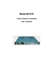
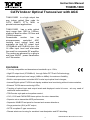
Instruction Manual
TIN40R-1000
CATV Indoor Optical Transceiver with AGC
TIN40-1000R is a high output two
way indoor optical fiber node for
CATV, SMATV, FTTx, MDU or
private business applications.
TIN40-1000R has a wide optical
input range from 1200 to 1600nm,
making it ideal for either 1310nm and
1550nm systems.
Downstream
section
has
an
microprocessor
controlled
AGC
tracking input optical level and
maintains an high RF output level
(37/50dBmV with 13dB tilt) over -8 to
+4 dBm input level and eliminates
the need for a separate RF amplifier.
The nodes are powered by a plug-in
wall type 24VDC power transformer
via F-connector.
FEATURES
• Two way compatible and downstream bandwidth up to 1GHz,
• High RF output level (37/50dBmV) through GaAs-FET Push Pull technology,
• Extended optical input level range (-8dBm to 4dBm) for maximum flexibility,
• Built-in microprocessor controlled AGC tracks input optical level changes,
• Internal Digital optical TX/RX level display enables level monitoring without instrumentation,
• External TX/RX status monitoring LEDs,
• Tracking of optical input and output levels and displayed under lid cover, w/o any need of
additional instrumentation,
• TBLE series style pad and equalizer control,
• 1310, 1550 and CWDM DFB laser options for return transmitter,
• Superior return transmitter NPR performance,
• Separate -20dB RF test ports for forward and reverse directions,
• Surge protection (6kV) at RF output,
• SCTE compliant F type connectors,
• Diecast aluminum housing for excellent heat dissipation and RFI shielding.
1
TIN40-1000R User Manual R2 June 14 2014
Instruction Manual
TIN40R-1000
SPECIFICATIONS (Typical)
Typical, for T = 20ºC
Parameter
Notes
Forward
Optical Performance
Wavelength
1200 - 1600
Max.Range
Input Optical Power
-8 to +4 (see Fig 2)
Digital Display
Test Point
-8 ... +4
Green LED
Optical Indicator
> -8
RF Performance
Plug-in Diplex Filters
Bandwidth
54 - 1000 / 85 - 1000
Gain Tilt
0…3
Stability
±1
Return Loss
-16
Test Point
-20
Link Performance (-1 dBm optical input power, NTSC77 channel, OMI=%3,5)
Output Level (Tilted)
35/48
37/50
AGC Setting
A8
A10
CNR
-51
-51
CSO
-64
-63
CTB
-64
-60
Units
nm
dBm
dBm
dBm
MHz
dB
dB
dB
dB
dBmV
dBc
dBc
dBc
Return
Optical Performance
Wavelength
DFB, 1310
Output Power
2mW
Test Point
Digital Display
-8 ... +4
Optical Indicator
Green LED
> 0,25
RF Performance
Bandwidth
5 - 42 / 5 - 65
Plug-in Diplex Filters
Flatness
±1
Input Level Control
Plug-in attenuator (TBLE)
Return Loss
? -16
Test Point
-20
Link Performance (6dB link loss, 10 km fiber + optical attenuator)
Optimum Total Input Level Range
18
NPR Peak / Input Level
pls. refer to NPR
53 / 21
TX Input Level (@ NPR=-41dB)
chart
8 - 21
TX Input Level (@ NPR=-38dB)
5 - 21
Electrical & Physical Performance
Impedance
75
Surge Withstand
In / Out
IEEEC62.41 Cat.A3(6kV,200A)
Powering
with wall type external power supply (11-36Vdc)
Power Consumption
8
Temperature
-30 to +55
Enclosure
Aluminum diecast housing (IP54)
Weight
1,7 /3.7
Dimensions
19,5 x 13,6 x 7,5 / 7-5/8 x 5-3/8 x 3
2
nm
mW
dBm
mW
MHz
dB
dB
dB
dBmV tot
dB / dBmV tot
dBmV tot
dBmV tot
ohm
Watt
°C
kg / lb
cm / inch
TIN40-1000R User Manual R2 June 14 2014
Instruction Manual
TIN40R-1000
Block Diagram
NOTE TO CATV SYSTEM INSTALLER
This reminder is provided to call the CATV System Installer’s attention to Article 820-40 of the NEC that
provides guidelines for proper grounding and, in particular, specifies that the cable ground shall be connected to
the grounding system of the building, as close to the point of cable entry as practical.
INSTALLATION AND GENERAL SETUP GUIDELINES
1. Mount the TIN40-1000R to mounting panel to maintain a stable physical
condition and operation.
2. Test the optical input power on the system downstream cable with an
optical power meter to verify that it is within the optical input range
specification.
3. Clean the optical connectors on the node and on the service cable then
connect them together, matching the system downstream cable to the
node receiver and the system upstream cable to the laser transmitter.
4. Verify that the total upstream RF signal level is within the node’s specified
input range, then connect the coaxial cable to the node’s RF In/Out F-port.
Connect the system ground to the ground screw located directly below the
output optical connector.
5. Route all the cables (RF, fiber, power, ground) neatly around the node to
make a tidy and safe installation.
6. Apply power to the node and verify that the node’s Optical LEDs
illuminate.
INSTALLATION PRECAUTIONS TABLE
PRECAUTIONS
REQUIREMENT
Facilitate service and maintenance
Allow a minimum of 35 in. (90 cm) clearance in front of the equipment rack(s).
Avoid direct heating or air conditioning
If unavoidable, use deflector plates.
AC Power source outlets
Locate equipment near sufficient outlets to provide power for test equipment and power tools.
Rack support
Make certain rack supports are sufficiently rigid to support rack(s).
Building leakage
Beware of dripping water onto equipment from leaky roofs, waveguide roof entries, and cold
water pipe condensations.
3
TIN40-1000R User Manual R2 June 14 2014
Instruction Manual
TIN40R-1000
FORWARD PATH SET-UP
For optical levels monitoring and for forward path output level set-up refer to the “Controls and AGC
Operation” section at page 5 of this manual.
1. Set the display to monitor optical input power (“O” parameter on the display). Verify that it is
within your expectation and that it is within the node’s specified input range.
2. Plug an equalizer into the forward path mid stage socket. A 12dB equalizer will set the output to
the specified slope, or use a value according to your system design.
While monitoring the forward output test point (-20dB) use the push button controls to set the output
level in either fixed or AGC mode (“F” or “A” parameter on the display) for the proper output level.
Verify that the level is correct at both ends of the bandwidth.
REVERSE PATH SET-UP
1. Set the display to ” L” parameter to monitor laser output power. Check that the optical level is
within node’s specified value, and that it is sufficient to operate over your link loss.
2. Fig.1. shows a typical NPR vs. Total RF input power curve of DFB lasers.
For an optimum operation total RF input level that is 2 to 4dB to the left of the peak on the NPR
vs. Input Level curve (Fig 1 below) should be applied. This will preserve the total level from any
clipping and keep it above thermal noise.
The following equation can be used for the calculation of total input power level:
Operating Point (dBmV) = 10Log(10(S1/10) + 10(S2/10) + …. + 10(Sn/10) ); S1, Sn are the dBmV levels
of each upstream service
While calculating total power level, please consider 20dB loss of the TP (test point) and reverse
path (upstream) JXP pads attenuation value (which is 0 dB as factory default)
4
TIN40-1000R User Manual R2 June 14 2014
Instruction Manual
TIN40R-1000
CONTROLS AND AGC OPERATION
There are three push buttons that control the LED display to monitör the optical levels and to set the
output level including AGC function. The middle button is the "ENTER" button.
The display reads the following;
• Optical Input Power “O” – Monitoring Only
The display will show optical input power in terms of dBm.
* Please see the below table (Table 1) for dBm to mW conversion.
• Upstream Laser Output Power “L” - Monitoring Only
The display will show laser output power in terms of dBm.
* Please see the below table (Table 1) for dBm to mW conversion.
• Fixed Forward Output Level Setting “F”
User can use fix required RF output level.
*AGC is disabled at this at the setting.
• AGC Forward Output Level Setting “A”:
Enables AGC mode and stabilizes the fwd RF output level.
* Dot indication on the left shows that AGC is active
Pressing "Enter" cycles through two menus;
• First pressing enables to access optical monitoring menu; "F" and "A".
• Second pressing enables to access output level adjustment menu; "L" and "O".
Pressing Left and Right cycles through two menus;
• On the output level adjustment menu; pressing left and right cyles between "F" and "A".
• On the optical monitoring menu; pressing left and right cyles between "L" and "O".
dBm --> mW
mW --> dBm
dBm --> mW
mW --> dBm
dBm
mW
mW
dBm
dBm
mW
mW
dBm
10
10
5
6,98
-1
0,79
2,25
3,52
9
7,94
4,75
6,76
-2
0,63
2
3,01
8
6,3
4,5
6,53
-3
0,5
1,75
2,43
7
5,01
4,25
6,28
-4
0,39
1,5
1,76
6
3,98
4
6,02
-5
0,31
1,25
0,96
5
3,16
3,75
5,74
-6
0,25
1
0
4
2,51
3,5
5,44
-7
0,19
0,75
-1,24
3
1,99
3,25
5,11
-8
0,15
0,5
-3,01
2
1,58
3
4,77
-9
0,12
0,25
-6,02
1
1,25
2,75
4,39
-10
0,1
0,2
-6,98
0
1
2,5
3,97
-11
0,07
0,15
-8,23
TIN40-1000R User Manual
Table 1 – dBm to mW conversion table
5
R2 June 14 2014
Instruction Manual
TIN40R-1000
Forward Output Level Adjustment
Disable AGC and Adjust RF Output Level by Fix Mode – Mode "F"
To Access this menu, use the following steps;
Enter > Right Button > Enter
The AGC will be disabled. User can use + - buttons (left and right) to change the numeric
value blinking on the display, which results in a change in RF output level in terms of 1 dB.
In this mode, RF output level changes directly with optical input power.
After setting the RF output level, press E button to apply and save the setting.
AGC Forward Output Mode “A”
To Access this menu, use the following steps;
Enter > Right Button x2 > Enter
AGC mode enables the AGC circuit and stabilizes the fwd RF output level over variations in input
optical power. A dot is displayed to indicate that AGC is active. User can use + - buttons (left and
right) to change the numeric value blinking on the display The allowed variation in input optical
power is dependent on the user AGC setting (refer to Fig 2 on page 6).
Valid setting range is dynamically calculated according to optical input power. Therefore, user can
choose an A setting In this mode, the device will preserve the RF output level independently from
the changes in optical input power levels.
After setting the RF output level, press E button to apply and save the setting.
Example: A typical set up for 32/45 dBmV output level (with –1dBm optical at 3.5% OMI) will use a
12 dB equalizer and a A05 (with AGC ON) or F06 (with AGC OFF) setting. At A05 AGC setting, as it
can be observed from Fig 1, this will compensate an optical input range from –6 to +4.0dBm. This
will lead to RF head room of 11 dB (16-5 = 11dB; ‘16’ value is maximum A setting) and whereas this
head room is 21 dB for below (5-(-16) = 21dB; -16 value is minimum A setting). If the optical power
decreases to –6 dBm from -1dBm (5 dB reduction) then the RF output will also decrease by 10 dB
(2x5=10 dB). Therefore, 11 dB head room is sufficient to be able to compensate 10 dB optical input
variation. If the optical power increases to +4dBm (i.e. with 5dB increase) then the RF output will
also increase by 10 dB (2x5 = 10dB), which stays in the 21 dB head room.
Fig. 2 - AGC Setting and Input Optical Power
"A" setting
16
14
"A" Setting (1dB steps)
12
10
8
6
4
2
Optical Input Power (dBm)
-8
-7.5
-7
-6.5
-6
-5.5
-5
-4.5
-4
-3.5
-3
-2.5
-2
-1.5
-1
-0.5
0.5
1
1.5
2
2.5
3
3.5
4
-2
-4
-6
-8
-10
-12
-14
-16
-8 -7,5 -7 -6,5 -6
-5,5
-5 -4,5 -4
-3,5
-3 -2,5
-2 -1,5
-1 -0,5
Optical Input Power (dBm)
0
0,5
1
1,5
2
2,5
3
3,5
4
6
TIN40-1000R User Manual R2 June 14 2014