1
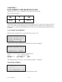
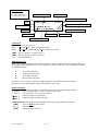
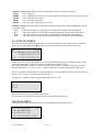
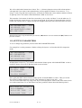
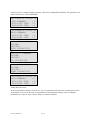
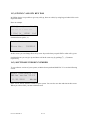
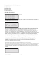
AYBEY ELEKTRONIK SWLINE Lift Control System USER MANUAL F/7.5.5.02.04 R:3 1 /31 SWLINE LIFT CONTROL SYSTEM USER MANUAL VERSION: 1.04 AYBEY ELEKTRONIK LTD. STI. Kartal Cad. No:39 81450 Yakacik Istanbul / Türkiye Tel: (90) (216) 377 08 02-309 06 45-309 06 54-309 07 18 Fax: (90) (216) 451 58 68 e-mail: [email protected] Web: www.aybey.com F/7.5.5.02.04 R:4 2 / 31 CONTENTS CONTENTS……………………………………………………………………………….. PREFACE…………………………………………………………………………………. SWLINE SERIES BOARDS AND FUNCTIONS………………………………………... PANEL VOLTAGE INFORMATION……………………………………………………. OUTPUT TERMINALS AND THE MEANINGS OF THE ABBREVATIONS………… CHAPTER 1: LCD SCREEN AND KEYPAD USAGE………………………………….. 1-A) STARTUP SCREENS…………………………………………………………………………….. 1-B) MAIN SCREEN…………………………………………………………………………………... 1-C) INPUT SCREENS………………………………………………………………………………… 1-D) MAIN MENU……………………………………………………………………………………... 1-E) SETTING PARAMETERS……………………………………………………………………….. 1-F) GIVING CALL BY KEYPAD……………………………………………………………………. 1-G) SOFTWARE VERSION NUMBER……………………………………………………………… CHAPTER 2: PARAMETERS……………………………………………………………. 2-A) P1-MAIN PARAMETERS……………………………………………………………………….. 2-B) P2-AUXILIARY PARAMETERS………………………………………………………………... 2-C) P3-TIMINGS……………………………………………………………………………………… 2-D) P4-FLOOR PARAMETERS……………………………………………………………………… 2-D-1) K1-SET DISPLAYS……………………………………………………………………………… 2-D-2) K2-K3-SET DOORS…………………………………………………………………………….. 2-D-3) K4-CABIN CALLS……………………………………………………………………………… 2-D-4) K5-HALL CALLS………………………………………………………………………………... 2-D-5) K6-ENCODER PULSE OF FLOORS...………………………………………………………... 2-D-6)K7 GENERAL PULSE................................................................................................................... 2-D-7)K8 CALL REGISTER PERIODS.................................................................................................. 2-E) P5-MAINTENANCE TIME………………………………………………………………………. 2-F) P6-OUTPUT DEFINITION……………………………………………………………………….. 2-G) P7-INPUT DEFINITION…………………………………………………………………………. 2-H) P8-DATE&TIME.………………………………………………………………………………… 2-I) P9-UTILITIES…..………………………………………………………………………………… 2-I-1) R1-DISPLAY UTILITY……………………..…………………………………………………… 2-I-2) R2-FACTORY SETTINGS……………………………………………………………………….. 2-I-3) R3-SET PASSWORD…………..………….……………………………………………………… 2-I-4) R4-MODEM SETTINS..….……………………………………………………………………... 2-I-5) R5-RESET PULSES…………..………….……………………………………………………… 2-I-6) R6-OTHER UTILITIES……..………….……………………………………………………… CHAPTER 3: ERROR LOG…………………………..…………..……………………… CHAPTER 4: VARIABLES AND LANGUAGE……..…………..……………………… F/7.5.5.02.04 R:4 3 / 31 PAGE 3 4 5 6 7 8 8 8 10 10 11 14 14 15 15 17 19 20 21 22 22 23 23 24 24 25 25 26 27 28 28 28 28 29 29 29 30 31 PREFACE Swline Series Lift Control System has been designed to fulfill the needs of lift sector at new age. One of the main aims of this series is to integrate lift control system with today’s advanced computer systems. Swline Series Lift Control System is controlled by a 16-bit high performance microcontroller. Beside having all features of general lift control systems, SWline can also communicate with a computer directly or on a modem through telephone line. By this way it is possible to access and observe all lift motion and to edit parameters for authorized users by using a computer. In this manual you find information about using SWline Series Lift Control System and technical documents and schematics. If you think that this manual is not enough or it is not compatible with hardware or software version of your system, you can download latest version of the manual from Aybey Elektronik’s web site (www.aybey.com) or send an e-mail to request by mail. We will continue to develop this product with your support and suggestions. Therefore if you face any problem while using this product or if you have any suggestions to make it better, please inform us by e-mail ([email protected]). Aybey Elektronik F/7.5.5.02.04 R:4 4 / 31 SWLINE SERIES BOARDS AND FUNCTIONS SWM Main Board SWM is the main board of the system. It reads all inputs by itself and via SWPI. It then outputs necessary data to activate motor, doors and signal lamps. The lift parameters are also stored in SWM. They can be easily changed by using keypad and LCD. The LCD on SWM displays the current floor, target floor, state and position of car, all registers, security circuit inputs, state of door(s) and current time on main window. Other inputs can be seen by pressing left button. When an error occurs, error code blinks on main window. SWR Relay Board According to the commands by SWM, it produces the outputs, which perform all relevant processes with respect to car motion and door. By means of the leds on the board, it can be observed that what process the lift is performing. Beside necessary relay outputs, it has 2 extra relays for user specified purposes. SWH Relay Board for Hydraulic Systems SWH is the circuit board used in hydraulic systems instead of SWR. It has relay outputs that can drive all common types of hydraulic system. By means of the leds on the board, it can be observed that which valves are active. Beside necessary relay outputs, it has 2 extra relays for user specified purposes. SWF Relay Board for Frequency Regulated Systems SWH is the circuit board specially designed for frequency-regulated systems instead of SWR. It has several outputs that can drive all common types of inverters. By means of the leds on the board, it can be observed that which outputs are active. Beside necessary relay outputs, it has 2 extra relays for user specified purposes. SWPI Input / Output Board (Parallel) It transmits the calls to SWM and activates register lamps. In order to be able to be identified by SWM, it is necessary to connect the jumper whose number is the sequence number of SWPI board according to the SWM. SWPEX Display and Signal Lamps Driver Board (Parallel) It drives the floor displays (2 displays) and signal lamps. It is added the parallel bus after last SWPI board. Common voltage of signal lamps can be selected by a jumper on the board. SWPS Power Supply Board It supplies all necessary voltages for control circuit, signal circuit and security circuit. It also has leakage detection and cut circuit for security circuitry. F/7.5.5.02.04 R:4 5 / 31 PANEL VOLTAGE INFORMATION F/7.5.5.02.04 R:4 Panel Input Voltage 3 Phase 380v-MP Contactor Supply Voltage 220v AC or 48v DC Phase Protect Cut off Voltage +/- 20 % Brake Supply Voltage 180v DC / 48v DC PTC Cut Off Resistance > 500 ohm Security Circuit Voltage Same as Contactor Supply 1000 Signal Ground 100 Signal Voltage (24v DC) 150 Security Ground 110 Security Voltage Supply Display Common Voltage 100 (24v DC) 6 / 31 OUTPUT TERMINALS AND THE MEANINGS OF THE ABBREVATIONS 1 Phase for Cabin (220v AC) I1, I2, 13, I4 Free Inputs 100 Signal Circuit Supply (+24v DC) IC Common for Free Inputs 1000 Signal Circuit Ground K20 Open Door Signal 110 Security Circuit Supply KA Open Door Signal Output (Transistor 011) 12 Busy Signal KK Close Door Signal Output (Transistor 011) 120 Stop Circuit Return M0…M4 Magnetic Switches for Grey Code 10-12AC 12v AC MK Stop Switch (Magnet) 130 Door Contacts Return MK1, MK2 Stop Switch for Hydraulic System (up and down) 140 Door Locks Return MP Neutral (Main power) 150 Security Circuit Common R, S, T Phases 18AC 18v AC RD Down Direction Contactor 190 Hall call common for Simple Push Button RF Low Speed Contactor 1A, 1B,..,1G Right Display Outputs RH High Speed Contactor 2 Cabin lamp RU Up Direction Contactor 2000 Negative terminal of Brake S1, S2 Programmable Relay Outputs 2001 Positive terminal of Cam SFP Brake and Cam Fuse SK Contactor Fuse (220v AC) 2A, 2B,.., 2G Left Display Outputs 31 Down Arrow Signal SKL Cabin Lamp Fuse 32 Up Arrow Signal SWCX Security and Contactor Supply Fuse 35 Over Load Signal SWF SW Series Relay Board for Variable Speed Systems 39 Out Of Service Signal (Inspection) SWH SW Series Relay Board for Hydraulic Systems 500 Inspection Up Button SWM SW Series main board 501 Inspection Down Button SWPEX SW Series Display and Lamp Driver Board 55AC 55v AC SWPI SW Series I/O board 802 Minimum Load Contact SWPS SW Series Power Supply Board 804 Over Load Contact SWR SW Series Relay Board 805 Full Load Contact SXX Fuses 810 Negative terminal of Cam T1-T2 PTC Motor thermistor terminals 810A Open Door Signal (automatic door) TMS Thermal Magnetic Circuit Breaker 817 Lower Limit (End of high speed way) TR Thermal Relay 818 Upper Limit (End of high speed way) U1,V1,Y1 Motor High Speed Inputs 827 Lower Last Limit (End of travel way) U2,V2,Y1 Motor Low Speed Inputs 828 Upper Last Limit (End of travel way) VK Contactor Supply Voltage 840 Positive terminal of Brake 869 Inspection control input C0,C1..C16 Registration button inputs/register lamp outputs DTS Close Door Signal FAN Supply Voltage for Motor Fan FIRE Fire Contact FKR Phase failure detector F/7.5.5.02.04 R:4 7 / 31 CHAPTER 1 LCD SCREEN AND KEYPAD USAGE SWline Series has a 4-row * 20-character LCD screen and 6-key keypad. Keys are located as below: ← ↑ → ESC ↓ ENT Functions of the keys differ in different menus. But generally, ESC is used to exit current menu, ENT is used to enter a menu and confirm any input, up and down arrows are used to move in menu lists and change value of a variant, left and right arrows are used to move left and right while changing the value of variant. 1-A) START UP SCREENS When system is energized first or restarted the below screen is seen. AYBEY ELEKTRONiK LTD SWline series Vx.yy System parameters loading ... Ok At this moment system parameters are loaded and below screen is displayed. AYBEY ELEKTRONİK LTD SWline series Vx.yy DD/MM/YYYY HH:MM Meanings of the items in this screen are explained below. Vx.yy “ x.yy” Software Version DD/MM/YYYY Day/Mounth/Year DATE HH:MM Hour : Minute TIME After displaying this screen about 3 second “MAIN SCREEN” is displayed. 1-B) MAIN SCREEN [SDL][→ ←] ........ [ 01=][INS]STOP 16:37 G+1 The main screen shows the most important lift parameters briefly. F/7.5.5.02.04 R:4 8 / 31 Security Circuit S..:Stop(120) D..:Door Contact(130) L..:Door Lock(140) Cabin door is closed. Hour : Minute System is in Duplex mode [SDL][] 13:35 ..-.... .... * ERROR NO:5* [ 01=][t02]FAST G+1 Calls Error code blinks Direction Lift communicating with other lift. Lift is manager of group Current Floor Target Floor Car’s Speed Car is exactly at floor TOP ROW: [S ] : Stop circuit is closed. [SD ] : Stop and Door Contact circuits are closed. [SDL] : Stop, Door Contact and Door Lock circuits are closed. [] : Door is opening. (CAM is active.) [] : Door is closing. (CAM is inactive.) 13:35 : HOUR:MINUTE MID-ROWS (2,3): Row 2 and 3 shows Call Registers. Most left character of Row 2 shows the calls for bottom floor. As moving right, floor number increases. One character is used for each floor. The meanings of symbols are explained below: − : No Call for this floor : Cabin Call for this floor : Up Call for this floor : Down Call for this floor In a floor 1, 2 or 3 of these symbols can appear together at the same character (except ). In these rows only defined floor number of characters can be seen. BOTTOM ROW: Columns[2,3,4,5] : This group shows information about car’s floor and moving direction. [ 05=] : Car is exactly at floor 5. (Car is exactly at floor level) [ 05 ] : Car is at floor 5. (Car is between floors) [ 05 ] : Lift has a target on up direction. [ 05 ] : Lift has a target on down direction. Columns[8,9,10]: This group shows information about car’s target and lift’s run mode. [INS] : Lift is in INSPECTION mode. [t__] : Lift has no target. [t03] : Lift has a target of Floor 3. F/7.5.5.02.04 R:4 9 / 31 Columns 12,13,14,15,16: This group shows information about car’s motion and speed. STOP : Car is stopping. START : Car is stopping but about to move. Lift is preparing conditions for moving.(Closing door) SLOW : Car is moving at slow speed. FAST : Car is moving at fast speed. HIGH : Car is moving at high speed. (over 1m/s) Columns 18,19,20: This group shows information about group operations. If lift is SIMPLEX you can not see this group. G+1 : Lift is the manager of a group and can communicate with the other lift(member). G-1 : Lift is the manager of a group but can not communicate with the other lift(member). G+2 : Lift is the member of a group and can communicate with the other lift(manager). G-2 : Lift is the member of a group but can not communicate with the other lift(manager). 1-C) INPUTS SCREEN You can see the most important inputs and car’s motion information on the main screen as explained above. To see other inputs push (← ←) button on main screen and you will see the below screen. xxx..x..........xxxx 01234MM888855FDK8888 KK600000IT21122 SDL 12954201RS07878 On this screen you can see the current case of some important input signals. In SWline Series no led is located at signal inputs. Instead LCD screen is used to observe input signals. The input signal names on this screen are read from top to bottom. “x” symbol on the top row means that the input below “x” is active. And “.” symbol on the top row means that the input is not active. The first 5 column (01234) of Row 2 means M0, M1, M2, M3, M4 inputs. The first 3 columns (SDL) of Row 4 are the same as on main screen described above. If you push (→) button on that screen the following screen is seen. .... IIII 1234 This screen shows the programmable input signals. If you want to turn one back from any screen you can push ESC button once. 1-D) MAIN MENU If you push ENT button on Main Screen you see the following Main Menu screen. > M1-VARIABLES M00 M2-PARAMETERS M3-ERROR LOG M4-LANGUAGE/LiSAN F/7.5.5.02.04 R:4 10 / 31 We will see this kind of menus lots of times. The ‘>’ (Pointer) character on most left column points a sub menu and if you want to enter pointed menu you must push ENT button. You can move ‘>’ by using (↑) and (↓) up and down respectively. All menus in SWline has a menu number and this is shown at right top corner. The number of the Main Menu is M00 as seen above. This menu has 5 sub-menus. In the first screen above you see only 4 of them. To see the other use (↓) button .By this way cursor moves 1 row down at each push. If you push (↓) button when the cursor at bottom row, all lines moves 1 upper, the top line disappear and a new line comes from down as below: M2-PARAMETERS M00 M3-ERROR LOG M4-LANGUAGE/LiSAN >M5-SERViCES Instead of moving 1 step at each time you can use (→) button to see next 4 items and (← ←) button to see previous 4 items. 1-E) SETTING PARAMETERS To see or change any parameter you must enter M2-PARAMETERS menu. For example let’s set the parameter ‘Number of Stops In System’. At first take the lift in inspection mode. M1-VARIABLES M00 >M2-PARAMETERS M3-ERROR LOG M4-LANGUAGE/LiSAN In Main Menu screen use (↑),(↓) buttons and when the Pointer points ‘M2-PARAMETERS’ as above, push ENT button. You will see the M20 menu screen as below. >P1-MAIN PRMs M20 P2-AUX. PRMs P3-TIMINGS P4-FLR PARAMET. Here again push ENT button when the Pointer points ‘P1-MAIN PRMs’ as above. Then you see the first 4 items of Main parameters as below. This menu has 12 items as A01,A02…..A12. You can see the other items buy using arrow keys as described before. Some of the items in this screen are in abbreviated form. To see full form of any item, push ENT button when the Pointer points it. >A01-NUM.OF STOPS:16 A02-COMMAND :4 A03-LIFT TYPE :2 A04-DOOR TYPE :2 F/7.5.5.02.04 R:4 11 / 31 To change the parameter A01 push ENT again. A01-NUMBER OF STOPS IN SYSTEM ?000016 Now, you see general parameter change screen. In this type of screens you always see 6 digit numbers. When you first enter this screen cursor is always located under left most digit. You can increase or decrease value of the digit under which cursor is located , by using (↑) , (↓) buttons respectively. You can move cursor left and right by using (→), (←) buttons. In this screen stored parameter data is 16 and cursor is located under digit (6). Now let’s see some example about how to change value of a parameter. ?000016 (↓) ?000015 (←) ?000015 (↑) ?000025 (→) ?000025 (↓) ?000024 After setting the parameter if you push ENT the new value on screen is saved. But if you push ESC changes are cancelled. In both cases you turn previous screen and you see value of parameter. Here we push ENT and see the following screen. >A01-NUM.OF STOPS:24 A02-COMMAND :4 A03-LIFT TYPE :2 A04-DOOR TYPE :2 So we have changed number of floor in system as 24 and this change is saved and stored in memory F/7.5.5.02.04 R:4 12 / 31 On this screen let’s change another parameter ‘A02-LIFT COMMAND SYSTEM’. This parameter is in abbreviated form as ‘A02-COMMAND’. >A01-NUM.OF STOPS:24 A02-COMMAND :4 A03-LIFT TYPE :2 A04-DOOR TYPE :2 (↓) A01-NUM.OF STOPS:24 >A02-COMMAND :4 A03-LIFT TYPE :2 A04-DOOR TYPE :2 (ENT) A02-LIFT COMMAND SYSTEM ?000004 FULL COLLECTIVE (↓) A02-LIFT COMMAND SYSTEM ?000003 UP COLLECTIVE (↓) A02-LIFT COMMAND SYSTEM ?000002 DOWN COLLECTIVE (ENT) A01-NUM.OF STOPS:24 >A02-COMMAND :2 A03-LIFT TYPE :2 A04-DOOR TYPE :2 Setting has been saved. In the A02 parameter change screens above, you see explanations at bottom row according to the value of parameter. You will see this type of explanations in some parameter change screens if changed parameter has a value of a type, system, shape etc. instead of number. F/7.5.5.02.04 R:4 13 / 31 1-F) GIVING CALLS BY KEY PAD In SWline Series it is possible to give any call (up, down or cabin) by using keypad when lift is not in inspection mode. Here an example. [SDL][→ ←] 16:37 ........ ........ [ 01=][t__]STOP G+1 On Main Screen push (→) . Cabin Button Floor No.. ?000002 In this screen you can change floor no by arrow keys and when you push ENT a cabin call is given. On Main Screen you can give up and down call in the same way by pushing (↑) , (↓) buttons respectively. 1-G) SOFTWARE VERSION NUMBER To see software version of your system, on Main Screen push and hold ESC. You see the following screen. AYBEY ELEKTRONİK LTD SWline series V2.63 11/03/2005 HH:MM Here ‘V2.63’ shows software version of your system. You can also see date and time in this screen. When you release ESC you turn to Main Screen. F/7.5.5.02.04 R:4 14 / 31 CHAPTER 2 PARAMETERS All information about lift and control system settings and timings are stored in system parameters. These parameters are classified into several groups to make it easy for users. These groups are: • MAIN PRMs : These are the most important and necessary parameters for lift to function properly. (Axx) • AUX. PRMs : This group includes secondary parameters for lift and the parameters about control system (SWline Series) working conditions.(Bxx) • TIMINGS : These are timing parameters for lift.(Cxx) • FLR PARAMET. : These are the parameters that can have different value for each floor. • MAINTENANCE: This is the date at which system requires maintenance. • OUTPUT DEF. : This parameters control user-defined relay outputs. • INPUT DEF. :This parameters control user-defined inputs. • DATE/TIME : Setting Real Time Clock and date. 2-A) P1-MAIN PARAMETERS: [A01] NUMBER OF STOPS 2-32 This parameter stores the number of stops in lift system. Be sure to have necessary I/O boards (SWPI) connected to the system required for the selected command system in [A02]. [A02] COMMAND SYSTEM 0 Simple Push Button Car and hall call buttons are tied together. There is no call memory 1 Simple Collective Car and hall call buttons are tied together. Call memory is present. 2 One Button Down Collective Car and hall call buttons are connected separately. Car calls are collective in both directions where hall calls are collective when the lift moves downwards. This configuration is useful in residential buildings where the main entrance is in the base floor 3 One Button Up Collective Car and hall call buttons are connected separately. Car calls are collective in both directions where hall calls are collective when the lift moves upwards 4 Two Buttons Full Collective Car, hall up and hall down buttons all are connected separately. Car and landing call are all serviced in full collective manner. [A03] LIFT TYPE 1 One speed rope lift 2 Two speed rope lift 3 Hydraulic lift 4 VVVF1 5 VVVF2 6 FUJI closed loop 7 RST 8 VVVF3 F/7.5.5.02.04 R:4 15 / 31 [A04] DOOR TYPE 0 Semi-automatic wing landing door, no cabin door 1 Semi-automatic wing landing door, with automatic cabin door 2 Full automatic cabin and landing door [A05] FLOOR SELECTOR SYSTEM 0 Gray code based bi-stable magnetic switches 1 Counter 2 Incremental Encoder 3 Absolute Encoder [A06] PRE-OPENING DOORS 0 No 1 Yes [A07] HYDRAULIC LEVELING SYSTEM 0 No Releveling 1 Releveling system will be used in hydraulic lift (Motor is running) 2 Releveling system will be used in hydraulic lift (Motor is not running) [A08] NUMBER OF AUTOMATIC DOORS IN CABIN 1 There is only one cabin door 2 There are two doors in cabin. Do your selections of driven doors for each floor in M2 SET PARAMETERS → P4-FLR PARAMET. → K2 and K3 [A09] CONTROLLER-SHAFT COMMUNICATION 0 Parallel Communication between controller and car and landing panels. One to one cable is connected between controller terminals and signals or buttons. Call registers are controlled by SWPIs. 1 Serial RS-485 communication between controller and car and landing panels. No SWPIs are used for call registers and buttons. [A10] NUMBER OF STOPPERS 0 There is only one floor level stopper (MK). 1 There are two floor level stoppers (MK1 and MK2). When this option is selected then M4 terminal serves as MK2. If lift type is selected as hydraulic (A03=3) where the driven force in up and down directions is different then the system automatically uses M4 as MK2. This option may be also used in other lift types besides hydraulic. [A11] USE OF 3rd SPEED 0 3rd speed is not used. 1 This option is used in variable speed lifts where the car speed exceeds 1m/s. In this case the lift will have slow, fast and high speeds. [A12] LIFT GROUP NUMBER 0 Simplex, the lift works alone. 1 Duplex, the lift works in a group of lifts. The lift with the group number 1 administrates the landing calls. 2 Duplex, the lift works in a group of lifts. The lift with the group number 2 gets landing calls from lift with the group number 1. F/7.5.5.02.04 R:4 16 / 31 [A13] MISSING FLOOR (DUPLEX LIFT) 0 No level difference of both group lifts 1 The base floor of group 2 is one floor above group 1 2-B) P2-AUXILIARY PARAMETERS [B01] AFTER DOOR LOCK FAILURE 0 The system continues operation 1 The system is blocked if the number of consequent errors have been repeated as the number stored in the parameter B12 2 All call registers are cleared. [B02] ERRORS ARE REPORTED ON THE SCREEN 0 When an error occurs the current screen is not left. Only when the screen is the main screen then a flashing message about the error is displayed. 1 When an error occurs the current screen is left and an error screen is displayed where all the information about the error is given. After a few seconds of display time previous screen is restored. [B03] PARK FLOOR DEFINITION 0 No park floor is defined. 1 System has a park floor. When the lift is in park at this floor then it will wait there with closed doors. 2 System has a park floor. When the lift is in park at this floor then it will wait there with open doors [B04] PARK FLOOR 0-31 Park floor number. When [B03] is 1 or 2 and the lift has no calls about 2 minutes then moves to this floor and stays there until a call comes with the door specified in [B03]. [B05] FIRE FLOOR 0-31 Fire floor number. When the fire input of the lift is activated then the car immediately moves to this floor. [B06] MAXIMUM CABIN CALLS 1-32 Maximum number of allowable cabin calls. [B07] BREAKPOINT 0 Only for service of the operating system. Leave it as 0. Do not change it. [B08] CONTINUE IN SIMPLE ERRORS 0 The system is stopped after all errors. 1 The system continues its operation after some simple errors which are not in security loop or related with car motion. [B09] WAIT WITH OPEN DOOR IN FLOOR 0 The car waits with closed doors in floor. 1 The car waits with open doors in floor. F/7.5.5.02.04 R:4 17 / 31 [B10] ERROR MODEM REPORT 0 Not Activated 1 SwOnline: In case of error system calls to remote computer via modem. 2 GSM SMS : In case of error system send a short message to defined cellular phone. 3 GSM CALL: In case of error system calls to defined cellular phone. [B11] SCHEDULED STATE->MODEM 0 Not Activated 1 Activated [B12] MAXIMUM ERROR REPEAT 1-100 Maximum allowed number of the same error repeat. System locks itself when exceeded. [B13] LANGUAGE 0 LCD screen language is Turkish. 1 LCD screen language is English. [B14] DISPLAY DRIVER BOARD 0 SWPEX / 7 SEGMENT DRIVER 1 SWPEX-2 / 7 SEGMENT DRIVER 4 SWPEX-2/16 SEGMENT DISPLAY DRIVER [B15] PROGRAMMABLE RELAY BOARD 0 Not used 1 Floor indicator lamps 2 Gray code output of floor position 3 Binary output of floor position [B16] PAWL CONTROL 0 Active 1 Not active [B17] HALL CALLS INHIBIT 0 Hall calls are allowed 1 Hall calls are inhibited. [B18] CONT INPUT 0 Not active 1 Active [B19] DOOR SELECTION 0 Normal. The parameters given in Floor Parameters section are valid for door selection at each floor. 1 The door to be opened at each floor is determined by the programmable inputs. F/7.5.5.02.04 R:4 18 / 31 [B20] AFTER A STOP FAILURE 0 System continues to work 1 System is blocked [B21] AFTER A MAXIMUM TRAVEL TIME FAILURE 0 System continues to work 1 System is blocked 2-C) P3-TIMINGS [C01] BUSY PERIOD 0-999 Busy period. Each number is 0.1sec. [C02] PARK WAIT TIME 0-10000 This parameter stores the time period for the car to move to the park floor. Each number is 0.1sec. [C03] OPEN WAIT PERIOD 0-300 This parameter stores the time period for the automatic door to wait open before closing. Each number is 0.1sec. [C04] DOOR OPEN PERIOD 0-999 This parameter stores the time period necessary for the automatic door to open. Each number is 0.1sec. [C05] DOOR LOCK WAIT PERIOD 0-999 This parameter stores the time period necessary for the automatic door to close. This parameter is controlled by checking lock (terminal 140) after door close command. Each number is 0.1sec. [C06] IN FLOOR WAIT PERIOD 0-999 This parameter stores the time period for the car to wait before departing for the next call in collective systems. Each number is 0.1sec. [C07] STARTUP DELAY 0-100 This parameter stores the time delay for the car to wait before departure after lock contact is closed. Each number is 0.1sec. [C08] FLOOR PASS TIME 0-9999 This parameter stores the maximum time allowed to pass without changing the current floor number when the car is in fast or high speed (in 3 speed systems). Each number is 0.1sec. [C09] SLOW SPEED MAXIMUM TRAVEL TIME 0-9999 This parameter stores the maximum travel time allowed to pass when the car is in slow speed. Each number is 0.1sec. [C10] SERIAL COMMUNICATION ERROR PERIOD 0-500 This parameter stores the maximum time allowed to pass without getting a successful answer in serial communication mode where A09 is 1 . Each number is 0.1sec. F/7.5.5.02.04 R:4 19 / 31 [C11] GROUP DOOR OPEN WAIT PERIOD 0-999 When the lifts work in group then this parameter specifies the maximum time period in which a lift can hold a hall call as its target as its doors are forced to stay open. After timeout of this period the hall call is left free where any other member of the group can take it as a target. Each number is 0.1sec. [C12] BRAKE DELAY TIME 0-100 Brake delay in ACVV and VVVF systems. Each number is 0.1sec. This parameter defines the time delay for programmable relays for selection number 18. [C13] MOTOR VALVE DELAY TIME 0-999 This parameter determines the delay time between the motor starts to run and the valves are activated in hydraulic lifts in startup. Each number is 0.1sec. [C14] STAR DELTA SWITCHING PERIOD 0-999 This parameter determines the switching time of the motor from star connection to delta connection in hydraulic lifts in startup. Each number is 0.1sec. [C15] VALVE MOTOR DELAY TIME 0-999 This parameter determines the delay time of the valves to shut down after the motor is stopped in hydraulic lifts. Each number is 0.1sec. [C16] MAXIMUM BUSY TIME 0 Inactive 1-30000 If the doors are left open or cannot close for a time period of C16 then the busy signal and cabin light are off until a new call is received. [C20] DTS BUTTON DELAY 0 Inactive 0-100 DTS (Door close button) is inhibited during the time period given in this parameter. The period starts when the car reaches the floor. [C21] MAXIMUM MOTION WAIT PERIOD 0-100 If there is no signal input to the programmable input with code 10 within the time period specified in this parameter after a motion command is received then the system is stopped. [C22] RETIRING CAM DELAY 0-100 Time period to delay the activation of retiring cam after the landing door has been closed for semi-automatic systems. 2-D) P4-FLOOR PARAMETERS In this section you can program the parameters of the system that can vary floor to floor. We call these parameters as Floor Parameter. In screen M20 item P4 is the selection for floor parameters. If you select P4 and press (ENT) key then the following screen is displayed. K1-SET DISPLAYS M24 > K2-SET DOOR A K3-SET DOOR B K4-CABIN CALLS F/7.5.5.02.04 R:4 20 / 31 The menu M24 consists of the following sections: K1-SET DISPLAYS K2-SET DOOR A K3-SET DOOR B K4-CABIN CALLS K5-HALL CALLS K6-ENCODER PULSE 2-D-1) K1-SET DISPLAYS In this section you are faced with the following screen: 00.FLR 01.FLR 02.FLR >03.FLR DISPLAY: DISPLAY: DISPLAY: DISPLAY: -1 0 1 2 When you select any floor by pressing (ENT) key then you can enter the digital display data by using the following display input screen: 03.FLR DISPLAY: LEFT: _ RIGHT: 2 (↑↓ SCAN CHARACTERS) This screen is designed to take input left and right digital characters. When you enter this screen first the cursor is waiting just after ‘LEFT:’. Here either you can skip this field by pressing (ENT) key and accepting the character shown there or select the character by using (↑) or (↓) keys. As you scan characters all ASCII characters will be displayed one by one. You can select any one you want to be displayed in car and landing panels. However the hardware you are using to drive and display these characters limits the characters you actually see on the displays. For example if you have seven segment digital displays on your panels then you can see the characters only if you select in this section the characters of all digits from 0 to 9 and other characters like -, A, b, C, d, E, L, F, H, I, L, P, r, U. If you have such hardware in your system then you cannot see any characters like M or X on panels if you select them. But if you have dot matrix displays and its driving hardware is connected in your system then you can actually display on panels all characters you select in this section. After you have chosen the character you want on the left display press (ENT) key to go to the input field of the right display. You can select the right side display by using (↑) or (↓) keys as in the previous field. After you have chosen the character you want on the right display press (ENT) key to return back to the previous menu. By using the same procedure you can specify all characters for your lift system. This section is for changing display data for any floor. But if you want to reorganize your displays in an ordered manner then you can use special utilities. You can go to this section by following from M20 menu P9-UTILITIES→ R1-DISPLAY UTIL. In this utilities section the following screen is waiting for an input: BASE FLOOR N?000000 F/7.5.5.02.04 R:4 21 / 31 You can change the data by using (↑) and (↓) keys between 0 and maximum floor no. If you specify which floor is the entrance floor to the building then this utility sets the digital display of the entrance floor (base floor) as 0. All floors above this floor are numbered starting 1 and incremented by 1 at every floor. All floors below 0 (base floor) are numbered starting -1 and decremented by 1 at every floor. If you have a regular display order in your system but with a few exceptions then first use the utility explained above and then changes the data for exceptional floors one by one. 2-D-2) K2-SET DOOR A and K3-SET DOOR B This section is designed for selection of active automatic door(s) at each floor. If the system has only one door then do not use this section. In order to use the data given in this section [A08] number of automatic doors in cabin must be 2. 00.FLR >01.FLR 02.FLR 03.FLR DOOR DOOR DOOR DOOR A:1 A:1 A:1 A:1 YES YES YES YES If the system has two doors then they are named as A and B. When you see ‘1 YES’ as data then it means that this door will open at this floor. When you see ‘0 NO’ as data then it means that this door will not open at this floor. If your system has two doors in cabin then you can select freely which doors are active in each floor. In order to change the condition of the door for a specific floor, press (ENT) key in the line of this floor. In the following screen you can change the data by using (↑) and (↓) keys between 0 (NO) and 1 (YES). 03.FLOOR DOOR A WILL IT OPEN ?000001 YES In this screen the data for third floor is displayed as Yes. It means that door A will open at third floor. Here 0 is for NO and 1 is for YES. For door B the same procedure applies for item K3. 2-D-3) K4-CABIN CALLS You can set allowance for cabin calls for any floor by using this section. If you switch off cabin call of any floor then any call coming from car operating panel will be discarded. When you enter this section by pressing (ENT) key in menu M24 then you see the following screen. 00.CABIN 01.CABIN 02.CABIN >03.CABIN CALL: CALL: CALL: CALL: 1 1 1 1 ON PE1 ON OFF In order to select a floor to change its data press (ENT) key in its line. Then you see the following editing screen. You can change the data by using (↑) and (↓) keys between 0 and 1. F/7.5.5.02.04 R:4 22 / 31 03.CABIN CALL ?000001 ON The parameters used in this screen are as follows 0 OFF. A cabin call for this floor is not allowed 1 ON. A cabin call for this floor is always allowed. 2 PE1. If the clock time is within the time interval PERIOD1 which is specified in section K8, then the cabin call is allowed otherwise not allowed. 3 PE2. If the clock time is within the time interval PERIOD2 which is specified in section K8, then the cabin call is allowed otherwise not allowed. 2-D-4) K5-HALL CALLS You can set allowance for hall calls for any floor by using this section. If you switch off hall call of any floor then any call coming from landing operating panel will be discarded. When you enter this section by pressing (ENT) key in menu M24 then you see the following screen. 00.HALL >01.HALL 02.HALL 03.HALL CALL: CALL: CALL: CALL: 1 1 1 1 ON OFF ON PE2 In order to select a floor to change its data press (ENT) key in its line. Then you see the following editing screen. You can change the data by using (↑) and (↓) keys between 0 and 1. 01.HALL CALL ?000001 ON The parameters used in this screen are as follows 0 OFF. A cabin call for this floor is not allowed 1 ON. A cabin call for this floor is always allowed. 2 PE1. If the clock time is within the time interval PERIOD1 which is specified in section K8, then the cabin call is allowed otherwise not allowed. 3 PE2. If the clock time is within the time interval PERIOD2 which is specified in section K8, then the cabin call is allowed otherwise not allowed. 2-D-5) K6-ENCODER PULSE NO OF FLOORS If you select as floor selector in A05 2 (incremental encoder) or 3 (absolute encoder) then you can enter this section and edit the pulse data for any floor. 00.FLR 01.FLR >02.FLR 03.FLR PULSE:xxxxxx PULSE:xxxxxx PULSE:xxxxxx PULSE:xxxxxx F/7.5.5.02.04 R:4 23 / 31 In order to select a floor to change its data press (ENT) key in its line. Then you see the following editing screen. >02.FLR PULSE ?023451 You can change the data by using (↑) and (↓) keys . In order to go from column to column use (←) and (→) keys. D-6) K7- GENERAL PULSE This parameter is used only if [A05] is 2 or 3. The parameters given in this section correspond to the distances that are used for all floors. When you change any pulse number then the distance for the related path is changed in all floors. All of the data given in this section are the distances in encoder pulses to the floor level specified in the previous section. MK1 STOPPER >DOOR ZONE ENCODER FLOOR LEVELLING A) MK1 STOPPER: The distance in pulses between the exact floor level and the point of stop command. B) DOOR ZONE : The section in pulses from the exact floor level to the level in which the automatic door can be opened. The pulse number given in this parameter applies from the floor level up and down. C) ENCODER FLOOR: The distance in pulses where the controller switches to low speed when it reaches its target floor. D) LEVELING: The limits of releveling zone in pulses. The controller activates releveling process between the limits specified by this parameter. E) MK2 STOPPER: The distance in pulses between the exact floor level and the point of stop command when two stoppers are used. D-7) K8- CALL REGISTER PERIODS PERIOD1 08:30-18:30 >PERIOD2 18:30-08:30 You can specify two periods in this section. The first one is used as the time period PE1 and the second is PE2 in sections K5 and K6 where call register allowance is specified. Here the data give is any time of the day is 24 hour time system. As an example for the screen shown above any hall or cabin call register can be active between from 8:30 am to 6:30pm if it is selected as PER1. F/7.5.5.02.04 R:4 24 / 31 2-E) P5-MAINTENANCE TIME You can see or set next maintenance day by using P5 in menu M20. In this section you see current setting of the next maintenance day. NEXT MAINTENANCE 01/07/2006 If you press any key in this screen then you will come to the maintenance date editing screen. NEXT MAINTENANCE DAY..: ?000001 MONTH: ?000007 YEAR.: ?002006 You can enter new maintenance date in this screen. When the date exceeds the maintenance date then the lift cannot be moved. You can also see “MAINT” word in the main screen when maintenance date is exceeded. 2-F) P6-OUTPUT DEFINITIONS It is possible to control some output relays with user-defined events. In order to do this, first select P6 in menu M20. You are faced with the following screen: *OUTPUT DEFINITION* Output No. ?000000 Output Code ?000000 In SWline system there are 2-3 programmable output relays. S1 and S2 can be freely used in all systems where K2 can be programmed only in systems with one automatic cabin door. The summary of these outputs is as follows: OUTPUT NO NAME 1 S1 2 S2 3 K2 CONTACT TYPE NO NO NO – NC REMARKS Always free to program Always free to program If A02 is 1 then free to program. If A02 is 2 K2 serves as the door relay for second door. First you have to enter the output no from the selections in the first table. You have to enter 1,2 or 3 as output channel. Then you can choose which function to connect to this channel from the second table below and complete the output definition. After the procedure described above the defined output relay will be activated according the event you selected. If the state of the lift matches the one you selected the output relay is ON otherwise it is OFF. F/7.5.5.02.04 R:4 25 / 31 Here is the list of events that can be connected to the programmable relays. OUTPUT CODE EVENT WHICH MAKES K2 ON 1 2 3 4 5 6 7 8 9 10 11 12 13 14 15 16 17 18 19 20 21 22 23 24 25 26 27 28 29 30 31 200+i Stop circuit is closed. ( Terminal 120 is on) Stop circuit is open. ( Terminal 120 is off) System is in Inspection mode. (Terminal 869 is on) System is in Normal mode. (Terminal 869 is off) There is an error. There is no error, system works normal. The car is moving in Slow speed. The car is not moving in Slow speed. The car is not moving. The car is moving in any speed. The car is moving in Fast speed. The car is moving in Fast or High speed. Door Lock circuit is closed. ( Terminal 140 is on) Door Lock circuit is open. ( Terminal 140 is off) The cabin is at floor level. The car is staying in Rest and the cabin is at floor level. Direction is up Direction is down Busy The system is moving or in START state BRAKE output for variable speed lifts Upwards relevelling The system is in relevelling motion Waiting for park period The system is in motion or in braking Retiring cam In normal mode : The system is in motion or in braking. In inspection mode : The system is in motion. The car is moving at 3. speed (HIGH). Pawl device output The system is in motion or door lock is on. This output is specially to drive the contactor in speed control systems There is no call registered. The car is staying in rest at ‘i’ th floor. ‘i’ represents the floor at which the car stays and has a range from 0 to maximum number of stops-1. For example 203 represents 4.stop and 200 represents base floor. 2-G) P7-INPUT DEFINITIONS It is possible to define some inputs for a specific job. In order to do this, first select P6 in menu M20. You are faced with the following screen: *INPUT DEFINITION * Input No.. Input Code F/7.5.5.02.04 R:4 ?000000 ?000000 26 / 31 The programmable inputs are denoted by I1, I2, I3 and I4 on the printed circuit boards. INPUT NO 1 INPUT NAME REMARKS A11 must be 0 for programmable input. If A11=1 I1 is I1 2 I2 3 4 I3 I4 INPUT CODE 1 2 3 4 5 6 7 8 9 10 used as high speed (3.speed) down limit switch. A11 must be 0 for programmable input. If A11=1 I2 is used as high speed (3.speed) up limit switch. Free input Free input FUNCTION FIREMAN WATMAN Fast Inspection Travel Photocell Pawl Pressure Pawl active closed Pawl active open Door B open control Door A open control Motor motion detection In order to define an input first you must enter its input code from the first table and desired function from the second table. After this process you can use this input terminal as an input terminal dedicated for the defined function. Be aware of the exception when the lift is used in 3 speed (car speed above 1 m/sec) then I1 and I2 are used automatically as the 3. speed up and down limit switches and the input codes you entered for these are not executed. If input code is 0 then this input is ignored. 2-H) P8-DATE & TIME The time and date of the system can be set in this section. YEAR....:2001 >MONTH...:5 DAY.....:15 HOUR....:16 M26 You can edit any item in this screen after selecting its line by using (↑) and (↓) keys and then pressing (ENT) key. SET DATE AND TIME MONTH... ?000005 You can change the data by using (↑) and (↓) keys . In order to go from column to column use (←) and (→) keys. After you completed your editing press (ENT) key to save the new data. In the same manner you can edit year, month, day, hour and minute. F/7.5.5.02.04 R:4 27 / 31 2-I) P9-UTILITIES This section contains some utilities which are some non-standard procedures which may help you in configurating your system. >R1-DISPLAY UTIL.M28 R2-FACTORY SETT. R3-SET PASSWORD R4-OTH.UTILITIES 2-I-1) R1-DISPLAY UTILITIES In this utilities section the following screen is waiting for an input: BASE FLOOR N?000000 You can change the data by using (↑) and (↓) keys between 0 and maximum floor no. If you specify which floor is the entrance floor to the building then this utility sets the digital display of the entrance floor (base floor) as 0. All floors above this floor are numbered starting 1 and incremented by 1 at every floor. All floors below 0 (base floor) are numbered starting -1 and decremented by 1 at every floor. If you have a regular display order in your system but with a few exceptions then first use the utility explained above and then change the data for exceptional floors one by one. 2-I-2) R2-FACTORY SETTINGS If you want to set all parameters to the values set just after production then you can use this section. 2-I-3) R3-SET PASSWORD You can change your password by this utility. When you enter this menu, current password is asked first. Current Pass?000000 If you enter correct password then you can enter new password between 0 and 32000 then push ENT. Current pass?012345 New password?010101 Confirm new passw. ENTER-SAVE Here if you again push ENT new password will be saved. But you can cancel changes by pushing ESC. F/7.5.5.02.04 R:4 28 / 31 2-I-4) R4-MODEM SETTINGS In this section you can adjust your modem which must be used for remote PC connection. >X01-PHONE #1 X02-PHONE #2 X03-SETTING 1 X04-SETTING 2 X01) The first telephone number that will be called by the modem. X02) The second telephone number that will be called by the modem. X03) First modem initializing string. X04) Second modem initializing string. X05) Scheduled time for modem 2-I-5) R5-RESET PULSES ALL ENCODER PULSE RECORDS ARE CLEARED ENT-Load You must enter this section once before operation if you are using incremental or absolute encoders as floor detector. When you see the screen as above then pressing (ENT) will make all encoder pulse records as 0. 2-I-6) R6-OTHER UTILITIES (Do NOT Use) This menu is designed for authorized technical persons. There is no function for user. It may cause undesired results to enter anything to this menu. If you enter this menu by mistake, you must exit by pushing ESC. F/7.5.5.02.04 R:4 29 / 31 CHAPTER 3 ERROR LOG In SWline Series Control System all determined errors are reported at runtime on main screen and stored in permanent memory. Error storing capacity of system is limited by 128. If an error occurs when there are already 128 errors in memory, then oldest error is cleaned and the new one is stored. You can see the stored last 128 error anytime by using LCD screen or computer connection. Here we will see how to see error list reports by using keypad and LCD. On main menu enter M3-ERROR LOG sub-menu. M1-VARIABLES M00 M2-PARAMETERS >M3-ERROR LOG M4-LANGUAGE/LiSAN In a few second you see the following message: Errors are loading.. And then you see the list of stored error logs. 22.05.2001-12:50#7 12.05.2001-09:25#3 08.04.2001-19:40#6 >13.03.2001-17:53#2 Here error logs are sorted by date&time property. In this screen you can only see error date, time and error code. If you want to see more detailed report, select an error by using arrow keys and push ENT. /OLD ERROR REP./#2 13.03.2001 - 17:53 FLR:3 FAST DOOR CONT.ARE OPEN In this screen you see error date & time at second line. At third line, floor, speed and direction of car (when error occurred) are seen. And explanation of error is written at last line. F/7.5.5.02.04 R:4 30 / 31 CHAPTER 4 VARIABLES AND LANGUAGE On main menu you see M1-VARIABLES at first line. >M1-VARIABLES M00 M2-PARAMETERS M3-ERROR LOG M4-LANGUAGE/LiSAN This menu is designed to observe all system variables, timers and inputs. This is an observation tool for technical persons to investigate system in details. However there is no danger for user to enter this menu and observe variables. But details of this menu will not explained in this manual. Another item in main menu is M4-LANGUAGE/LiSAN. M1-VARIABLES M00 M2-PARAMETERS M3-ERROR LOG >M4-LANGUAGE/LiSAN This is shortcut to menu B-13 that is explained above. You can change active menu language by this menu. When this manual is prepared, supported languages are Turkish and English. New languages will be supported near future. The last item in main menu is M5-SERVICES. M2-PARAMETERS M00 M3-ERROR LOG M4-LANGUAGE/LiSAN >M5-SERVICES This is also a shortcut to R4-OTHER UTILITIES menu. As explained above this menu is only for authorized technical persons. There is no function for user. It may cause undesired results to enter anything to this menu. If you enter this menu by mistake, you must exit by pushing ESC. F/7.5.5.02.04 R:4 31 / 31 SWLINE ERROR CODES CODE ERROR 1 2 3 4 5 STOP CIRCUIT IS OPEN DOOR CONT.ARE OPEN DOOR LOCKS ARE OPEN BUTTOM LIMIT IS OPEN TOP LIMIT IS OPEN 6 PASS TIME OVERFLOW 7 8 9 10 11 12 13 14 15 16 17 18 19 20 21 22 23 24 25 26 27 28 29 30 31 32 33 34 35 36 37 38 39 40 DOOR CANNOT OPEN LOCK WAIT OVERFLOW HIGH LIMITS ARE OPEN ERROR IN FLOOR INFO SECURITY CIR.IS OPEN ERROR IN FLOOR NO-UP ERROR IN FLOOR NO-DN EL. PARASIT IN INPUTS PARK FLR DEF IS WRONG FIRE FLR DEF IS WRONG LIFT SYS DEF IS WRONG CABIN-CONTROL COMMUN. LANDING-CONTROL COMM. PHASE FAILURE/ PTC FAST LIMITS ARE OPEN SLOW LIMITS ARE OPEN SLOW BUT LIM IS OPEN SLOW TOP LIM IS OPEN SWH IS NOT PRESENT SWF IS NOT PRESENT DRIVER ERROR RELEVELING ERROR CONTACTOR FAILURE MODEM NOT AVAILABLE 1.TEL BUSY/NO ANSWER MODEM INITSTRING ERR 2.TEL BUSY/NO ANSWER PAWL NOT ACTIVATED PAWL CONTACT FAILURE PAWL NOT DEACTIVATED PAWL PRESSURE FAILURE NO MOTION IN SYSTEM EXPLANATION Stop circuit-120 (Speed regulator,parachute contact,stop buttons..) is cut during motion. Door Contact circuit-130 is cut during motion. Door Lock circuit-140 is cut during motion. Down limit signal (817) is cut during down motion.(Except bottom floor) Up limit signal (817) is cut during up motion.(Except top floor) At fast speed, system could not get new floor data during the period defined at C08. At slow speed, system could not get Stopper(MK) signal during the period defined at C09. After giving Door Open command, Door Lock (130) or Door Contact signals have not cut during the period defined at C04. After giving Door Close command, Door Lock (130) or Door Contact signals could not read during the period defined at C05. Both Up and Down high speed limits (817 and 818) are open. System read floor data is bigger than maximum number of stops(A01). CANCELED . During Up motion, last read floor data is invalid.(It violates order.) During Down motion, last read floor data is invalid.(It violates order.) There are electrical parasits at some input(s). Input(s) are not stable. Defined park floor(B04) is bigger than maximum number of stops(A01). Defined fire floor(B05) is bigger than maximum number of stops(A01). CANCELED . System can not communicate with cabin unit in serial communication mode. System can not communicate with floor unit(s) in serial communication mode. System can not get signal from Phase Protection Relay.(CONT terminal on SWM board is not active). System uses 3rd speed. But there is not signal at mid-speed limit inputs(I1,I2). Both Up and Down last speed limits (827 and 828) are open. Down last limit signal (827) is cut during down motion. Up limit signal (817) is cut during up motion. Although lift type is hydraulic(A03=3), mainboard(SWM) can not see Hydraulic Board(SWH). Although lift type is speed control (A03>3), mainboard(SWM) can not see Speed Control board(SWF). System gets error signal from Hydraulic or Speed Control (Inverter) Unit. Although car is out of safety zone (MK1,MK2 closed), relevelling command is taken from shaft. CANCELED . System can not reach modem. 1st. Telephone don't answer or busy. Modem dont answer to initstring. 2nd. Telephone don't answer or busy. PAWL device can not be activated. PAWL device contact read error. PAWL device can not be deactivated. PAWL device pressure level error. No motion detected in defined time (C21)