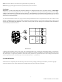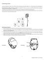
1
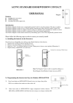
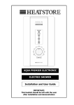
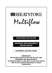
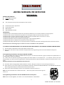
ADFW1 WIRELESS PIR DETECTOR
USER MANUAL
Wireless PIR Features
EXTRA Low current draw.
S.M.D. Technology.
12m, 110∘Convex honey comb, hemispherical infra-red lens.
Excellent false alarm suppression.
Pulse Count Facility.
Walk test LED.
High RFI & EMI Immunity.
Introduction
The Wireless PIR is a dual-element passive infra-red intrusion detector for use in wireless electronic security systems.
The Wireless PIR is easy to install by learning without connecting any cables from the Security Control Unit.
The Wireless PIR is compact, attractive and easy to install, it can be mounted indoors on a wall or in a corner.
The Wireless PIR is ideal for office and residential applications.
The Wireless PIR detects intrusion by determining changes in infra-red energy patterns.
The Wireless PIR emits no radiation and is harmless to humans & animals.
The Wireless PIR reduces false alarms to a very low level due to its effective elimination of background noises and nuisance alarms.
Please follow the following steps in order for correct installation and operation
1). DO NOT FIX THE DEVICES UNTIL ALL THE DEVICES HAVE BEEN LEARNT BY THE RECEIVER OR RADIO CONTROL PANEL
1. Do not install the radio devices until all the device has been learnt
1.2 Have all the radio devices ready marked for the appropriate zone programming with covers off and batteries ready to be
installed
2). Programming the detector into Easy Set Module APFW10
2.1 Press the (SW2) Learn button on APFW10 board for approx. 1-2 seconds And release, it gives one beeps and a yellow LED is on
to indicate learn mode, zone 1 flashing.
2.2 Select the zone required by pressing the (SW3) Zone Select Button to the desired zone. The relevant receiver zone LED
flashing slowly if no device has been programmed or flashing quickly device programmed (solid if 2 devices have been learnt on one
zone).
Warning: Two devices can be programmed on the same zone
3.1 Insert two “AAA” size high quality alkaline batteries as shown, taking care to observe correct polarity (Illustration 1).
3.2 If the receiver is still in learn mode once the batteries have been installed the APFW10 RED LED on the APFW10 will flash fast
twice and give two beeps to indicate that the device has been learnt.
3.3 Once learnt remove the battery and learn the next device and start at section 1.2
Note: The learn mode will time out after 10 seconds.
section 1.2
If the learn process times out start again at
3). Programming the detector into the APFWP wireless control panel
Illustration 1
AAA 1.5V
Note: Do not use rechargeable, zinc carbon or zinc chloride batteries in the detectors.
AAA 1.5V
1
ADFW1 Manual Rev 02- 20130103
Note: The wireless PIR has a 2 minute warm-up period after it is powered up.
Note: Before programming please familiarize yourself with the panel instructions
Final Setup
IMPORTANT – To extend the battery life, wireless PIR detectors are designed to detect once only before entering a “Sleep Mode”
condition for two minutes during which the unit will not trigger. Any movement seen by the PIR during this period causes “Sleep”
condition to be extended by a further two minutes, therefore, a wireless PIR which is constantly sensing movement, such as a person
walking around a room, may appear to be non-functional; you will find that the PIR will detect normally again following a two minute
period with no movement present.
The wireless PIR detector contains one jumper, which activates/deactivates the LED. If required that the LED will be off when the
detector is triggered during arm, pull this jumper off, otherwise, leave the jumper on. If you choose to leave the LED on, bear in mind
that this will reduce battery life (Illustration 2). This LED is normally used only walk testing to ensure the PIR covers the detection
area satisfactorily and then turned off.
1
Pulse count
3
3 1
LED ON
ON
LED
OFF
Illustration 2
If required, select the PIR LED “ON” or “OFF” option and the sensitivity (pulse count) by setting the corresponding jumpers on the electronic
module. Note that Pulse 1 option is more sensitive than the pulse 3 option. Pulse 1 option is used when it is necessary to activate an alarm on the
first detected pulse, or in high security installations – where fast “catch” performance is of greatest importance. Pulse 3 settings provide improved
protection against false alarms caused by all types of environmental disturbances. (Illustration2)
3). Power OFF the CU
Power OFF the CU completely after the Detector(s) have been learnt by isolating the backup power battery and mains supply (to
prevent the tamper function of the Detector(s) from triggering the alarm of the CU when mounting)
2
ADFW1 Manual Rev 02- 20130103
4). Mounting Location
2 - 2.5M
The PIR is designed for indoor use. It should not be mounted near large metal objects or on metal surfaces as this will effect the
performation of the radio transmission. It needs to be mounted on a wall or in a corner at a height of approximately 2-2.5meters
for the best general coverage in an average room.
The detector has been designed to avoid false alarms, nevertheless, it is best to avoid facing sources of heat such as fires and boilers,
and always try to keep away from a window. A PIR can look at a radiator but should not be sited above one.
Do not site a PIR where its field of view may be obstructed (e.g. by curtains). Also note that PIRs work best when sensing movement
across rather than along their detection beams.
Mounting the detector
1.
2.
3.
4.
Remove and retain the screw from the bottom of the PIR and lift off the cover. (Illustration 3)
If you are fitting the PIR in a corner, use mounting points ”A”, if you are fitting the detector on to a flat surface use mounting
points “B” – the mounting points are shown by indentations in the plastic molding. Use a small drill to create two fixing holes at
the mounting points (Illustration 4).
Hold the base of the PIR in the chosen position, ensuring that the front of PIR will face towards the centre of the protected area,
and mark and drill two 5mm fixing holes in the wall. DO NOT drill holes with the PIR in position – the resulting dust may damage
the unit. Secure the PIR to the wall using two screws (25mm countersink) and the wall plugs.
Replace the electronic module into the retaining clips, ensuring that it is correctly positioned and firmly seated. Install the
battery into the battery snap. Replace PIR cover and refit retaining screw.
A
Illustration 3
Illustration 4
B
3
ADFW1 Manual Rev 02- 20130103
5). Power the CU again
Power up the CU again. The system will return to standby ready for use.
Lens Arrays
Specifications
Type
Housing
Transmission range
Transmission frequency
Test LED
Mounting Height
Distance Range
Dual Element low noise Pyroelectric sensor
ABS
50 metres (open air with direct line of sight)
433MHz
Selectable (on/off)
2-2.5 m
Up to 12 meters
Power Supply
3Vdc (2 x 1.5V AAA Alkaline battery)
Battery Life
Approx. 18months
Due to our policy of continuous improvement we reserve the right to change specification without prior notice.
Errors and omissions accepted.
These instructions have been carefully checked prior to publication. However, no responsibility can be accepted by Challenger Security
Products for any misinterpretation of these instructions.
CHALLENGER SECURITY PRODUCTS
10 Sandersons Way
Blackpool
FY4 4NB
Sales Tel No: 0044 1253 791888
Technical No: 0044 1253 792 898
Email: [email protected]
Web: www.challenger.co.uk
4
ADFW1 Manual Rev 02- 20130103