1
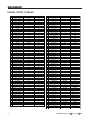
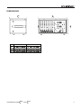
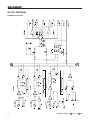
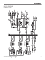
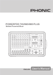
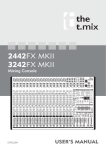
POWERPOD 620
PLUS
POWERPOD 740
PLUS
POWERED MIXERS
POWERPOD 620
PLUS
/740
PLUS
English
User’s Manual
POWERPOD 620
PLUS
/740
PLUS
POWER 620
POWER 740
PLUS
PLUS
POWERED MIXERS
TABLE OF CONTENTS
INTRODUCTION......................................................................................................................... 4
FEATURES.................................................................................................................................. 4
BASIC SETUP............................................................................................................................. 5
MAKING CONNECTIONS........................................................................................................... 6
CONTROLS AND SETTINGS..................................................................................................... 8
APPLICATION........................................................................................................................... 11
SPECIFICATIONS..................................................................................................................... 14
SPECIFICATIONS..................................................................................................................... 14
DIGITAL EFFECT TABLES....................................................................................................... 16
DIMENSIONS............................................................................................................................ 17
BLOCK DIAGRAMS.................................................................................................................. 18
Phonic reserves the right to improve or alter any information suppied within this document without prior notice.
V1.0 JAN 30, 2007
POWERPOD 620
PLUS
/740
PLUS
INTRODUCTION
FEATURES
Phonic Corp would like to congratulate you on the purchase
of one of their extraordinary Powerpod Mixers, powered
mixers that provide more than the average. Since its introduction, the entire Powerpod series has given other powered mixer lines a run for their money. With fantastically low
noise levels, high signal handling abilities, extraordinary
output levels, simplified signal routing abilities, and ultrasmooth controls, the Powerpods 620 and 740 Plus both
provide a level of dependability not often found in powered
mixers as of late.
POWERPOD 620 Plus
We know how eager you are to get started – getting the
mixer out and hooking all your gear up is probably your
number one priority right now – but before you do, we
strongly urge you to take a look through this manual. Inside, you will find important facts and figures on the set up,
use and applications of your brand new mixer. If you do
happen to be one of the many people who flatly refuse to
read user manuals, then we just urge you to at least glance
at the Instant Setup section. After glancing at or reading
through the manual (we applaud you if you do read the entire manual), please store it in a place that is easy for you to
find, because chances are there’s something you missed
the first time around.
● 120W + 120W / 4 ohms amplifier for main 1 / main 2 or
main / monitor (Bridge mono, 240W / 8 ohms)
● 32/40-bit digital stereo multi-effect processor with 100
programs plus foot switch
● Stereo 7-band graphic equalizers
● 6 balanced mic inputs through XLR jacks
● 8 line inputs through 1/4” jacks
● 2 Super Hi-Z inputs optimized for direct input of acous tic guitars and electric guitars or basses
● 2 built-in limiters
● 2-band channel EQ
● Pad control on channel 1~4
● Monitor and effect sends on each input channel
● 1 Aux input
● +48V phantom power
● Record outputwith trim control for recording level
matching
● Mains power switchable between 115VAC and
230VAC
POWERPOD 740 Plus
● 200W + 200W / 4 ohms amplifier for main L & R or main
/ monitor (Bridge mono, 440W / 8 ohms)
● 32/40-bit digital stereo multi-effect processor with 100
programs plus foot switch
● Dual 7-band graphic equalizers with In/Out switches for
main(stereo)/monitor or main L/R
● 7 balanced mic inputs through XLR jacks
● 10 line inputs through 1/4” jacks
● 2 Super Hi-Z inputs optimized for direct input of acous tic guitars and electric guitars or basses
● 2 built-in limiters
● 3-band channel EQ
● Pad control on channel 1~4
● Monitor and effect sends on each input channel
● 1 Aux input
● +48V phantom power
● Record output with trim control for recording level
matching
● Mains power switchable between 115VAC and
230VAC
POWERPOD 620
PLUS
/740
PLUS
BASIC SETUP
Getting Started
Channel Setup
1. Turn all power off on the Powerpod Mixer. To ensure
this, the AC cable should not be connected to the
unit.
1. To ensure the correct audio levels of each input channel is selected, every channel should first be switched
off and all faders set to 0.
2. All faders and level controls should be set at the lowest
level to ensure no sound is inadvertently sent through
the outputs when the device is switched on. All levels
should be altered to acceptable degrees after the device is turned on.
2. Choose the channel that you wish to set the level of,
and ensure that channel has a signal sent to it similar
to the signal that will be sent when in common use. For
example, if the channel is using a microphone, then
you should speak or sing at the same level the performer normally would during a performance. If a guitar is plugged into that channel, then the guitar should
also be used as it normally would be.
3. Plug all necessary instruments and equipment into the
device’s various inputs as required. This may include
line signal devices, as well as microphones and/or guitars, keyboards, etc.
NB. It is probably best to have nothing plugged into channels which
are not being set, just to ensure no signal is inadvertently sent
through the channel.
4. Plug any necessary equipment into the device’s various outputs. This could include speakers, monitors,
signal processors, and/or recording devices.
3. Set the gain so the level meter indicates the audio
level is around 0 dB.
NB. No devices other than speakers should be connected to the
power amp outputs. Plugging inappropriate devices into the
mixer will likely cause damage to the device. Also, guitar cables should not be used to connect amplifiers to speakers.
4. This channel is now ready to be used; you can stop
making the audio signal.
5. Plug the supplied AC cable into the AC inlet on the
back of the device, ensuring local voltage level is identical to that required on your device.
5. You should now select the next channel to set and go
back to follow steps 1 through 4.
6. Plug the supplied AC cable into a power outlet of a
suitable voltage.
7. Turn the power switch on.
POWERPOD 620
PLUS
/740
PLUS
MAKING CONNECTIONS
Master Section
Channel Inputs
4. AUX Inputs
This TS input connects the mixer with parallel external devices, such as sub mixers or external effect processors, receiving the processed signal from another
source and feeding it to the AUX mix.
The Powerpod 620 and 740 Plus Mixers supply various
numbers input channels. The 620 Plus features a total of 6
channels, 2 of which accept stereo signals. The 740 Plus,
on the other hand, features a total of 7 input channels, 3
of which accept stereo signals. Each channel features a
microphone XLR jack and at least one 1/4” Phone Jack
for balanced and unbalanced connections. Each stereo
channel features different inputs jacks, accepting either microphone inputs or stereo line inputs.
1. XLR Lo-Z Inputs
These combo jacks accept XLR microphone inputs.
They can be used in conjunction with microphones
such as professional condenser, dynamic or ribbon microphones with standard XLR male connectors. With
low noise preamplifiers, these inputs serve for crystal
clear sound replication.
NB. When using an unbalanced microphone, please ensure phantom power is switched off. However, when using condenser
microphones the phantom power of the corresponding channel should be activated.
5. Tape In (L and R)
The first of these inputs accommodates RCA cables
from such devices as tape and CD players. This allows for the inclusion of such devices as CD and MP3
players, as well as laptop computers, to the mixer. The
line from this feed is directed to the Tape In mix, before
being fed through to the Main L/R mixing bus.
6. Record Outputs (L and R)
As with the Tape In ports, these outputs will accommodate RCA cables, able to be fed the Main signal to
a variety of recording devices. The Powerpod 740 Plus
also includes a useful trim control, allowing for easy
level matching when recording.
2. 1/4” Hi-Z and Super Hi-Z Input Jacks
These inputs accept typical 1/4” TRS or TS unbalanced inputs. The Hi-Z inputs accept balanced TRS
inputs, and are for line-level devices with fairly low impedance (such as synthesizers and drum machines),
where the Super Hi-Z inputs accept TS unbalanced
sources, and can be used in conjunction with devices
with higher impedance levels (including electric guitars
and basses).
NB. When using a line-level device on your mixer, the PAD -25
button should be engaged.
3. Stereo Channel Inputs
The Powerpod 740 Plus Powered Mixers provide 3
stereo input channels, and the Powerpod 620 Plus
features 2 – the inputs of which differ slightly to the
mono channels. The 3-pin XLR inputs featured are
for the addition of microphones with typical XLR male
inputs, where the 2 Line 1/4” TS jacks are for the addition of various stereo line level input devices, such
as keyboards. If you wish to use a monaural device
on a stereo return input, simply plug the device’s 1/4”
phone jack into the left (mono) stereo input and leave
the right input bare. The signal will be duplicated to the
right.
7. Foot Switch Jacks
The foot switch jack allows the user to remotely turn
the digital effects on and off.
8. EFX (Effect) Outputs
These 1/4” TS outputs are the final output from the
EFX send mixing bus. This feed may be used to connect to an external digital effect processor, or even to
an amplifier and speakers, depending on your desired
settings.
POWERPOD 620
PLUS
/740
PLUS
9. Monitor Outputs
These 1/4” TS outputs are the final output from the
Monitor send mixing bus. This feed may be used to
connect to an amplifier and speaker. Feeding the output from the Monitor out to an amplifier (and possibly
an equalizer) and then to a floor monitor speaker allows artists to monitor their own instruments or vocals
whilst performing, or an engineer to monitor the mix.
Not used
10. Main Outputs
This output will send the final stereo line level signal
from the main mix. The primary purpose of these jacks
is to send the Main signal to external devices that may
run in parallel with the mixer. This may include additional power amplifiers, other mixers, PA systems, as
well as a wide range of other possible signal processors.
Not used
Rear Panel
11. Speaker Outputs
These jacks are used to connect to speakers, fed from
the internal power amp. Both the Powerpod 620 and
740 Plus feature 1/4” phone jacks. The Amp Select
switch determines the operation of these jacks. If the
Amp Select switch is set to “Moni / Main” or “Main 1 /
Main 2” a single speaker with a 4 to 8 ohm load can
be connected to jack A on both the Main 1 and Main 2
speaker outputs, or two speakers with a load between
8 and 16 ohms can be connected to both jacks A and
B. When using Bridge Mono mode, use the speaker
output labeled “(L+R) Bridge” only to connect a speaker with a loading between 8 and 16 ohms. Refer to
the Speaker set up chart to the right for more detailed
Indication of how to connect speakers.
Not used
Not used
NB. Due to the fact that the signal has been processed by the
power amp, these ports should be used in conjunction with
passive speakers only to avoid damaging any other equipment.
POWERPOD 620
PLUS
/740
PLUS
CONTROLS AND SETTINGS
Channel Controls
12. HF (High Frequency) Control
This control is used to give a shelving boost or cut of
±15 dB to high frequency (12 kHz) sounds. This will
adjust the amount of treble included in the audio of
the channel, adding strength and crispness to sounds
such as guitars, cymbals, and synthesizers.
13. MF (Middle Frequency) Control (Powerpod 740
Plus only)
This control is used to provide a peaking style of boost
and cut to the level of middle frequency sounds at a
range of ±15 dB. Changing middle frequencies of an
audio feed can be rather difficult when used in a professional audio mix, as it is usually more desirable to
cut middle frequency sounds rather than boost them,
soothing overly harsh vocal and instrument sounds in
the audio.
14. LF (Low Frequency) Control
This control is used to give a shelving boost or cut of
±15 dB to low frequency (80 Hz) sounds. This will adjust the amount of bass included in the audio of the
channel, and bring more warmth and punch to drums
and bass guitars.
15. MONI (Monitor) Level Control
This control alters the signal level that is being sent to
the Monitor mixing buses, the signal of which is suitable for connecting stage monitors, allowing artists to
listen to the music that is being playing.
16. EFX (Effect) Level Control
This control alters the signal level that is sent to the
EFX output, which can be used in conjunction with
external signal processors (this signal of which can
be returned to mixer via the stereo return inputs), or
simply as additional auxiliary outputs for any means
required. These controls also adjust the level of audio
that is sent to the built-in digital effect panel.
17. Channel Level Control
This control will alter the signal level that is sent from
the corresponding channel to the Main mixing bus.
18. PAD -25 Button
The PAD -25 button (located above the 1/4” Phone
Jack of mono channels) is used to attenuate the input
signal by 26 dB. This should only be pushed in when
using line-level input devices.
Digital Effect Processor
19. Digital Effect Display
This 2-digital numeric display shows the program number that is currently applied to your EFX audio signal.
When you rotate the Program control, you can scroll
through different program numbers; however the display will revert back to the original program if a new
program is not selected within a few seconds.
20. Sig and Clip Indicators
Located within the Digital Effect Display are Clip and
Sig LEDs. The Sig LED will light up when any signal
is received by the effect processor, and the Clip LED
will light up shortly before excessive signals are dynamically clipped. If the Clip LED lights up too often, it
may be advisable to turn down one or all EFX controls
on input channels to ensure the signal level is not too
high.
21. Program Control
This control is used to scroll through the various effects. Turning the control clockwise will allow users
to ascend into higher program numbers, and turning
it counter-clockwise will allow users to descend into
lower program numbers. Pushing this control will apply the new effect. When a tap-delay effect is selected,
pressing this control will allow users to select the tapdelay time.
By pushing the button several times, the effect processor interprets the time between last two pushes
and remembers this as the delay time, until the button is pushed again (this is kept, even after the power
is turned off). When the tap delay effect is selected,
a small LED will flash within the digital effect display
window at the selected intervals.
POWERPOD 620
PLUS
/740
PLUS
Master Section
22. EFX Return Control
The Powerpod 620 Plus features a single EFX Return
control that adjusts the level of the EFX return input
that is sent to the Main mix. The Powerpod 740 Plus,
on the other hand, features two EFX Return controls;
one that adjusts the level that is sent to the Monitor (or
Main 2) mix, another that controls the final level that is
sent to the Main (or Main 1) mix.
26. EQ IN and Indicator
(Powerpod 740 Plus only)
This button activates the equalizer in which it accompanies. The corresponding LED indicator illuminates
when the EQ is activated.
27. EQ Select Switch
(Powerpod 740 Plus only)
This switch (featured on the Powerpod 740 Plus only)
enables you to select the way you utilize the pair of
Equalizers on these models. When the switch is in the
uppermost position it enables you to use the top equalizer for the Monitor signal and the lower equalizer for
the Main mix. In the lower position, the equalizers are
used for the mixer’s Main 1 and 2 signals.
28. Phantom Power Switch and Indicator
When this switch is in the on position it activates +48V
of Phantom Power for all channels on the Powerpod
Mixers, allowing condenser microphones to be used
on these channels. The corresponding LED will illuminate when the Master Phantom Power is activated.
23. AUX In Control
This control allows users to adjust the level of the AUX
input signal that is sent to the Main stereo mix.
24. Tape In
The Powerpod 620 Plus features a single Tape in control (located below the equalizer) that adjusts the level
of the AUX in input that is sent to the Main 1-2 mix. The
Powerpod 740 features a Tape in control for both the
Monitor and Main L-R channels, with a single control
located below each of the equalizers.
29. Amp Select Switches
This switches control the activity of the built-in power
amp, enabling the user to alternate between the different signals which can be processed by the builtin power amp and routed to the speaker outputs on
the rear of the device. This switch allows you to select from: Main/Monitor – taking the monitor and main
signals and directing them to the appropriate outputs
– Main 1 / Main 2 – taking the Main signals to send to
– and Bridge (L+R) – which combines the Main Left
and Right signal and feeds them through the (L+R)
Bridge output.
NB. When using a mono bridge connection, use the (L+R) Bridge
speaker jack only. Connecting speakers to the other speaker
outputs could cause irreversible damage to the unit.
25. Graphic Equalizers
These graphic equalizers allow users to adjust the frequency response of a signal, with a maximum of ±12
dB of signal boost or cut for each of the frequencies.
The Powerpod 620 features a single 7-band equalizer.
The Powepod 740 Plus features dual 7-band Graphic
Equalizers (for the Moni/Main 2 and Main/Main 1 signals).
POWERPOD 620
PLUS
/740
PLUS
30. Monitor Level Control
This rotary control allows the user to adjust the final
signal level sent to all Monitor outputs.
31. Main Level Control
This rotary control allows the user to adjust the final
signal level sent to the Main L-R and Speaker outputs.
32. Level Meter
These level meters give accurate indications of when
audio levels of the Main and Monitor outputs reach
certain levels. The 0 dB indicator illuminates is approximately equal to an output level of +4 dBu. It is
suggested that users set the various levels controls
so that it sits steadily between 0 and the second highest level indicated on the Level Meter to make full use
of audio, while still maintaining great clarity. The 620
Plus features a dual 5-segment LED display, whereas
the 740 Plus features two separate 5-segment LED
displays.
33. Limiters Indicators (Powerpod 740 Plus only)
These LED indicators illuminate when the power amplifier’s built-in limiters are activated, which effectively
reduce signal levels when they reach high levels that
could prove to damage sound quality.
Rear Panel
35. Power Button
The power button, located on the rear of the mixer, is
used to activate the mixer.
36. AC Power Connector / Cord
The AC connector on the Powerpod 740 Plus is included to ensure your Mixer gets the power it needs.
Please use the power cable that is included with this
mixer only. Located just below the AC power connector is the power supply’s fuse. If the fuse ever blows,
users are advised to switch it with a new fuse that corresponds with the specs listed on the fuse cover. The
Powerpod 620 Plus has permanently connected AC
power cord.
34. Power Indicator
This LED indicator illuminates when power of your
Powerpod Mixer is activated.
37. Voltage Selector Switch (Powerpod 740 Plus only)
This switch helps to adapt the mixer to different Countries’ AC voltage levels. It is advised that users check
that this switch’s settings match your area’s voltage
levels before attempting to operate the unit.
10
POWERPOD 620
PLUS
/740
PLUS
APPLICATION
POWERPOD 620 Plus
VOCAL
VOCAL
MICROPHONE
SIDE FILL
R ACTIVE SPEAKE
OR ANOTHER PA SYSTEM
GUITAR AMP
ELECTRIC GUI
TAR
MICROPHONE
PC
POWERPOD 620
PLUS
/740
PLUS
11
APPLICATION
POWERPOD 620 Plus
DRUM MACHINE
VOCAL
VOCAL
DAT RECORDER
12
POWERPOD 620
PLUS
/740
PLUS
APPLICATION
POWERPOD 740 Plus
ACTIVE SPEAKER
DRUM MACHINE
MICROPHONE
ELECTRIC GUITAR
BASS
PC
POWERPOD 620
PLUS
/740
PLUS
13
SPECIFICATIONS
Powerpod 620 Plus
Power Amplifier
Inputs
Outputs
Channel Strips
Master Section
Power Channels
2
2
Limiters
2 (without LED INDICATORS)
2
8-Ohm Load per Channel
80 Watts
145 Watts
4-Ohm Load per Channel
120 Watts
220 Watts
4-Ohms Bridged Mono
240 Watts
440 Watts
Mono Mic/Line Channels
6
7
Super Hi-Z Inputs
2
2
Tape in
Stereo RCA
Stereo RCA
Aux Returns
1
1
Speaker Outputs
5 TRS 1/4”
5 TRS 1/4”
Main Mix (Line) Level
1 TRS 1/4”
1 TRS 1/4”
Aux Sends
1 Monitor
1 Monitor
Record Output
Stereo RCA
Stereo RCA (with trim)
Total Channel Strips
6
7
Monitor/Effect Send Controls
2
2
Volume Controls
Rotary
Rotary
PAD In/Out
4
4
Aux Send Masters
1 Monitor
1 Monitor
Aux Returns
1
1
Effects Return
N/A
2
Faders
Rotary (Main)
Rotary (Main)
Level Meter
5-segment
5-segment
+48V (global switch)
+48V (global switch)
100
100
Effect Processor 1 Controls
1 program selector
1 program selector
Foot Switch
On/Off
On/Off
Type
2-band
3-band
Range
+/-15 dB
+/-15 dB
Low
80 Hz
80 Hz
Mid
N/A
2.5KHz
High
12 KHz
12 KHz
Master
7-band
2X 7-band (Assignable
to Main1/Main2)
Center Frequencies
60,120, 360, 1K, 2.5K, 7K,
16KHz
60,120, 360, 1K, 2.5K,
7K, 16KHz
Range
+/-12 dB
+/-12 dB
20Hz~20KHz, line level o/p
@ +4 dBu into 600 ohms
+0/-2 dB
+0/-2 dB
20Hz~20KHz, power amp
o/p 1 Watt into 8 ohms
+0/-2 dB
+0/-2 dB
Adjacent inputs or input to
output
<-90 dB
<-90 dB
Phantom Power Supply
Digital Effects (DFX)
Channel Equalizer
Graphic Equalizer
Frequency Response
Crosstalk (@ 1 KHz)
14
Powerpod 740 Plus
Programs
POWERPOD 620
PLUS
/740
PLUS
Noise
Total Harmonic Distortion (THD)
Maximum Level
Power Supply
Master fader down
<-78 dBu
<-78 dBu
Master fader 0 dB, ch. faders down
<-63 dBu
<-63 dBu
Mic input to main mix output
@ +14 dBu
<0.5%, 4 ohms, @60 Watts
<0.5%, 4 ohms, @60
Watts
Any output, 1KHz
@+14dBu, 20Hz~20KHz,
channel inputs
<0.3%
<0.3%
Mic Preamp Input
+10 dBu
+10 dBu
All Other Inputs
+22 dBu
+22 dBu
Unbalanced Outputs
+22 dBu
+22 dBu
Mains Voltage
115VAC~230VAC, 50/60 Hz,
Switchable
115VAC~230VAC, 50/60
Hz, Switchable
Power Consumption
120 Watts
220 Watts
Dimensions (W x H x D)
440x245x275mm (17.3” x 9.6”
x 10.8”)
471x265x275mm (18.5”
x 10.4” x 10.8”)
Weight
27.5 lbs
29.7 lbs
12.5 kg
13.5 kg
POWERPOD 620
PLUS
/740
PLUS
15
DIGITAL EFFECT TABLES
NO
PARAMETER SETTING
ROOM
REV-TIME
EARLY LEVEL
00
COMPACT ROOM 0.05
00
0
COMPACT ROOM 2
0.4
02
SMALL ROOM 0
SMALL ROOM 2
04
05
NO
PROGRAM NAME
PARAMETER SETTING
PAN
SPEED
56
SLOW PAN
0.
R-->L
0
57
SLOW PAN 0.
R<-->L
0.45
00
58
SLOW PAN 2
0.4
R-->L
0.6
90
59
MID SHIFT
0.8
R<-->L
MID ROOM 0.9
00
60
MID SHIFT .2
L-->R
MID ROOM 2
50
6
MID SHIFT 2
.8
L-->R
06
BIG ROOM .2
00
62
MID SHIFT .8
R-->L
07
TUNNEL
.85
00
6
FAST MOVE
.4
R<-->L
HALL
REV-TIME
EARLY LEVEL
TREMOLO
SPEED
MODE-TYPE
08
JAZZ CLUB
0.9
90
64
LAZY TREMOLO
0.8
TYPE
TRG
09
SMALL HALL .5
72
65
VINTAGE TREMOLO
.5
TRG
0
SMALL HALL 2
.75
85
66
WARM TREMOLO
2.8
TRG
SPRING HALL
.9
98
67
WARM TREMOLO 4.6
TRG
2
MID HALL 2.
00
68
HOT TREMOLO
6.8
TRG
MID HALL 2
2.45
80
69
HOT TREMOLO 9.6
TRG
4
RECITAL HALL
2.7
96
70
CRAZY TREMOLO 5
TRG
5
BIG HALL 2
.
88
7
CRAZY TREMOLO 2
20
PLATE
REV-TIME
HPF
DELAY+REV
REV
TRG
DELAY-1
6
SMALL PLATE
0.9
0
72
DELAY+REV 7
TAIL PLATE
.2
20
7
DELAY+REV 2
2
2
8
MID PLATE .
0
74
DELAY+REV 9
MID PLATE 2
2.2
0
75
DELAY+REV 4
4
4
20
REVERSE PLATE
2.25
42
76
DELAY+REV 5
5
5
2
LONG PLATE 2.6
80
77
DELAY+REV 6
6
6
22
LONG PLATE 2
625
78
DELAY+REV 7
7
7
2
LONG PLATE 4.2
0
79
DELAY+REV 8
8
8
DELAY-1(stereo)
DELAY AVERG.
R-LEVEL
CHORUS+REV
REV
CHORUS
24
SHORT DELAY 0.07
60
80
CHORUS+REV 25
SHORT DELAY 2
0.4
60
8
CHORUS+REV 2
2
2
26
PING PONG DELAY
0.
55
82
CHORUS+REV 27
MID DELAY 0.5
55
8
CHORUS+REV 4
4
4
28
16
PROGRAM NAME
0.
60
84
CHORUS+REV 5
5
5
29
SHORT DELAY (MONO)
MID DELAY 0.06
00
85
CHORUS+REV 6
6
6
0
MID DELAY (MONO)
0.
00
86
CHORUS+REV 7
7
7
LONG DELAY (MONO)
0.8
00
87
CHORUS+REV 8
8
8
CHORUS
LFO
DEPTH
FLANGER+REV
REV
FLANGER
2
SOFT CHORUS
0.2
56
88
FLANGER+REV SOFT CHORUS 2
0.5
70
89
FLANGER+REV 2
2
2
4
SOFT CHORUS 0.8
75
90
FLANGER+REV 5
WARM CHORUS
.8
85
9
FLANGER+REV 4
4
4
6
WARMER CHORUS .2
80
92
FLANGER+REV 5
5
5
7
WARMER CHORUS 2
5.2
45
9
FLANGER+REV 6
6
6
8
WARMER CHORUS 7.8
52
94
FLANGER+REV 7
7
7
9
HEAVY CHORUS
9.6
48
95
FLANGER+REV 8
8
8
FLANGER
LFO
DEPTH
GATED-REV
RELEASE
REV
40
CLASSIC FLANGER 0.
44
96
GATED-REV- 9
0.02
TAIL PLATE
4
CLASSIC FLANGER 2
0.
6
97
GATED-REV-2 0
0.2
TAIL PLATE
42
GENTLE FLANGER
0.6
45
98
GATED-REV- 9
0.02
REVERSE PLATE
4
WARM FLANGER
.6
60
99
GATED-REV-2 0
0.5
REVERSE PLATE
44
MODERN FALANGER 2
85
TAP DELAY
FB LEVEL
RANGE
45
MODERN FALANGER 2
2.8
80
A0
TAP DELAY
0
00mS - 2.7S
46
DEEP FALANGER 4.6
75
A
TAP DELAY
0
00mS - 2.7S
47
DEEP FALANGER 2
0
60
A2
TAP DELAY
20
00mS - 2.7S
PHASER
LFO
DELAY
A
TAP DELAY
0
00mS - 2.7S
48
CLASSIC PHASER 0.
.6
A4
TAP DELAY
40
00mS - 2.7S
49
CLASSIC PHASER 2
0.4
2.6
A5
TAP DELAY
50
00mS - 2.7S
50
COOL PHASER
.4
0.7
A6
TAP DELAY
60
00mS - 2.7S
5
WARM PHASER
.2
0.
A7
TAP DELAY
70
00mS - 2.7S
52
HEAVY PHASER 5
.2
A8
TAP DELAY
80
00mS - 2.7S
5
HEAVY PHASER 2
6
2.8
54
WILD PHASER 7.4
0.8
T0
55
WILD PHASER 2
9.6
4.8
T
T2
PN
PINK NOISE
20Hz~20kHz
TEST TONE
LOW FREQUENCY
FREQUENCY
SHAPE
00Hz
SINEWAVE
MID FREQUENCY
kHz
SINEWAVE
HIGH FREQUENCY
0kHz
SINEWAVE
POWERPOD 620
PLUS
/740
PLUS
DIMENSIONS
POWERPOD 620 PLUS
POWERPOD 620
PLUS
/740
POWERPOD 740 PLUS
PLUS
17
BLOCK DIAGRAM
POWERPOD 620 Plus
18
POWERPOD 620
PLUS
/740
PLUS
BLOCK DIAGRAM
POWERPOD 740 Plus
POWERPOD 620
PLUS
/740
PLUS
19
TO PURCHASE ADDITIONAL PHONIC GEAR AND ACCESSORIES
To purchase Phonic gear and optional accessories, contact any authorized Phonic distributor. For
a list of Phonic distributors please visit our website at www.phonic.com and click on Get Gear. You
may also contact Phonic directly and we will assist you in locating a distributor near you.
SERVICE AND REPAIR
Phonic has over 100 service centers worldwide. For replacement parts, service and repairs please
contact the Phonic distributor in your country. Phonic does not release service manuals to
consumers, and advice users to not attempt any self repairs, as doing so voids all warranties. You
can locate a dealer near you at www.phonic.com.
WARRANTY INFORMATION
Phonic stands behind every product we make with a no-hassles warranty. Warranty coverage
may be extended, depending on your region. Phonic Corporation warrants this product for a
minimum of one year from the original date of purchase against defects in material and workmanship under use as instructed by the user’s manual. Phonic, at its option, shall repair or replace the
defective unit covered by this warranty. Please retain the dated sales receipt as evidence of the
date of purchase. You will need it for any warranty service. No returns or repairs will be accepted
without a proper RMA number (return merchandise authorization). In order to keep this warranty
in effect, the product must have been handled and used as prescribed in the instructions accompanying this warranty. Any tempering of the product or attempts of self repair voids all warranty.
This warranty does not cover any damage due to accident, misuse, abuse, or negligence. This
warranty is valid only if the product was purchased new from an authorized Phonic
dealer/distributor. For complete warranty policy information, please visit http://www.phonic.com.
CUSTOMER SERVICE AND TECHNICAL SUPPORT
We encourage you to visit our online help at http://www.phonic.com/help/. There you can find
answers to frequently asked questions, tech tips, driver downloads, returns instruction and other helpful
information. We make every effort to answer your questions within one business day.
Phonic America Corporation
6103 Johns Road, #7
Tampa, FL 33634
(813) 890-8872
[email protected]
http://www.phonic.com