1
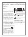
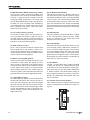
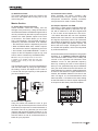
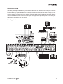
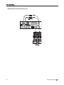
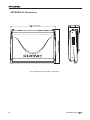
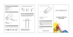
POWERPOD K16
POWERED MIXER
PLUS
IMPORTANT SAFETY INSTRUCTIONS
The apparatus shall not be exposed to dripping or splashing and that no objects
with liquids, such as vases,
shall be placed on the apparatus. The MAINS plug is used as the disconnect device, the disconnect device shall
remain readily operable.
Warning: the user shall not place this apparatus in the
can be easily accessible.
area during the operation so that the mains switch
1. Read these instructions before operating this
apparatus.
CAUTION
2. Keep these instructions for future reference.
RISK OF ELECTRIC SHOCK
DO NOT OPEN
3. Heed all warnings to ensure safe operation.
4. Follow all instructions provided in this document.
5. Do not use this apparatus near water or in locations
where condensation may occur.
6. Clean only with dry cloth. Do not use aerosol or liquid
cleaners. Unplug this apparatus before cleaning.
7. Do not block any of the ventilation openings. Install
in accordance with the manufacturer’s instructions.
8. Do not install near any heat sources such as radiators,
heat registers, stoves, or other apparatus (including
.
9. Do not defeat the safety purpose of the polarized or
grounding-type plug. A polarized plug has two blades
with one wider than the other. A grounding type plug
has two blades and a third grounding prong. The wide
blade or the third prong is provided for your safety. If
the provided plug does not into your outlet, consult
an electrician for replacement of the obsolete outlet.
10. Protect the power cord from being walked on or
pinched particularly at plug, convenience receptacles,
and the point where they exit from the apparatus.
11. Only use attachments/accessories
manufacturer.
by the
12. Use only with a cart, stand, tripod, bracket, or
table
by the manufacturer, or sold with
the apparatus. When a cart is used, use caution
when moving the cart/apparatus
combination to avoid injury from tipover.
13. Unplug this apparatus during lighting
storms or when unused for long
periods of time.
14. Refer all servicing to
service personnel.
Servicing is required when the apparatus has been
damaged in any way, such as power-supply cord or
plug is damaged, liquid has been spilled or objects
have fallen into the apparatus, the apparatus has
been exposed to rain or moisture, does not operate
normally, or has been dropped.
CAUTION: TO REDUCE THE RISK OF ELECTRIC SHOCK,
DO NOT REMOVE COVER (OR BACK)
NO USER SERVICEABLE PARTS INSIDE
REFER SERVICING TO QUALIFIED PERSONNEL
The lightning flash with arrowhead symbol, within an
equilateral triangle, is intended to alert the user to the
presence of uninsulated “dangerous voltage” within the
product’
magnitude to constitute a risk of electric shock to persons.
The exclamation point within an equilateral triangle is intended to alert the user to the presence of important operating and maintenance (servicing) instructions in the literature
accompanying the appliance.
WARNING: To reduce the risk of
or electric shock, do
not expose this apparatus to rain or moisture.
CAUTION: Use of controls or adjustments or performance
of procedures other than those
may result in
hazardous radiation exposure.
POWERPOD K16
PLUS
Powered Mixer
INTRODUCTION............................................................................................4
FEATURES. . . . . . . . . . . . . . . . . . . . . . . . . . . . . . . . . . . . . . . . . . . . . . . . . . . . . . . . . . . . . . . . . . . . . . . . . . . . . . . . . . . . . . . . . . . . . . . . . . 4
BASIC SETUP...............................................................................................5
Getting Started..........................................................................................5
Channel Setup..........................................................................................5
The Protective Molded Cover..........................................................................6
MAKING CONNECTIONS..................................................................................7
Channel Inputs..........................................................................................7
Master Section..........................................................................................7
Rear Panel..............................................................................................8
CONTROLS AND SETTINGS.............................................................................. 9
Powering the Unit.......................................................................................9
Digital Effects Panel...................................................................................11
Master Section.........................................................................................12
APPLICATIONS. . . . . . . . . . . . . . . . . . . . . . . . . . . . . . . . . . . . . . . . . . . . . . . . . . . . . . . . . . . . . . . . . . . . . . . . . . . . . . . . . . . . . . . . . . . 1 5
Live Application.......................................................................................15
Adding External Parallel Devices... .................................................................16
SPECIFICATIONS. . . . . . . . . . . . . . . . . . . . . . . . . . . . . . . . . . . . . . . . . . . . . . . . . . . . . . . . . . . . . . . . . . . . . . . . . . . . . . . . . . . . . . . . 17
APPENDIX A: Digital Effect Table........................................................................19
APPENDIXB: Dimensions................................................................................20
APPENDIX C: Typical Connecting Leads...............................................................21
APPENDIX D: Block Diagram.............................................................................2 2
Phonic preserves the right to improve or alter any information within this document without prior notice.
V1.0 DEC 8,2006
INTRODUCTION
FEATURES
Thank you for your purchase of the Powerpod
K-16 Plus Powered Mixer. The K-16 Plus is of a
high standard of quality that is synonymous with
all of Phonic’s products and is sure to be a valuable investment. To ensure, however, that you
take full advantage of this product, we advise
you to carefully read the entire manual before
storing in a place that is easy to remember and
easy to access if necessary.
• 500W + 500W / 4 Ohms stereo power amplifier
(bridgeable and patchable)
We know how eager you are to get started –
wanting to get the mixer out and hook it all up
is probably your number one priority right now
- but before you do, we strongly urge you to take
a look through this manual. Inside you will find
important facts and figures on the set up, use
and applications of your brand new mixer. If you
do happen to be one of the many people who
flatly refuse to read users manuals, then we urge
to at least glance at the Instant Setup section.
After looking through the manual (we applaud if
you do read the entire manual ), please store it
n a place that is easy to find for you, because
chances are there is something you missed the
first time around.
• Dual DFX, our 32/40-bit digital multi-effect processor with 100 programs plus tap control, Test
tone generator and foot switch on/off jack
• 12 balanced Mic inputs with inserts
• Total of 16 Line inputs
• Two stereo Line input channels capable of accepting RCA/Phone inputs
• 3-band channel EQ with swept mid-range
• Stereo 7-band graphic EQ with Feedback
Detection
• Four AUX sends, where AUX 2 can be set to
pre or post fader
• Two stereo AUX returns, each can be routed to
AUX 1 & 2 sends (effect to monitor)
• Stereo RCA I/O for CD/TAPE external sources
• Vocal Eliminator
• Solid Phonic System speaker enhancement
• Grouped +48V real phantom power for broader
application
• Mono output for extra zone filling or as subwoofer processing source
• PFL on each input and AFL on each output
• Standby switch to mute Ch1~Ch12 for playing
music between sets
• Zone 2 output for side fill or another PA system
• Headphone/control room output with rotary level control
• One professional Speakon-type jack and two
1/4" jacks per channel for speaker connection
• Rugged metal main chassis with integrated
handle
• Less weight achieved by high-efficiency switching power supply
• Optional molded protective cover prevents
scratching or damage to mixer
• Mains power switchable between 115 VAC and
230 VAC
PLUS
POWERPOD K16 Plus
BASIC SETUP
Getting Started
1. Ensure all power is turned off on the Powerpod K-16 Plus. To totally ensure this, the AC
cable should not be connected to the unit.
2. All faders and level controls should be set at
the lowest level and all channels switched
off to ensure no sound is inadvertently
sent through the outputs when the device
is switched on. All levels should be altered
to acceptable degrees after the device is
turned on.
3. Ensure that the rear of the mixer is not less
than 30 centimeters from the wall, as being
closer than that may obstruct the cooling
fans and cause overheating.
4. Plug all necessary instruments and equipment into the device’s various inputs as required. This may include line signal devices,
as well as microphones and/or guitars, keyboards, etc.
5. Plug any necessary equipment into the device’s various outputs. This could include
speakers, monitors, signal processors, and/
or recording devices. No devices other than
speakers should be connected to the power
amp outputs. Plugging inappropriate devices into the mixer will likely cause damage to
the device. Also, guitar cables should not be
used to connect amplifiers to speakers.
Channel Setup
1. To ensure the correct audio levels of each
input channel is selected, every channel
should first be switched off and all faders set
to 0.
2. Choose the channel that you wish to set the
level of, and ensure that channel has a signal sent to it similar to the signal that will be
sent when in common use. For example, if
the channel is using a microphone, then you
should speak or sing at the same level the
performer normally would during a performance. If a guitar is plugged into that channel, then the guitar should also be used as it
normally would be.
3. Press the PFL button of the channel, allowing you to see the audio level in the master
level meter.
4. Set the gain so the level meter indicates the
audio level is around 0 dB.
5. This channel is now ready to be used; you
can stop making the audio signal.
6. To activate the channel, release the PFL button and engage the channel’s on button.
7. You should now select the next channel to
set and go back to follow steps 1 through 6.
6. Plug the supplied AC cable into the AC inlet
on the back of the device.
7. Plug the supplied AC cable into a power outlet of a suitable voltage.
8. Turn the power switch on.
POWERPOD K16
PLUS
The Protective Molded Cover
Opening the cover
pull up to open.
Removing the cover
Attaching the cover
Place the small connecting rods of the
molded cover underneath the mixer's
hooks.
PLUS
POWERPOD K16 Plus
MAKING CONNECTIONS
Master Section
Channel Inputs
4. Tape Inputs
These inputs accommodate RCA connections from such devices
as tape and CD players.
The line from this feed is
directed to the Tape In
mixing bus, before being
fed through to the Main
L/R mixing bus.
1. Combo Jack Inputs
These inputs are for balanced and unbalanced
signals, accepting both
XLR and 1/4” line inputs.
They can be used in conjunction with microphones
– such as professional
condenser, dynamic or
ribbon microphones with standard XLR male
connectors, or various
music instruments – such
as
keyboards,
drum
machines, electric guitars,
etc – with 1/4” TS or TRS
connectors.
NB. When using an unbalanced microphone, please ensure
phantom power is switched off. However, when using condenser microphones the phantom power of the corresponding channel should be activated.
2. INS (External Device Insert Jack)
The primary use for these TRS phone jacks is for
the addition of external devices, such as dynamic processors or equalizers, to the corresponding
mono input channel. This will require a Y cord
that can send and receive signals of the mixer to
and from an external processor.
3. Stereo Channel Inputs
(Channels 13/14 15/16)
The Powerpod K-16 Plus powered mixer provides 2 pairs
of stereo input channels, the
inputs of which differ slightly
to the mono channels. Each
stereo channel provides 1/4”
TRS line inputs that can be
used to connect external devices with professional line
level signals (+4dBu) like CD or DAT players or
external signal processor. In addition to this, two
pairs of stereo RCA line inputs are included for
maximum flexibility, allowing consumer level CD
and tape players to be used. In order to receive
the signal from the RCA inputs you should place
the A/B selector switch should be pushed in.
NOTE: Both the stereo 1/4” TRS and stereo RCA inputs are
‘linked’ and therefore cannot be used simultaneously.
POWERPOD K16
PLUS
5. Vocal Eliminator
Initiating this switch enables you to eliminate
vocal sections of any signal fed from a CD or
tape player into the Tape In inputs. Using phase
cancellation of vocal frequency ranges between
the left and right channel, the K-16’s vocal eliminator can effectively remove vocals panned
dead centre.
6. Record Outputs
As with the Tape Inputs, these outputs will accommodate RCA connectors, able to be fed to a
variety of recording devices.
7. Stereo Return Inputs
These TS inputs connect the mixer with parallel
external devices, such as sub mixers or external
effect processors, receiving the processed signal
from another source and feeding it to the AUX 1,
AUX 2 and Main L/R mixing buses.
8. Power Amp Inputs
These inputs support 1/4” TS plugs and can be
used for the inclusion of external line level signals to the built-in power amplifier. If a device
is connected to the power amp inputs, the main
feed (according to the power amp control switch)
will automatically bypass the power amp and the
inserted feed will be amplified and sent to the
Speaker Outputs instead.
9. Main Outputs
These two outputs will send the final stereo line
level signal from the main mixing bus. The primary purpose of these jacks is to send the Main
output to external devices that may run in parallel
with the mixer. This may include additional power
amplifiers, mixers, PA systems, as well as a wide
range of other possible signal processors.
10. AUX 1 and 2 Outputs
These phone jack outputs are the final output
of line-level signal fed from the corresponding
auxiliary mixing bus, and are best suited for use
with stage monitors. Feeding the output from the
Auxiliary outs to an amplifier – and possibly an
equalizer – and then to a floor monitor speaker
allows artists to monitor their own instruments or
vocals whilst performing.
Rear Panel
11. EFX 1 and 2 Outputs
These 1/4” TS outputs are the final output from
the EFX send mixing bus. This feed may be used
to connect to an external digital effect processor,
or even to an amplifier and speakers, depending
on your desired settings.
NB. Due to the fact that the signal has been processed by
the power amp, these ports should be used in conjunction
with passive speakers only to avoid damaging any other
equipment.
12. Control Room / Zone 2 Outputs and
Switch
These phone jack outputs feed a dry signal from
either the Control Room or Zone 2 control panels, as selected by the accompanying switch.
The Zone 2 signal is best suited to act as “side
fill,” supplying audio to indoor areas that the
sound from the main speakers does not reach. The
control room’s signal, on the
other hand, can be used for
the inclusion of an active
monitor within a booth. Well,
they’re our suggestions, but
it’s your call.
15. Speaker Outputs
Use this jacks to connect your speakers, fed
from the internal power amp. The first set of outputs are XLR connectors; to use these, insert an
appropriate 3-pin XLR plug into the connector.
The second set of outputs are 1/4” phone jacks;
to use these, simply insert an appropriate 1/4”
TS plug into them.
Using speakers with an incorrect loading can not
only cause distortion, but also irreversible damage to the powered mixer. Please ensure the
loadings of your speakers are consistent with
those shown above.
16. Footswitch Jack
By connecting a typical nonlatching footswitch to this jack,
users can turn the K-16 Plus’s
built-in digital effect processor on
and off.
13. Mono Output
This 1/4” TS output feeds a dry audio signal from
the mono mixing control located on the main mixing panel. This is best suited for use with a mono
sound system, or for the addition of a subwoofer
to your set of speakers, adding more punch to
low frequency sounds.
14. Phones Output
This stereo output port is suited for use with
headphones, allowing monitoring of the mix. The
audio level of this output is controlled using the
Control Room/Phones control.
PLUS
POWERPOD K16 Plus
CONTROLS AND SETTINGS
Channel Controls
Powering the Unit
19. PAD Control
The PAD control located at channels 1 to 8 is
used to attenuate the channel input signal by 26
dB. This should only be pushed in when using
line-level input devices and therefore should be
released when using a microphone.
17. Power Button and AC Connector
The power button, located on the rear of the Box
Mixer, is used to activate the mixer. Of course,
there’s no point in activating the mixer if there’s
no power, therefore an AC connector has been
included to ensure your Mixer gets the power it
needs. Please use the power cable that is included with this mixer only.
NB. Before connecting the AC cable to the Mixer, please ensure the local voltage levels are identical to those chosen by
the Voltage Selector switch.
18. Voltage Selector and Lamp Connector
This switch allows you to select from 2 mains
power modes, 115 VAC / 60 Hz (allowing you
to use the device in Countries with voltages between 100V and 120V) or 230 VAC / 50 Hz (Allowing you to use the device in Countries with
voltages between 220V and 240V). To change
the Voltage Selector, you must first unscrew and
remove the plastic cover that protects the switch.
After changing the Voltage, please replace the
plastic cover to ensure the voltage level is not
inadvertently altered.
20. Gain Control
This controls the sensitivity of the input signal,
which is sent to the corresponding input channel. The gain should be adjusted to a level that
allows the maximum use of the audio, while still
maintaining the quality of the feed. This can be
accomplished by adjusting it slightly before a
level that will cause the Peak Indicator to light
up. If the PAD switch is activated, the Gain control will act as a Trim control.
21. High-Pass Filter (75 Hz)
This button will activate a high-pass filter that reduces all frequencies below 75 Hz at 18 dB per
Octave, helping to remove any unwanted ground
noise or stage rumble.
22. HF (High Frequency) Control
This control is used to give a shelving boost or
cut of ±15 dB to high frequency (12 kHz) sounds.
This will adjust the amount of treble included in
the audio of the channel, adding strength and
crispness to sounds such as guitars, cymbals,
and synthesizers.
NB. Using incorrect voltages can cause irreversible damage
to the mixer. All care must be taken in selecting the voltage
appropriate to your zone. If unsure of local voltage levels,
contact a knowledgeable source before using this mixer.
The lamp jack, located beside the voltage
selector, allows users to connect a gooseneck
lamp for lighting the unit in dark areas.
POWERPOD K16
PLUS
23. MF (Parametric Middle Frequency) Control
This control is used to provide a peaking style
of boost and cut to the level of middle frequency
(100 Hz - 8 kHz) sounds at a range of ±15 dB.
Changing middle frequencies of an audio feed
can be rather difficult when used in a professional audio mix, as it is usually more desirable to
cut middle frequency sounds rather than boost
them, soothing overly harsh vocal and instrument sounds in the audio.
28. On Button and Indicator
This turns the channel on, allowing the user to
use the feed from the channel’s inputs to supply
the MAIN L/R, MONO, AUX 1 and 2 and the EFX
1 and 2 buses. The corresponding indicator will
be illuminated when turned on. When the channel is not activated, the PFL button will still allow
the user to send the channel’s audio signal to the
Control Room/Phones mixing bus for monitoring
purposes.
24. LF (Low Frequency) Control
This control is used to give a shelving boost or
cut of ±15 dB to low frequency (80 Hz) sounds.
This will adjust the amount of bass included in
the audio of the channel, and bring more warmth
and punch to drums and bass guitars.
29. SIG Indicator
This LED indicator will illuminate when a signal
of the corresponding channel reaches -20dB,
giving an indication of any signal being sent
through to the input channel.
25. AUX Controls 1 and 2
AUX 1 and 2 controls will alter the signal level
that is being sent to the auxiliary 1 and 2 mixing buses, the signal of which is suitable for connecting stage monitors, allowing artists to listen
to the music that is being playing.
26. Effect 1 and 2 (DSP) Control
These controls alter the signal level that is sent
to the EFX mixing buses, the signals of which
can be used in conjunction with external signal
processors (this signal can be returned to mixer
via the stereo return inputs), or simply as additional auxiliary outputs for any means required.
The EFX 2 (DSP) control will send the channel’s
signal directly to the internal digital EFX engine.
27. PAN / BAL Controls
This alternates the degree or level of audio that
the left and right side of the main mix should receive. On mono channels, this control will adjust
the level that the left and right should receive,
where as on a stereo channel, adjusting the BAL
control will attenuate the left or right audio signals accordingly. There are three positions: Left,
Right and Center.
10
30. Peak Indicator
This LED indicator will illuminate when the device hits high peaks, 6 dB before overload occurs. It is best to adjust the gain of the channel
to a level slightly before that which will cause
the Peak indicator to light up. This will ensure a
greater dynamic range your audio. This indicator
also doubles as a PFL indicator, and will light up
when the PFL button is pushed.
31. PFL Button
The PFL – or Pre-Fader Listen – button is pushed
to allow the signal of a corresponding channel
to be sent to the Ctrl Rm/Phones control (prefader, post-EQ), for use with either headphones
or studio monitors. This allows easier setting of
the input gain and tracking of audio by sound engineers. The Peak LED will illuminate when the
PFL is activated.
32. Channel Level Control (Fader)
This control will alter the signal level that is sent
from the corresponding channel to the main mixing bus.
PLUS
POWERPOD K16 Plus
33. Stereo Channel A/B Button
When this button is released, the K-16 Plus’s
stereo channels (13/14, 15/16) will receive their
signals from the 1/4” inputs. However, when
this button is pushed in, the stereo channel will
receive the corresponding stereo RCA input’s
signal.
Digital Effects Panel
The Powerpod K-16 Plus has two built-in digital
effect processors, both of which work in the exact
same way, as directed below.
34. Digital Effect Display
This 2-digital numeric display shows the program number that is currently applied to your
corresponding EFX audio signal. When you rotate the Program control, you can scroll through
different program numbers; however the display
will revert back to the original program if a new
program is not selected by pushing the button
down within a few seconds. For a list of available
effects, please observe the Digital Effect Table.
When the DFX processor is in stand-by mode, 2
small lights will flash within this panel.
35. Sig and Clip Indicators
Located within the Digital Effect Display are Clip
and Sig LEDs. The Sig LED will light up when
any signal is received by the effect processor,
and the Clip LED will light up shortly before excessive signals are dynamically clipped. If the
Clip LED lights up too often, it may be advisable
to turn down one or all EFX controls on input
channels to ensure the signal level is not too
high.
POWERPOD K16
PLUS
36. Program Control
This control is used to scroll through the various
effect numbers shown on the Digital Effect Display window. Pushing this control will apply the
new effect. When a tap-delay effect is selected,
pressing this control will allow users to select the
tap-delay time.
By pushing the button several times, the effect
processor interprets the time between last two
pushes and remembers this as the delay time,
until the button is pushed again (this is kept,
even after the power is turned off). When the tap
delay effect is selected, a small LED will flash
within the digital effect display window at the selected intervals.
37. Auxiliary Controls 1 and 2
These controls alter the level of audio that is
sent from the Digital Effect Processor to the corresponding auxiliary mixing buses.
38. DSP Effect On Button
This button is pushed to turn the corresponding
effect panel on or off. When the Digital Effect
Processor is off, the last DFX program used will
be automatically memorized and used when the
unit is turned back on.
39. PFL button and Indicator
This PFL – or Pre-Fader Listen – button is pushed
to allow the processed signal of the digital effect
panel to be sent to the Control Room/Phones
control (pre-fader), for use with either headphones or studio monitors. This allows easier
tracking of audio by sound engineers. The corresponding green LED will illuminate when PFL
is activated.
11
40. DSP Effect Fader
This control adjusts the level of the audio to be
sent from the Digital Effect mixing bus to the
main mixing bus.
Master Section
41. Power Amp Control Switches
These switches control the activity and the
strength of the power amp. Using the left switch
can alternate between the different signals which
can be processed by the built-in power amp and
routed to the main speaker outputs on the rear
of the device. This switch allows you to select
from: A and B Stereo – the final level of which is
adjusted by the MAIN L/R fader; AUX 1/MONO
– the final level of which is adjusted by the AUX
1 fader and MONO fader; AUX 1/AUX 2 outputs
– the final level of which is adjusted by the AUX
1 and 2 faders, and; MONO BRIDGE – which is
output via the XLR Speaker output A only, and
has its volume controlled by the MONO fader.
NB. When using mono bridge mode, do not connect
a speaker to any speaker output other than XLR
Speaker output A. Doing so may have undesired
consequences.
The amplification power can be changed between
300 and 500 Watts by using the right switch,
the setting of which will depend on the size of
a venue and the input capacity of the speakers
you have chosen to use.
43. Phantom Power Switch
When activated, this switch provides +48V
of phantom power on pins 2 and 3 of the XLR
microphone connections, allowing condenser
microphones to be used on these channels.
44. Graphic Equalizer and FBD
This stereo, 7 band graphic equalizer allows the
user to adjust the frequency response of a signal, with a maximum of ±12 dB of signal boost
or cut for each of the frequencies. The AUX 1
/ L/R switch alternates the use of the equalizer
between the use of the AUX 1 bus and MAIN L/R
bus signals, respectively. When L/R is selected,
the equalizer is applied to not only both the main
stereo outputs (Main and Speaker outputs), but
also to the mono output. Pushing the on button
in activates the equalizer, which is accompanied
by an illuminated LED.
One feature built into the Powepod K-16’s graphic
equalizer is a Feedback Detection System.
The individual LEDs located on the sliding VR
controls of the equalizer will illuminate when
feedback occurs on that particular frequency
band. By reducing the level of that frequency
band you can quite effectively remove feedback
from your audio; after which the LED will turn off.
If the FBD button is pushed in, feedback detection
is active for the final AUX 1 signal, whereas if it’s
release, the feedback detection is active for the
main L-R signal. It is recommended that users
switch the AUX 1 / L/R button to the same setting
as the FBD button to ensure simpler adjustment
of frequencies that have produced feedback.
42. Solid Phonic System
Using this switch will enable the user to give
both the high and low frequencies of their sound
a little boost to improve the overall robustness of
the audio. There is no guarantee your sound will
improve with the sPs activated, however, so it’s
probably desirable to audition the mixer’s sound
with this switch on and off, and decide which is
better for your purposes.
12
PLUS
POWERPOD K16 Plus
45. Stand-by Switch and Indicator
This switch enables and disables a mute of channels 1 through 12 on the K-16 Plus. This feature
is handy in live performances, due to the fact that
the Tape Input is not muted, allowing an audio
signal from CD players or other input devices to
be played during performance breaks, while still
ensuring microphones fail to produce hideously
sounding feedback. Flicking of
the stand-by switch is accompanied by an illuminated LED.
46. Stereo Return Controls
These controls are used to adjust
the audio level that is received by
the stereo return input jacks. They
consist of 2 auxiliary level controls,
for adjusting the level to be sent to
the auxiliary mixing buses, and a
level control, for adjusting the stereo
return levels that are sent to the main
mixing bus.
The corresponding PFL (Pre-Fader
Listen) buttons allow you to send the
audio of the stereo return inputs directly to the Control Room/Phones
control, unaltered by any level controls. Activation of the PFL is accompanied by an illuminated
LED.
47. Tape In Controls
This control is used to adjust
the level of the Tape Input
signal that will be sent to the
main mix. The corresponding PFL (Pre Fader Listen)
button allows you to send
the audio of the Tape In to
the Control Room/Phones
mix. Activation of the PFL
will be accompanied by an
illuminated LED.
48. Zone 2 Controls
This control is used to adjust the level of the
Zone 2 feed (duplicated from the MAIN L/R mix)
that will be sent to the Zone 2 output. The corresponding AFL (After Fader Listen) button allows
you to send the Zone 2 audio feed to the Control
Room/Phones mix. Activation of the AFL is accompanied by an illuminated LED.
POWERPOD K16
PLUS
49. Control Room / Phones Control
This knob controls the level of the audio to be
sent to the Control Room and Phones outputs,
located on the top panel of the K-16 Plus mixers. The Control Room/Phones mix receives
signals from PFLs, AFLs, as well as the main mix
– however not simultaneously. Any PFL that is
activated has priority over all other signals, and
is able to run simultaneously with another PFL
signal (the signal will be mixed together). If no
PFL buttons are pushed down, then any AFL that
is activated will be used instead (an AFL can also
work simultaneously with other AFLs). Likewise,
if neither a PFL nor an AFL is active, the MAIN
Left and Right signal will be used.
Priority
Feed
Highest
PFL
Medium
AFL
Lowest
MAIN L/R
Priority of Control Room/Phones Feed
50. Control Room / Zone 2 Switch
The Control Room / Zone 2 switch alternates
the feed of the Control Room
/ Zone 2 outputs between the
audio signal from the Control
Room/Phones mix (which can
be used for monitoring) and
the Zone 2 mix (which can be
used for side-fill).
51. Auxiliary 1 and 2 Controls
(Faders)
These controls alter the audio
level that will be sent to the AUX
outputs, suitable for connecting to
floor monitors, as well as external
signal processing devices, if required. The corresponding AFL (After-Fader Listen) buttons allow you
to send the audio of the auxiliary
mixing bus to the Control Room/
Phones mix, after being altered by
the corresponding fader (ie. afterfader). Activation of the AFL is accompanied by an illuminated LED.
13
52. Mono Channel Controls
The Mono Channel fader will adjust the final audio level that is to be sent to the Mono output
jack. The corresponding AFL (After Fader Listen)
button allows you to send the post-fader mono
audio signal to the Control Room / Phones mix.
55. PFL/AFL Indicator
The PFL/AFL indicator on the top of this meter
is bi-colored, and illuminates green when a PFL
switch is active and red for an AFL. Due to the
fact that any PFL has priority over any AFL (see
section 52), if both an AFL and PFL are activated,
only the green PFL indicator will illuminated and
processed by the Ctrl Rm/Phones control area.
56. Power Indicator
The Power Indicator, located next to the PFL/
AFL indicator, will light up when the power of the
Powerpod K-16 Plus is on.
53. Low Pass Filter
The low pass filter, which affects
the mono signal, is activated by
moving the small slide switch to the
ON position – making the signal
suitable for use with subwoofers.
The accompanying control allows
users to adjust the cut-off frequency of the
filter. If users wish to use the Mono channel for
monitoring or other similar purposes, the low
pass filter should not be activated.
54. Master Level Control
This fader controls the final volume level of the
Main Left and Right audio signal to be sent to the
built-in power amplifier and respective outputs.
14
57. Limiter Indicators
There are 2 limiters built into the stereo power
amplifier featured in the Powerpod K-16 Plus.
The limiters are activated – and the indicators
will illuminate – when the Power Amplifier’s signal level becomes too high, warning the user of
the possibility of overload. If this happens too often, ensure you to turn the correct level control
for the Power Amplifier’s source – as selected
by the Power Amp Control switches – down to a
reasonable level.
58. Level Meter
This level meter offers a visual display of the
stereo MAIN L/R output level. Each channel’s
12-segment level meter consists of green, yellow and red color LEDs, including peak indicator,
showing levels between -40dBu and +10dBu.
When either a PFL or AFL is activated, the level
meter offers a visual display of the signal levels
of the PFLs or AFLs, monitored on the same aspects as the level meter normally would.
PLUS
POWERPOD K16 Plus
APPLICATIONS
There are potentially hundreds of ways to connect instruments and devices to the Powerpod K-16 Plus
Powered Mixers. It is advisable that you explore the functions and find the best setup possible for your
needs, which may depend on what instruments you wish to connect, as well as how many external
devices you wish to connect and your required monitoring applications. Combining the use of different
instruments with the mixer’s special functions (such as digital effect processing) will ensure that your
audio sounds exactly the way you want it.
Live Application
RECORDER
POWERPOD K16
PLUS
15
Adding External Parallel Devices
16
PLUS
POWERPOD K16 Plus
SPECIFICATIONS
POWERPOD K16 PLUS
POWER AMP, output power in Watts @THD<0.5%, 1KHz
Number of Power Channels
2
Limiters
2
8 ohms per Channel
330
4 ohms per Channel
500
8 ohms Bridge Mono
1000
Power Amp Select Switch
500W+500W, 300W+300W,
100W+100W
Inputs
Total Channels
14
Balanced Mono Mic/Line Channels
Stereo Line Channels with mic
preamp
Stereo Aux Returns
12 (XLR + 1/4” combo jack)
2 (XLR & 2x 1/4”)
2
2T Input
1 (1 x Mini stereo & 2 x RCA jacks)
Outputs
Main L/R Stereo
2 x 1/4” TRS, Unbal.
Main Mono
1/4” TRS, Unbal.
Aux Send & Effect Send
4 x 1/4” TRS, Unbal.
Phones
1
Control RM or Zone 2 Output
Rec Out
2 x 1/4” TRS, Unbal.
1 x Mini stereo, 2 x RCA jacks
Speaker Output
1 x Speakon & 2 x 1/4” TRS per
channel
Channel Strips
14
Aux Control
4
Pan/Balance Control
Yes
Channel On/Mute
Yes
Channel Solo/PFL with metering
LED Indicators
Yes
On, Peak, Signal, PFL
Volume Controls
60mm faders
Insert
Yes
Master Section
Aux Send Masters
2, 60mm fader
Effects Return to Monitor
4
Phones/control RM/Zone 2 level
control
Control Room Mode
Yes
ST, PFL/AFL
Faders
2 x Efx, Aux 1, Aux 2, Mono, Main
L/R (60mm fader)
Metering
Number of Channels
2
Segments
13
Phantom Power Supply
+48V DC
Switch
POWERPOD K16
Master + 14
PLUS
17
THD
Power output, 1KHz, 20Hz to 20KHz
Any output, 1KHz @ +14dBu, 20Hz to 20KHz, channel inputs
Max@500 Watts, 4 ohms <0.5%
<0.3%
CMRR
1 KHz @ -60dBu, Gain at maximum
80 dB
Crosstalk
1KHz @ 0dBu, 20Hz to 20KHz bandwidth, channel in to main
L/R outputs
Channel fader down, other channels at unity
<-63 dB
Channel muted, other channels at unity
<-64 dB
Frequency Response (mic input to output)
20Hz ~ 20KHz, line level o/p @ +4dBu into 600ohms
+0/-2 dB
20Hz ~ 20KHz, power amp o/p 1 watt into 8ohms
+0/-2 dB
Maximum Level
Mic Preamp Input
+10 dBu
All Other Inputs
+22 dBu
Unbalanced outputs
+22 dBu
Impedance
Mic In
5K ohms
Line In
50K ohms
All Other Inputs (except inserts)
10K ohms
RCA 2T Outputs
600 ohms
All Other Outputs
150 ohms
Equalization
3-band, ±15 dB
Low EQ
80Hz
Mid EQ
100-8K Hz, sweepable
Second Mid EQ (St channel)
Hi EQ
Low Cut Filter
2.5 KHz
12 KHz
75 Hz (-18dB/oct)
Microphone Preamp E.I.N.
150 ohms terminated, max gain
<-122 dBm
Power Consumption (Average Maximum)
500 Watts
Power Requirement
Net Weight
Dimensions (W x H x D)
18
100 - 120 VAC, 220 - 240 VAC,
50 / 60 Hz, depending on region
settings
19.5 Kg (43.0 lbs)
583.2 x 142.6 x 466.2 mm
(23” x 5.6” x 18.3”)
PLUS
POWERPOD K16 Plus
APPENDIX A: Digital Effect Table
NO
PROGRAM NAME
PARAMETER SETTING
ROOM
REV-TIME
EARLY LEVEL
00
COMPACT ROOM 1
0.05
100
01
COMPACT ROOM 2
0.4
02
SMALL ROOM 1
03
SMALL ROOM 2
04
05
NO
PROGRAM NAME
PARAMETER SETTING
PAN
SPEED
56
SLOW PAN
0.1
TYPE
R-->L
0
57
SLOW PAN 1
0.1
R<-->L
0.45
100
58
SLOW PAN 2
0.4
R-->L
0.6
90
59
MID SHIFT
0.8
R<-->L
MID ROOM 1
0.9
100
60
MID SHIFT 1
1.2
L-->R
MID ROOM 2
1
50
61
MID SHIFT 2
1.8
L-->R
06
BIG ROOM 1
1.2
100
62
MID SHIFT 3
1.8
R-->L
07
TUNNEL
3.85
100
63
FAST MOVE
3.4
R<-->L
HALL
REV-TIME
EARLY LEVEL
TREMOLO
SPEED
MODE-TYPE
08
JAZZ CLUB
0.9
90
64
LAZY TREMOLO
0.8
TRG
09
SMALL HALL 1
1.5
72
65
VINTAGE TREMOLO
1.5
TRG
10
SMALL HALL 2
1.75
85
66
WARM TREMOLO
2.8
TRG
11
SPRING HALL
1.9
98
67
WARM TREMOLO 1
4.6
TRG
12
MID HALL 1
2.3
100
68
HOT TREMOLO
6.8
TRG
13
MID HALL 2
2.45
80
69
HOT TREMOLO 1
9.6
TRG
14
RECITAL HALL
2.7
96
70
CRAZY TREMOLO 1
15
TRG
15
BIG HALL 2
3.3
88
71
CRAZY TREMOLO 2
20
PLATE
REV-TIME
HPF
DELAY+REV
REV
TRG
DELAY-1
16
SMALL PLATE
0.9
0
72
DELAY+REV 1
1
1
17
TAIL PLATE
1.2
20
73
DELAY+REV 2
2
2
18
MID PLATE 1
1.3
0
74
DELAY+REV 3
3
3
19
MID PLATE 2
2.2
0
75
DELAY+REV 4
4
4
20
REVERSE PLATE
2.25
42
76
DELAY+REV 5
5
5
21
LONG PLATE 1
2.6
80
77
DELAY+REV 6
6
6
22
LONG PLATE 2
3
625
78
DELAY+REV 7
7
7
23
LONG PLATE 3
4.2
0
79
DELAY+REV 8
8
8
DELAY-1(stereo)
DELAY AVERG.
R-LEVEL
CHORUS+REV
REV
CHORUS
24
SHORT DELAY 1
0.07
60
80
CHORUS+REV 1
1
1
25
SHORT DELAY 2
0.14
60
81
CHORUS+REV 2
2
2
26
PING PONG DELAY
0.11
55
82
CHORUS+REV 3
3
3
27
MID DELAY 1
0.15
55
83
CHORUS+REV 4
4
4
28
0.3
60
84
CHORUS+REV 5
5
5
29
SHORT DELAY 1 (MONO)
MID DELAY 1
0.06
100
85
CHORUS+REV 6
6
6
30
MID DELAY 1 (MONO)
0.13
100
86
CHORUS+REV 7
7
7
31
LONG DELAY 1 (MONO)
0.18
100
87
CHORUS+REV 8
8
8
CHORUS
LFO
DEPTH
FLANGER+REV
REV
FLANGER
32
SOFT CHORUS
0.2
56
88
FLANGER+REV 1
1
1
33
SOFT CHORUS 2
0.5
70
89
FLANGER+REV 2
2
2
34
SOFT CHORUS 3
0.8
75
90
FLANGER+REV 3
3
3
35
WARM CHORUS
1.8
85
91
FLANGER+REV 4
4
4
36
WARMER CHORUS 1
3.2
80
92
FLANGER+REV 5
5
5
37
WARMER CHORUS 2
5.2
45
93
FLANGER+REV 6
6
6
38
WARMER CHORUS 3
7.8
52
94
FLANGER+REV 7
7
7
39
HEAVY CHORUS
9.6
48
95
FLANGER+REV 8
8
8
FLANGER
LFO
DEPTH
GATED-REV
RELEASE
REV
40
CLASSIC FLANGER 1
0.1
44
96
GATED-REV-1 9
0.02
TAIL PLATE
41
CLASSIC FLANGER 2
0.3
63
97
GATED-REV-2 10
0.2
TAIL PLATE
42
GENTLE FLANGER
0.6
45
98
GATED-REV-1 9
0.02
REVERSE PLATE
43
WARM FLANGER
1.6
60
99
GATED-REV-2 10
0.5
REVERSE PLATE
44
MODERN FALANGER 1
2
85
TAP DELAY
FB LEVEL
RANGE
45
MODERN FALANGER 2
2.8
80
A0
TAP DELAY
0
100mS - 2.7S
46
DEEP FALANGER 1
4.6
75
A1
TAP DELAY
10
100mS - 2.7S
47
DEEP FALANGER 2
10
60
A2
TAP DELAY
20
100mS - 2.7S
PHASER
LFO
DELAY
A3
TAP DELAY
30
100mS - 2.7S
48
CLASSIC PHASER 1
0.1
3.6
A4
TAP DELAY
40
100mS - 2.7S
49
CLASSIC PHASER 2
0.4
2.6
A5
TAP DELAY
50
100mS - 2.7S
50
COOL PHASER
1.4
0.7
A6
TAP DELAY
60
100mS - 2.7S
51
WARM PHASER
3.2
0.3
A7
TAP DELAY
70
100mS - 2.7S
52
HEAVY PHASER 1
5
1.2
A8
TAP DELAY
80
100mS - 2.7S
53
HEAVY PHASER 2
6
2.8
54
WILD PHASER 1
7.4
0.8
T0
55
WILD PHASER 2
9.6
4.8
T1
T2
PN
PINK NOISE
20Hz~20kHz
POWERPOD K16
PLUS
TEST TONE
LOW FREQUENCY
FREQUENCY
SHAPE
100Hz
SINEWAVE
MID FREQUENCY
1kHz
SINEWAVE
HIGH FREQUENCY
10kHz
SINEWAVE
19
APPENDIX B: Dimensions
* All measurements are shown in mm/inches.
20
PLUS
POWERPOD K16 Plus
APPENDIX C: Typical Connecting Leads
POWERPOD K16
PLUS
21
APPENDIX D: Block Diagram
22
PLUS
POWERPOD K16 Plus
TO PURCHASE ADDITIONAL PHONIC GEAR AND ACCESSORIES
To purchase Phonic gear and optional accessories, contact any authorized Phonic distributor. For
a list of Phonic distributors please visit our website at www.phonic.com and click on Get Gear. You
may also contact Phonic directly and we will assist you in locating a distributor near you.
SERVICE AND REPAIR
Phonic has over 100 service centers worldwide. For replacement parts, service and repairs please
contact the Phonic distributor in your country. Phonic does not release service manuals to
consumers, and advice users to not attempt any self repairs, as doing so voids all warranties. You
can locate a dealer near you at www.phonic.com.
WARRANTY INFORMATION
Phonic stands behind every product we make with a no-hassles warranty. Warranty coverage
may be extended, depending on your region. Phonic Corporation warrants this product for a
minimum of one year from the original date of purchase against defects in material and workmanship under use as instructed by the user’s manual. Phonic, at its option, shall repair or replace the
defective unit covered by this warranty. Please retain the dated sales receipt as evidence of the
date of purchase. You will need it for any warranty service. No returns or repairs will be accepted
without a proper RMA number (return merchandise authorization). In order to keep this warranty
in effect, the product must have been handled and used as prescribed in the instructions accompanying this warranty. Any tempering of the product or attempts of self repair voids all warranty.
This warranty does not cover any damage due to accident, misuse, abuse, or negligence. This
warranty is valid only if the product was purchased new from an authorized Phonic
dealer/distributor. For complete warranty policy information, please visit http://www.phonic.com.
CUSTOMER SERVICE AND TECHNICAL SUPPORT
We encourage you to visit our online help at http://www.phonic.com/help/. There you can find
answers to frequently asked questions, tech tips, driver downloads, returns instruction and other helpful
information. We make every effort to answer your questions within one business day.
Phonic America Corporation
6103 Johns Road, #7
Tampa, FL 33634
(813) 890-8872
[email protected]
http://www.phonic.com