1
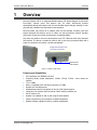
WiMAX
Outdoor CPE
User Manual
Doc No:
OCPE_UM_V1
L
Preface Material
Outdoor CPE User Manual
About this Guide
This User Manual describes the installation procedure for the Outdoor CPE.
Notice
This document contains proprietary and confidential material of Runcom Ltd. Any unauthorized reproduction, use or
disclosure of this material, or any part thereof, is strictly prohibited. This document is solely for the use of Runcom
Ltd. employees and authorized Runcom Ltd. customers.
The material furnished in this document is believed to be accurate and reliable. However, no responsibility is
assumed by Runcom Ltd. for the use of this material. Runcom Ltd. reserves the right to make changes to the
material at any time and without notice.
All other trademarks are the property of their respective owners. Other company and brand products and service
names are trademarks or registered trademarks of their respective holders.
Safety Precautions
To avoid injury and to prevent equipment damage, observe the safety precautions below.
II
•
Outdoor installation procedures should be performed by quality professionals following
all safety and the other requirements and acting in accordance with standard practices
and procedures. Failure to meet safety requirements and/or non-standard practices and
procedures could result in personal injury and/or damage to equipment.
•
Always observe standard safety precautions during installation, operation and
maintenance of this product.
•
This equipment must be installed according to country national electrical codes.
•
Any changes and modifications to the device and the accessories must be approved by
Runcom.
•
All equipment and accessories must be installed in a restricted access area.
•
Observe all the labels on the equipment, providing operation details and warnings.
•
Read and follow the installation instructions provided in this manual.
•
In case of using cables that are not provided with the equipment package, ensure these
cables comply with the regulatory inspection authorities and are the responsibility of the
customer.
•
Do not move or ship equipment unless it is properly packed in its original wrapping and
shipping containers.
Runcom Technologies Ltd.
Outdoor CPE User Manual
Preface Material
Electrical Shock Prevention
•
When connecting equipment to the AC and DC voltage supplies, ensure proper polarity.
•
Disconnect the power source before installing or maintaining the power wiring.
•
Do not operate the equipment if there is any failure or damage to electrical
components.
•
Do not touch exposed connections, components or wiring when power is on.
•
Install the equipment and the grounded DC supply circuits in adjacent cabinets.
•
Protect the DC power source with an adjacent circuit breaker.
•
The equipment must be properly grounded before attempting to operate or perform any
repairs.
RF Exposure
To avoid RF exposure - Installation of antennas must comply with the FCC RF exposure
requirements.
Radio Interference
This equipment generates and radiates radio frequency energy and if not installed and used
in accordance with the instruction manual, may cause interference to radio communications.
To avoid interferences:
•
Avoid conjunction with any other antenna or transmitter.
•
In case of Radio Interference: Relocate the antenna and Increase separation between
the equipment and the receiver (e.g. connect to a separate circuit or outlet).
Runcom Technologies Ltd.
III
Outdoor CPE User Manual
Table of Contents
Table of Contents
1
Overview ...............................................................................................................................1
2
Installing the Outdoor CPE .................................................................................................2
2.1 Site Requirements ..................................................................................................................... 2
2.2 Overview of the Installation Procedure........................................................................................ 3
2.3 Contents of the Outdoor CPE Package......................................................................................... 4
2.4 Mounting the Outdoor CPE......................................................................................................... 4
2.4.1 Mounting Bracket Description............................................................................................ 5
2.4.2 Mounting On a Pole.......................................................................................................... 7
2.4.3 Mounting On a Wall ......................................................................................................... 9
2.5 Connecting Ethernet to the CPE................................................................................................ 11
2.6 Connecting the Lightening Protector and PoE Converter ............................................................. 12
2.7 Adjust the CPE Direction for best Reception............................................................................... 13
3
Setting up the CPE.............................................................................................................14
3.1 Opening a CPE Session ............................................................................................................ 14
3.2 Navigating the Web Based Manager.......................................................................................... 15
3.3 Configuring CPE RF Parameters ................................................................................................ 16
3.3.1 Define BS Scanning Frequencies...................................................................................... 16
3.3.2 Defining Bandwidth........................................................................................................ 17
3.4 Configuring the User Network Parameters ................................................................................. 18
3.4.1 Define the Operation Mode and IP Parameters ................................................................. 18
3.4.2 DHCP Server Configuration ............................................................................................. 19
4
Troubleshooting Connectivity ..........................................................................................21
4.1 General Information ................................................................................................................ 21
4.2 Monitoring Link Information ..................................................................................................... 22
4.2.1 Basic WAN and LAN Link Information............................................................................... 22
4.2.2 Detailed WAN Information .............................................................................................. 23
5
Software Upgrade ..............................................................................................................26
5.1 Software Upgrade (Maintenance Screens) ................................................................................. 26
5.1.1 Upgrade........................................................................................................................ 26
5.1.2 Recovery....................................................................................................................... 27
Runcom Technologies Ltd.
V
Table of Contents
6
Mini NOC User Manual
Appendices......................................................................................................................... 28
6.1 Instructions for Connecting the Weatherproof Connector............................................................ 28
6.2 Outdoor CPE Specifications ...................................................................................................... 31
VI
Runcom Technologies Ltd.
Outdoor CPE User Manual
1
Overview
Overview
Runcom's Outdoor CPE is an integrated WiMAX outdoor CPE device designed for enhanced
line-of-sight, transmit power and antenna gain. Its smart, self-learning antenna
automatically detects base stations with the best available signal strength, allowing for true
plug-and-play installation and maintenance-free operation.
Runcom outdoor CPE consists of an outdoor radio unit that includes a modem, radio and
integral high-gain flat antenna, and of an indoor unit that provides the network interface
(and power), where the network interface type is model dependent.
The indoor and outdoor units are interconnected via a CAT-5 Ethernet cable using standard
PoE interface. The device is installed on either a wall or pole using the same bracket and is
simple to commission and monitor via Web management.
Integrated antenna and
one (PoE) connector
Ethernet and
PoE interface
Figure 1. Outdoor CPE Views
Features and Capabilities
•
•
•
•
•
•
•
•
•
•
•
Full compliance with IEEE802.16e-2005
Frequency Bands (model dependent): 2.3GHz, 2.5GHz, 3.5GHz - other bands are
optional
Tx 2 x 23dBm
Built-in, integrated smart self learning antenna: 2x 7dBm
Outdoor Non-LOS deployment
Standard based security and Quality of Service (QoS) classes support
Comprises of an outdoor radio unit and an indoor network interface unit
PoE to outdoor unit
Outdoor unit installed on wall or pole using the same bracket
Simple commissioning and procedure via Web management
Remote software upgrade monitoring via Web management
Runcom Technologies Ltd.
1
Installing the Outdoor CPE
Outdoor CPE User Manual
2
Installing the Outdoor CPE
2.1
Site Requirements
This section describes the criteria that should be considered when selecting the Outdoor
CPE installation location. The CPE can be mounted on either a pole or a wall.
To choose CPE Installation location
2
•
Best possible location relative to BS
•
Verify that the pole/wall location corresponds to the site plan and takes into account
local regulations and maintenance access.
•
The unit should be mounted in the highest possible point. Reception will increase
according to the height of the antennas.
•
The diameter of the pole on which the base station and antenna are to be mounted is
either:
•
1.00-1.75” or
•
1.75-3.00”
•
Verify that the pole is properly grounded.
•
Verify that there is safe access to the pole, free of any obstacles or other danger for
installers of the PicoPlus BS.
•
Verify that there are no power lines near the pole.
Runcom Technologies Ltd.
Outdoor CPE User Manual
2.2
Installing the Outdoor CPE
Overview of the Installation Procedure
The installation procedure consists of the following steps
1. Verify package contents.
2. Mount the CPE on a pole or a wall (same bracket).
3. Install the Lightening Protection unit on the roof and a PoE Adapter unit indoors.
4. Connect the Ethernet cables between the units and the CPE.
5. Commission the CPE via Web management (Chapter-3).
The following figure shows the final installation – after commissioning.
Figure 2. Installation Overview
Runcom Technologies Ltd.
3
Installing the Outdoor CPE
2.3
Outdoor CPE User Manual
Contents of the Outdoor CPE Package
The Outdoor CPE package includes the following:
2.4
•
WiMAX Outdoor CPE
•
PoE Adapter
•
Lightening protector unit
•
Weather proof connector Shielded RJ45 Plug Kit with Bayonet Locking Type: 17-10001
(Conec)
•
Ethernet cable (depending on ordered model)
•
This User Guide
•
Installation CD that contains documentation.
Mounting the Outdoor CPE
The Outdoor CPE is provided with a mounting kit which includes all the mounting elements
(e.g. mounting-bracket, torques, screws etc.). The CPE can be mounted either on a pole or
on a wall.
This section provides information on:
•
Assembling the mounting bracket
•
Wall mounting
•
Pole mounting
NOTE: The same mounting bracket is used for the wall and the pole installation.
4
Runcom Technologies Ltd.
Outdoor CPE User Manual
2.4.1
Installing the Outdoor CPE
Mounting Bracket Description
The figure below shows the CPE mounting bracket.
NOTE: The same mounting bracket is used for the wall and the pole installation.
BASE
ARM
WALL/POLE
RACKET
CLAMPING
BRACKET
Use for securing
bracket to pole
Figure 3. Overview of the Bracket
Runcom Technologies Ltd.
5
Installing the Outdoor CPE
Outdoor CPE User Manual
The Bracket elements are described in the following table.
Element
Description
BRACKET BASE.
This part is connected to the CPE.
BRACKET ARM.
This part provides the tilt ability, and connects between the
Bracket BASE and MAIN SUPPORT.
WALL/POLE BRACKET
Used for connecting the bracket to the wall.
CLAMPING BRACKET
Used for securing the bracket to the pole.
Provided screws, nuts and washers:
A C
F
A. 4x flat washer M5
E
B
G
B. 4x nut M5
C. 4x spring washer M5 (seems as flat washers)
D
H
D. 4x bolt M8x50
E. 4x washer spring M8
F. 4x washer flat M8
G. 2x nut M8
H. 2x bolt M8x70
I.
6
4x bolt M5x16 - missing
Runcom Technologies Ltd.
Outdoor CPE User Manual
2.4.2
Installing the Outdoor CPE
Mounting On a Pole
Note: When installing on a pole, leave at least 40cm space between the CPE and the top of
the pole for lightning protection.
To install the CPE on a pole
1. Secure the Bracket Base to the CPE underside:
•
Secure the Bracket Base to the underside of the CPE, using the provided screws,
as shown below:
BASE
Secure to CPE
Underside
•
Verify that the orientation of the hole in the BASE is aligned with the elevation axis.
•
Use a tightening torque of 5.7N/m to tighten.
Runcom Technologies Ltd.
7
Installing the Outdoor CPE
Outdoor CPE User Manual
2. Assemble the bracket elements:
•
Secure the WALL/POLE BRACKET to the Bracket Arm and then to the Bracket
Base using the provided screws, as shown below:
BASE - connect
to CPE
WALL/POLE BRACKET
Ridges to
ridges
ARM
Washers and bolt
Note: The bolt head should be positioned in the socket on the Bracket BASE.
•
Use a tightening torque of 24 N/m to tighten.
3. Mount the CPE on the pole, where the procedure varies slightly according to the pole
diameter:
For poles with a diameter of 1.75-3.00”:
POLE SUPPORT
Assembled CONVEX on the pole
8
•
Mount the CPE on the pole using the bracket Pole Support as shown above.
Assemble the bracket CONVEX as shown.
•
Tighten the bracket using the provided screws, according to the pole diameter.
•
Use a tightening torque of 14N/m to tighten.
Runcom Technologies Ltd.
Outdoor CPE User Manual
Installing the Outdoor CPE
For poles with a diameter of 1.00-1.75”:
CLAMPING BRACKET
Assembled CONCAVE
on the pole
2.4.3
•
Mount the CPE on the pole using the Clamping Bracket as shown above.
Assemble the bracket CONCAVE as shown.
•
Tighten the bracket using the provided screws.
•
Use a tightening torque of 14N/m to tighten.
Mounting On a Wall
1. Secure the Bracket Base to the CPE underside:
•
Secure Bracket Base to the underside of the CPE, using the provided screws, as
shown below:
BASE
Secure to CPE
Underside
•
Verify that the orientation of the hole in the BASE is aligned with the elevation axis.
•
Use a tightening torque of 5.7N/m to tighten.
Runcom Technologies Ltd.
9
Installing the Outdoor CPE
Outdoor CPE User Manual
2. Secure the Bracket Arm to the Bracket Base using the provided screws, as shown
below:
BASE
Assemble to
CPE
Ridges to
ridges
i ARM
Washers and bolt
Note: The bolt head should be positioned in the socket on the Bracket BASE.
3. Mount the WALL/POLE BRACKET on the wall in the appropriate position. Note the
azimuth orientation when doing so.
WALL/POLE BRACKET
Secure to a wall
Secure to wall
•
Attach the Bracket Arm to the WALL/POLE BRACKET using the provided
screws.
WALL/POLE BRACKET
ARM
Note:
•
10
The bolt head should be positioned in the ARM socket.
Use a tightening torque of 24 N/m to the azimuth and elevation hardware.
Runcom Technologies Ltd.
Outdoor CPE User Manual
2.5
Installing the Outdoor CPE
Connecting Ethernet to the CPE
Use the weather-proof connector to connect the Ethernet cable to the CPE.
Refer to 6.1 for detailed instructions on wiring and connecting the weatherproof connector.
NOTE: Insert the 8 wires straight in the connectors (NOT crossed).
Weather Proof RJ45 Plug
Figure 4. View of the CPE Weather Proof Ethernet Connector
Runcom Technologies Ltd.
11
Installing the Outdoor CPE
2.6
Outdoor CPE User Manual
Connecting the Lightening Protector and PoE
Converter
NOTE: Detailed instructions are provided with the Lightening Protector and PoE Converter
units.
1. Place the Lightening Protector as close as possible to the entry point to the
building so the cable between the Lightening Protector and the building entry
is as short as possible.
2. Connect the Ethernet cable from the CPE to the Lightening Protector Line Side.
3. Route the Ethernet cable from the Lightening Protector Equipment Side to the PoE
Adapter (located inside the building).
4. Connect the PoE Adapter to the power converter and the converter to the AC power.
5. Connect an Ethernet cable from the PoE Adapter to the computer on which the webbased Manager application is installed.
CAT5 for
Outdoors
Lightening Protector
Line Side
Outdoors
Equipment Side
CAT5 for outdoors
AC Power
Indoors
PoE Converter
ETH cross-cable
Computer with any webbrowser for commissioning
Figure 5. Overview of the Lightening Protector and PoE Converter Connections
12
Runcom Technologies Ltd.
Outdoor CPE User Manual
2.7
Installing the Outdoor CPE
Adjust the CPE Direction for best Reception
This section briefly describes how to view the CPE reception for the purpose of adjusting the
CPE direction. The procedure is performed by opening a web session to the CPE.
Note: The following chapters provide more information on the Web management application
configuration, monitoring and software upgrade capabilities.
To adjust the CPE direction for best reception
1. Connect the computer to the PoE converter Ethernet port.
2. On the computer, run a standard Web browser and enter in the well-known IP address:
196.168.0.10. The Login screen opens:
3. Enter: Username: `admin'; Password: `admin` The Web application screen opens.
4. In Web-based Manager, click the General Information tab.
Numeric reception value
(20-30 db indicates
excellent reception)
5. Observe the Signal Strength field, and tilt the CPE to get the best signal indication.
The physical installation is complete. The user can set up the CPE.
Runcom Technologies Ltd.
13
Setting up the CPE
3
Outdoor CPE User Manual
Setting up the CPE
After the unit is mounted, the user is required to open a Web session to the CPE and set up
the following parameters:
3.1
•
RF parameters – required only if the user is instructed to do so by the operator and
according to the parameters given by the operator.
•
Network parameters – according to the user's network.
Opening a CPE Session
NOTE: The CPE can always be accessed locally using this address – even after its IP address
has been set.. The Login screen opens:
To open a Web session to the CPE
1. Connect the computer to the PoE converter Ethernet port.
2. On the computer, run a standard Web browser and enter in the well-known IP address:
196.168.0.10. The CPE login screen appears.
3. Enter: Username: `admin'; Password: `admin` The Web application screen opens.
14
Runcom Technologies Ltd.
Outdoor CPE User Manual
3.2
Setting up the CPE
Navigating the Web Based Manager
The CPE Web-based management tool supports the following main menus grouping:
•
General Information – displays information on device version, configuration mode, IP
address setting and connection status.
•
Monitoring – parameter monitoring options
•
Configuration – IP settings, operation mode and RF settings
•
Maintenance – software upgrade and restore options
Sub-Menu Options
Menu
Options
Sub –menu
display
Operation
Buttons
Note the following:
•
The Main menu options are on the left, and the relevant sub-menus appear with each
selection.
•
The following Operation Buttons are available in all menus:
•
Reset – reset connection. If the operation requires resetting the system, a reset
confirmation window is displayed.
•
Connect – manually connect the application to the CPE
•
Disconnect – manually disconnect the application from CPE
•
Click the Apply button to implement changes per page.
•
You may perform all the changes (clicking Apply per page), and then reset the system
only once (after completion of all required changes). This does not include switching
between router/bridge modes, as this affects the screens’ appearance.
Runcom Technologies Ltd.
15
Setting up the CPE
3.3
Outdoor CPE User Manual
Configuring CPE RF Parameters
If instructed to, configure the following RF parameters according to the information
provided by your network operator.
3.3.1
•
Scanning frequency range
•
Bandwidth
Define BS Scanning Frequencies
Configure the frequencies to be scanned by the CPE for connection to the BS. The
frequencies can be defined as specific values (if they are known) or as a range of
frequencies.
Note: the RF Scan screen layout changes according to the selected option (Manual/
Automatic scan)
To define the Frequency Search values
1. In Web-based Manager, click the Configuration menu and choose the RF Scan submenu.
Fixed Scan
Screen Layout
Automatic Scan
Screen Layout
2. In the Freq Mode field, choose the method used for defining the Scan-range:
•
Fixed – manually define (in a table) up to 16 fixed frequencies [KHz] to be scanned.
•
Automatic Scan – determine a range of frequencies to be scanned.
3. Click the Apply button to save the updated value. The RF Scan screen layout changes
according to the selected option (Manual/ Automatic scan)
4. For Automatic Scan mode: Set the Start Frequency and the End Frequency.
5. For Manual Scan mode: Enter the Frequencies to be scanned.
6. Click Apply (and Reset if you have completed the required configuration).
16
Runcom Technologies Ltd.
Outdoor CPE User Manual
3.3.2
Setting up the CPE
Defining Bandwidth
To define the system bandwidth
1. In the Web-based Manager, click the Configuration menu and choose the RF Parm
sub-menu.
2. In the Bandwidth field, choose the required bandwidth (values: 5, 10, 7 MHz) and
click Apply.
Note: In the Power Control field – the value should be Auto. Do not modify.
3. Click the Apply button (and Reset if you have completed the required configuration).
Runcom Technologies Ltd.
17
Setting up the CPE
Outdoor CPE User Manual
3.4
Configuring the User Network Parameters
3.4.1
Define the Operation Mode and IP Parameters
This section describes how to configure the CPE according to whether the user's network
includes a single network element (i.e. computer, or a router).
To define the operation mode and IP address parameters
1. In web-based manager, click the Configuration menu and choose the NAT/Bridge
sub-menu.
2. In the NAT Mode field select the mode of operation according to your network
elements:
•
Router mode – the user's network includes a router. If this option is selected,
configure the DHCP parameters according to section 3.4.2.
•
Bridge mode – the user's network consists of a single element a single element (i.e.
computer).
Click the Apply button and then Reset. After setting the system operation mode, the
IP parameters can be configured.
3. Set the LAN IP address- this is the LAN IP address assigned to the CPE (default =
192.168.0.10).
4. Click Apply and then click Reset. The system will re-connect with the updated IP
Parameters.
18
Runcom Technologies Ltd.
Outdoor CPE User Manual
3.4.2
Setting up the CPE
DHCP Server Configuration
This option is relevant if your network includes a router. In that case, the CPE internal DHCP
will allocated addresses according to this configuration.
Note 1: if the DHCP Srv screen will only be available if the NAT mode is set to Router
(see 3.3.1).
Note 2: To use the DHCP server function of the CPE, you must configure all computers on
the LAN as "Obtain an IP Address automatically" mode.
To set the DHCP server parameters
1. In web-based manager, click the Configuration menu and choose the DHCP Server
sub-menu.
2. Verify that DHCP Server is set to Enable - If you disable the Server, you must have
another DHCP server within your network or else you must configure the computer
manually.
3. Define the range of addresses that the DHCP will use to service client requests:
•
Set the DHCP Start address - This field specifies the first of the addresses in the IP
Address pool.
•
Set the DHCP End address - This field specifies the last of the addresses in the IP
Address pool.
4. Define the following:
•
DNS server address - (Optional.) Input the DNS IP address provided by your ISP. Or
consult your ISP.
•
Domain – (Optional.) Input the domain name of your network.
•
DHCP Lease - the amount of time a network user will be allowed connection to the
router with their current DHCP Address. Enter the amount of time, in minutes, that
the user will be "leased" this DHCP Address. The range of the time is 1~2880
minutes. The default value is 120 minutes.
Runcom Technologies Ltd.
19
Setting up the CPE
Outdoor CPE User Manual
5. Click Reset.
20
Runcom Technologies Ltd.
Outdoor CPE User Manual
4
Troubleshooting Connectivity
Troubleshooting Connectivity
Note: You may be asked by the operator's support personnel to refer to these dialogs in
case of troubleshooting or communication problems.
The CPE is monitored through two main menu options:
4.1
•
General Information – single pane summarizing very basic information on the CPE and
link status.
•
Monitoring – two panes providing detailed information on the link to the hosted devices
and to the BS.
General Information
This screen provides basic information on the unit versions, configured IP Address
parameters and link status.
To view the general information data
In web-based manager, click the General Information menu.
The screen contains three parameter
groups:
• General – displays the firmware
version, device MAC address and
security status.
• IP Status – shows operation
mode and IP information defined
in the Configuration menu
option.
• Connection Status – shows
information on the currently
connected BS (BS MAC address,
frequency, etc.), and connection
status and signal strength.
Signal strength is displayed in
bars (RSSI) and CINR in dB,
where 20 to 30 dB is excellent.
Runcom Technologies Ltd.
21
Troubleshooting Connectivity
4.2
Outdoor CPE User Manual
Monitoring Link Information
Two types of link monitoring information are provided:
4.2.1
•
General information on the air link to the base station (WAN) and the link to the user's
network.
•
Detailed information on the UL and DL (e.g. Frequency, ZONE, preamble, traffic
indications, etc.)
Basic WAN and LAN Link Information
The Monitoring - Status screen provides general information (that is valid from the last
unit reset), on the air link to the base station (WAN) and the link to the user's network.
To view the WAN and LAN Status
In web-based manager, click the Monitoring menu and then choose the Status submenu.
Verify the following:
•
Link status is CONNECTED.
•
CPE traffic activity (Sent/Received)
Information on
Air link to BS
Verify that the
status is
CONNECTED
Information on
link to user's
network
CPE traffic
indication
22
Runcom Technologies Ltd.
Outdoor CPE User Manual
4.2.2
Troubleshooting Connectivity
Detailed WAN Information
This section provides detailed information on WAN parameters.
To view the WAN UL and DL information
In web-based manager, click the Monitoring menu and then choose the WAN sub-menu.
The following DL and UL information towards the BS is provided:
DL Information
Field
Description
Frequency
Current BS frequency
Frequency Offset
Accuracy of BS frequency indication (i.e. within 13 Kh).
RSSI
Receive signal strength indicator
Pre CINR
Preamble CINR (Carrier to Interference-plus-Noise Ratio)
Pilot CINR
Pilot CINR
BS ID
BS MAC address
PN/Sec/Cell
Base Station Zone parameters, indicating the relevant permutation
zone in the map (for RF plane configuration).
PN – Pseudo Noise Sequence (in preamble)
Frame Ratio
Runcom Technologies Ltd.
Number of uplink symbols per number of downlink symbols.
23
Troubleshooting Connectivity
Outdoor CPE User Manual
Field
Description
Burst Fec
Burst Forward Error Correction currently in use.
Zone
Zone type supported by the BS. This value is transferred by the BS
towards the CPE.
Link State
Connected / Disconnected
DL Information
24
Tx Power
Transmit power
Head Room
Dynamic Range Margin (available power interval)
Burst Mode
Current modulation scheme
Runcom Technologies Ltd.
Outdoor CPE User Manual
Troubleshooting Connectivity
Runcom Technologies Ltd.
25
Software Upgrade
5
Outdoor CPE User Manual
Software Upgrade
As new or improved features are implemented, you may be required to upgrade the CPE
software in order to take full advantage of these new capabilities.
The software upgrade procedure is performed through the Web management application
Maintenance menu options.
5.1
Software Upgrade (Maintenance Screens)
The maintenance screens are used for upgrading the CPE software, using a file manually
selected (browsed) by the user.
The CPEs are provided with two software banks: Current and Previous, where the user can
revert to the previous software version using the Roll Back button.
5.1.1
Upgrade
This screen is used for upgrading the CPE software.
To upgrade the CPE software
1. In web-based manager, click the Maintenance menu and choose the Upgrade submenu.
2. Click the Browse button and select the relevant software file.
3. Click the Apply button. A message is displayed while the upgrade process is “In
Progress”.
26
Runcom Technologies Ltd.
Outdoor CPE User Manual
5.1.2
Software Upgrade
Recovery
The recovery screen is used for switching between the current and previous software banks
To revert to the previous software bank
1. In web-based manager, click the Maintenance menu and choose the Recovery submenu.
Previous
Firmware
2. Select the Previous Firmware Version row.
3. Click the Roll Back button.
Runcom Technologies Ltd.
27
Appendices
Outdoor CPE User Manual
6
Appendices
6.1
Instructions for Connecting the Weatherproof
Connector
To connect the Weatherproof Connector
1. Strip and prepare the cables for crimping and then insert through the cable fitting and
plug housing assembly. Do not remove insulation of individual conductors.
28
Runcom Technologies Ltd.
Outdoor CPE User Manual
Appendices
2. After inserting the wires into the appropriate positions of the load bar, slide the cable to
a point where the cable jacket hits against the notch of the load bar.
Trim remaining wire ends to approximately 5mm length of the wire tips. Retract the
cable, leaving about 1mm length of the wire tips.
3. Insert the wired load bar into the RJ45 plug
Runcom Technologies Ltd.
29
Appendices
Outdoor CPE User Manual
4. Assemble the RJ45 Housing and turn to secure tightly.
5. Insert the wire load bar into the RJ45 plug all the way until the wire tips are seated
against the inside wall of the plug housing. For shielded version, adjust the drain wires
of the cable to touch the metal shell of the RJ45 plug. Cut out extra drain wire after
termination.
6. Depress the locking tab of RJ45 plug and align it with the wide slot of the plug housing.
Gently pull the cable until the plug is fully seated. Hold the plug in position and rotate
the cable fitting until tightened to a torque of 3.4 Nm (30lb/inch).
30
Runcom Technologies Ltd.
Outdoor CPE User Manual
6.2
Appendices
Outdoor CPE Specifications
The Outdoor CPE installation procedure involves the following accessories:
•
Lightening Protector
•
PoE Transformer unit
•
Mounting kit
This section details the specifications for the Outdoor CPE and accessories.
Radio
Standard Compliance
IEEE802.16e-2005
WiMAX
Fixed
System Capability
LOS, Near LOS, non-LOS
RF bands
2.3 GHz, 2.5 GHz, 3.5 GHz
Channel Bandwidth
3.5 MHz, 5 MHz, 7 MHz, 10 MHz
FFT
2048, 1024, 512
Radio access method
TDD
Modulation
Coding Rates:
Auto select: BPSK, QPSK, 16 QAM, 64 QAM
1/2, 3/4, 5/6 and 2/3
RF Techniques
SISO/MIMO and MRC
Tx power
2 x 23 dBm
Rx sensitivity
-95 dBm
Integrated antennas
2x 7dBi
Polarization: dual-slant ±45 deg
Azimuth and elevation beam width 30deg
LAN
Indoor unit user interface options
10/100-BaseT Ethernet or USB
Networking
Routing, NAT, DHCP client and server
802.1Q/p, ToS/DSCP and L2/L3 address, traffic classification
Management
Network Management
(Over The Air), SNMP V2, standard and proprietary MIBs
System Configuration
SNMP V2, FTP, CLI
Runcom Technologies Ltd.
31
Appendices
Outdoor CPE User Manual
Security
Encryption
AES
Authentication
PKM, PKMv2, EAP-TTLS
Interfaces
Between outdoor and indoor unit
Cat 5 cable with PoE (Standard IEEE 802.3af)
Up to 10 meters
Interface options in the indoor unit
Towards outdoor: PoE
Towards host: 10/100-BaseT Ethernet or integrated RGW with
USB, Ethernet, WiFi and POTS
AC power feed;
18VDC / 1A power supply for the outdoor CPE unit
Physical and Environmental
Dimensions
15cm x 14.5cm x 5cm
Weight
1 Kg / not including mounting kit
Operating external temperature
-40°C - 55°C
Outdoor water-proof casing
IP66 (NEMA 4X)
EMC & EMI: EN 301 489-1, EN 301 489-4, FCC Part 15
Safety: IEC 60950-1, EN 60950-1, UL 60950-1
32
Runcom Technologies Ltd.