1
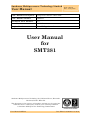
Sundance Multiprocessor Technology Limited
User Manual
Unit / Module Description:
1Gsps dual channel 14bits DAC
Unit / Module Number:
SMT381
Document Issue Number:
1.0
Issue Date:
06/2007
Original Author:
Jean-Philippe Arnaud
Form : QCF42
Date : 6 July 2006
User Manual
for
SMT381
Sundance Multiprocessor Technology Ltd, Chiltern House, Waterside,
Chesham, Bucks. HP5 1PS.
This document is the property of Sundance and may not be copied nor
communicated to a third party without prior written permission.
© Sundance Multiprocessor Technology Limited 2006
User Manual SMT381
Last Edited: 12/06/2007 10:43:00
Revision History
Issue
1.0
Changes Made
New document
User Manual SMT381
Page 2 of 31
Date
Initial
s
06/2007
JPA
Last Edited: 12/06/2007 10:43:00
Table of Contents
1
Introduction ................................................................................................................6
1.1
Module Features .......................................................................................................6
1.2
Possible applications.................................................................................................6
2
Related Documents....................................................................................................7
2.1
Referenced Documents .............................................................................................7
2.2
Applicable Documents ..............................................................................................7
3
Acronyms, Abbreviations and Definitions ...........................................................8
3.1
Acronyms and Abbreviations ...................................................................................8
3.2
Definitions .................................................................................................................8
4
Functional Description.............................................................................................9
4.1
Block Diagram...........................................................................................................9
4.2
Main analogue features ..........................................................................................10
4.3
Clock structure........................................................................................................10
4.4
Analogue output......................................................................................................12
4.5
SLB ..........................................................................................................................14
5
Performance..............................................................................................................14
5.1
6
Waveform Memory..................................................................................................14
Footprint ....................................................................................................................18
6.1
Components location...............................................................................................18
6.2
Test points ...............................................................................................................19
7
Support Packages ....................................................................................................21
7.1
SMT368A.................................................................................................................21
7.1.1 SMT381Control task ..........................................................................................22
7.1.2 Registers_381 task .............................................................................................22
7.1.3 Clock_dac_381v4 task ........................................................................................24
7.1.4 Clock_dac_381v4_div4 task ...............................................................................25
7.1.5 DAC381 task.......................................................................................................25
7.1.6 Sine task .............................................................................................................25
7.1.7 Duplicate task.....................................................................................................25
8
Physical Properties .................................................................................................26
8.1
Mechanical Interface ..............................................................................................26
8.2
Electrical Interface .................................................................................................26
9
Safety ..........................................................................................................................27
10
EMC .............................................................................................................................28
11
Appendix ....................................................................................................................28
User Manual SMT381
Page 3 of 31
Last Edited: 12/06/2007 10:43:00
11.1 Description of the registers ....................................................................................28
11.1.1 The Reset Register (Write Add 0x000)..............................................................28
11.1.2 Temperature Registers (Read Add 0x020, 0x021, 0x028, 0x029) ....................28
11.1.3 DAC Clock Source Registers (Write Add 0x801) ..............................................29
11.1.4 Clock Synthesizer Setup Register (Write Add 0x800)......................................29
11.1.5 PLL Setup Registers (Write Add 0x802 – 0x809) .............................................30
11.1.6 Data Source Selection (Write Add 0x80E) ........................................................30
11.1.7 DAC Setup Registers (Write Add 0x900 – 0x905) ............................................31
User Manual SMT381
Page 4 of 31
Last Edited: 12/06/2007 10:43:00
Table of Figures
Figure 1: block diagram of the SMT381 ................................................................................9
Figure 2: Clock tree of the SMT381 .....................................................................................11
Figure 3. Option 1 for the SMT381 analog output stage. ...................................................12
Figure 4. Option 2 for the SMT381 analog output stage. ...................................................13
Figure 5: Combined analogue output circuit.......................................................................13
Figure 6: Waveform Memory - Time View Capture – 1000Msps (VCO) – 125MHz
analogue output ............................................................................................................14
Figure 7: Measurements of Capture – 1000Msps (VCO) – 125MHz analogue output......15
Figure 8: Waveform Memory - FFT – 1000Msps (VCO) – 125MHz analogue output –
Channel A......................................................................................................................15
Figure 9: Waveform Memory - FFT – 1000Msps (VCO) – 125MHz analogue output –
Channel B......................................................................................................................16
Figure 10: Waveform Memory - FFT – 600Msps (VCO) – 75MHz analogue output –
ChannelA.......................................................................................................................16
Figure 11: Waveform Memory - FFT – 600Msps (VCO) – 75MHz analogue output –
ChannelB.......................................................................................................................17
Figure 12: Connector Location on SMT381.........................................................................18
Figure 13: Test point locations on the SMT381 ..................................................................20
Figure 14: example block diagram.......................................................................................21
Figure 15 Setup Packet Structure .......................................................................................22
Figure 16: Packet Structure – Defined Commands: ...........................................................22
Figure 17: Reset Register (Write Only) ...............................................................................28
Figure 18: Temperature Registers (Read Only) ..................................................................29
Figure 19: Clock Source Selection Table (Write Only) .......................................................29
Figure 20: PLL Setup Registers (Write Only) .....................................................................30
Figure 21: Data Source Selection.........................................................................................31
Figure 22: DAC Setup Registers (Write Only) ....................................................................31
User Manual SMT381
Page 5 of 31
Last Edited: 12/06/2007 10:43:00
1
Introduction
The SMT381 is a single width expansion daughter module capable of converting two
external digital inputs at 1Gsps with a resolution of 14 bits. A Fujitsu dual channel DAC
(MB86064) performs the digital to analogue conversion.
The SMT381 plugs onto a base board which provides an FPGA to interface to the DAC
and control the SMT381. Base board currently available with the SMT381 are
•
SMT338-VP 1 ,
•
SMT368A.
1.1 Module Features
The main features of the SMT381 are listed underneath:
•
Dual channel DAC
•
1 GSPS conversion frequency
•
14 bit data resolution
•
Custom Clock and Trigger inputs via external connectors
•
Internal Waveform generator
•
Standard Sundance comport and SHB interfaces for easy interconnection to
Sundance products via base module.
1.2 Possible applications
The SMT381 can be used for the following applications (this non-exhaustive list should
be taken as an example):
•
Broadband cable modem head-end systems
•
3G Radio transceivers
•
High-data-rate point-to-point radios
•
Medical imaging systems
•
Spectrum analyzers
1 Note that when the SMT381 is coupled with the SMT338-VP, sampling rate of 1Gsps is only achievable when using the
internal memory of the DAC. Limitations in the Virtex2pro architecture limit the frequency to 840Msps with the parallel
interface of the DAC.
User Manual SMT381
Page 6 of 31
Last Edited: 12/06/2007 10:43:00
2
Related Documents
Sundance LVDS Bus (SLB) specifications
Fujitsu MB86064 DAC datasheet
SMT368
SMT338-VP
2.1 Referenced Documents
2.2 Applicable Documents
User Manual SMT381
Last Edited: 12/06/2007 10:43:00
3
Acronyms, Abbreviations and Definitions
3.1 Acronyms and Abbreviations
3.2 Definitions
User Manual SMT381
Last Edited: 12/06/2007 10:43:00
4
Functional Description
4.1 Block Diagram
The following diagram represents the architecture of the SMT381 daughter module.
Figure 1: block diagram of the SMT381
The SMT381 is a daughter board that plugs onto a base board.
The base board sends the digital samples for the DAC and control data for the on-board
clocks and the DAC via the SLB connector.
There are two DAC cores present in the MB86064. Thus two channels are available for
outputs. The outputs of the DAC are differential currents, which are converted to a
voltage by the analogue output stage (RF Transformer).
There are three sources for the sampling clock of the DAC
•
the on-board VCO,
•
the on-board Clock synthesizer,
•
the external clock can be provided as an LVPECL clock or as an RF clock (two
separate inputs).
User Manual SMT381
Last Edited: 12/06/2007 10:43:00
The sampled data can either be supplied to the DAC cores externally via its LVDS data
bus or internally from the Waveform Memory Module. The data may be routed to the
DAC cores through a number of paths. The most direct path routes data straight from
the LVDS input buffers to the DAC core input latches. All digital functions on the
module are controlled by the FPGA of the base board.
4.2 Main analogue features
The main analogue characteristics of the SMT381 are listed in the following table:
Analogue outputs
Output current range
20mA
Data Format
Analogue current
External sampling clock inputs (The clock frequency is divided by 2 on the SMT381 for a DDR clock for
the DAC)
LVPECL Clock
Signal format
LVPECL
Frequency range
25MHz to 1000 MHz
RF Clock
Signal format
Sinus wave
Frequency range
25MHz to 1000 MHz
Amplitude
0dBm Typ
External trigger inputs
Signal format
LVPECL
Frequency range
DC to 100 MHz
DAC performance @ Single tone at -1dBFS, 800MSa/s, DC to 400MHz (From DAC datasheet)
Spurious Free Dynamic Range (SFDR) @ 20MHz
75dBc
Spurious Free Dynamic Range (SFDR) @ 300MHz
58dBc
Cross-talk 4 tone test, each tone at -15dBFS, centred at
276MHz
67dBc
Table 1: main analogue features
4.3 Clock structure
There are two integrated clock generators on the module. The user can either use these
clocks or provide the module with an external clock (input via MMBX connectors). The
following figure shows the SMT381 clock tree.
User Manual SMT381
Page 10 of 31
Last Edited: 12/06/2007 10:43:00
Figure 2: Clock tree of the SMT381
The main clock tree of the SMT381 consists of two clock sources to achieve the DAC’s full
range of input frequencies (DC – 500MHz). The first clock source is a MICREL clock
synthesizer which has a range from 50MHz to 950MHz. This source’s disadvantage
however is that it has a jittery output and thus the clock is not that stable. Its advantage
however is that it can attain a wide range of frequencies, especially the lower
frequencies. The output clock is LVPECL.
The second clock source is a Voltage Controlled Oscillator (VCO) with a phase lock loop.
This combination has a very stable output. However a limited frequency range can be
attained by this combination (300MHz – 600MHz). This is achieved by taking a 600MHz
-1200MHz VCO and dividing the output by 2. The output clock must also be scaled to
LVPECL.
Alternatively the user can provide the module with an external LVPECL clock or an
external RF clock. The user can select between any of these input clocks.
User Manual SMT381
Page 11 of 31
Last Edited: 12/06/2007 10:43:00
The selected clock then drives the DAC and is also distributed to the base board for data
synchronization purposes. On the FPGA of the base board a PLL synchronizes the clock
with the data being sent by using the supplied clock and looping that same clock to the
DAC and back. This technique synchronizes the clock to the data is being sent out on
(base board side) even further with the clock used in the DAC. Synchronization issues
become a bigger factor as the clock frequencies get bigger.
All the clock control is done on the base board in firmware on the FPGA.
4.4 Analogue output
Two options are hardwired into the design. The options are shown below with a figure of
each.
Option 1
Single ended AC coupled output with Macom TP-101 transformer.
TP101
Output
Connector
+
R1
R1
Figure 3. Option 1 for the SMT381 analog output stage.
Option 2
Differential DC coupled output with + and – channels going to separate connectors
User Manual SMT381
Page 12 of 31
Last Edited: 12/06/2007 10:43:00
Output
Connector
+
R2
R2
Output
Connector
Figure 4. Option 2 for the SMT381 analog output stage.
Combined circuit
The two combined:
0 ohm
TP101
+
R3
R3
0 ohm
Figure 5: Combined analogue output circuit
Depending on whether an AC or DC coupled version is ordered the board will be
assembled accordingly to either give the AC or DC coupled circuit shown above.
For more information consult the Fujitsu (MB86064) DAC datasheet.
User Manual SMT381
Page 13 of 31
Last Edited: 12/06/2007 10:43:00
4.5 SLB
The SMT381 connects to a base module (SMT338-VP, SMT398-VP, SMT368) via the SLB
connector. Refer to the SLB specification document for more information.
5
Performance
5.1 Waveform Memory
In the following captures the waveform memory is set up for a cyclic run of 8 samples per
channel and a sinus wave programmed into the memory. One complete cycle of the wave
is loaded into the memory, resulting in a waveform being generated at 1/8th of the
sample frequency. The DAC sample frequency is double that of the clock supplied to the
DAC. So for eg if a 500MHz clock is given to the DAC with the waveform memory
initialized as described above the DAC sample frequency will be 1000MHz and the
generated wave will be 125MHz (1000MHz divided by 8).
Figure 6: Waveform Memory - Time View Capture – 1000Msps (VCO) – 125MHz analogue
output
User Manual SMT381
Page 14 of 31
Last Edited: 12/06/2007 10:43:00
Figure 7: Measurements of Capture – 1000Msps (VCO) – 125MHz analogue output
Figure 8: Waveform Memory - FFT – 1000Msps (VCO) – 125MHz analogue output –
Channel A
User Manual SMT381
Page 15 of 31
Last Edited: 12/06/2007 10:43:00
Figure 9: Waveform Memory - FFT – 1000Msps (VCO) – 125MHz analogue output –
Channel B
Figure 10: Waveform Memory - FFT – 600Msps (VCO) – 75MHz analogue output –
ChannelA
User Manual SMT381
Page 16 of 31
Last Edited: 12/06/2007 10:43:00
Figure 11: Waveform Memory - FFT – 600Msps (VCO) – 75MHz analogue output –
ChannelB
User Manual SMT381
Page 17 of 31
Last Edited: 12/06/2007 10:43:00
6
Footprint
6.1 Components location
The following diagram indicates the location of all the important connectors and
components on the SMT381 (Rev 1) PCB.
Figure 12: Connector Location on SMT381
Diagram
Ref
Pcb
RefDes
Description
Notes
A
J11
External Trigger B Channel
LVPECL Signal. Positive on inside of connector. Negative
on outside of connector.
B
J10
External Trigger A Channel
LVPECL Signal. Positive on inside of connector. Negative
on outside of connector.
C
J13
DAC Output B Channel (neg)
Analog Signal. Signal on inside of connector. GND on
outside of connector. For DC Coupling only (differential
signal, split over both connectors).
D
J3
DAC Output B Channel (pos)
Analog Signal. Signal on inside of connector. GND on
outside of connector. For AC Coupling (single ended), and
pos side of DC coupling (differential)
E
J12
DAC Output A Channel (neg)
Analog Signal. Signal on inside of connector. GND on
outside of connector. For DC Coupling only (differential
signal, split over both connectors).
F
J2
DAC Output A Channel (pos)
Analog Signal. Signal on inside of connector. GND on
outside of connector. For AC Coupling (single ended), and
pos side of DC coupling (differential).
G
J1
DAC Test Clock Output
LVPECL output test clock. Copy of clock going to DAC.
Postive on inside of connector, negative on outside of
User Manual SMT381
Last Edited: 12/06/2007 10:43:00
connector. Used for verification of the clock going to the
DAC.
H
J5
External RF clock input
External Analog input Clock to DAC. Clock on inside of
connector, DGND on the outside of connector.
I
J4
External ECL clock input
External ECL input Clock to DAC. Positive on inside of
connector, negative on the outside of connector.
Table 2: Table of Connector Locations on SMT381
Diagram
Ref
Pcb
RefDes
Description
Notes
J
J8
FPGA
/
Connector
K
U9
Fujitsu DAC
L
TRANS2
M/A
Com
Transformer
TP101
By default the SMT381 analog input is AC coupled
through a twisted pair balum transformer
(differential to single ended). It is possible to change
this configuration to DC coupled by taking out the
transformer and inserting some resistors on the
board.
M
TRANS1
M/A
Com
Transformer
TP101
By default the SMT381 analog input is AC coupled
through a twisted pair balum transformer
(differential to single ended). It is possible to change
this configuration to DC coupled by taking out the
transformer and inserting some resistors on the
board.
N
VCO1
UMC 600 – 1200MHz VCO
O
U31
Clock Synthesizer
950MHz
MSP
JTAG
FPGA / MSP430 on SMT338-VP JTAG Chain. Only
routed down to SMT338-VP. Use for easy access
without having to remove the SMT381.
DAC Requires heat-sink with air-flow cooling in a
system setup.
50
System Clock for the DAC. VCO Requires heat-sink
with air-flow cooling in a system setup.
–
Test Clock for DAC. The range of this clock is wider
than the operating range of the DAC.
Table 3: Table of Component Locations on SMT381
6.2 Test points
The following diagram shows all the Test points present on the board.
User Manual SMT381
Page 19 of 31
Last Edited: 12/06/2007 10:43:00
Figure 13: Test point locations on the SMT381
TP1 – External Clock positive
TP2 – External Clock negative
TP3 – Daughter Card Connector test point
TP4 – Daughter Card Connector test point
TP5 – Daughter Card Connector test point
TP6 – Daughter Card Connector test point
TP7 – 1V8 test point
TP8 – 3V3_IN test point
TP9 – ECL 5V test point
TP10 – 3V3 test point
TP11 – ECL -5V2 test point
TP12 – Analog 3V3
TP13 – VCO 12V
TP14 – VCO 5V
TP15 – VCO Clock positive
TP16 – VCO Clock negative
User Manual SMT381
Page 20 of 31
Last Edited: 12/06/2007 10:43:00
7
Support Packages
The SMT381 can be coupled with several base modules.
provided for each base module.
Example applications are
The examples are developed with 3L Diamond DSP and FPGA design tool.
Source code for the software and firmware tasks is provided. The tasks can be re-used
by users to implement their own applications.
The following sections describe the examples provided for each one of the base boards
available with the SMT381.
7.1 SMT368A
The FPGA uses a Look-Up-Table to generate a sine-wave that is then played out by the
DAC. The sampling frequency and other parameters of the SMT381 are controlled via
software.
The example uses a DSP module to run the software tasks.
SMT368A.
The base module is a
In the example, the FPGA sends the samples for a sine-wave to the DAC. The DSP is
used to configure and control the SMT381 and its base module.
The diagram shows the tasks used in the example and their interconnection.
The task in yellow runs on the DSP of the SMT395; the tasks in blue run on the FPGA of
the base module.
Figure 14: example block diagram
User Manual SMT381
Page 21 of 31
Last Edited: 12/06/2007 10:43:00
The samples generated by task sine are duplicated by task duplicate. Each channel is
sent to task DAC381 which sends the samples to the DAC.
Task registers_381 implements the registers used to control the firmware and the
SMT381 daughter board. Task SMT381Control is a software task which configures the
registers to control the SMT381 and the application. Task clock_dac_381v4 manages
the clocks used to generate the samples in the FPGA and to send them to the DAC.
More details about each task are provided in the following section.
7.1.1 SMT381Control task
This software task allows controlling the SMT381 daughter module.
The task uses a GUI running on the host to select the sampling frequency of the DAC,
the source of the clock and other advanced parameters.
7.1.2 Registers_381 task
This task implements the registers used to control the SMT381 daughter board and the
firmware.
The task has 1 input channel and 2 output channels.
Input 0
Used to read or write the registers.
Output 0
Carries the content of the register that is been read.
Output 1
Carries information used to control the firmware.
7.1.2.1 Protocol
The registers are accessed by writing to input channel 0. The data written to input
channel 0 follow the following protocol to read and write the registers.
31 .. 28
27 .. 24
Command
23 .. 20
19 .. 16
15 .. 12
11 .. 8
Address
7 .. 4
3 .. 0
Data
Figure 15 Setup Packet Structure
The commands are the following:
Command Value
Command Description
0x0
Reserved
0x1
Write the data in the register selected by the address
0x2
Read the data stored in the register selected by the
address. The data is sent on the output channel 0.
Others
Reserved
Figure 16: Packet Structure – Defined Commands:
User Manual SMT381
Page 22 of 31
Last Edited: 12/06/2007 10:43:00
Example 1:
Sending 0x1001FFFF to the task will Write, to Address 0x001, Data FFFF
Example 2:
Sending 0x2801xxxx to the task will request a Read, from Address 0x801. The data will
be written to the output channel 0.
7.1.2.2 Registers addresses
The following figure shows the memory map for registers. Detailed description of the
registers is provided in appendix.
Write Side
Address
Register
Read Side
Address
Register
0x000
Reset Register
0x000
Reserved
0x001
Reserved
0x001
Reserved
0x002
Reserved
0x002
Reserved
0x003
Reserved
0x003
Reserved
0x004
Reserved
0x004
Reserved
0x005
Smt381DacData(LSB)
0x005
Reserved
0x006
Smt381DacData
0x006
Reserved
0x007
Smt381DacData
0x007
Reserved
0x008
Smt381DacData(MSB)
0x008
Reserved
0x009
Smt381DacSetup
0x009
Reserved
0x00A
Smt381DacAddress
0x00A
Reserved
0x00B
Smt381Pll_IfR_Reg1
0x00B
Reserved
0x00C
Smt381Pll_IfR_Reg2
0x00C
Reserved
0x00D
Smt381Pll_IfN_Reg1
0x00D
Reserved
0x00E
Smt381Pll_IfN_Reg2
0x00E
Reserved
0x00F
Smt381Pll_RfR_Reg1
0x00F
Reserved
0x010
Smt381Pll_RfR_Reg2
0x010
Reserved
0x011
Smt381Pll_RfN_Reg1
0x011
Reserved
0x012
Smt381Pll_RfN_Reg2 *
0x012
Reserved
0x013
Smt381AdjClkCntrlReg *
0x013
Reserved
0x014
Smt381ClockSourceSelect
0x014
Reserved
0x015
Reserved
0x015
Reserved
0x016
Reserved
0x016
Reserved
0x017
Reserved
0x017
Reserved
0x018
Reserved
0x018
Reserved
0x019
Reserved
0x019
Reserved
0x01A
Reserved
0x01A
Reserved
0x01B
Reserved
0x01B
Reserved
0x01C
Reserved
0x01C
Reserved
User Manual SMT381
Page 23 of 31
Last Edited: 12/06/2007 10:43:00
0x01D
Reserved
0x01D
Reserved
0x01E
Reserved
0x01E
Reserved
0x01F
Reserved
0x01F
Reserved
0x020
Reserved
0x020
Smt338AirTempReg
0x021
Reserved
0x021
Smt338DiodeTempReg
0x022
Reserved
0x022
Reserved
0x023
Reserved
0x023
Reserved
0x024
Reserved
0x024
Reserved
0x025
Reserved
0x025
Reserved
0x026
Reserved
0x026
Reserved
0x027
Reserved
0x027
Reserved
0x028
Reserved
0x028
DaughterCardAirTempReg
0x029
Reserved
0x029
DaughterCardDiodeTempReg
DAC Module Specific
DAC Module Specific
0x800
Smt381AdjClkCntrlReg *
0x800
Reserved
0x801
Smt381ClockSourceSelect
0x801
Reserved
0x802
Smt381Pll_IfR_Reg1
0x802
Reserved
0x803
Smt381Pll_IfR_Reg2
0x803
Reserved
0x804
Smt381Pll_IfN_Reg1
0x804
Reserved
0x805
Smt381Pll_IfN_Reg2
0x805
Reserved
0x806
Smt381Pll_RfR_Reg1
0x806
Reserved
0x807
Smt381Pll_RfR_Reg2
0x807
Reserved
0x808
Smt381Pll_RfN_Reg1
0x808
Reserved
0x809
Smt381Pll_RfN_Reg2 *
0x809
Reserved
0x80A
Reserved
0x80A
Reserved
0x80B
Reserved
0x80B
Reserved
0x80C
Reserved
0x80C
Reserved
0x80D
Reserved
0x80D
Reserved
0x80E
Data Source Selection
0x80E
Reserved
0x80F
Reserved
0x80F
Reserved
0x900
Smt381SetupData
0x900
Reserved
0x901
Smt381DacAddress
0x901
Reserved
Table 4: registers memory map
7.1.3 Clock_dac_381v4 task
This task generates the clock that is used to send the samples to the DAC.
implements a Delay Locked Loop.
It
The task has 1 input channel and 1 output channel.
User Manual SMT381
Page 24 of 31
Last Edited: 12/06/2007 10:43:00
Input 0
Used to reset the task.
Output 0
Bit 0: the clock used to send data to the DAC.
Bit 1: the clock used to send data to the DAC divided by two.
Bit 2: the clock used to send data to the DAC divided by four.
Bit 3: the clock used to send data to the DAC divided by eight.
Bit 4: the “locked” signal of the DCM used in this task.
The Diamond clock domain generated by this task should be used to clock task
“DAC381”.
7.1.4 Clock_dac_381v4_div4 task
This task generates a Diamond clock domain running at one eighth the sampling
frequency of the DAC. It receives the clock from its input channel which should be
connected to task “clock_dac_381v4”.
7.1.5 DAC381 task
This task interfaces to the DAC. It receives the samples for the DAC on its input
channels and sends them to the LVDS interface of the DAC.
This task interfaces to the two DDR 14-bits LVDS ports of the DAC.
It runs at half the sampling frequency of the DAC.
Input 0
Samples for channel A.
Input 1
Samples for channel B.
Input 2
Bit 0: reset the task when ‘1’.
Input channels 0 and 1 carry two samples at a time on the 32 lower bits of their data
bus.
Bits 15 to 0: first sample
Bits 31 to 16: second sample
7.1.6 Sine task
This task generates the samples of a sine-wave.
7.1.7 Duplicate task
This task duplicates on two output channels the data coming on its input channel.
User Manual SMT381
Page 25 of 31
Last Edited: 12/06/2007 10:43:00
8
Physical Properties
8.1 Mechanical Interface
The depth of the SMT381 combined with a base board is about 21 mm. If the SMT381 is
mated with a PCI carrier two PCI slots will be required for the Module + Carrier
combination. If the SMT381 is mated with a cPCI carrier the Module + Carrier will
require two cPCI slots.
The following table lists the dimensions for the SMT381 and the SMT381 coupled with a
SMT338-VP (SMT381-VP).
Description
Module
SMT381)
Dimensions
Value
(Only
Width: 63.5 mm
Length: 106.68 mm
Height: 21mm (Maximum)
Width: 63.5 mm
Module Dimensions (SMT381-VP)
Length: 106.68 mm
Height: 21mm (Maximum)
SMT381 : 36.71grams
SMT381-VP : 94.30 grams
Weight
SMT381-VP (including fittings)
: 97.40 grams
Table 5: SMT381-VP Dimensions
8.2 Electrical Interface
The following voltages are required by the SMT381 and must be supplied over the
daughter card power connector.
Voltage
Current
Required
D+3V3_IN
2.0 A
D+5V0_IN
500 mA
D+12V0_IN
250 mA
D-12V0_IN
250 mA
DGND
Table 6: SMT381 Power Supply Voltages
User Manual SMT381
Last Edited: 12/06/2007 10:43:00
The following table lists the internal SMT381 voltages that are derived from the voltages
that are provided over the daughter card power connector.
Voltage
Description
D+3V3
Derived from D+3V3_IN
D+1V8
Derived from D+3V3 on SMT381
A+3V3
Derived from D+3V3_IN
VCO+5V0
Derived from D+5V0_IN
VCO+12V0
Derived from D+12V0_IN
ECL-5V2
Derived from D-12V0_IN
AGND
Derived from DGND
Table 7: Internal Power Supply Voltages
9
Safety
This module presents no hazard to the user when in normal use.
User Manual SMT381
Page 27 of 31
Last Edited: 12/06/2007 10:43:00
10 EMC
This module is designed to operate from within an enclosed host system, which is build
to provide EMC shielding. Operation within the EU EMC guidelines is not guaranteed
unless it is installed within an adequate host system.
This module is protected from damage by fast voltage transients originating from outside
the host system which may be introduced through the output cables.
Short circuiting any output to ground does not cause the host PC system to lock up or
reboot.
11 Appendix
11.1 Description of the registers
11.1.1 The Reset Register (Write Add 0x000)
The reset register is used to reset the firmware and some of the components of the
SMT381.
Writing a ‘1’ will put the selected block in the reset state. Writing a ‘0’ will release the
reset.
31 .. 28
27 .. 24
23 .. 20
19 .. 16
15 .. 9
8 .. 0
Command
Address
Data MSB
Data LSB
1
0x000
Reserved
Reset command
Figure 17: Reset Register (Write Only)
Reset command:
Bit 0: firmware reset.
Bit 1: DAC Reset.
11.1.2 Temperature Registers (Read Add 0x020, 0x021,
0x028, 0x029)
There are four temperature registers. Each register is 16 bits long. When the bit value of
the register is converted to a decimal number, that number is the temperature in
degrees Celsius.
Read Request Format:
31 .. 28
27 .. 24
23 .. 20
19 .. 16
15 .. 12
11 .. 8
7 .. 4
3 .. 0
Command
Address
Data MSB
Data LSB
0x2
0x020 (Smt338AirTempReg) (1)
xx
xx
User Manual SMT381
Last Edited: 12/06/2007 10:43:00
0x2
0x021 (Smt338DiodeTempReg) (2)
xx
xx
0x2
0x028 (DaughterCardAirTempReg) (3)
xx
xx
0x2
0x029 (DaughterCardDiodeTempReg) (4)
xx
xx
(1)
- SMT338-VP Air Temperature on Top of PCB
(2)
– SMT338-VP FPGA temperature on Bottom of PCB
(3)
– SMT381 Air Temperature on Bottom of PCB
(4)
– SMT381 ADC temperature on Top of PCB
Read Response Format:
31 .. 28
27 .. 24
23 .. 20
19 .. 16
15 .. 12
11 .. 8
7 .. 4
3 .. 0
Command
Address
Data MSB
Data LSB
0x2
0x020
SMT338-VP
Air Temperature
0x2
0x021
SMT338-VP
Diode Temperature
0x2
0x028
SMT381
Air Temperature
0x2
0x029
SMT381
Diode Temperature
Figure 18: Temperature Registers (Read Only)
11.1.3 DAC Clock Source Registers (Write Add 0x801)
The A and B channels of the DAC can receive a clock from the on-board VCO, the onboard clock synthesizer, or from an external clock (RF or ECL). The following table
shows the different combinations for setting up the SMT381 clock tree.
Register
Value
A Channel Clock Source
B Channel Clock Source
0x0000
On-board VCO
On-board VCO
0x0001
On-board Clock Synthesizer
On-board Clock Synthesizer
0x0002
External ECL Clock
External ECL Clock
0x0003
External ECL Clock
External ECL Clock
0x0004
On-board VCO
On-board VCO
0x0005
On-board Clock Synthesizer
On-board Clock Synthesizer
0x0006
External RF Clock
External RF Clock
0x0007
External RF Clock
External RF Clock
Figure 19: Clock Source Selection Table (Write Only)
11.1.4 Clock Synthesizer Setup Register (Write Add 0x800)
This register sets up the frequency of the clock synthesizer on the SMT381. Any write
operation to this register will trigger the clock synthesizer interface control logic to
initialize the clock synthesizer with its new value.
For a detailed description of the configurable bits in the Clock Synthesizer register
please refer to the “Clock Synthesizer” section under “Firmware Building Blocks” at the
end of this document.
User Manual SMT381
Page 29 of 31
Last Edited: 12/06/2007 10:43:00
11.1.5 PLL Setup Registers (Write Add 0x802 – 0x809)
These registers set up the frequency of the PLL circuit on the SMT381. There are two
sets of registers – one set for setting up the IF side of the PLL, and the other set for
setting up the RF side of the PLL. The IF side is unconnected, while the RF side is
connected to a 600 – 1200 MHz VCO circuit which is divided by two before entering the
DAC at a frequency of 300 – 600MHz. All registers must be initialized, and only when
writing to the final register will both the IF and RF side be configured to their new
values.
31 .. 28
27 .. 24
23 .. 20
19 .. 16
15 .. 12
11 .. 8
Data MSB
7 .. 4
3 .. 0
Command
Address
Data LSB
0x1
0x802
Not Used
Not Used
0x1
0x803
Not Used
Not Used
0x1
0x804
Not Used
Not Used
0x1
0x805
Not Used
Not Used
0x1
0x806
Smt381Pll_RfR_Reg1
Smt381Pll_RfR_Reg1
0x1
0x807
Smt381Pll_RfR_Reg2
Smt381Pll_RfR_Reg2
0x1
0x808
Smt381Pll_RfN_Reg1
Smt381Pll_RfN_Reg1
0x1
0x809
Smt381Pll_RfN_Reg2
Smt381Pll_RfN_Reg2
Figure 20: PLL Setup Registers (Write Only)
For a detailed description of the configurable bits in the PLL registers please refer to the
“PLL Configuration” section under “Firmware Building Blocks” at the end of this
document.
11.1.6 Data Source Selection (Write Add 0x80E)
This register selects between four data sources.
31 .. 28
27 .. 24
23 .. 20
Command
Address
0x1
0x80E
19 .. 16
15 .. 12
11 .. 8
Data MSB
Not Used
7 .. 4
3 .. 0
Data LSB
6..4 : Channel B selection
2..0 : Channel A selection
What follows applies for Channel A and B:
User Manual SMT381
Register
Value
Channel Data Source
0x0
Look Up Table - A Fixed sine period is
stored into a block of ROM as 32 samples.
0x5
SHB to DPRAM – In this mode, 32
samples per channel are loaded via SHB to
be played back continuously and sent to
the DAC.
0x6
SHB to DAC – Samples coming the SHBs
are routed directly to the DAC. A 256-word
(32 bits) FIFO connects the SHB interface
to the DAC.
0x7
RSL to DAC – Samples coming out of the
Page 30 of 31
Last Edited: 12/06/2007 10:43:00
RSL interface are routed to the DAC. This
is the fastest way. A 64-word (64 bits each)
FIFO converts the data into the right
format.
Figure 21: Data Source Selection
When using, the Memory available inside the DAC, any source can be selected. It will
not affect the DAC. It is recommended to keep the selected source into reset.
11.1.7 DAC Setup Registers (Write Add 0x900 – 0x905)
These registers configure the internal functionality of the DAC on the SMT381. There
are six registers – 4 data registers an address register and setup register. The address
and setup registers must be set up before the data registers. Once the data registers are
written to the data, address and setup information contained in all the registers will be
transferred to the DAC over a serial interface.
31 .. 28
27 .. 24
23 .. 20
19 .. 16
15 .. 12
11 .. 8
Data MSB
7 .. 4
3 .. 0
Command
Address
Data LSB
0x1
0x900
Smt381SetupData
Smt381SetupData
0x1
0x901
Smt381DacAddress
Smt381DacAddress
0x1
0x902
Smt381DacData(LSB)
Smt381DacData(LSB)
0x1
0x903
Smt381DacData
Smt381DacData
0x1
0x904
Smt381DacData
Smt381DacData
0x1
0x905
Smt381DacData(MSB)
Smt381DacData(MSB)
Figure 22: DAC Setup Registers (Write Only)
User Manual SMT381
Page 31 of 31
Last Edited: 12/06/2007 10:43:00