1
GE
Security
Visitor CentralTM 1.5.1
User Manual
Copyright
Copyright © 2009, GE Security, Inc. All rights reserved.
This document may not be copied in whole or in part, or otherwise reproduced except as
specifically permitted under US copyright law, without the prior written consent from GE.
Document number/revision: 460603001G (December 2009)
Disclaimer
The information in this document is subject to change without notice. GE, in keeping pace
with technological advances, is a company of product innovation. Therefore, it is difficult to
ensure that all information provided is entirely accurate and up-to-date. GE accepts no
responsibility for inaccuracies or omissions and specifically disclaims any liabilities, losses, or
risks, personal or otherwise, incurred as a consequence, directly or indirectly, of the use or
application of any of the contents of this document.
This publication may contain examples of screen captures and reports used in daily
operations. Examples may include fictitious names of individuals and companies. Any
similarity to names and addresses of actual businesses or persons is entirely coincidental.
Trademarks and patents
Visitor Central product and logo are registered trademarks of GE Security.
GE and the GE monogram are registered trademarks of General Electric.
Other trade names used in this document may be trademarks or registered trademarks of
the manufacturers or vendors of the respective products.
Software license agreement
GE software supplied with GE products is proprietary and furnished under license and can be
used or copied only in accordance with the license terms.
THE ENCLOSED PROGRAM IS FURNISHED SUBJECT TO THE TERMS AND CONDITIONS OF THIS
AGREEMENT. RETENTION OF THE PROGRAM FOR MORE THAN 30 DAYS, OPENING OF THE
SEALED WRAPPER, IF ANY, SURROUNDING THE PROGRAM, OR USE OF THE PROGRAM IN ANY
MANNER IS CONSIDERED ACCEPTANCE OF THE AGREEMENT TERMS. IF THESE TERMS ARE NOT
ACCEPTABLE, RETURN THE UNUSED PROGRAM AND ANY ACCOMPANYING DOCUMENTATION
TO GE FOR A FULL REFUND OF THE LICENSE FEE PAID. (FOR INFORMATION REGARDING THE
RETURN OF PROGRAMS ENCODED OR INCORPORATED WITHIN EQUIPMENT, CONTACT THE
NEAREST GE SALES OFFICE.)
Intended use
Use this product only for the purpose for which it was designed; refer to the data sheet and
user documentation. For the latest product information, contact your GE sales
representative or visit us online at www.gesecurity.com.
FCC compliance
This equipment has been tested and found to comply with the limits for a Class A digital
device, pursuant to part 15 of the FCC Rules. These limits are designed to provide
reasonable protection against harmful interference when the equipment is operated in a
commercial environment. This equipment generates, uses, and can radiate radio frequency
energy and, if not installed and used in accordance with the instruction manual, may cause
harmful interference to radio communications.
You are cautioned that any changes or modifications not expressly approved by the party
responsible for compliance could void the user's authority to operate the equipment.
Contact
Direct all inquiries about GE legal policies with regard to this product to:
Director of Legal Services
GE Security
4575 SW Research Way, Suite 250
Corvallis, OR 97333 USA
Contents
Contents
Preface . . . . . . . . . . . . . . . . . . . . . . . . . . . . . . . . . . . . . . . . . . . . . . . . . . . . . . . . . . . . . . . . . . . . . . . . . . . . . . . . . . . . . . . . ix
Conventions used in this manual . . . . . . . . . . . . . . . . . . . . . . . . . . . . . . . . . . . . . . . . . . . . . . . . . . . . . . . . . . . . . . . . . . ix
Safety terms and symbols . . . . . . . . . . . . . . . . . . . . . . . . . . . . . . . . . . . . . . . . . . . . . . . . . . . . . . . . . . . . . . . . . . . . . . . . ix
Notice about computer viruses . . . . . . . . . . . . . . . . . . . . . . . . . . . . . . . . . . . . . . . . . . . . . . . . . . . . . . . . . . . . . . . . . . . . ix
Following a sequence. . . . . . . . . . . . . . . . . . . . . . . . . . . . . . . . . . . . . . . . . . . . . . . . . . . . . . . . . . . . . . . . . . . . . . . . . . . . . .x
Chapter 1.
Installing Visitor Central . . . . . . . . . . . . . . . . . . . . . . . . . . . . . . . . . . . . . . . . . . . . . . . . . 1
Peripheral hardware configuration matrix . . . . . . . . . . . . . . . . . . . . . . . . . . . . . . . . . . . . . . . . . . . . . . . . . . . . . . . . . 2
System preparation matrix . . . . . . . . . . . . . . . . . . . . . . . . . . . . . . . . . . . . . . . . . . . . . . . . . . . . . . . . . . . . . . . . . . . . . . . 3
Pre-installation checklist . . . . . . . . . . . . . . . . . . . . . . . . . . . . . . . . . . . . . . . . . . . . . . . . . . . . . . . . . . . . . . . . . . . . . . . . . 4
Recommended hardware and software . . . . . . . . . . . . . . . . . . . . . . . . . . . . . . . . . . . . . . . . . . . . . . . . . . . . . . . . . . . . 4
Hardware . . . . . . . . . . . . . . . . . . . . . . . . . . . . . . . . . . . . . . . . . . . . . . . . . . . . . . . . . . . . . . . . . . . . . . . . . . . . . . . . . . . . . . . . .4
Software . . . . . . . . . . . . . . . . . . . . . . . . . . . . . . . . . . . . . . . . . . . . . . . . . . . . . . . . . . . . . . . . . . . . . . . . . . . . . . . . . . . . . . . . . .5
Preparing the operating system . . . . . . . . . . . . . . . . . . . . . . . . . . . . . . . . . . . . . . . . . . . . . . . . . . . . . . . . . . . . . . . . . . 7
Windows Vista. . . . . . . . . . . . . . . . . . . . . . . . . . . . . . . . . . . . . . . . . . . . . . . . . . . . . . . . . . . . . . . . . . . . . . . . . . . . . . . . . . . . .7
Windows firewall . . . . . . . . . . . . . . . . . . . . . . . . . . . . . . . . . . . . . . . . . . . . . . . . . . . . . . . . . . . . . . . . . . . . . . . . . . . . . . . . . .8
Installing Microsoft SQL Server . . . . . . . . . . . . . . . . . . . . . . . . . . . . . . . . . . . . . . . . . . . . . . . . . . . . . . . . . . . . . . . . . . 10
Installing Microsoft SQL Server 2008 . . . . . . . . . . . . . . . . . . . . . . . . . . . . . . . . . . . . . . . . . . . . . . . . . . . . . . . . . . . . . . 10
Installing Microsoft SQL Server 2005 . . . . . . . . . . . . . . . . . . . . . . . . . . . . . . . . . . . . . . . . . . . . . . . . . . . . . . . . . . . . . . 15
Install SQL 2005 Service Pack 2. . . . . . . . . . . . . . . . . . . . . . . . . . . . . . . . . . . . . . . . . . . . . . . . . . . . . . . . . . . . . . . . . . . 20
Setting SQL Server Agent Properties . . . . . . . . . . . . . . . . . . . . . . . . . . . . . . . . . . . . . . . . . . . . . . . . . . . . . . . . . . . . . . 20
Installing Microsoft SQL Server 2000 . . . . . . . . . . . . . . . . . . . . . . . . . . . . . . . . . . . . . . . . . . . . . . . . . . . . . . . . . . . . . . 21
Installing Microsoft SQL Server 2000 Service Pack 4 . . . . . . . . . . . . . . . . . . . . . . . . . . . . . . . . . . . . . . . . . . . . . . . 21
Microsoft SQL Server verification . . . . . . . . . . . . . . . . . . . . . . . . . . . . . . . . . . . . . . . . . . . . . . . . . . . . . . . . . . . . . . . . . 24
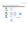
Sample Visitor Central deployment scenario . . . . . . . . . . . . . . . . . . . . . . . . . . . . . . . . . . . . . . . . . . . . . . . . . . . . . . 25
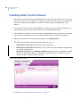
Installing Visitor Central software . . . . . . . . . . . . . . . . . . . . . . . . . . . . . . . . . . . . . . . . . . . . . . . . . . . . . . . . . . . . . . . . 26
Installing Visitor Central server . . . . . . . . . . . . . . . . . . . . . . . . . . . . . . . . . . . . . . . . . . . . . . . . . . . . . . . . . . . . . . . . . . 27
Licensing Visitor Central . . . . . . . . . . . . . . . . . . . . . . . . . . . . . . . . . . . . . . . . . . . . . . . . . . . . . . . . . . . . . . . . . . . . . . . . 30
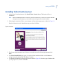
Installing Visitor Central client . . . . . . . . . . . . . . . . . . . . . . . . . . . . . . . . . . . . . . . . . . . . . . . . . . . . . . . . . . . . . . . . . . . 32
Prerequisites . . . . . . . . . . . . . . . . . . . . . . . . . . . . . . . . . . . . . . . . . . . . . . . . . . . . . . . . . . . . . . . . . . . . . . . . . . . . . . . . . . . . 32
To install from the Visitor Central CD. . . . . . . . . . . . . . . . . . . . . . . . . . . . . . . . . . . . . . . . . . . . . . . . . . . . . . . . . . . . . . 32
To install from the Visitor Central Server . . . . . . . . . . . . . . . . . . . . . . . . . . . . . . . . . . . . . . . . . . . . . . . . . . . . . . . . . . 32
When installation begins . . . . . . . . . . . . . . . . . . . . . . . . . . . . . . . . . . . . . . . . . . . . . . . . . . . . . . . . . . . . . . . . . . . . . . . . . 33
What’s next? . . . . . . . . . . . . . . . . . . . . . . . . . . . . . . . . . . . . . . . . . . . . . . . . . . . . . . . . . . . . . . . . . . . . . . . . . . . . . . . . . . . 35
Chapter 2.
Launching and navigating Visitor Central . . . . . . . . . . . . . . . . . . . . . . . . . . . . . . . . 37
Launching the application. . . . . . . . . . . . . . . . . . . . . . . . . . . . . . . . . . . . . . . . . . . . . . . . . . . . . . . . . . . . . . . . . . . . . . . 38
Selecting a Visitor Central module. . . . . . . . . . . . . . . . . . . . . . . . . . . . . . . . . . . . . . . . . . . . . . . . . . . . . . . . . . . . . . . . 39
Starting Visitor Central application . . . . . . . . . . . . . . . . . . . . . . . . . . . . . . . . . . . . . . . . . . . . . . . . . . . . . . . . . . . . . . . 39
Logging on to Visitor Central administrator’s module . . . . . . . . . . . . . . . . . . . . . . . . . . . . . . . . . . . . . . . . . . . . . . 39
Selecting a facility . . . . . . . . . . . . . . . . . . . . . . . . . . . . . . . . . . . . . . . . . . . . . . . . . . . . . . . . . . . . . . . . . . . . . . . . . . . . . . . 39
Navigating the Visitor Central administrator’s module . . . . . . . . . . . . . . . . . . . . . . . . . . . . . . . . . . . . . . . . . . . . . 40
Creating, editing, and deleting records . . . . . . . . . . . . . . . . . . . . . . . . . . . . . . . . . . . . . . . . . . . . . . . . . . . . . . . . . . . 49
Creating records. . . . . . . . . . . . . . . . . . . . . . . . . . . . . . . . . . . . . . . . . . . . . . . . . . . . . . . . . . . . . . . . . . . . . . . . . . . . . . . . . 49
i
ii
Visitor Central 1.5.1
User Manual
Editing records. . . . . . . . . . . . . . . . . . . . . . . . . . . . . . . . . . . . . . . . . . . . . . . . . . . . . . . . . . . . . . . . . . . . . . . . . . . . . . . . . . . 49
Deleting records . . . . . . . . . . . . . . . . . . . . . . . . . . . . . . . . . . . . . . . . . . . . . . . . . . . . . . . . . . . . . . . . . . . . . . . . . . . . . . . . . 50
Configuring kiosk pages . . . . . . . . . . . . . . . . . . . . . . . . . . . . . . . . . . . . . . . . . . . . . . . . . . . . . . . . . . . . . . . . . . . . . . . . 51
What’s next?. . . . . . . . . . . . . . . . . . . . . . . . . . . . . . . . . . . . . . . . . . . . . . . . . . . . . . . . . . . . . . . . . . . . . . . . . . . . . . . . . . . 51
Chapter 3.
Configuring Visitor Central . . . . . . . . . . . . . . . . . . . . . . . . . . . . . . . . . . . . . . . . . . . . . 53
Checklist . . . . . . . . . . . . . . . . . . . . . . . . . . . . . . . . . . . . . . . . . . . . . . . . . . . . . . . . . . . . . . . . . . . . . . . . . . . . . . . . . . . . . . 54
Creating facilities . . . . . . . . . . . . . . . . . . . . . . . . . . . . . . . . . . . . . . . . . . . . . . . . . . . . . . . . . . . . . . . . . . . . . . . . . . . . . . 55
Related procedures . . . . . . . . . . . . . . . . . . . . . . . . . . . . . . . . . . . . . . . . . . . . . . . . . . . . . . . . . . . . . . . . . . . . . . . . . . . . . . 56
Creating visitor types . . . . . . . . . . . . . . . . . . . . . . . . . . . . . . . . . . . . . . . . . . . . . . . . . . . . . . . . . . . . . . . . . . . . . . . . . . . 57
Fields and controls . . . . . . . . . . . . . . . . . . . . . . . . . . . . . . . . . . . . . . . . . . . . . . . . . . . . . . . . . . . . . . . . . . . . . . . . . . . . . . . 57
Related procedures . . . . . . . . . . . . . . . . . . . . . . . . . . . . . . . . . . . . . . . . . . . . . . . . . . . . . . . . . . . . . . . . . . . . . . . . . . . . . . 57
Creating watch lists . . . . . . . . . . . . . . . . . . . . . . . . . . . . . . . . . . . . . . . . . . . . . . . . . . . . . . . . . . . . . . . . . . . . . . . . . . . . 58
Fields and controls . . . . . . . . . . . . . . . . . . . . . . . . . . . . . . . . . . . . . . . . . . . . . . . . . . . . . . . . . . . . . . . . . . . . . . . . . . . . . . . 59
Related procedures . . . . . . . . . . . . . . . . . . . . . . . . . . . . . . . . . . . . . . . . . . . . . . . . . . . . . . . . . . . . . . . . . . . . . . . . . . . . . . 59
Adding a visitor to a watch list. . . . . . . . . . . . . . . . . . . . . . . . . . . . . . . . . . . . . . . . . . . . . . . . . . . . . . . . . . . . . . . . . . . 59
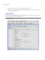
Adding clients. . . . . . . . . . . . . . . . . . . . . . . . . . . . . . . . . . . . . . . . . . . . . . . . . . . . . . . . . . . . . . . . . . . . . . . . . . . . . . . . . . 60
Fields and controls . . . . . . . . . . . . . . . . . . . . . . . . . . . . . . . . . . . . . . . . . . . . . . . . . . . . . . . . . . . . . . . . . . . . . . . . . . . . . . . 61
Related procedures . . . . . . . . . . . . . . . . . . . . . . . . . . . . . . . . . . . . . . . . . . . . . . . . . . . . . . . . . . . . . . . . . . . . . . . . . . . . . . 61
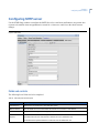
Configuring SMTP server . . . . . . . . . . . . . . . . . . . . . . . . . . . . . . . . . . . . . . . . . . . . . . . . . . . . . . . . . . . . . . . . . . . . . . . . 63
Fields and controls . . . . . . . . . . . . . . . . . . . . . . . . . . . . . . . . . . . . . . . . . . . . . . . . . . . . . . . . . . . . . . . . . . . . . . . . . . . . . . . 63
Related procedures . . . . . . . . . . . . . . . . . . . . . . . . . . . . . . . . . . . . . . . . . . . . . . . . . . . . . . . . . . . . . . . . . . . . . . . . . . . . . . 64
What’s next?. . . . . . . . . . . . . . . . . . . . . . . . . . . . . . . . . . . . . . . . . . . . . . . . . . . . . . . . . . . . . . . . . . . . . . . . . . . . . . . . . . . 64
Chapter 4.
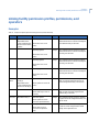
Defining Visitor Central permissions and operators . . . . . . . . . . . . . . . . . . . . . . . 65
Overview . . . . . . . . . . . . . . . . . . . . . . . . . . . . . . . . . . . . . . . . . . . . . . . . . . . . . . . . . . . . . . . . . . . . . . . . . . . . . . . . . . . . . . 66
Creating facility permission profiles. . . . . . . . . . . . . . . . . . . . . . . . . . . . . . . . . . . . . . . . . . . . . . . . . . . . . . . . . . . . . . 68
Example . . . . . . . . . . . . . . . . . . . . . . . . . . . . . . . . . . . . . . . . . . . . . . . . . . . . . . . . . . . . . . . . . . . . . . . . . . . . . . . . . . . . . . . . . 68
Fields and controls . . . . . . . . . . . . . . . . . . . . . . . . . . . . . . . . . . . . . . . . . . . . . . . . . . . . . . . . . . . . . . . . . . . . . . . . . . . . . . . 69
Related procedures . . . . . . . . . . . . . . . . . . . . . . . . . . . . . . . . . . . . . . . . . . . . . . . . . . . . . . . . . . . . . . . . . . . . . . . . . . . . . . 70
Creating system permission profiles . . . . . . . . . . . . . . . . . . . . . . . . . . . . . . . . . . . . . . . . . . . . . . . . . . . . . . . . . . . . . 71
Example . . . . . . . . . . . . . . . . . . . . . . . . . . . . . . . . . . . . . . . . . . . . . . . . . . . . . . . . . . . . . . . . . . . . . . . . . . . . . . . . . . . . . . . . . 71
Fields and controls . . . . . . . . . . . . . . . . . . . . . . . . . . . . . . . . . . . . . . . . . . . . . . . . . . . . . . . . . . . . . . . . . . . . . . . . . . . . . . . 72
Related procedures . . . . . . . . . . . . . . . . . . . . . . . . . . . . . . . . . . . . . . . . . . . . . . . . . . . . . . . . . . . . . . . . . . . . . . . . . . . . . . 74
Configuring permissions . . . . . . . . . . . . . . . . . . . . . . . . . . . . . . . . . . . . . . . . . . . . . . . . . . . . . . . . . . . . . . . . . . . . . . . . 74
Example . . . . . . . . . . . . . . . . . . . . . . . . . . . . . . . . . . . . . . . . . . . . . . . . . . . . . . . . . . . . . . . . . . . . . . . . . . . . . . . . . . . . . . . . . 75
Fields and controls . . . . . . . . . . . . . . . . . . . . . . . . . . . . . . . . . . . . . . . . . . . . . . . . . . . . . . . . . . . . . . . . . . . . . . . . . . . . . . . 75
Related procedures . . . . . . . . . . . . . . . . . . . . . . . . . . . . . . . . . . . . . . . . . . . . . . . . . . . . . . . . . . . . . . . . . . . . . . . . . . . . . . 76
Defining operators . . . . . . . . . . . . . . . . . . . . . . . . . . . . . . . . . . . . . . . . . . . . . . . . . . . . . . . . . . . . . . . . . . . . . . . . . . . . . 76
Example . . . . . . . . . . . . . . . . . . . . . . . . . . . . . . . . . . . . . . . . . . . . . . . . . . . . . . . . . . . . . . . . . . . . . . . . . . . . . . . . . . . . . . . . . 76
Fields and controls . . . . . . . . . . . . . . . . . . . . . . . . . . . . . . . . . . . . . . . . . . . . . . . . . . . . . . . . . . . . . . . . . . . . . . . . . . . . . . . 77
Related procedures . . . . . . . . . . . . . . . . . . . . . . . . . . . . . . . . . . . . . . . . . . . . . . . . . . . . . . . . . . . . . . . . . . . . . . . . . . . . . . 78
Linking facility permission profiles, permissions, and operators. . . . . . . . . . . . . . . . . . . . . . . . . . . . . . . . . . . . . 79
Examples: . . . . . . . . . . . . . . . . . . . . . . . . . . . . . . . . . . . . . . . . . . . . . . . . . . . . . . . . . . . . . . . . . . . . . . . . . . . . . . . . . . . . . . . 79
What’s next?. . . . . . . . . . . . . . . . . . . . . . . . . . . . . . . . . . . . . . . . . . . . . . . . . . . . . . . . . . . . . . . . . . . . . . . . . . . . . . . . . . . 86
Contents
Chapter 5.
Using Express Check-in module . . . . . . . . . . . . . . . . . . . . . . . . . . . . . . . . . . . . . . . . . 87
Overview . . . . . . . . . . . . . . . . . . . . . . . . . . . . . . . . . . . . . . . . . . . . . . . . . . . . . . . . . . . . . . . . . . . . . . . . . . . . . . . . . . . . . . 88
Prerequisites. . . . . . . . . . . . . . . . . . . . . . . . . . . . . . . . . . . . . . . . . . . . . . . . . . . . . . . . . . . . . . . . . . . . . . . . . . . . . . . . . . . 88
Calibrating the scanner. . . . . . . . . . . . . . . . . . . . . . . . . . . . . . . . . . . . . . . . . . . . . . . . . . . . . . . . . . . . . . . . . . . . . . . . . 88
Configuring .xml files . . . . . . . . . . . . . . . . . . . . . . . . . . . . . . . . . . . . . . . . . . . . . . . . . . . . . . . . . . . . . . . . . . . . . . . . . . . 89
Selecting a sample badge layout . . . . . . . . . . . . . . . . . . . . . . . . . . . . . . . . . . . . . . . . . . . . . . . . . . . . . . . . . . . . . . . . . 90
Configuring expressconfig.xml file . . . . . . . . . . . . . . . . . . . . . . . . . . . . . . . . . . . . . . . . . . . . . . . . . . . . . . . . . . . . . . . . 94
Configuring layout .xml files . . . . . . . . . . . . . . . . . . . . . . . . . . . . . . . . . . . . . . . . . . . . . . . . . . . . . . . . . . . . . . . . . . . . . . 94
Sample commented .xml file . . . . . . . . . . . . . . . . . . . . . . . . . . . . . . . . . . . . . . . . . . . . . . . . . . . . . . . . . . . . . . . . . . . . . 96
Configuring .xml values . . . . . . . . . . . . . . . . . . . . . . . . . . . . . . . . . . . . . . . . . . . . . . . . . . . . . . . . . . . . . . . . . . . . . . . . . . 99
.xml badge designs saved from Badge Designer . . . . . . . . . . . . . . . . . . . . . . . . . . . . . . . . . . . . . . . . . . . . . . . . . .104
Implementing bar codes in express badges . . . . . . . . . . . . . . . . . . . . . . . . . . . . . . . . . . . . . . . . . . . . . . . . . . . . . . 105
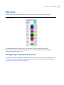
RGB values. . . . . . . . . . . . . . . . . . . . . . . . . . . . . . . . . . . . . . . . . . . . . . . . . . . . . . . . . . . . . . . . . . . . . . . . . . . . . . . . . . . .107
Configuring a displayed document . . . . . . . . . . . . . . . . . . . . . . . . . . . . . . . . . . . . . . . . . . . . . . . . . . . . . . . . . . . . . .107
Checking in . . . . . . . . . . . . . . . . . . . . . . . . . . . . . . . . . . . . . . . . . . . . . . . . . . . . . . . . . . . . . . . . . . . . . . . . . . . . . . . . . . .108
Entering data manually . . . . . . . . . . . . . . . . . . . . . . . . . . . . . . . . . . . . . . . . . . . . . . . . . . . . . . . . . . . . . . . . . . . . . . . . . 108
Using the scanner . . . . . . . . . . . . . . . . . . . . . . . . . . . . . . . . . . . . . . . . . . . . . . . . . . . . . . . . . . . . . . . . . . . . . . . . . . . . . . 109
Banned visitors. . . . . . . . . . . . . . . . . . . . . . . . . . . . . . . . . . . . . . . . . . . . . . . . . . . . . . . . . . . . . . . . . . . . . . . . . . . . . . . .110
Changing the banned reason . . . . . . . . . . . . . . . . . . . . . . . . . . . . . . . . . . . . . . . . . . . . . . . . . . . . . . . . . . . . . . . . . . . 110
Changing the badge status . . . . . . . . . . . . . . . . . . . . . . . . . . . . . . . . . . . . . . . . . . . . . . . . . . . . . . . . . . . . . . . . . . . . .110
Exiting the Express Kiosk module. . . . . . . . . . . . . . . . . . . . . . . . . . . . . . . . . . . . . . . . . . . . . . . . . . . . . . . . . . . . . . . .111
What’s next? . . . . . . . . . . . . . . . . . . . . . . . . . . . . . . . . . . . . . . . . . . . . . . . . . . . . . . . . . . . . . . . . . . . . . . . . . . . . . . . . . .111
Chapter 6.
Using Preregistration module . . . . . . . . . . . . . . . . . . . . . . . . . . . . . . . . . . . . . . . . . . 113
Introduction . . . . . . . . . . . . . . . . . . . . . . . . . . . . . . . . . . . . . . . . . . . . . . . . . . . . . . . . . . . . . . . . . . . . . . . . . . . . . . . . . .114
Appointment checklist . . . . . . . . . . . . . . . . . . . . . . . . . . . . . . . . . . . . . . . . . . . . . . . . . . . . . . . . . . . . . . . . . . . . . . . . .114
Logging on to Preregistration. . . . . . . . . . . . . . . . . . . . . . . . . . . . . . . . . . . . . . . . . . . . . . . . . . . . . . . . . . . . . . . . . . .114
Logging on/off. . . . . . . . . . . . . . . . . . . . . . . . . . . . . . . . . . . . . . . . . . . . . . . . . . . . . . . . . . . . . . . . . . . . . . . . . . . . . . . . . . 114
Fields and controls. . . . . . . . . . . . . . . . . . . . . . . . . . . . . . . . . . . . . . . . . . . . . . . . . . . . . . . . . . . . . . . . . . . . . . . . . . . . . . 116
Update profile. . . . . . . . . . . . . . . . . . . . . . . . . . . . . . . . . . . . . . . . . . . . . . . . . . . . . . . . . . . . . . . . . . . . . . . . . . . . . . . . .117
Related Procedures . . . . . . . . . . . . . . . . . . . . . . . . . . . . . . . . . . . . . . . . . . . . . . . . . . . . . . . . . . . . . . . . . . . . . . . . . . . . . 117
Express status changer . . . . . . . . . . . . . . . . . . . . . . . . . . . . . . . . . . . . . . . . . . . . . . . . . . . . . . . . . . . . . . . . . . . . . . . .118
Related procedures . . . . . . . . . . . . . . . . . . . . . . . . . . . . . . . . . . . . . . . . . . . . . . . . . . . . . . . . . . . . . . . . . . . . . . . . . . . . . 118
Generating an Express report. . . . . . . . . . . . . . . . . . . . . . . . . . . . . . . . . . . . . . . . . . . . . . . . . . . . . . . . . . . . . . . . . . .118
Fields and controls. . . . . . . . . . . . . . . . . . . . . . . . . . . . . . . . . . . . . . . . . . . . . . . . . . . . . . . . . . . . . . . . . . . . . . . . . . . . . . 119
Related procedures . . . . . . . . . . . . . . . . . . . . . . . . . . . . . . . . . . . . . . . . . . . . . . . . . . . . . . . . . . . . . . . . . . . . . . . . . . . . . 119
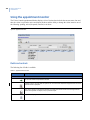
Viewing the appointment list . . . . . . . . . . . . . . . . . . . . . . . . . . . . . . . . . . . . . . . . . . . . . . . . . . . . . . . . . . . . . . . . . . .119
Related procedures . . . . . . . . . . . . . . . . . . . . . . . . . . . . . . . . . . . . . . . . . . . . . . . . . . . . . . . . . . . . . . . . . . . . . . . . . . . . . 120
Creating a new appointment . . . . . . . . . . . . . . . . . . . . . . . . . . . . . . . . . . . . . . . . . . . . . . . . . . . . . . . . . . . . . . . . . . . . 120
Fields and controls. . . . . . . . . . . . . . . . . . . . . . . . . . . . . . . . . . . . . . . . . . . . . . . . . . . . . . . . . . . . . . . . . . . . . . . . . . . . . . 121
Related procedures . . . . . . . . . . . . . . . . . . . . . . . . . . . . . . . . . . . . . . . . . . . . . . . . . . . . . . . . . . . . . . . . . . . . . . . . . . . . . 121
Identifying the host making the appointment . . . . . . . . . . . . . . . . . . . . . . . . . . . . . . . . . . . . . . . . . . . . . . . . . . . .122
Fields and controls. . . . . . . . . . . . . . . . . . . . . . . . . . . . . . . . . . . . . . . . . . . . . . . . . . . . . . . . . . . . . . . . . . . . . . . . . . . . . . 122
Related procedures . . . . . . . . . . . . . . . . . . . . . . . . . . . . . . . . . . . . . . . . . . . . . . . . . . . . . . . . . . . . . . . . . . . . . . . . . . . . . 122
Adding a visitor to an appointment. . . . . . . . . . . . . . . . . . . . . . . . . . . . . . . . . . . . . . . . . . . . . . . . . . . . . . . . . . . . . .124
iii
iv
Visitor Central 1.5.1
User Manual
Existing visitors . . . . . . . . . . . . . . . . . . . . . . . . . . . . . . . . . . . . . . . . . . . . . . . . . . . . . . . . . . . . . . . . . . . . . . . . . . . . . . . . .124
Fields and controls . . . . . . . . . . . . . . . . . . . . . . . . . . . . . . . . . . . . . . . . . . . . . . . . . . . . . . . . . . . . . . . . . . . . . . . . . . . . . .124
Related procedures . . . . . . . . . . . . . . . . . . . . . . . . . . . . . . . . . . . . . . . . . . . . . . . . . . . . . . . . . . . . . . . . . . . . . . . . . . . . .125
Creating a new visitor record . . . . . . . . . . . . . . . . . . . . . . . . . . . . . . . . . . . . . . . . . . . . . . . . . . . . . . . . . . . . . . . . . . . .125
Fields and controls . . . . . . . . . . . . . . . . . . . . . . . . . . . . . . . . . . . . . . . . . . . . . . . . . . . . . . . . . . . . . . . . . . . . . . . . . . . . . .126
Related procedures . . . . . . . . . . . . . . . . . . . . . . . . . . . . . . . . . . . . . . . . . . . . . . . . . . . . . . . . . . . . . . . . . . . . . . . . . . . . .126
What’s next?. . . . . . . . . . . . . . . . . . . . . . . . . . . . . . . . . . . . . . . . . . . . . . . . . . . . . . . . . . . . . . . . . . . . . . . . . . . . . . . . . . 126
Chapter 7.
Using administrator’s module. . . . . . . . . . . . . . . . . . . . . . . . . . . . . . . . . . . . . . . . . . 127
People overview. . . . . . . . . . . . . . . . . . . . . . . . . . . . . . . . . . . . . . . . . . . . . . . . . . . . . . . . . . . . . . . . . . . . . . . . . . . . . . . 128
Defining personnel (people). . . . . . . . . . . . . . . . . . . . . . . . . . . . . . . . . . . . . . . . . . . . . . . . . . . . . . . . . . . . . . . . . . . . . .128
Example . . . . . . . . . . . . . . . . . . . . . . . . . . . . . . . . . . . . . . . . . . . . . . . . . . . . . . . . . . . . . . . . . . . . . . . . . . . . . . . . . . . . . . . .128
Fields and controls . . . . . . . . . . . . . . . . . . . . . . . . . . . . . . . . . . . . . . . . . . . . . . . . . . . . . . . . . . . . . . . . . . . . . . . . . . . . . .129
Related procedures . . . . . . . . . . . . . . . . . . . . . . . . . . . . . . . . . . . . . . . . . . . . . . . . . . . . . . . . . . . . . . . . . . . . . . . . . . . . .131
Defining personnel type . . . . . . . . . . . . . . . . . . . . . . . . . . . . . . . . . . . . . . . . . . . . . . . . . . . . . . . . . . . . . . . . . . . . . . . . .133
Fields and controls . . . . . . . . . . . . . . . . . . . . . . . . . . . . . . . . . . . . . . . . . . . . . . . . . . . . . . . . . . . . . . . . . . . . . . . . . . . . . .134
Related procedures . . . . . . . . . . . . . . . . . . . . . . . . . . . . . . . . . . . . . . . . . . . . . . . . . . . . . . . . . . . . . . . . . . . . . . . . . . . . .134
Defining departments . . . . . . . . . . . . . . . . . . . . . . . . . . . . . . . . . . . . . . . . . . . . . . . . . . . . . . . . . . . . . . . . . . . . . . . . . . .135
Fields and controls . . . . . . . . . . . . . . . . . . . . . . . . . . . . . . . . . . . . . . . . . . . . . . . . . . . . . . . . . . . . . . . . . . . . . . . . . . . . . .136
Related procedures . . . . . . . . . . . . . . . . . . . . . . . . . . . . . . . . . . . . . . . . . . . . . . . . . . . . . . . . . . . . . . . . . . . . . . . . . . . . .136
Defining banned reasons. . . . . . . . . . . . . . . . . . . . . . . . . . . . . . . . . . . . . . . . . . . . . . . . . . . . . . . . . . . . . . . . . . . . . . . .137
Fields and controls . . . . . . . . . . . . . . . . . . . . . . . . . . . . . . . . . . . . . . . . . . . . . . . . . . . . . . . . . . . . . . . . . . . . . . . . . . . . . .137
Related procedures . . . . . . . . . . . . . . . . . . . . . . . . . . . . . . . . . . . . . . . . . . . . . . . . . . . . . . . . . . . . . . . . . . . . . . . . . . . . .138
Changing the banned reason. . . . . . . . . . . . . . . . . . . . . . . . . . . . . . . . . . . . . . . . . . . . . . . . . . . . . . . . . . . . . . . . . . . .138
Managing appointments . . . . . . . . . . . . . . . . . . . . . . . . . . . . . . . . . . . . . . . . . . . . . . . . . . . . . . . . . . . . . . . . . . . . . . . 139
Defining roles . . . . . . . . . . . . . . . . . . . . . . . . . . . . . . . . . . . . . . . . . . . . . . . . . . . . . . . . . . . . . . . . . . . . . . . . . . . . . . . . . . .139
Appointment checklist . . . . . . . . . . . . . . . . . . . . . . . . . . . . . . . . . . . . . . . . . . . . . . . . . . . . . . . . . . . . . . . . . . . . . . . . . 140
Adding visitor contact information . . . . . . . . . . . . . . . . . . . . . . . . . . . . . . . . . . . . . . . . . . . . . . . . . . . . . . . . . . . . . . .141
Fields and controls . . . . . . . . . . . . . . . . . . . . . . . . . . . . . . . . . . . . . . . . . . . . . . . . . . . . . . . . . . . . . . . . . . . . . . . . . . . . . .141
Related procedures . . . . . . . . . . . . . . . . . . . . . . . . . . . . . . . . . . . . . . . . . . . . . . . . . . . . . . . . . . . . . . . . . . . . . . . . . . . . .142
Adding a visitor’s addresses and user fields . . . . . . . . . . . . . . . . . . . . . . . . . . . . . . . . . . . . . . . . . . . . . . . . . . . . . .142
Fields and controls . . . . . . . . . . . . . . . . . . . . . . . . . . . . . . . . . . . . . . . . . . . . . . . . . . . . . . . . . . . . . . . . . . . . . . . . . . . . . .142
Related procedures . . . . . . . . . . . . . . . . . . . . . . . . . . . . . . . . . . . . . . . . . . . . . . . . . . . . . . . . . . . . . . . . . . . . . . . . . . . . .142
Making an appointment . . . . . . . . . . . . . . . . . . . . . . . . . . . . . . . . . . . . . . . . . . . . . . . . . . . . . . . . . . . . . . . . . . . . . . . . .143
Fields and controls . . . . . . . . . . . . . . . . . . . . . . . . . . . . . . . . . . . . . . . . . . . . . . . . . . . . . . . . . . . . . . . . . . . . . . . . . . . . . .144
Scheduling an appointment:. . . . . . . . . . . . . . . . . . . . . . . . . . . . . . . . . . . . . . . . . . . . . . . . . . . . . . . . . . . . . . . . . . . . .144
Assigning visitors to appointments. . . . . . . . . . . . . . . . . . . . . . . . . . . . . . . . . . . . . . . . . . . . . . . . . . . . . . . . . . . . . . .145
Fields and controls . . . . . . . . . . . . . . . . . . . . . . . . . . . . . . . . . . . . . . . . . . . . . . . . . . . . . . . . . . . . . . . . . . . . . . . . . . . . . .145
Using the appointment monitor . . . . . . . . . . . . . . . . . . . . . . . . . . . . . . . . . . . . . . . . . . . . . . . . . . . . . . . . . . . . . . . . 146
Fields and controls . . . . . . . . . . . . . . . . . . . . . . . . . . . . . . . . . . . . . . . . . . . . . . . . . . . . . . . . . . . . . . . . . . . . . . . . . . . . . .146
To check in a visitor from the appointment monitor: . . . . . . . . . . . . . . . . . . . . . . . . . . . . . . . . . . . . . . . . . . . . . .147
To check in a visitor that has an appointment:. . . . . . . . . . . . . . . . . . . . . . . . . . . . . . . . . . . . . . . . . . . . . . . . . . . .149
To create an appointment and check in a visitor: . . . . . . . . . . . . . . . . . . . . . . . . . . . . . . . . . . . . . . . . . . . . . . . . .150
Printing a visitor badge. . . . . . . . . . . . . . . . . . . . . . . . . . . . . . . . . . . . . . . . . . . . . . . . . . . . . . . . . . . . . . . . . . . . . . . . . .151
Fields and controls . . . . . . . . . . . . . . . . . . . . . . . . . . . . . . . . . . . . . . . . . . . . . . . . . . . . . . . . . . . . . . . . . . . . . . . . . . . . .152
Contents
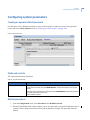
Configuring system parameters . . . . . . . . . . . . . . . . . . . . . . . . . . . . . . . . . . . . . . . . . . . . . . . . . . . . . . . . . . . . . . . .153
Creating an operator default password . . . . . . . . . . . . . . . . . . . . . . . . . . . . . . . . . . . . . . . . . . . . . . . . . . . . . . . . . . 153
Fields and controls. . . . . . . . . . . . . . . . . . . . . . . . . . . . . . . . . . . . . . . . . . . . . . . . . . . . . . . . . . . . . . . . . . . . . . . . . . . . . . 153
Related procedures . . . . . . . . . . . . . . . . . . . . . . . . . . . . . . . . . . . . . . . . . . . . . . . . . . . . . . . . . . . . . . . . . . . . . . . . . . . . . 153
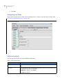
Configuring user fields . . . . . . . . . . . . . . . . . . . . . . . . . . . . . . . . . . . . . . . . . . . . . . . . . . . . . . . . . . . . . . . . . . . . . . . . . . 154
Fields and controls. . . . . . . . . . . . . . . . . . . . . . . . . . . . . . . . . . . . . . . . . . . . . . . . . . . . . . . . . . . . . . . . . . . . . . . . . . . . . . 154
Related procedures . . . . . . . . . . . . . . . . . . . . . . . . . . . . . . . . . . . . . . . . . . . . . . . . . . . . . . . . . . . . . . . . . . . . . . . . . . . . . 155
Mapping scanner configuration fields . . . . . . . . . . . . . . . . . . . . . . . . . . . . . . . . . . . . . . . . . . . . . . . . . . . . . . . . . . . 155
Related procedures . . . . . . . . . . . . . . . . . . . . . . . . . . . . . . . . . . . . . . . . . . . . . . . . . . . . . . . . . . . . . . . . . . . . . . . . . . . . . 156
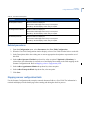
Checking in using the scanner. . . . . . . . . . . . . . . . . . . . . . . . . . . . . . . . . . . . . . . . . . . . . . . . . . . . . . . . . . . . . . . . . . . 157
Watch list visitors . . . . . . . . . . . . . . . . . . . . . . . . . . . . . . . . . . . . . . . . . . . . . . . . . . . . . . . . . . . . . . . . . . . . . . . . . . . . . . . 157
Configuring a Displayed Document. . . . . . . . . . . . . . . . . . . . . . . . . . . . . . . . . . . . . . . . . . . . . . . . . . . . . . . . . . . . . . 158
Fields and controls . . . . . . . . . . . . . . . . . . . . . . . . . . . . . . . . . . . . . . . . . . . . . . . . . . . . . . . . . . . . . . . . . . . . . . . . . . . . . 159
Related procedures . . . . . . . . . . . . . . . . . . . . . . . . . . . . . . . . . . . . . . . . . . . . . . . . . . . . . . . . . . . . . . . . . . . . . . . . . . . . . 159
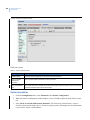
Managing badges . . . . . . . . . . . . . . . . . . . . . . . . . . . . . . . . . . . . . . . . . . . . . . . . . . . . . . . . . . . . . . . . . . . . . . . . . . . . .159
Defining badges . . . . . . . . . . . . . . . . . . . . . . . . . . . . . . . . . . . . . . . . . . . . . . . . . . . . . . . . . . . . . . . . . . . . . . . . . . . . . . . . 159
Fields and controls. . . . . . . . . . . . . . . . . . . . . . . . . . . . . . . . . . . . . . . . . . . . . . . . . . . . . . . . . . . . . . . . . . . . . . . . . . . . . . 160
Related procedures . . . . . . . . . . . . . . . . . . . . . . . . . . . . . . . . . . . . . . . . . . . . . . . . . . . . . . . . . . . . . . . . . . . . . . . . . . . . . 161
Creating badge designs. . . . . . . . . . . . . . . . . . . . . . . . . . . . . . . . . . . . . . . . . . . . . . . . . . . . . . . . . . . . . . . . . . . . . . . . . 162
Example . . . . . . . . . . . . . . . . . . . . . . . . . . . . . . . . . . . . . . . . . . . . . . . . . . . . . . . . . . . . . . . . . . . . . . . . . . . . . . . . . . . . . . . 162
Fields and controls. . . . . . . . . . . . . . . . . . . . . . . . . . . . . . . . . . . . . . . . . . . . . . . . . . . . . . . . . . . . . . . . . . . . . . . . . . . . . . 163
Related procedures . . . . . . . . . . . . . . . . . . . . . . . . . . . . . . . . . . . . . . . . . . . . . . . . . . . . . . . . . . . . . . . . . . . . . . . . . . . . . 164
Badge designer workspace . . . . . . . . . . . . . . . . . . . . . . . . . . . . . . . . . . . . . . . . . . . . . . . . . . . . . . . . . . . . . . . . . . . . . 165
Tool bar . . . . . . . . . . . . . . . . . . . . . . . . . . . . . . . . . . . . . . . . . . . . . . . . . . . . . . . . . . . . . . . . . . . . . . . . . . . . . . . . . . . . . . . . 166
Grid . . . . . . . . . . . . . . . . . . . . . . . . . . . . . . . . . . . . . . . . . . . . . . . . . . . . . . . . . . . . . . . . . . . . . . . . . . . . . . . . . . . . . . . . . . . . 168
Related procedures . . . . . . . . . . . . . . . . . . . . . . . . . . . . . . . . . . . . . . . . . . . . . . . . . . . . . . . . . . . . . . . . . . . . . . . . . . . . . 168
Adding a bar code . . . . . . . . . . . . . . . . . . . . . . . . . . . . . . . . . . . . . . . . . . . . . . . . . . . . . . . . . . . . . . . . . . . . . . . . . . . . . . 170
Drawing a bar code. . . . . . . . . . . . . . . . . . . . . . . . . . . . . . . . . . . . . . . . . . . . . . . . . . . . . . . . . . . . . . . . . . . . . . . . . . . . . 170
Defining custom badge formats . . . . . . . . . . . . . . . . . . . . . . . . . . . . . . . . . . . . . . . . . . . . . . . . . . . . . . . . . . . . . . . . . 171
Fields and controls. . . . . . . . . . . . . . . . . . . . . . . . . . . . . . . . . . . . . . . . . . . . . . . . . . . . . . . . . . . . . . . . . . . . . . . . . . . . . . 171
Related procedures . . . . . . . . . . . . . . . . . . . . . . . . . . . . . . . . . . . . . . . . . . . . . . . . . . . . . . . . . . . . . . . . . . . . . . . . . . . . . 172
Implementing a custom badge format. . . . . . . . . . . . . . . . . . . . . . . . . . . . . . . . . . . . . . . . . . . . . . . . . . . . . . . . . . . 172
Configuring Enterprise Kiosk pages . . . . . . . . . . . . . . . . . . . . . . . . . . . . . . . . . . . . . . . . . . . . . . . . . . . . . . . . . . . . .173
Customizing the Enterprise Kiosk . . . . . . . . . . . . . . . . . . . . . . . . . . . . . . . . . . . . . . . . . . . . . . . . . . . . . . . . . . . . . . . . 174
Fields and controls. . . . . . . . . . . . . . . . . . . . . . . . . . . . . . . . . . . . . . . . . . . . . . . . . . . . . . . . . . . . . . . . . . . . . . . . . . . . . . 174
Related procedures . . . . . . . . . . . . . . . . . . . . . . . . . . . . . . . . . . . . . . . . . . . . . . . . . . . . . . . . . . . . . . . . . . . . . . . . . . . . . 175
Configuring Enterprise Kiosk pages . . . . . . . . . . . . . . . . . . . . . . . . . . . . . . . . . . . . . . . . . . . . . . . . . . . . . . . . . . . . . . 176
Fields and controls. . . . . . . . . . . . . . . . . . . . . . . . . . . . . . . . . . . . . . . . . . . . . . . . . . . . . . . . . . . . . . . . . . . . . . . . . . . . . . 178
Related procedures . . . . . . . . . . . . . . . . . . . . . . . . . . . . . . . . . . . . . . . . . . . . . . . . . . . . . . . . . . . . . . . . . . . . . . . . . . . . . 178
Adding graphic images to pages . . . . . . . . . . . . . . . . . . . . . . . . . . . . . . . . . . . . . . . . . . . . . . . . . . . . . . . . . . . . . . . . 179
Fields and controls. . . . . . . . . . . . . . . . . . . . . . . . . . . . . . . . . . . . . . . . . . . . . . . . . . . . . . . . . . . . . . . . . . . . . . . . . . . . . . 180
Changing page order . . . . . . . . . . . . . . . . . . . . . . . . . . . . . . . . . . . . . . . . . . . . . . . . . . . . . . . . . . . . . . . . . . . . . . . . . . . 181
Fields and controls. . . . . . . . . . . . . . . . . . . . . . . . . . . . . . . . . . . . . . . . . . . . . . . . . . . . . . . . . . . . . . . . . . . . . . . . . . . . . . 181
Configuring default Enterprise Kiosk Check-in . . . . . . . . . . . . . . . . . . . . . . . . . . . . . . . . . . . . . . . . . . . . . . . . . . . . 181
Fields and controls. . . . . . . . . . . . . . . . . . . . . . . . . . . . . . . . . . . . . . . . . . . . . . . . . . . . . . . . . . . . . . . . . . . . . . . . . . . . . . 182
v
vi
Visitor Central 1.5.1
User Manual
Creating database reports . . . . . . . . . . . . . . . . . . . . . . . . . . . . . . . . . . . . . . . . . . . . . . . . . . . . . . . . . . . . . . . . . . . . . 182
Fields and controls . . . . . . . . . . . . . . . . . . . . . . . . . . . . . . . . . . . . . . . . . . . . . . . . . . . . . . . . . . . . . . . . . . . . . . . . . . . . . .182
Creating a report. . . . . . . . . . . . . . . . . . . . . . . . . . . . . . . . . . . . . . . . . . . . . . . . . . . . . . . . . . . . . . . . . . . . . . . . . . . . . . . .184
Viewing a report . . . . . . . . . . . . . . . . . . . . . . . . . . . . . . . . . . . . . . . . . . . . . . . . . . . . . . . . . . . . . . . . . . . . . . . . . . . . . . . .185
SQL variables . . . . . . . . . . . . . . . . . . . . . . . . . . . . . . . . . . . . . . . . . . . . . . . . . . . . . . . . . . . . . . . . . . . . . . . . . . . . . . . . . . .185
SQL keywords . . . . . . . . . . . . . . . . . . . . . . . . . . . . . . . . . . . . . . . . . . . . . . . . . . . . . . . . . . . . . . . . . . . . . . . . . . . . . . . . . .186
Logical operators . . . . . . . . . . . . . . . . . . . . . . . . . . . . . . . . . . . . . . . . . . . . . . . . . . . . . . . . . . . . . . . . . . . . . . . . . . . . . . .188
Relational operators . . . . . . . . . . . . . . . . . . . . . . . . . . . . . . . . . . . . . . . . . . . . . . . . . . . . . . . . . . . . . . . . . . . . . . . . . . . .188
What’s next?. . . . . . . . . . . . . . . . . . . . . . . . . . . . . . . . . . . . . . . . . . . . . . . . . . . . . . . . . . . . . . . . . . . . . . . . . . . . . . . . . . 188
Chapter 8.
Using the Enterprise Kiosk . . . . . . . . . . . . . . . . . . . . . . . . . . . . . . . . . . . . . . . . . . . . . 189
Using a Visitor Central Enterprise Kiosk . . . . . . . . . . . . . . . . . . . . . . . . . . . . . . . . . . . . . . . . . . . . . . . . . . . . . . . . . 190
Prerequisites. . . . . . . . . . . . . . . . . . . . . . . . . . . . . . . . . . . . . . . . . . . . . . . . . . . . . . . . . . . . . . . . . . . . . . . . . . . . . . . . . . . .190
Calibrating the scanner . . . . . . . . . . . . . . . . . . . . . . . . . . . . . . . . . . . . . . . . . . . . . . . . . . . . . . . . . . . . . . . . . . . . . . . . 190
Starting the Visitor Central Enterprise Kiosk . . . . . . . . . . . . . . . . . . . . . . . . . . . . . . . . . . . . . . . . . . . . . . . . . . . . . 191
Checking in . . . . . . . . . . . . . . . . . . . . . . . . . . . . . . . . . . . . . . . . . . . . . . . . . . . . . . . . . . . . . . . . . . . . . . . . . . . . . . . . . . . . .191
Fields and controls . . . . . . . . . . . . . . . . . . . . . . . . . . . . . . . . . . . . . . . . . . . . . . . . . . . . . . . . . . . . . . . . . . . . . . . . . . . . . .192
Related procedures . . . . . . . . . . . . . . . . . . . . . . . . . . . . . . . . . . . . . . . . . . . . . . . . . . . . . . . . . . . . . . . . . . . . . . . . . . . . .192
Changing status of an appointment invitee . . . . . . . . . . . . . . . . . . . . . . . . . . . . . . . . . . . . . . . . . . . . . . . . . . . . . . 193
Exiting Enterprise Kiosk . . . . . . . . . . . . . . . . . . . . . . . . . . . . . . . . . . . . . . . . . . . . . . . . . . . . . . . . . . . . . . . . . . . . . . . . 194
Chapter 9.
Integrating access control . . . . . . . . . . . . . . . . . . . . . . . . . . . . . . . . . . . . . . . . . . . . . 195
Overview . . . . . . . . . . . . . . . . . . . . . . . . . . . . . . . . . . . . . . . . . . . . . . . . . . . . . . . . . . . . . . . . . . . . . . . . . . . . . . . . . . . . . 196
Prerequisites . . . . . . . . . . . . . . . . . . . . . . . . . . . . . . . . . . . . . . . . . . . . . . . . . . . . . . . . . . . . . . . . . . . . . . . . . . . . . . . . . 196
Licensing for access control integration . . . . . . . . . . . . . . . . . . . . . . . . . . . . . . . . . . . . . . . . . . . . . . . . . . . . . . . . . 197
Integrating with Picture Perfect . . . . . . . . . . . . . . . . . . . . . . . . . . . . . . . . . . . . . . . . . . . . . . . . . . . . . . . . . . . . . . . . . .197
Integrating with Secure Perfect . . . . . . . . . . . . . . . . . . . . . . . . . . . . . . . . . . . . . . . . . . . . . . . . . . . . . . . . . . . . . . . . . .197
Integrating with FCWnx . . . . . . . . . . . . . . . . . . . . . . . . . . . . . . . . . . . . . . . . . . . . . . . . . . . . . . . . . . . . . . . . . . . . . . . . .198
Updating the hosts file. . . . . . . . . . . . . . . . . . . . . . . . . . . . . . . . . . . . . . . . . . . . . . . . . . . . . . . . . . . . . . . . . . . . . . . . . 198
Integrating access control and Visitor Central . . . . . . . . . . . . . . . . . . . . . . . . . . . . . . . . . . . . . . . . . . . . . . . . . . . 199
Fields and controls . . . . . . . . . . . . . . . . . . . . . . . . . . . . . . . . . . . . . . . . . . . . . . . . . . . . . . . . . . . . . . . . . . . . . . . . . . . . . .199
Related procedures . . . . . . . . . . . . . . . . . . . . . . . . . . . . . . . . . . . . . . . . . . . . . . . . . . . . . . . . . . . . . . . . . . . . . . . . . . . . .202
Verifying imported data and export configuration . . . . . . . . . . . . . . . . . . . . . . . . . . . . . . . . . . . . . . . . . . . . . . . . 206
Configuring access rights/categories for visitor types . . . . . . . . . . . . . . . . . . . . . . . . . . . . . . . . . . . . . . . . . . . . 207
Used with appointments . . . . . . . . . . . . . . . . . . . . . . . . . . . . . . . . . . . . . . . . . . . . . . . . . . . . . . . . . . . . . . . . . . . . . . . .207
Used with Express Kiosks . . . . . . . . . . . . . . . . . . . . . . . . . . . . . . . . . . . . . . . . . . . . . . . . . . . . . . . . . . . . . . . . . . . . . . . .207
Checking in visitors. . . . . . . . . . . . . . . . . . . . . . . . . . . . . . . . . . . . . . . . . . . . . . . . . . . . . . . . . . . . . . . . . . . . . . . . . . . . 209
Express visitors . . . . . . . . . . . . . . . . . . . . . . . . . . . . . . . . . . . . . . . . . . . . . . . . . . . . . . . . . . . . . . . . . . . . . . . . . . . . . . . . .209
Visitors with prior appointments . . . . . . . . . . . . . . . . . . . . . . . . . . . . . . . . . . . . . . . . . . . . . . . . . . . . . . . . . . . . . . . . .209
Checking out visitors . . . . . . . . . . . . . . . . . . . . . . . . . . . . . . . . . . . . . . . . . . . . . . . . . . . . . . . . . . . . . . . . . . . . . . . . . . 210
Express visitors . . . . . . . . . . . . . . . . . . . . . . . . . . . . . . . . . . . . . . . . . . . . . . . . . . . . . . . . . . . . . . . . . . . . . . . . . . . . . . . . .210
Visitors with prior appointments . . . . . . . . . . . . . . . . . . . . . . . . . . . . . . . . . . . . . . . . . . . . . . . . . . . . . . . . . . . . . . . . .210
Chapter 10. Upgrading Visitor Central. . . . . . . . . . . . . . . . . . . . . . . . . . . . . . . . . . . . . . . . . . . . . . 211
Overview . . . . . . . . . . . . . . . . . . . . . . . . . . . . . . . . . . . . . . . . . . . . . . . . . . . . . . . . . . . . . . . . . . . . . . . . . . . . . . . . . . . . . 212
Server Upgrade . . . . . . . . . . . . . . . . . . . . . . . . . . . . . . . . . . . . . . . . . . . . . . . . . . . . . . . . . . . . . . . . . . . . . . . . . . . . . . . . .212
Contents
Client Upgrade . . . . . . . . . . . . . . . . . . . . . . . . . . . . . . . . . . . . . . . . . . . . . . . . . . . . . . . . . . . . . . . . . . . . . . . . . . . . . . . . . 214
Appendix A. Troubleshooting . . . . . . . . . . . . . . . . . . . . . . . . . . . . . . . . . . . . . . . . . . . . . . . . . . . . . . 217
Visitor Central FAQs . . . . . . . . . . . . . . . . . . . . . . . . . . . . . . . . . . . . . . . . . . . . . . . . . . . . . . . . . . . . . . . . . . . . . . . . . . .218
Identifying SQL port number. . . . . . . . . . . . . . . . . . . . . . . . . . . . . . . . . . . . . . . . . . . . . . . . . . . . . . . . . . . . . . . . . . . .218
Using MSDE Admin utility. . . . . . . . . . . . . . . . . . . . . . . . . . . . . . . . . . . . . . . . . . . . . . . . . . . . . . . . . . . . . . . . . . . . . . .220
Setting debug levels . . . . . . . . . . . . . . . . . . . . . . . . . . . . . . . . . . . . . . . . . . . . . . . . . . . . . . . . . . . . . . . . . . . . . . . . . . .220
Related procedures . . . . . . . . . . . . . . . . . . . . . . . . . . . . . . . . . . . . . . . . . . . . . . . . . . . . . . . . . . . . . . . . . . . . . . . . . . . . . 222
Viewing installation log files for Visitor Central server. . . . . . . . . . . . . . . . . . . . . . . . . . . . . . . . . . . . . . . . . . . . .222
Viewing log file for Visitor Central server. . . . . . . . . . . . . . . . . . . . . . . . . . . . . . . . . . . . . . . . . . . . . . . . . . . . . . . . .222
Viewing Tomcat logs . . . . . . . . . . . . . . . . . . . . . . . . . . . . . . . . . . . . . . . . . . . . . . . . . . . . . . . . . . . . . . . . . . . . . . . . . . .222
Viewing Visitor Central Preregistration log files. . . . . . . . . . . . . . . . . . . . . . . . . . . . . . . . . . . . . . . . . . . . . . . . . . .222
Viewing scanner service log files from event viewer. . . . . . . . . . . . . . . . . . . . . . . . . . . . . . . . . . . . . . . . . . . . . . .223
Application not loading . . . . . . . . . . . . . . . . . . . . . . . . . . . . . . . . . . . . . . . . . . . . . . . . . . . . . . . . . . . . . . . . . . . . . . . .225
Verifying Java plugin version . . . . . . . . . . . . . . . . . . . . . . . . . . . . . . . . . . . . . . . . . . . . . . . . . . . . . . . . . . . . . . . . . . .226
Enabling Java Virtual Machine for my browser . . . . . . . . . . . . . . . . . . . . . . . . . . . . . . . . . . . . . . . . . . . . . . . . . . .226
Verifying JMF installation . . . . . . . . . . . . . . . . . . . . . . . . . . . . . . . . . . . . . . . . . . . . . . . . . . . . . . . . . . . . . . . . . . . . . .226
Testing camera operations . . . . . . . . . . . . . . . . . . . . . . . . . . . . . . . . . . . . . . . . . . . . . . . . . . . . . . . . . . . . . . . . . . . . .227
Changing database passwords . . . . . . . . . . . . . . . . . . . . . . . . . . . . . . . . . . . . . . . . . . . . . . . . . . . . . . . . . . . . . . . . .227
Uninstalling Visitor Central . . . . . . . . . . . . . . . . . . . . . . . . . . . . . . . . . . . . . . . . . . . . . . . . . . . . . . . . . . . . . . . . . . . . .228
Uninstalling Visitor Central Kiosk. . . . . . . . . . . . . . . . . . . . . . . . . . . . . . . . . . . . . . . . . . . . . . . . . . . . . . . . . . . . . . . .229
Backup and restore options . . . . . . . . . . . . . . . . . . . . . . . . . . . . . . . . . . . . . . . . . . . . . . . . . . . . . . . . . . . . . . . . . . . .230
SQL Server 2005 and 2008 Management Studio backup and restore . . . . . . . . . . . . . . . . . . . . . . . . . . . . . . . .230
System recovery checklist . . . . . . . . . . . . . . . . . . . . . . . . . . . . . . . . . . . . . . . . . . . . . . . . . . . . . . . . . . . . . . . . . . . . . . 230
Backing up with SQL Server 2005/2008 Management Studio. . . . . . . . . . . . . . . . . . . . . . . . . . . . . . . . . . . . . . 231
Backing up ‘gevisitorcentral’ database with Microsoft SQL 2005/2008 Management Studio . . . . . . . . 231
Restoring with Microsoft SQL 2005/2008 Management Studio . . . . . . . . . . . . . . . . . . . . . . . . . . . . . . . . . . . . 232
Restoring Visitor Central ‘gevisitorcentral’ database with Management Studio . . . . . . . . . . . . . . . . . . . . . 232
SQL Server 2000 Enterprise Manager backup and restore. . . . . . . . . . . . . . . . . . . . . . . . . . . . . . . . . . . . . . . . . .233
Enterprise system recovery checklist . . . . . . . . . . . . . . . . . . . . . . . . . . . . . . . . . . . . . . . . . . . . . . . . . . . . . . . . . . . . 233
Backing up with SQL Server 2000 Enterprise Manager . . . . . . . . . . . . . . . . . . . . . . . . . . . . . . . . . . . . . . . . . . . . 233
Backing up ‘gevisitorcentral’ database with Enterprise Manager . . . . . . . . . . . . . . . . . . . . . . . . . . . . . . . . . . 234
Restoring with SQL Server 2000 Enterprise Manager . . . . . . . . . . . . . . . . . . . . . . . . . . . . . . . . . . . . . . . . . . . . . 235
Restoring Visitor Central ‘gevisitorcentral’ database with Enterprise Manager . . . . . . . . . . . . . . . . . . . . . 235
Restoring ‘gevisitorcentral’ database from tape with Enterprise Manager . . . . . . . . . . . . . . . . . . . . . . . . . 236
Reclaiming hard drive space . . . . . . . . . . . . . . . . . . . . . . . . . . . . . . . . . . . . . . . . . . . . . . . . . . . . . . . . . . . . . . . . . . . . 236
Other maintenance options with SQL Server 2000 Enterprise Manager . . . . . . . . . . . . . . . . . . . . . . . . . . . . 237
MSDE Admin backup and restore. . . . . . . . . . . . . . . . . . . . . . . . . . . . . . . . . . . . . . . . . . . . . . . . . . . . . . . . . . . . . . . .238
Install MSDE Admin . . . . . . . . . . . . . . . . . . . . . . . . . . . . . . . . . . . . . . . . . . . . . . . . . . . . . . . . . . . . . . . . . . . . . . . . . . . . . 238
Backup with MSDE Admin . . . . . . . . . . . . . . . . . . . . . . . . . . . . . . . . . . . . . . . . . . . . . . . . . . . . . . . . . . . . . . . . . . . . . . . 238
Restore with MSDE Admin. . . . . . . . . . . . . . . . . . . . . . . . . . . . . . . . . . . . . . . . . . . . . . . . . . . . . . . . . . . . . . . . . . . . . . . 239
Contacting technical support . . . . . . . . . . . . . . . . . . . . . . . . . . . . . . . . . . . . . . . . . . . . . . . . . . . . . . . . . . . . . . . . . . .241
Index . . . . . . . . . . . . . . . . . . . . . . . . . . . . . . . . . . . . . . . . . . . . . . . . . . . . . . . . . . . . . . . . . . . . . . . . . . . . . 243
vii
viii
Visitor Central 1.5.1
User Manual
ix
Preface
Visitor Central™ extends all the benefits of an electronic visitor management system, and more. Besides
replacing manually prepared paper-based visitor logs, Visitor Central produces professional, customized photo
visitor badges. Additionally, Visitor Central lets you authorize employees to access the Visitor Central
application and host visitors. Items that display in the application panes are determined by the current user
access privileges.
This document is intended for system administrators who are responsible for the planning and implementation
of the system design, and who perform system configuration and setup using Visitor CentralTM forms that are
accessible only to the master-level operator. Operators using the system should read the chapters that relate to
their duties.
The material in this document has been prepared for persons responsible for, and familiar with the security
needs of the customer facility. Changes since the last publication of this document are marked by a change bar,
which is a vertical line in the margin that visually identifies significant new or revised material.
Conventions used in this manual
The following conventions are used in this manual to make it easier for you to identify important information.
Bold
Menu items and buttons.
Windows, panes, tabs, fields, variables, and other GUI elements.
Italic
Titles of books and various documents.
Emphasis of an instruction or point; special items.
Monospace
Text that displays on the computer screen. File names, path names, or coding sequences.
Blue italic
Hyperlinks to cross-references, related topics, and URL addresses.
Safety terms and symbols
These terms may display in this manual:
Improper use could cause equipment damage or serious personal injury.
I
Improper use may cause equipment damage.
Notice about computer viruses
GE recommends that antivirus protection software be installed and frequently updated on GE Servers and
workstations before connecting them to any network. GE assumes no responsibility for damage caused by
computer viruses, protecting your GE system from viruses, or installing antivirus protection software required
by your IT Department.
Contact your IT Department regarding antivirus software before connecting your system to a network.
x
Visitor Central 1.5.1
User Manual
Following a sequence
We recommend the following sequence for preparation and use of your Visitor Central system:
Table 1.
Recommended preparation and use sequence
1. Complete hardware installation and configuration - “Peripheral hardware configuration
matrix” on page 2
2. Decide Visitor Central system requirements in your facilities - “System preparation matrix”
on page 3
3. Install Visitor Central software - “Pre-installation checklist” on page 4
4. Navigate the Visitor Central system - Chapter 2, Launching and navigating Visitor Central on
page 37
5. Configure facilities, visitor types, and clients - Chapter 3, Configuring Visitor Central on
page 53
6. Define operators (hosts) and permissions - Chapter 4, Defining Visitor Central permissions
and operators on page 65
7. Begin using the Express system for visitors WITHOUT an appointment:
•
•
Chapter 5, Using Express Check-in module on page 87
Chapter 6, Using Preregistration module on page 113
8. Use the Enterprise system administrator’s module to define people, make appointments,
assign visitors, monitor, and manage - Chapter 7, Using administrator’s module on page 127
9. Begin using the Enterprise kiosk for visitors WITH an appointment - Chapter 8, Using the
Enterprise Kiosk on page 189
Chapter 1 Installing Visitor Central
This chapter provides a list of prerequisites for a successful Visitor Central
system, as well as step-by-step instructions for installation. Follow instructions in
the order presented.
In this chapter:
Peripheral hardware configuration matrix. . . . . . . . . . . . . . . . . . . . . . . . 2
System preparation matrix . . . . . . . . . . . . . . . . . . . . . . . . . . . . . . . . . . . . 3
Pre-installation checklist . . . . . . . . . . . . . . . . . . . . . . . . . . . . . . . . . . . . . 4
Recommended hardware and software . . . . . . . . . . . . . . . . . . . . . . . . . . . 4
Preparing the operating system . . . . . . . . . . . . . . . . . . . . . . . . . . . . . . . . 7
Installing Microsoft SQL Server . . . . . . . . . . . . . . . . . . . . . . . . . . . . . . . . 9
Sample Visitor Central deployment scenario . . . . . . . . . . . . . . . . . . . . . 24
Installing Visitor Central software . . . . . . . . . . . . . . . . . . . . . . . . . . . . . 25
Installing Visitor Central server . . . . . . . . . . . . . . . . . . . . . . . . . . . . . . . 26
Licensing Visitor Central . . . . . . . . . . . . . . . . . . . . . . . . . . . . . . . . . . . . 29
Installing Visitor Central client . . . . . . . . . . . . . . . . . . . . . . . . . . . . . . . 31
What’s next? . . . . . . . . . . . . . . . . . . . . . . . . . . . . . . . . . . . . . . . . . . . . . . 34
Visitor Central 1.5.1
User Manual
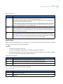
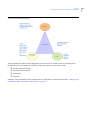
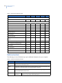
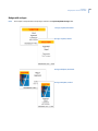
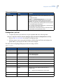
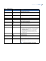
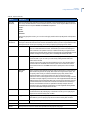
Peripheral hardware configuration matrix
Use this list of considerations when preparing a successfully employed Visitor Central system.
Table 2.
Peripheral hardware installation matrix
Minimum requirements met (refer to Installation Manual
received with device as well as this manual.)
Software installed including necessary Service Packs
Drivers installed
Configuration complete
Calibration required and complete
Product is licensed or registered
Power cables connected and plugged in to power supply
USB cables connected to USB port of computer
Network connection configured (check with your IS Dept.)
Print material (badges) loaded
Ink cartridges loaded
Network cable connected and connection configured
Internet configuration complete
Firewalls disabled during installation
Printer alignment tested
Proximity and Vicinity/Mifare Desktop Credential Reader
installed (if applicable for access control integration)
Other:
Other
Touch screen monitor
Bar code scanner
License/Passport
scanners
Camera
Printer
Visitor Central Peripheral Hardware Configuration Matrix
Computer
2
Chapter 1
Installing Visitor Central
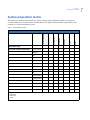
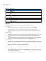
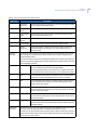
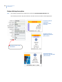
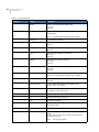
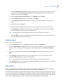
System preparation matrix
This matrix is a sample of requirements in a Visitor Central system configuration. Before you begin, we
recommend that you review this matrix, and then discuss the options and information requirements of your
company in a Visitor management system.
Table 3.
System preparation matrix
Not Escorted
Contractor
Employee
Decide data collection requirements:
First/last name
B
B
B
B
Company
Title
Address
Host
Facility
Department
Employee ID
PIN
Add as operator
Banned Reasons
Create and assign badge designs:
Landscape logo
Portrait logo
Custom 1
Custom 2
Legend:
D = Data only
P = Print only
B = both
Other
Escorted
X
Decide Visitor Types:
Other
COLLECT FROM SCAN
Visitor Central System Preparation Matrix
3
4
Visitor Central 1.5.1
User Manual
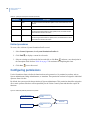
Pre-installation checklist
To prepare your Visitor Central Server computer, refer to this checklist of reminders:
Note:
Before you begin, you must have an Internet Explorer 6.0 with Service Pack 2 or higher connection configured.
S
See your IS Administrator to set network settings appropriate for your Visitor Central configuration.
S
Meet minimum recommended hardware and software requirements. Refer to “Recommended
hardware and software” on page 4.
S
Install the operating system.
S
Install peripheral devices such as printers, cameras, a scanning device, and optional touch-screen
monitor, as supported by GE.
Note:
For faster response, we recommend that the printer be directly connected to your workstation.
Recommended hardware and software
Hardware
The following are recommended minimum hardware requirements for the Server computer:
S
Intel® Pentium® 4 1.5 GHz processor
S
512 MB RAM for Server computers (256 MB RAM for client computers)
S
SVGA Monitor, 1024 by 768 resolution or greater, 16-Bit High Color
S
101 Keyboard
S
Mouse or Trackball device
S
Network card
S
40 GB hard drive space on Servers (20 GB hard drive space on client computers)
S
Up to four available USB 1.1 or USB 2.0 ports
For Visitor Central Web clients, imaging clients, and kiosk:
S
GE supports the following printers, installed according to manufacturer’s instructions:
•
•
Epson C8X series (C88, C86, C84, C82, or C80)
Lexmark Models 510 and 510N
Chapter 1
Installing Visitor Central
S
GE supports the following cameras, installed according to manufacturer’s instructions:
•
•
S
GE supports the following scanners:
•
•
S
Scanshell 800 drivers license scanner
Scanshell 1000 document scanner
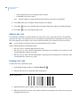
GE supports any scanner-type bar code reader that can read these barcode types:
•
•
•
S
Digi Watchport V and V2 Cameras
Logitech QuickCam
Code 128
Code 2 of 7
Code 3 of 9
OPTIONAL
•
•
•
•
Touch-screen monitor with monitor resolution to a minimum of 1024 by 768 pixels.
Proximity and Vicinity/Mifare Desktop Credential Reader (if applicable for access control
integration)
Topaz Signature Tablet Model T-L462-HSB
Topaz Signature Tablet Model T-LBK766
Hard drive space varies depending on your system environment. If you elect to partition your hard drive, verify
that sufficient space remains in your system drive for your program files to load properly.
Software
The following are recommended minimum software requirements:
S
One of the following for Server computers:
•
•
•
Windows 2003 Server R2 Standard Edition
• Microsoft SQL Server 2005 Standard Edition with Service Pack 2, and a named instance of
VCSQL
Windows XP Professional (SP3 or later) or Windows Vista Business (SP1 or later)
• Microsoft SQL Server 2008 Express with a named instance of VCSQL
Windows Server 2008
• Microsoft SQL Server 2008 with a named instance of VCSQL
5
6
Visitor Central 1.5.1
User Manual
S
One of the following for Server and client computers:
•
•
Windows XP Professional (SP3 or later)
Windows Vista Business (SP1 or later)
S
Internet Explorer 6.0 with Service Pack 2 or higher
S
Device drivers for attached peripherals
The following items are required for imaging kiosks:
S
Java 6 update 13 (installs automatically during Visitor Central installation)
S
JMF imaging component (installs automatically during Visitor Central installation)
S
JMF Diagnostics (installs automatically during Visitor Central installation)
S
These items are required for imaging kiosks. Active links display on the Visitor Central Webtop home
page after logon for your convenience in downloading and installation of the following:
•
•
•
•
•
•
•
*
Java 6 update 13*
JMF imaging component*
Flash Plug-in*
CSSN Driver Licenses and Passports SDK*
.Net Framework*
If your Visitor Central system uses a firewall (such as BlackICE) for network communication, you
may need to disable the firewall or add Visitor Central to the firewall application exceptions list.
Drivers for the Topaz SignatureGem Tablet
Automatically installs during Visitor Central client CD installation
Chapter 1
Installing Visitor Central
Preparing the operating system
Note:
If you purchased this system from GE, the operating system is installed for you.
If your chosen operating system is not already installed on your system, you need to install it now.
1. Insert the Windows Installation disc in your CD/DVD drive and follow the instructions provided by
the Microsoft documentation.
2. This section represents an overview of the installation procedure and does not provide step-by-step
instructions to install the operating system.
During the installation of the operating system, review the following items:
Note:
A Visitor Central Server name cannot contain an underscore (_).
•
•
•
•
•
•
You are asked to select a file system type. For added security, we recommend that you select
NTFS.
In the ‘Networking Settings’ window, we recommend that you select Typical Settings. If you need
to select Custom Settings, please consult your network administrator.
For network services and binding, leave the default settings.
At the ‘Workgroup or computer domain’ window, select one:
• No, this computer is not on a network, or is on a network without a domain. Type a
workgroup name in the following box.
• Yes, make this computer a member of the following domain.
Enter the workgroup or domain name in the ‘Workgroup or computer domain’ field.
By default, the Password Policy is enabled for Windows 2008 Server. You will be asked to change
the Administrator password after installation is complete.
For additional information, consult your Microsoft documentation.
Windows Vista
If you install Visitor Central server on a Windows Vista system, you must disable the User Account Control
(UAC) before installing the Visitor Central application.
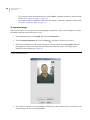
To disable the User Account Control (UAC):
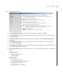
1. Click Start, and then click Control Panel.
Control Panel Home View
2. Click User Accounts and Family Safety, and then click User Accounts.
3. Click Turn User Account Control on or off.
Make sure the Use User Account Control (UAC) to help protect your computer check box is not
checked.
Classic View
4. Double-click User Accounts.
7
8
Visitor Central 1.5.1
User Manual
5. Click Turn User Account Control on or off.
Make sure the Use User Account Control (UAC) to help protect your computer check box is not
checked.
Close all open windows.
6. Reboot your computer for changes to take effect.
Note:
After installation and licensing the Visitor Central application, you can enable User Account Control (UAC) by selecting
the Use User Account Control (UAC) check box.
Windows firewall
Windows Server 2003
Firewall exceptions list
If the Firewall is selected ON, File and Printer Sharing on the Firewall Exceptions list must be enabled. The
SQL database port and port 8080 (HTTP communication) must also be added to the Firewall Exceptions list.
To enable File and Printer Sharing:
1. Click Start and then click Control Panel.
2. On the control panel, double-click Windows Firewall.
3. On the Exceptions tab of the Windows Firewall window, make sure that the File and Printer
Sharing check box is checked, and then click OK.
To add the SQL database port to the Firewall Exceptions list:
1. On the Exceptions tab of the Windows Firewall window, click Add Port.
2. On the Add a Port window, enter the SQL database port number. To obtain the SQL database port
number, refer to Identifying SQL port number on page 218.
3. Select TCP, and then click OK.
To add port 8080 (HTTP communication) to the Firewall Exceptions list:
1. On the Exceptions tab of the Windows Firewall window, click Add Port.
2. On the Add a Port window, enter 8080 in the Port number field.
3. Select TCP, and then click OK.
Windows Server 2008
Firewall exceptions list
If the Firewall is selected ON, the following must be enabled in the Firewall Exceptions list. The SQL database
port and port 8080 (HTTP communication) must also be added to the Firewall Exceptions list.
•
•
•
File and Printer Sharing
Network discovery
Workgroup Only: Remote Administration
Chapter 1
Installing Visitor Central
To enable Firewall Exceptions selections:
1. Click Start and then click Control Panel.
2. On the control panel, double-click Windows Firewall.
3. On the Exceptions tab of the Windows Firewall window, make sure that the following check boxes
are checked, and then click OK.
•
•
•
File and Printer Sharing
Network discovery
Workgroup Only: Remote Administration
To add the SQL database port to the Firewall Exceptions list:
1. On the Exceptions tab of the Windows Firewall window, click Add Port.
2. On the Add a Port window, enter the SQL database port number. To obtain the SQL database port
number, refer to Identifying SQL port number on page 218.
3. Select TCP, and then click OK.
To add port 8080 (HTTP communication) to the Firewall Exceptions list:
1. On the Exceptions tab of the Windows Firewall window, click Add Port.
2. On the Add a Port window, enter 8080 in the Port number field.
3. Select TCP, and then click OK.
9
10
Visitor Central 1.5.1
User Manual
Installing Microsoft SQL Server
Note:
If you purchased this system from GE Security, SQL Server is installed and configured for you.
The SQL Server software is user supplied and is not included as part of a Visitor Central system. The SQL
Server program stores and controls the Visitor Central databases. If you do not have SQL Server installed on
the server computer that will store your databases, you must install it now. The following procedures provide a
standard installation and based on your needs you may choose other available features. There are two versions:
•
•
•
Installing Microsoft SQL Server 2008 on page 10
Installing Microsoft SQL Server 2005 on page 15
Installing Microsoft SQL Server 2000 on page 21
Installing Microsoft SQL Server 2008
To install Microsoft SQL Server 2008:
1. Insert the Microsoft SQL Server 2008 CD or the product DVD into the CD/DVD drive and wait as the
Microsoft SQL Server 2008 page automatically opens.
2. When the AutoPlay page opens, click Run SETUP.EXE.
3. A window displays a list of prerequisites, required prior to installing SQL Server. Click OK to begin
installing the components.
4. When the .NET Framework Welcome to Setup page opens, review the agreement, select I have read
and ACCEPT the terms of the Licence Agreement, and then click Install.
5. When the process is complete, the .NET Installation complete page opens, click Exit.
6. The Windows Update Standalone Installer page opens, click OK to install Windows software
updates.
7. A popup window opens indicating that the installation is complete, click Restart Now.
8. After the computer has been restarted, log on as Administrator using your Administrator password.
9. You must restart the SQL Server 2008 installation again by either of the following methods:
•
•
Open and close your CD/DVD drive to initialize setup
Using Windows Explorer, navigate to the CD/DVD drive and double-click Setup.exe.
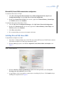
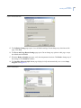
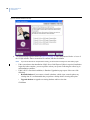
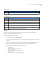
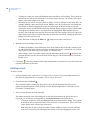
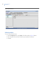
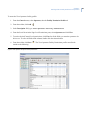
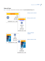
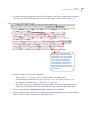
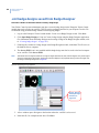
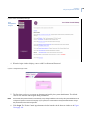
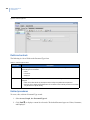
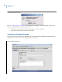
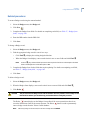
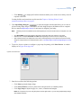
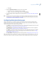
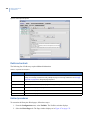
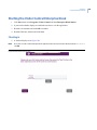
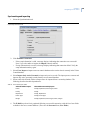
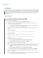
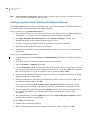
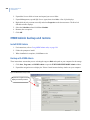
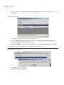
10. The SQL Server Installation Center page opens. Click Installation and then click New SQL
SERVER stand alone installation or add features to and existing installation as shown in Figure 1.
Chapter 1
Installing Visitor Central
Figure 1. SQL Server Installation Center
11. The Setup Support Rules page opens. When the operation is complete, click OK.
12. The Product Key page opens. If the product key is not already entered for you, enter the product key
and then click Next.
13. The License Terms page opens. Review the agreement, and then select I accept the license terms.
Click Next.
14. The Setup Support Files page opens and provides a list of components that are required for SQL
Server setup. Click Install.
15. The Setup Support Rules page opens and identifies problems that might occur when you install SQL
Server Setup support files. Click Next.
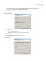
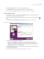
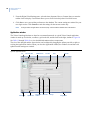
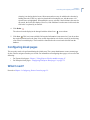
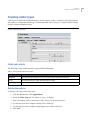
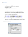
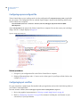
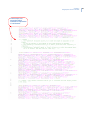
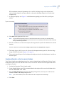
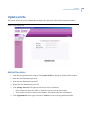
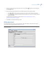
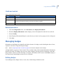
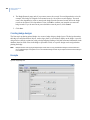
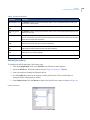
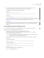
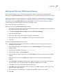
16. The Feature Selection page opens as shown in Figure 10. Select the following options, and then click
Next.
Instance Features:
•
•
Database Engine Services
Full-Text Search.
Shared Features:
•
•
•
•
Client Tools Connectivity
Client Tools Backwards Compatibility
Management Tools - Basic
Management Tools - Complete.
11
12
Visitor Central 1.5.1
User Manual
Figure 2. Feature Selection
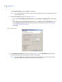
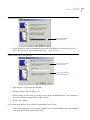
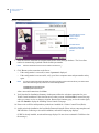
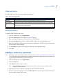
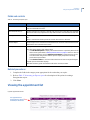
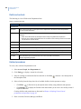
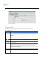
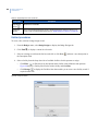
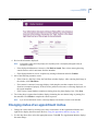
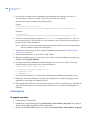
17. The Instance Configuration page opens. Select Named Instance, and then enter VCSQL. Click
Next. See Figure 3.
Note:
It is very important that you enter the correct instance for the appropriate product.
Figure 3. Instance Configuration
18. The Disk Space Requirements page opens. Click Next.
Chapter 1
Installing Visitor Central
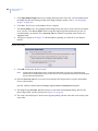
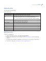
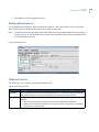
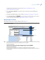
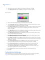
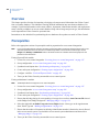
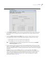
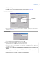
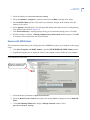
19. The Server Configuration page opens. Click the Service Accounts tab, and then configure settings as
follows: See Figure 4.
Click Use the same account for all SQL Server services to apply the same username and password
to the SQL Server Agent, SQL Server Database Engine and SQL Server Reporting Services.
Enter the following information, and then click OK:
•
•
Account Name: Enter Administrator or the domain account name.
Password: Enter the administrator password for this operating system.
Startup Type: Select Automatic for SQL Server Agent, SQL Server Database Engine, and SQL
Server Browser.
Click Next.
Figure 4. Server Configuration
20. The Database Engine Configuration page opens. Click the Account Provisioning tab, and then
configure the settings as follows: See Figure 5.
Authentication Mode: Click Mixed Mode (SQL Server authentication and Windows
authentication.
Built-in SQL Server system administrator account: In the Enter password field, enter the ‘sa’
password.
Specify SQL Server administrators: Click Add. The Select Users or Groups page opens as shown
in Figure 6. In the Enter the object names to select field, enter Administrator, and then click Check
Names to make sure you have entered the Administrator for this computer. Click OK to close the
Select Users or Groups page.
Click Next.
13
14
Visitor Central 1.5.1
User Manual
Figure 5. Database Engine Configuration
Figure 6. Select Users or Groups
21. The Error and Usage Reporting page opens. Click Next.
22. The Installation Rules page opens. Click Next.
23. The Ready to Install page opens. Click Install.
24. The Installation Progress page opens. When the setup process is complete, click Next.
25. The Complete page opens. Click Close.
26. We recommend that you restart your computer at this time.
Chapter 1
Installing Visitor Central
Microsoft SQL Server 2008 communication configuration
To enable the Protocols for VCSQL:
1. Click Start, All Programs, Microsoft SQL Server 2008, Configuration Tools, SQL Server
Configuration Manager, and then SQL Server Network Configuration.
2. Double-click Protocols for VCSQL. One at a time, right-click on Shared Memory, Named Pipes,
and TCP/IP, and then select Enabled.
To enable the Protocols for SQL Native Client:
1. From the SQL Server Configuration Manager, click SQL Native Client 10.0 Configuration.
2. Double-click Client Protocols. One at a time, right-click on Shared Memory, Named Pipes, and
TCP/IP, and then select Enabled.
3. Click File, and then Exit.
4. We recommend that you restart your computer at this time.
Installing Microsoft SQL Server 2005
To install Microsoft SQL Server 2005:
1. Insert Disc 1 of Microsoft SQL Server 2005 CD or the product DVD into the CD/DVD drive and wait
as the Microsoft SQL Server 2005 page automatically opens.
2. When the Start page opens, select Server components, tools, Books Online, and samples, as in
Figure 7.
Figure 7. .SQL Server 2005 Start
3. When the End User License Agreement page opens, review the agreement, select I accept the
licensing terms and conditions and click Next.
4. A page displays a list of prerequisites, required prior to installing SQL Server. Click Install to begin
installing the components as in Figure 8:
15
16
Visitor Central 1.5.1
User Manual
Figure 8. Installing Prerequisites
Note:
This process takes several minutes.
When the process is complete, click Next to continue.
5. A System Configuration Check page opens. This page requires no user action. Please wait.
6. A Welcome to the Microsoft SQL Server Installation Wizard opens. Click Next to continue.
7. A second System Configuration Check displays. Please wait as the system processes a list of
potential installation problems. Do not change anything on this page. When the system check is
finished, click Next to continue.
8. A Windows Installer page displays briefly. No user action is required.
9. A Microsoft SQL Server Installation page displays a progress bar as setup is preparing to continue
with the installation. No user action is required.
10. The Registration Information page displays as in Figure 9.
Figure 9. Registration Information
Chapter 1
Installing Visitor Central
Enter a name, company, and the 25-character Product Key found on the yellow sticker in the CD
liner notes or the CD sleeve. Verify your entry and click Next.
11. A Components to Install page opens as shown in Figure 10 on page 17.
Figure 10. Components to Install
Select two items:
•
•
SQL Server Database Services
Workstation components, Books Online and development tools.
Click Next.
12. An Instance Name page opens as shown in Figure 11.
Figure 11. Instance Name
17
18
Visitor Central 1.5.1
User Manual
Select Named Instance and enter VCSQL. Click Next.
Note:
It is very important that you enter the correct instance for the appropriate product. In the example above, the
product is Visitor Central.
13. A Service Account page opens as shown in Figure 12.
•
•
•
If you select Use the built-in System account, verify that Local system displays in the dialog
box.
In the Start services at the end of setup grouping, select SQL Server and SQL Browser. If you
select SQL Server Agent at this time, you do not have to set properties later, as in Setting SQL
Server Agent Properties on page 20.
Click Next.
Figure 12. Service Account
14. An Authentication Mode page opens as shown in Figure 13. Select Mixed Mode and enter the sa
password, then enter the password again to confirm. Click Next.
Note:
We strongly suggest that you assign a unique password of your choice. This is the sa user password, used
later in the installation of your application, during creation of the database.
Chapter 1
Installing Visitor Central
Figure 13. Authentication Mode
15. The Collation Settings page opens. Leave all default settings. Do not change any selections on this
page. Click Next.
16. The Error and Usage Report Settings page opens. Do not change any options on this page. Accept
the defaults and click Next.
17. When the Ready to Install page opens, verify the components selections. Click Back to change any of
the settings or click Install to continue.
18. The Installing Microsoft SQL Server page displays briefly and automatically moves on to Setup
Progress as in Figure 14.
Figure 14. Setup Progress
19
20
Visitor Central 1.5.1
User Manual
A checklist displays as components are configured and validated. A status column indicates the
progress. When the process is finished, click Next.
Note:
This process takes quite come time. During the process, a message displays, requesting that you insert Disc 2
of the SQL Server 2005. Insert Disc 2 and click OK. Please wait. (This does not apply if you are installing from a
DVD.)
19. The Completing Microsoft SQL Server 2005 Setup page opens. A list of setup logs displays sources
of information describing the configuration. Review the list and click Finish to exit the Installation
Wizard.
20. We recommend that you reboot your computer at this time.
Install SQL 2005 Service Pack 2
Service Pack 2 is required. If it is not currently installed, you will need to do so now.
1. Download Microsoft SQL 2005 Service Pack 2 from the Microsoft download Website.
2. Follow the on-screen instructions. When prompted, make sure that you select the VCSQL instance.
3. After the installation is complete, the SQL Server 2005 User Provisioning Tool for Vista page opens.
Click Cancel.
4. We recommend that you restart your computer at this time.
Setting SQL Server Agent Properties
By default, the SQL Server Agent service is disabled when SQL Server 2005 is installed. This service must be
running to keep the databases in optimal condition.
Note:
See Step 13. A Service Account page opens as shown in Figure 12. on page 18. If you selected SQL Server Agent on the
Service Account window, you do not have to set Server Agent properties at this time.
1. Right-click My Computer on your desktop and select Manage.
2. In the Computer Management page, expand Services and Applications and then expand Services to
display the list of services on your computer.
3. Select and right-click SQL Server Agent (VCSQL), where VCSQL is used in this example.
4. Select Properties to open the Properties page.
5. In the Startup type, select Automatic from the drop-down list.
6. Click OK.
7. We recommend that you reboot your computer at this time.
Chapter 1
Installing Visitor Central
Installing Microsoft SQL Server 2000
Note:
SQL Server 2000 is only supported for existing installations and not for new Visitor Central 1.5.1 installations.
If you have a Server computer that you are using for the Visitor Central installation and database, you must
install Microsoft SQL Server 2000 at this time. The SQL Server program stores and controls the Visitor Central
databases. Install according to your environment and manufacturer’s instructions.
To successfully install Microsoft SQL Server:
Note:
1. FOR EXISTING SQL USERS: If you have an existing SQL instance on your computer,
you are required to install another instance named VCSQL.
2. Visitor Central does not support a divided file share system.
3. The SQL Server software is user supplied and is not included as part of a Visitor Central system.
4. If you purchased this system from GE, SQL Server is installed and configured for you.
1. We recommend that you select Read the Release Notes. This displays the Microsoft SQL Server 2000
Readme file, in Notepad.
2. IMPORTANT: During installation, enter VCSQL in the Instance Name field.
3. From the Authentication Mode page, you MUST select Mixed Mode (Windows Authentication and
SQL Server Authentication).
4. IMPORTANT: In ‘Add Password for the ‘sa’ login,’ enter master or create a unique password as the
password for the administrator account. Enter a second time to confirm. (If you purchased your Visitor
Central system from GE, a temporary password of master was assigned.)
Note:
We strongly suggest that you assign a unique password of your choice.
This is the ‘sa’ user password, used later in the installation, during creation of the Visitor Central database.
Write the password down, then store it in a safe place as you are asked for it again later.
5. You must shut down and restart your computer in order for the installation to take effect.
For additional information, consult your Microsoft documentation.
Installing Microsoft SQL Server 2000 Service Pack 4
Note:
We recommend that you install the Microsoft SQL Server 2000 Service Pack 4 before you begin your installation of
Visitor Central.
Obtain Microsoft SQL Server 2000 Service Pack 4
If you install the Service Pack outside of the Visitor Central installation, this is an abbreviated list of
instructions to assist you.
To obtain a copy of Microsoft SQL Server 2000 Service Pack 4, use one of the following methods:
1. Web download
2. Microsoft product CD
21
22
Visitor Central 1.5.1
User Manual
Each method is detailed in the following sections.
Web download
To download Microsoft SQL Server 2000 Service Pack 4 from the Web:
1. In Internet Explorer, navigate to the Microsoft Web site. Locate the Download Center and search for
Service Pack 4.
2. Open the link for the appropriate download.
3. When the associated download page displays, scroll down to the list of files in this download.
4. Click to download the file to a temporary directory on your local computer.
5. Navigate to where you placed the contents of the service pack and execute the setup.bat file.
Product CD
To install Microsoft SQL Server 2000 Service Pack 4 from the Microsoft product CD:
1. Back up the SQL databases: master, model, and msdb.
2. Insert the Microsoft Updates CD into your CD-ROM drive.
3. Navigate to the CD drive, locate the file, and double-click to unpack the files to your computer.
4. Navigate to where you placed the contents of the service pack and execute the setup.bat file.
Installing Microsoft SQL Server 2000 Service Pack 4
To install SQL Server Service Pack 4 on a typical Server/Client Architecture:
1. After a successful download, installation begins. Accept the terms and conditions as listed in the EndUser License Agreement.
2. Proceed to copy and install the driver on as many computers within your Visitor Central system as
needed.
3. Follow instructions as prompted, using the recommended choices as described during the installation
process.
Note:
You must select your SQL instance name as VCSQL as in Figure
15 on page 23.
Chapter 1
Installing Visitor Central
Figure 15. SQL instance name
You must enter the SQL
instance name here.
4. When requested to select the authentication mode that setup should use to connect to SQL Server,
select ‘The SQL Server system administrator login. . .’as in Figure 16.
Figure 16. Connect to Server - enter sa password
Select here and enter
the ‘sa’ password.
This is the default. DO
NOT use this selection.
5. Enter the SQL ‘sa’ password and click Next.
6. Installation takes some time. Please wait.
7. When complete, AGAIN, back up your SQL master, model, and msdb databases, since installation of
the Service Pack has updated and altered their contents.
8. Restart your computer.
If you do not install the SQL Service Pack before installing Visitor Central:
1. If the system detects that it is not currently installed, Visitor Central installation stops and installation
of the SQL Service Pack automatically begins.
23
24
Visitor Central 1.5.1
User Manual
2. Follow instructions as prompted, using the recommended choices as described during the installation
process.
3. When requested, enter the SQL ‘sa’ password.
4. Installation takes some time. Please wait.
5. Following the Service Pack installation, your computer automatically restarts.
6. Log on as the administrator user and installation resumes, continuing from the point at which you left
off.
Microsoft SQL Server verification
When restarted, the system automatically starts SQL Server. Log on as administrator. You may want to verify
the installation. You have two options available:
•
•
Check the taskbar.
Check the Services Form.
Verify SQL installation using the taskbar
To verify that SQL Server service is running:
In the taskbar status area, an icon displays a computer with a green arrow.
Verify SQL installation using the services form
To verify SQL Server using the Services page:
1. Click Start, then choose Programs, Administrative Tools, and then Component Services.
2. Click Services (Local).
3. Locate the service for SQL Server with the VCSQL instance name.
•
•
The status should read ‘Started’ which means that the service is running.
If status is blank, then the service is not running. You cannot proceed with the installation unless
the service is running. Check your SQL Server documentation for more information on
troubleshooting. Exit the page.
Chapter 1
Installing Visitor Central
Sample Visitor Central deployment scenario
Figure 17. Database, Server, client application, and all modules access the same Web Server
25
26
Visitor Central 1.5.1
User Manual
Installing Visitor Central software
1. You MUST be logged on as the local administrator user. If not, log off and log back on as a user with
these permissions. If you are logging onto a domain environment, log off and log on as administrator
to the local computer. (If the computer is a domain controller, log on as an administrator to the
domain.)
2. Insert the Visitor Central CD into the CD-ROM drive. If the CD does not launch automatically, you
must manually start the software. Double-click (or run) VisitorCentral.exe.
3. Select install to display the installation options or documentation to display the documentation
options. We recommend that you review the documentation before you begin your installation.
4. When you have finished reviewing the documentation, select Install Software.
5. The Visitor Central CD main menu page opens as shown in Figure 18.
•
•
•
Install Visitor Central Server: Installs the Visitor Central Server.
Install Visitor Central Client: Installs the Visitor Central Client. We recommend using Webtop
for Client/Kiosk installations.
Install Microsoft SQL Server 2008 Express Edition: Installs SQL Server 2008 Express Edition.
SQL Server 2008 Express Edition is automatically installed during new installations of Visitor
Central if no other VCSQL instance is detected.
Figure 18. Visitor Central CD main menu
6. Continue with “Installing Visitor Central server” on page 27.
Chapter 1
Installing Visitor Central
Installing Visitor Central server
1. At the Visitor Central main menu, click Install Visitor Central Server. This begins the Server
installation.
Note:
SQL Server 2008 Express Edition is included as part of the installation. If you want to use SQL Server Standard
or Enterprise instead of Express, you must install it before starting the Visitor Central installation.
2. Following the extraction of files to your computer, the Introduction page opens as shown in Figure 19.
Read the information on the Introduction page, and then click Next.
Figure 19. Introduction
3. The License Agreement page opens. Select to accept the terms of the license agreement and click
Next.
4. The Choose Install Folder page opens. Accept the default installation folder or click Choose to
navigate to another destination. Click Next to continue.
5. The Database Installation and Setup page opens as shown in Figure 20. Select the type of database that
you are going to use, and then click Next.
27
28
Visitor Central 1.5.1
User Manual
Figure 20. Database installation and setup
6.
The Password page opens as shown in Figure 21 on page 29. Enter the password for the ‘sa’ user of
the VCSQL instance. Enter a second time to confirm, and then click Next.
Note:
•
•
If you do not enter the sa user password correctly, you will receive a message to re-enter and try again.
If the system detects that installation of SQL Server 2008 Express Edition is required, installation
begins and when complete, you are required to reboot your system. Following the reboot, log in
and installation continues.
If this is NOT a first-time installation, A Database Upgradation page opens. Select one of the
following:
• Reinstall database if you want to re-install a database, which wipes out and replaces any
existing data. It is recommended that you perform a backup before selecting this option.
• Upgrade database to upgrade an existing database and leave the data.
Click Next.
Chapter 1
Installing Visitor Central
Figure 21. sa user password
7. The Get User Input page opens. Select the appropriate drive letter for your database. This may be
applicable if you have a divided hard drive. For a typical installation, accept the default directories as
displayed, and then click Next.
8.
The Pre-Installation Summary page opens. Verify that the page reflects the selections appropriate for
your Visitor Central installation. If the selections are not what you want, click Previous to return to the
page that you want to review or change a selection.
Click Install to begin installation.
A series of windows displays as the listed components automatically install if not already there. The
following components will require a restart.
•
•
•
•
.NET Framework
SQL Server 2008 Express
PowerShell
Windows Installer
9. Files are copied to your computer and a database is created. When installation is complete, the
Installation Complete page opens. Click Done.
10. Your computer automatically restarts and you have completed the installation process.
11. Log on and continue with “Licensing Visitor Central” .
29
30
Visitor Central 1.5.1
User Manual
Licensing Visitor Central
Visitor Central includes a copy-protection mechanism that requires a software license key. The license key
controls the following:
•
•
•
•
Number of Visitor Central Server computers
Number of client license computers connected to the Server computer at the same time
Expiration date of the license
Access control capabilities
License your Visitor Central application as follows:
1. After installing Visitor Central, click Start, then select Programs, Visitor Central, and then VC
License Manager to display the Visitor Central License Manager as in Figure 22.
Figure 22. License Manager
Machine code
License code
Component
windowpane
2. To complete the License Manager for Visitor Central, call GE at 1-888-GESECURITY or
1-888-437-3287. Provide the following information:
•
•
•
•
•
Customer company name and address
Business Partner name and address
Sales Order number
10-character Machine Code, as displayed in the License Manager window, identifying your
system. Your computer must be enabled for use in the way that you will be using Visitor Central.
• If it is to be networked, this computer should be online when you access the machine code.
• If it is to be standalone, the computer should be in that state when capturing the machine code.
• Exit all other applications before capturing the machine code.
• If the computer has wireless access, disable before capturing the machine code.
Product bar code number
Chapter 1
Installing Visitor Central
•
Things to note before calling in your machine code
7. In response, Customer Support provides an e-mail response with a 40-character license key code.
8. In the License code box, enter the license key code as provided by Customer Support.
9. Click Save License.
10. The License Manager windowpane displays a window similar to Figure 23.
Figure 23. License Manager complete
11. Click OK on the message dialog and close the Visitor Central License Manager page.
12. Store a hard copy of your license key in a secure place, so that if the license key is ever destroyed or
corrupted, you can reinstall without having to contact GE.
Note:
If you have not already done so, you must reboot your computer at this time.
13. Continue with “Installing Visitor Central client” on page 32.
31
32
Visitor Central 1.5.1
User Manual
Installing Visitor Central client
Note:
•
•
You must license your Visitor Central Server before you can install Visitor Central Client.
When you select a Typical type of installation, the Administrator’s module installs.
When you select a Custom type of installation, a second window displays to select the type of kiosk
that you want to install as either an Appointment Kiosk or an Express Kiosk, in addition to the
Administrator’s module.
Any Windows Vista or Windows XP professional computer can install Visitor Central Client software and
access Visitor Central with Web access to the Visitor Central Server computer or using the Visitor Central
Installation CD.
Prerequisites
These items are required for imaging kiosks. Active links display on the Visitor Central Webtop home page
after logon for your convenience in downloading and installation of the following:
•
•
•
•
•
•
•
Java 6 update 13*
JMF imaging component*
Flash Plug-in*
CSSN Driver Licenses and Pasports SDK*
.Net Framework*
Drivers for the Topaz SignatureGem Tablet
If your Visitor Central system uses a firewall (such as BlackICE) for network communication, you
may need to disable the firewall or add Visitor Central to the firewall application exceptions list.
*
Automatically installs during Visitor Central client CD installation
To install from the Visitor Central CD
Note:
We recommend installing Clients/Kiosks from the Webtop home page. However, you have the option of installing from
the CD main menu.
1. Insert the Visitor Central CD into the CD-ROM drive. If the CD does not launch automatically, you
must manually start the software. Double-click (or run) VisitorCentral.exe.
2. Select Install Software to display the Visitor Central CD main menu.
3. Select Install Visitor Central Client.
4. Follow on-screen instructions and continue with “When installation begins” on page 33.
To install from the Visitor Central Server
1. Navigate to the Visitor Central Server at http://hostname:8080/vcserver where hostname
equals the name of the computer that is hosting the Visitor Central application.
2. Review all selections and install applicable files for your Windows Platform and system environment.
Follow on-screen instructions as the files install on your computer.
Chapter 1
Installing Visitor Central
3. Click Visitor Central Client on the Visitor Central Webtop home page.
4. Click Start Installer when the recommended installation for your platform displays.
5. Follow on-screen instructions and continue with “When installation begins” on page 33.
When installation begins
1. Following the copy of files to your computer, the Introduction page opens. Read the information on
the Introduction page, and then click Next to continue.
2. The License Agreement page opens. Select to accept the terms of the license agreement, and then click
Next.
3. The Select the Type of Installation to be performed page opens as shown in as in Figure 24.
Figure 24. Install client type
4. Select the type of installation, and then click Next.
•
•
When you select a Typical type of installation, only the Administrator’s module installs.
When you select a Custom type of installation, a second window displays to select the type of
installation that you want as either an Enterprise Kiosk or an Express Kiosk, in addition to the
Administrator’s module.You can select all modules.
5. A Choose Install Folder page opens. Accept the default installation folder or click Choose to navigate
to another destination. Click Next.
6. The Visitor Central Server Host page opens as shown in Figure 25 on page 34.
33
34
Visitor Central 1.5.1
User Manual
Figure 25. Visitor Central server host
Note that the Server name
cannot contain an
underscore(_).
Note that this test
connection to the Server
database has a status of
‘passed.’
7. Enter the Visitor Central Server computer name used to reach the SQL database. The Server Port
number is automatically populated with the default port number.
Note:
A Visitor Central Server name cannot contain an underscore (_).
8. Click Test to test the connection to the Server.
•
•
If the configuration is successful, a status of passed is displayed.
If the configuration is not successful, verify your Server computer name and port number and try
again.
Note:
You may be required to add the IP address and Client computer name to the hosts file of your Visitor Center
Server. The hosts file typically resides in one of the following folders:
C:\WINDOWS\system32\drivers\etc
C:\WINNT\system32\drivers\etc
After a successful connection, click Next.
9. Verify that the Pre-Installation Summary windowpane reflects the selections appropriate for your
Visitor Central installation. If the selections are not what you want, click Previous to return to the page
where you want to review or change a selection. Return to the Summary page, review the results again,
and click Install to display the Installing Visitor Central Client page.
10. Please wait as all files and dependency modules are installed for a Visitor Central Client (Kiosk).
11. At this point in the installation, the Java Media Framework installs. Please wait as setup completes and
JMF initializes. Following a successful installation, an Install Complete page displays.
(If JMF is already installed, an uninstall message displays. Do not select to uninstall. Click No to close
the message.)
Chapter 1
Installing Visitor Central
12. We recommend that you restart your computer at this time. Close all applications, remove any disks
from the disk drives, and click Done to restart computer.
13. Log in and continue.
What’s next?
Proceed to Chapter 2, Launching and navigating Visitor Central on page 37.
35
36
Visitor Central 1.5.1
User Manual
Chapter 2 Launching and navigating Visitor
Central
This chapter describes how to open the Web browser and launch Visitor Central.
Also included are instructions on how to navigate the Visitor Central
administrator’s module and a description of the common elements. Readers
should familiarize themselves with this chapter before proceeding to other
chapters in this document.
In this chapter:
Launching the application . . . . . . . . . . . . . . . . . . . . . . . . . . . . . . . . . . . 38
Selecting a Visitor Central module . . . . . . . . . . . . . . . . . . . . . . . . . . . . . 39
Logging on to Visitor Central administrator’s module. . . . . . . . . . . . . . 39
Navigating the Visitor Central administrator’s module . . . . . . . . . . . . . 40
Creating, editing, and deleting records . . . . . . . . . . . . . . . . . . . . . . . . . 49
Configuring kiosk pages . . . . . . . . . . . . . . . . . . . . . . . . . . . . . . . . . . . . . 51
What’s next? . . . . . . . . . . . . . . . . . . . . . . . . . . . . . . . . . . . . . . . . . . . . . . 51
38
Visitor Central 1.5.1
User Manual
Launching the application
1. On the desktop, open a browser that has a Java plug-in, for example, Internet Explorer.
2. Enter this URL to launch the Visitor Central Webtop home page:
http://hostname:8080/vcserver
where hostname equals the name of the computer that is hosting the Visitor Central application.
Figure 26. Visitor Central Webtop home page
Click to log on to Visitor Central
Administrator’s module.
Click to log on to Preregistration.
Click to log on to Express Check-in.
Click to access the User Manual.
Chapter 2
Launching and navigating Visitor Central
Selecting a Visitor Central module
You are ready to begin configuring your Visitor Central Kiosk. Each of the menu options below is discussed in
detail in the chapters that follow. Also, refer to “Following a sequence” on page x.
Starting Visitor Central application
To select a Visitor Central module and begin configuration, double-click the appropriate menu button on your
Visitor Central Webtop home page.
Click Visitor Central to log on to the Enterprise administrator’s module and
configure Visitor Central. Default user name is install, and the password is
install. Begin with Logging on to Visitor Central administrator’s module.
Click Preregistration to log on to the Preregistration module. This is an
abbreviated configuration module. Default user name is install, and the
password is install. See “Logging on to Preregistration” on page 114.
Click Express Checkin to open the Express Check-in module at an appropriate
workstation in readiness for visitors that DO NOT have an appointment. Read the
exit reminder and click OK to continue. See “Using Express Check-in module” on
page 87.
Click User Manual to open a PDF readme file of this document, the Visitor Central
User Manual.
Logging on to Visitor Central administrator’s module
1. Click Visitor Central in the upper left corner of the screen to display the login window.
3. Enter a valid Login ID and password. The first time you log on, you must use the name assigned by
your system administrator. The default value is case sensitive and assigned during installation.
Note:
A user Login ID of install, with password install, is automatically set up during installation to be used by the
System Administrator to configure the system. To ensure the integrity of your system, we recommend that
the System Administrator change this password after the initial configuration.
4. Click Log on. The Visitor Central application launches in the browser window.
Selecting a facility
After you log on, the Facility Set Manager window displays. Use this window to select the facility, which
allows you to view all the records associated with a specific facility. Multiple facilities can be selected and the
number of facilities listed depends on operator permissions.
39
40
Visitor Central 1.5.1
User Manual
To select a facility, click the facility name. To select multiple facilities, use the Shift key to select all the
records or the Ctrl key to make multiple selections from the list. See Table 4 for a description of the elements
of this window.
Table 4.
Facility Set Manager window
Element
Description
Facility List
Displays a list of facilities based on the facility profile.
Time Zone
Use the drop-down list to select the appropriate time zone. By default, when you log on to
Visitor Central, the Time Zone selected is that assigned to your Operator record. See Defining
operators on page 76 for more information.
Select All
Click to select all the facilities in the list.
Unselect All
Click to cancel the ‘Select All’ option.
Navigating the Visitor Central administrator’s module
When Visitor Central is initially launched in your browser window, the desktop is comprised of a primary
navigation menu bar, and a toolbar.
Figure 27. Visitor Central desktop
Menu bar
Each primary navigation menu item consists of secondary navigation items, each of which is an application or
a function. Only those applications to which an operator has permission, and only those actions that an operator
has permission to perform are available. Depending on those permissions, the following primary navigation
items are available: File, Access, Monitor, Configuration, Control, Reports, and Window.
See Table 5,File menu on page 41 through Table 11,Window menu on page 43 to view the secondary
navigation items and a description of their functions.
Chapter 2
Launching and navigating Visitor Central
Table 5.
File menu
Sub-Menu
Function
Facility Set...
Provides a list of facilities available for selection, based on the operator’s facility profiles.
Customize Toolbar...
Displays a list of applications from which you can select/deselect those that you want to display on
your toolbar.
Debug Levels...
Displays a list of packages. Debug levels can be set for each package to be used for troubleshooting.
The log file, avatar.log, is written to c:\avatar\logs.
Log off
Closes all windows and displays the Login screen.
Table 6.
Access menu
Sub-Menu
Form
Function
People
Personnel
Use to create and edit Personnel records that identify each badge holder.
Personnel Type
Use to create and edit Personnel Type records: to define different types of personnel that
are assigned to each badge holder.
Department
Use to create and edit Department records: to assign to each badge holder.
Banned
Reasons
Use to define reasons that an Express visitor may be banned from obtaining a badge.
Badges
Use to create and edit Badge records: to control the functions and capabilities of the
badge.
Badge Designs
Use to create and edit Badge design records used for printing.
Badge Formats
Use to create the type of bar code format to be used in your badge design.
Appointment
Use to schedule appointments for visitors.
Visitor Type
Use to create visitor types, such as contractors or special guests.
Visitor
Use to identify, create, or modify visitor records and enter contact information.
Watch List
Use to add visitors that require special attention or visitors that must be denied access.
Badges
Appointments
Table 7.
Monitor menu
Sub-Menu
Function
Appointment
Monitor
Use to view and manage appointments. Refer to “Using the appointment monitor” on page 146 and
details of the following:
“To check in a visitor that has an appointment:” on page 149
“To create an appointment and check in a visitor:” on page 150
“Checking in using the scanner” on page 157
“Watch list visitors” on page 157
41
42
Visitor Central 1.5.1
User Manual
Table 8.
Configuration menu
Sub-Menu
Function
Facilities
Use to create and edit Facility records that group your database records into meaningful units.
Default Kiosk Check-in
Use to select the default check-in field.
Kiosks
Use to configure an Enterprise Kiosk, import images, and page details.
Kiosk Pages
Use to create Enterprise Kiosk pages.
Clients
Use to manually add client workstations to the system.
Access Control
Integration
Use to integrate an access control database with Visitor Central.
Parameters
SMTP Server
Configuration
Setup
Use to enter host information for access control integration.
Synchronization
Use to import data tables and test the access control database connection.
Configure Person/Badge
Export
Use to establish a connection with the access control host and assign categories,
access rights, and user fields.
Default Password
Use to assign a default password for a newly created operator.
User Field Configuration
Use to allow entry from Appointment Monitor, Operator Check-in, Enterprise
Kiosk, or dynamic entry during a check-in.
Scanner Configuration
Use to configure which fields to scan and retain when scanning a driver’s license
or a passport.
Displayed Document
Use to configure a document or statement such as a non disclosure statement on
the monitor before a visitor checks in.
Use to set up the SMTP mail Server information.
SMTP Setup
Table 9.
Use to configure Visitor Central e-mail alert notifications.
Control menu
Sub-Menu
Function
Operators
Operators
Use to create and edit Operator records to define those individuals who log on to
the Visitor Central system.
Permissions
Use to create and edit Permission records that combine system, form, and facility
permission profiles. This permission is then assigned to an operator.
System Permissions
Profiles
Use to create and edit System Permission records that define the functions each
operator level is permitted to perform. The functions included on this form are
system related and are not filtered by facility.
Facility Permissions
Profiles
Use to create and edit Facility Permission Profile records that describe an
operator’s level of access to the various forms and fields. The functions included
on this form are filtered by facility.
Chapter 2
Launching and navigating Visitor Central
Table 10. Report menu
Sub-Menu
Function
Reports
Use to control which activities are stored in history and how to view, format, print, and save reports.
Table 11. Window menu
Sub-Menu
Function
Minimize All
Reduces all windows to an icon.
Restore All
Opens all minimized windows.
Cascade
Arranges windows in an overlapped fashion.
Tile
Horizontally
Arranges windows in non-overlapped tiles, one on top of the other.
Tile Vertically
Arranges windows in non-overlapped tiles, side-by-side.
Open
windows
Displays a list of open windows. The window that is currently active displays a check mark next to it. By
clicking on a window in this list, it becomes the active window.
Tool bar
The tool bar is user configurable and can be used to display your most frequently used applications.
Note:
Prior to configuration, the tool bar displays empty.
To add an application icon to the toolbar:
1. From the File menu, click Customize Toolbar.
2. The Customize Toolbar window displays a list of applications in Visitor Central and a list box of text
options.
3. From the list of applications, expand the directories and select/deselect those applications that you
want to display on your toolbar. Selecting the main branch selects all of the sub-branches.
4. From the list box of text options, select from the following:
•
•
•
Show text labels
The text label displays below the icon.
Selective text on right
The text label displays to the right of the icon.
No text labels
Only the icon displays. The icons include tooltips.
43
44
Visitor Central 1.5.1
User Manual
5. From the Digital Clock Settings pane, select the time (Operator, Host, or Custom) that you want the
toolbar clock to display. Custom time allows you to select from a drop-down list of time zones.
6. Click Save to save your toolbar preferences to the database. The current settings are retained for your
next login session. Click Cancel to retain the settings for the current session only.
Note:
If a large number of applications are selected, they could exceed the viewable area of the monitor.
Application window
The Visitor Central applications are based on a common framework. A typical Visitor Central application
window is made up of a title bar, a toolbar, a grid on the left, and the form on the right, similar to Figure 28.
See Table 12 through Table 18 to view detailed information on these components.
The size of the data grid and the form window can be adjusted by dragging the splitter pane left or right, or
resizing the Application window. When you close the Application window, the window size and last-used
splitter location settings are retained.
Figure 28. Application Window
Grid
Results Tab
Shortcut Links
Splitter Pane
Tabbed Panes
Drop-down
List Box
Tool Bar
Filter List
Form
Title Bar
Manage
Progress Bar
Chapter 2
Launching and navigating Visitor Central
Table 12. Title bar
Item
Description
Title Bar
The Title Bar displays across the top of the window. It displays the label of the primary navigation menu item and
contains three buttons:
• Minimize: Click to resize your window to a smaller size.
• Maximize: Click to resize your window to a larger size.
• Close: Click to exit the window.
Table 13. Tool bar
Item
Find
New
Copy
Description
Click to locate specific data records based on selection criteria entered into any of the fields. This is useful if you
want to change data of an existing record. If you click Find without entering any search criteria, the system
finds all of the data records in that table. The records found for the search are displayed in the grid to the left of
the form. You must have View record permission to perform a search.
Click to add a new record as the last row in the record list. Any default values are filled in or cleared if there is no
default. You must have Insert record permission to create a new record and Update permission for all required
fields.
Click to create a new record and copy the values of the currently selected record to it. This is a quick way to
create a new record that is similar to an existing record. A record must be currently selected in order to copy it.
If multiple records are selected, a new record is created for each one selected. The copied records are placed at
the bottom of the record list and marked with the new record icon. You must have Insert record permission to
copy a record. Only fields for which you have permission are copied to the new record.
Save
Click to save the data record currently displayed to the database. If you have created a new record, it is added
to the database. If you displayed an existing record and made changes to it, this new version replaces the old
record in the database. You must have Update record permission to save any changes.
Delete
Click to mark the record currently displayed for deletion. The record is deleted from the database upon saving.
You must have Delete record permission to mark a record for deletion and the record table must support
deletion. If the record has record dependencies, a list displays indicating those records that are dependent on it.
Undo
Click to cancel the previous action and restore the values of the previously edited data.
Clear
Click to clear the fields and selections on the form. All option settings are set to an unselected state.
Print
Click to print records in a tabular or form format to your default printer.
Preferences
Help
Click to display the Preferences form that allows you to reposition and filter the grid columns, as well as
reposition the entire grid.
Click to access the Visitor Central User manual.
45
46
Visitor Central 1.5.1
User Manual
Table 14. Data grid
Item
Description
Grid
The record list window, or data grid, shows the results of search operations and allows you to quickly navigate
through the records found by a search. The data displayed in the grid columns consists of one or more fields of
the Visitor Central database table that is being manipulated. The number and order of the fields displayed, as well
as the placement of the grid on the screen (left, right, top, or bottom), is configurable by clicking Preferences on
the form tool bar. When an application is started, the record list window is initially empty.
You use the data grid mainly for record navigation. A single record or multiple records may be selected for
manipulation. Each row in the data grid represents a record. The records are obtained by performing a search, by
creating a new record, or by copying a record. When a search is performed, the grid is filled with all of the records
matching the search criteria. All previous records that were in the grid are removed. When adding new records,
the records are placed at the bottom of the grid, and are marked with the new record icon
.
Clicking on a single row in the grid highlights and selects that record for editing. The keyboard up and down
arrows can also be used to move from one record to the next. The record's field values display in the various
pages of the form. If any field value is changed, the Edit icon
displays next to the row.
More than one row can be selected in order to change a value for multiple records at one time, for example,
updating a time value for all records. Multiple rows can be selected by left-clicking the first desired record, then
dragging the mouse, and releasing it on the last desired record. Non-connected rows may be added to the
selection by holding down the CTRL key on the keyboard while selecting the row with the mouse. All selected rows
are highlighted. When multiple rows are selected, the pages of the form window are cleared and the values
replaced by asterisks. Changing a field value changes it for all selected records. If any field value is changed, the
Edit icon
displays next to the selected rows.
Table 15. Form
Item
Description
Form
The Form window provides the primary interaction between an operator and an application. It allows direct
access to all fields within a single record or a selection of records from a host database table.
Table 16. Progress bar
Item
Description
Progress Bar
The current status of operations performed.
Table 17. Status bar
Item
Description
Status
The number of records retrieved as well as any errors encountered during creation are displayed here.
Chapter 2
Launching and navigating Visitor Central
Table 18. Drop-down lists
Item
Description
Drop-down List
A drop-down list box has an arrow at the right of the box, and when clicked, displays a pick-list of options.
The contents of a pick-list consist of items you added using other forms.
Example: If you have not defined any watch lists in the system (using the Watch list form), the Watch list
drop-down pick-list on the Visitor form is empty.
Selecting an item from a drop-down list limits the search to records with matching selections. Drop-down
lists auto-complete, allowing you to type in leading characters of a desired item to jump to that point. A
blank or an empty drop-down list does not limit the search.
Manage
Visitor Central forms contain various drop-down list boxes, such as Facility, Type, Watch List, and so on,
that are populated with records created from other Visitor Central forms. The Manage button next to these
list boxes allows you to access the appropriate form and create or delete records. You must have Manage
permission to perform this function.
Filter
Visitor Central forms contain various drop-down list boxes, such as Facility, Type, Watch List, and so on,
that are populated with records created from other Visitor Central forms. The Filter button next to these list
boxes allows you to filter the list by description and/or facility using wildcards and operators as described
in “Search criteria” on page 47. From the results of the search, select and click OK.
Search criteria
When performing a search for data, you may want to view all records or only certain records. Prior to clicking
Find
, search criteria may be entered as follows:
Text boxes
•
•
•
A blank text box returns all records.
A text box containing text only returns records that contain the text specified.
Wildcards and operators can be used to help delimit the search. For instance, the asterisk can expand
the search in either direction around a string of characters.
Table 19. Wildcards and operators
Item
Function
Son*
The system finds any records beginning with “Son” such as Sonesta, Sonya, Sonny.
*son
The system finds any records ending with “son” such as Robinson, Jackson, Nelson.
*son*
The system finds any records containing “son” such as Masonry, Seasonal, Personnel.
Other symbols and their functions include the following:
Table 20. Other symbols
Symbol
Function
Equal to (no symbol required)
!
Not equal to
47
48
Visitor Central 1.5.1
User Manual
Table 20. Other symbols (continued)
Symbol
Function
>
Greater than
<
Less than
*
Match string
?
Match a single character
&
Logical and
|
Logical or
>=
Greater than or equal to
<=
Less than or equal to
Radio buttons
•
Selecting radio buttons limits the search to records with matching selections.
Check boxes
•
•
•
Enabling a check box limits the search to those records that have those options enabled.
Disabling a check box limits the search to those records that have those options disabled.
Leaving the check box as is, with the ?, indicates the value in this field does not participate in the
search.
Schedule control
•
•
When searching for scheduled events when an Event Time is selected, a specific time of the day must
be entered. The search returns only those records that contain a start time that matches the time
entered.
To search for scheduled events based on any time of the day, do not select the At time/mode buttons.
Select the days of the week for which scheduled events are desired, then click Find.
Drop-down lists
•
•
Selecting an item from a drop-down list limits the search to records with matching selections. Dropdown lists auto-complete, allowing you to type in leading characters of a desired item to jump to that
point.
A blank or an empty drop-down list does not limit the search.
List window
•
•
Adding an item from the Available window to the Selected window limits the search to those records
with matching selections.
If more than one item is selected, the search is limited to those records containing all of the selected
items in the exact order shown.
Note:
A blank Selected window does not limit the search.
Chapter 2
Launching and navigating Visitor Central
Creating, editing, and deleting records
All Visitor Central forms use a standard method to add, edit, or delete records.
Creating records
To create a record:
1. From the Primary menu, such as Access, Configuration, or Control, select a Secondary menu item,
then click the appropriate tab. For example: Access, People, Personnel.
2. Click New
.
The record list window, or data grid, displays a row marked with the error record icon
. If a
search has been performed, the grid is filled with all of the records matching the search criteria.
When adding new records, the records are placed at the bottom of the grid, and are marked with
the error record icon .
3. Complete the form.
A detailed explanation of each field on the form can be found on the Fields and Controls section
for each form in this guide. Because all Visitor Central forms are user-customizable, not all fields
may display on your form or they may display in a different order. All required fields are indicated
by red text. When all required information is complete, the Error icon
is replaced by the new
record icon
and the Save
icon is enabled.
4. Click Save
. This icon is disabled if all required information is not entered or if you do not have the
required permissions for the form.
Editing records
To edit a record:
1. From the Primary menu, such as Access, Configuration, or Control, select a Secondary menu item,
then click the appropriate tab. For example: Access, People, Personnel.
2. From the tool bar, click Find
.
The record list window, or data grid, shows the results of search operations and allows you to
quickly navigate through the records found by a search. When an application is started, the record
list window is initially empty.
3. Select a record from the list in the data grid.
•
The number and order of the fields displayed, as well as the placement of the grid on the screen
(left, right, top, or bottom), is configurable by clicking Preferences
on the form tool bar.
49
50
Visitor Central 1.5.1
User Manual
•
•
•
Clicking on a single row in the grid highlights and selects that record for editing. The keyboard up
and down arrows can also be used to move from one record to the next. The record’s field values
display in the various pages of the form.
More than one row can be selected in order to change a value for multiple records at one time, for
example, updating a time value for all records. Multiple rows can be selected by left-clicking the
first desired record, then dragging the mouse, and releasing it on the last desired record. Nonconnected rows may be added to the selection by holding down the Ctrl key on the keyboard while
selecting the row with the mouse. All selected rows are highlighted. When multiple rows are
selected, if the field data is the same for all records, the field value displays. However, if the field
data is not the same in all records the field value is replaced by an asterisk. Changing a field value
changes it for all selected records.
If any field value is changed, the Edit icon
displays next to the selected rows.
4. Make the necessary changes to the form.
•
•
A detailed explanation of each field on the form can be found on the Fields and Controls section
for each form in this guide. Because all Visitor Central forms are user-customizable, not all fields
may display on your form or they may display in a different order.
When editing a form, if you fail to supply required information, the Error icon
displays in the
Function tab label as well as next to the record in the data grid. The field that requires correction is
labeled in red.
5. Click Save
. This icon is disabled if all required information is not entered or if you do not have the
required permissions for the form.
Deleting records
To delete a record:
1. From the Primary menu, such as Access, Configuration, or Control, select a Secondary menu item,
then click the appropriate tab. For example: Access, People, Personnel.
2. From the tool bar, click Find
.
The record list window, or data grid, shows the results of search operations and allows you to
quickly navigate through the records found by a search. When an application is started, the record
list window is initially empty.
3. Select a record from the list in the data grid.
The number and order of the fields displayed, as well as the placement of the grid on the screen
(left, right, top, or bottom), is configurable by clicking Preferences on the form tool bar.
•
•
Clicking on a single row in the grid highlights and selects that record for editing. The keyboard
up and down arrows can also be used to move from one record to the next. The record’s field
values display in the various pages of the form.
More than one row can be selected in order to delete multiple records at one time. Multiple
rows can be selected by left-clicking the first desired record, then dragging the mouse, and
Chapter 2
Launching and navigating Visitor Central
releasing it on the last desired record. Non-connected rows may be added to the selection by
holding down the CTRL key on the keyboard while selecting the row with the mouse. All
selected rows are highlighted. When multiple rows are selected, if the field data is the same for
all records, the field value displays. However, if the field data is not the same in all records the
field value is replaced by an asterisk.
4. Click Delete
.
The selected records display in the data grid with the deleted icon
next to them.
5. Click Save . This icon is not available if all required information is not entered or if you do not have
the required permissions for the form. If any record dependencies exist for the record you are deleting,
a list of those records displays. The list must be cleared before the record can be deleted from the
database.
Configuring kiosk pages
This step only needs to be performed during the initial setup. The system administrator creates custom pages
for the visitor to navigate when they use a kiosk. For information on configuring these pages, refer to one of the
following:
•
•
For Express kiosk pages: Chapter 5, Using Express Check-in module on page 87
For Enterprise kiosk pages: “Configuring Enterprise Kiosk pages” on page 173
What’s next?
Proceed to Chapter 3. Configuring Visitor Central on page 53.
51
52
Visitor Central 1.5.1
User Manual
Chapter 3 Configuring Visitor Central
After the product installation is complete, there are a few additional steps to
complete before you begin using Visitor Central. System administrators should be
familiar with the information in this chapter. Also, refer to “Following a
sequence” on page x.
In this chapter:
Checklist . . . . . . . . . . . . . . . . . . . . . . . . . . . . . . . . . . . . . . . . . . . . . . . . . 54
Creating facilities . . . . . . . . . . . . . . . . . . . . . . . . . . . . . . . . . . . . . . . . . . 55
Creating visitor types . . . . . . . . . . . . . . . . . . . . . . . . . . . . . . . . . . . . . . . 57
Creating watch lists . . . . . . . . . . . . . . . . . . . . . . . . . . . . . . . . . . . . . . . . 58
Adding a visitor to a watch list . . . . . . . . . . . . . . . . . . . . . . . . . . . . . . . . 59
Adding clients . . . . . . . . . . . . . . . . . . . . . . . . . . . . . . . . . . . . . . . . . . . . . 60
Configuring SMTP server. . . . . . . . . . . . . . . . . . . . . . . . . . . . . . . . . . . . 63
What’s next? . . . . . . . . . . . . . . . . . . . . . . . . . . . . . . . . . . . . . . . . . . . . . . 64
54
Visitor Central 1.5.1
User Manual
Checklist
Use this checklist to configure Visitor Central.
Step
Description
For Express Kiosks:
Configure Express Kiosks for visitors without appointments. Refer to “Using Express Check-in module”
on page 87.
Configure visitor types and badge design for visitor types using the .xml file. See “Configuring .xml files”
on page 89.
Host and Attendant tasks
For Express Kiosk visitors (no appointment necessary):
Generate an express report of checked in and checked out visitors. The operator may want to generate
a report before beginning the Preregistration process. Refer to “Generating an Express report” on
page 118. (For a more advanced report based on database queries, refer to “Creating database reports”
on page 182.)
Click Status Changer in Preregistration to check visitor out when the visitor leaves. See “Express status
changer” on page 118.
Direct the visitor to the Express Kiosk workstation. The visitor completes the entire transaction. The
badge prints to the Visitor Central default printer. See “Checking in” on page 108.
Assist if visitor has problems or is banned from checking in. See “Banned visitors” on page 110.
For Administrator’s Module:
Create visitor types, such as VIP, contractors, 1-day Visitor, 3-day Visitor. Use as many visitor types as
needed to identify the various groups or persons visiting the facility.
• See "Creating visitor types" on page 57.
• See "Creating watch lists" on page 58.
Configure the client systems. See "Adding clients" on page 60.
Create facilities.
• See "Creating facilities" on page 55. A permission profile must be assigned when new facilities are
created.
• Review the facility permission profiles and make any necessary changes. See "Creating facility
permission profiles" on page 68.
• See "Configuring permissions" on page 74 for more information.
Review the system permission profiles and make any necessary changes. See "Creating system
permission profiles" on page 71.
Define Visitor Central operators, such as system administrators, badge administrators, hosts, and
attendants. See "Defining operators" on page 76.
Add the employees identified as host that make visitor appointments. See "People overview" on
page 128.
Create watch lists for VIPs or visitors banned from entering the facility.
• See “Defining banned reasons” on page 137.
Chapter 3
Configuring Visitor Central
Step
Description
Design badges for the different visitor types. Use different colors or badge orientation to distinguish
visitor types. See Managing badges on page 159.
Configure Enterprise kiosks for visitors with appointments. Add the company name, logo, text, and
colors to customize the kiosk. See "Customizing the Enterprise Kiosk" on page 174.
For existing appointments in the database:
Add the visitor’s name and contact information to Visitor Central. If this person has visited previously,
use the Search icon to locate their information. See "Adding visitor contact information" on page 141.
Create an appointment with the date and time of their arrival and departure. See "Making an
appointment" on page 143.
Assign the visitor to the appointment using the Invitee List. See "Assigning visitors to appointments" on
page 145.
When the visitor arrives, use the Appointment Monitor to retrieve the appointment and change the
status from pending to arrive. See "Using the appointment monitor" on page 146.
When the visitor leaves, use the Appointment Monitor to change their status from arrived to departed.
Review the appointments at the end of the day. Change the status to no show, if the visitor did not
arrive. See "Using the appointment monitor" on page 146.
Print the visitor’s badge. See "Printing a visitor badge" on page 151.
Generate a report. The report may include the visitor’s name, time of arrival and departure, and the
names of the visitors that did not show. See "Creating a report" on page 184.
Creating facilities
The facilities feature partitions the Visitor Central database into logical groupings. As a result of partitioning,
employees and attendants assigned to a specific facility might be permitted to view or have access to items
associated with only that facility, and not others.
During the installation process, a Global facility is created and by default, all database records are assigned to
that facility. Use the Facilities window to create additional records or delete records. These records, combined
with facility profiles and permissions, allow you to restrict operator access to records assigned to those
facilities.
55
56
Visitor Central 1.5.1
User Manual
Figure 29. Facilities with Facility tab
Related procedures
To create a facility, follow these steps:
1. From the Configuration menu, select Facilities. The Facilities window in Figure 29 displays.
2. Enter a description of the new facility. This field accepts a maximum of 60 characters.
3. Click Save.
Chapter 3
Configuring Visitor Central
Creating visitor types
Visitor types are definitions of different visitors, such as corporate visitors, contractors, sales representatives,
and employees visiting other facilities. It is recommended that each visitor type is assigned a different badge
design to visually distinguish visitors.
Figure 30. Visitor type with Type tab
Fields and controls
The following is a list of fields that may require additional information.
Table 21. Visitor types field names and descriptions
Field name
Description
Description
Enter the visitor type description, such as Corporate Visitors. Maximum 60 characters.
Facility
Use the drop-down list to assign this visitor type to a facility.
Badge Design
Use the drop-down list to select the badge design that should be assigned to this visitor type.
Related procedures
To define a visitor type, follow these steps:
1. From the Access menu, select Appointments.
2. Select the Visitor Type tab. The window in Figure 30 displays.
3. Enter a description, such as contractor or 1-Day Visitor. Use up to 60 characters.
4. Use the drop-down list to assign the facility to this visitor type.
5. Use the drop-down list to assign the badge design to use for this visitor type.
6. Click Save.
57
58
Visitor Central 1.5.1
User Manual
Creating watch lists
The system administrator has the ability to create watch lists and assign visitors to that list. When creating an
appointment, the host can assign the visitor to a watch list, if appropriate. A visitor may be on a watch list
because they may require special attention (such as VIPS) or to deny access for security or personnel reasons.
(During a Personal record creation, a host may assign a ‘Banned Reason.’ If a visitor has been to the facility
before and should be denied access, they should be added to a watch list.)
Note:
Watch lists are associated with appointment-based check-ins. Banned Reasons are associated with Express Check-ins.
Refer to “Defining operators” on page 76 for information about Override of Access Denied Visitor Flag.
When an employee pre-registers a visitor, Visitor Central checks to see if this visitor is on a watch list.
•
If a visitor is assigned to a watch list with Access Denied option checked, the visitor is not allowed to
check in through an Enterprise Kiosk.
Figure 31. Watch list with Watch List tab
Chapter 3
Configuring Visitor Central
Fields and controls
The following list of fields may require additional information.
Table 22. Watch list fields and description
Field name
Description
Description
Enter the watch list description, such as Banned Visitors. Maximum 60 characters.
Access Denied
Select this check box if the visitors assigned to this watch list should be denied access to the facility.
E-mail Address
Enter an e-mail address of the person to alert when an appointment is created for a visitor on the
watch list or the check-in status changes.
Facility
Use the drop-down list to assign this watch list to a facility.
Related procedures
To create a watch list, follow these steps:
1. From the Access menu, select Appointments.
2. Select the Watch List tab. The window in Figure 31 displays.
3. Enter a description for the type of watch list, such as VIP or Banned.
4. Select Access Denied if the visitors on this list should not have access to the building or site.
5. Enter the e-mail address of the person to alert when an appointment is created for a visitor on the watch
list or the check-in status changed.
6. Use the Facility drop-down list to assign this watch list to the appropriate facility.
7. Click Save.
Adding a visitor to a watch list
Note:
(At this point, you may not have people added to your system. Refer to Chapter 7. Using administrator’s module on page
127 for adding people, and visitor information such as making an appointment, adding/creating visitor information, and
using the Appointment Monitor.)To add a visitor to a watch list:
1. From the Access menu, select Appointments.
2. Click the Visitor tab.
3. Click Search to display a list of visitors.
Note:
You can also perform a Search on a selection from the Watch list drop-down menu to display existing
members of a selected watch list.
4. From the list of visitors, select the visitor that you want to add to the watch list.
5. When the visitor record displays, scroll to the Watch list field. Select a watch list from the drop-down
list to associate with this visitor record.
59
60
Visitor Central 1.5.1
User Manual
6. Repeat for all visitor records that you want to assign to this watch list.
7. If the visitor is on a watch list with Access Denied option checked, the visitor is not allowed to check
in through an Enterprise Kiosk.
Adding clients
Use the Clients window to identify the Visitor Central imaging client stations. Each client station is assigned to
a facility and can be assigned an image-capture device.
Figure 32. Clients with Client tab
Chapter 3
Configuring Visitor Central
Fields and controls
The following list of fields are required.
Table 23. Client fields and descriptions
Field name
Description
Machine ID
Enter the IP address or machine name of the client computer.
Description
Enter the description of this client. Maximum 60 characters.
Is Imaging Installed
Select this check box if this client workstation is an imaging station.
Imaging Device
Use the drop-down list to select the imaging device assigned to this client workstation.
Facility
Use the drop-down list to assign this client to a facility.
Configuration File
Enter the name of the corresponding .xml configuration file to configure the Express Kiosk. This field is
not necessary if your Visitor Central system is not using Express Kiosk.
Displayed Document
Required
If this checkbox is selected, this client displays a document such as a non disclosure agreement.
Displayed Document
From the drop-down list, select the type of document being used in your facility.
Signature Required
Select if signature capture is to be required at this client workstation.
Signature Tablet Type Two options are available currently:
• Model T-LBK766 - Selecting this allows the user to view the displayed document in the signature
tablet itself.
• Model T-L462 - This option is for signature capture only. The displayed document has to be viewed
in client workstation.
Days before requiring
a new signature
Enter the number of days during which this agreement is valid.
• Repeat visits by this visitor during that time period will not prompt for a signature.
• When the time period has expired, the Visitor is again prompted for a signature.
Related procedures
To add a client station, follow these steps:
1. From the Configuration menu, select Clients. The Clients window in Figure 32 displays.
2. Enter the Machine ID. This field is for the IP address of the client machine.
3. Enter a description of the client station, such as Boca Raton Lobby.
4. Select the Is Imaging Installed check box if appropriate.
5. Use the Imaging Device drop-down list to select the imaging device at this client station.
6. Use the Facility drop-down list to assign this client station to a facility.
7. The Configuration File entry is not necessary if you are not using an Express Kiosk in your Visitor
Central system. Enter the name of the corresponding .xml configuration file to configure the Express
Kiosk. This file allows you to review and revise the configuration of your Visitor Central system.
Refer to “Configuring .xml files” on page 89.
61
62
Visitor Central 1.5.1
User Manual
8. If you want to display a document such as a non disclosure agreement at this client workstation, select
the checkbox, then select the type of document from the drop-down list that is to display.
9. If you want to configure this client to prompt for a signature, select the check box and enter a number
of days to retain.
10. Select the Signature Tablet type which is available for use. LCD 4X5 allows the displayed document to
be viewed in the device itself and capture the signature. LCD 1X5 is used to capture the signature only.
11. Click Save.
Chapter 3
Configuring Visitor Central
Configuring SMTP server
Use the STMP Setup window to configure the SMTP Server for e-mail alert notification to an operator who
requests to be notified when an appointment is created for a visitor on a watch list or the check-in status
changes.
Figure 33. SMTP Setup
Fields and controls
The following list of fields need to be completed.
Table 24. SMTP Setup fields and descriptions
Field name
Description
Is Mail Required
Select this box to activate the e-mail notification option.
SMTP Host Name
Enter the SMTP server name that handles the transfer of e-mail to the e-mail address.
SMTP Port
Accept the default entry or enter an appropriate port number used for STMTP e-mail communication.
Authentication
Required
Select this box if authentication is required in order to send an e-mail notification.
User Name: Enter the user name that the e-mail server uses to validate this user.
Password: Enter the password that the e-mail server uses to validate this user.
63
64
Visitor Central 1.5.1
User Manual
Field name
Description
Mail Subject
A default subject displays: Visitor Central Mail Alert. Accept this subject line or edit as desired.
From
The default is the currently logged in operator. Accept the default entry or enter an active customized
address.
Mail Body
Enter text that briefly describes the reason for the e-mail alert notification.
Related procedures
To complete the SMTP Setup:
1. From the Configuration menu, select Parameters, then SMTP Setup.
2. Select the Is Mail Required check box. E-mail notification is not sent if this box is not selected.
3. Enter the SMTP Host Name.
4. Verify the SMTP Port number.
5. Select the Authentication Required check box if required and enter an associated User Name and
Password.
6. Verify the subject line and edit if necessary.
7. Verify the From e-mail address.
8. Enter text in the Mail Body text box that briefly describes the reason for the e-mail.
9. Click Save.
What’s next?
Proceed to Chapter 4. Defining Visitor Central permissions and operators on page 65.
Chapter 4 Defining Visitor Central
permissions and operators
This chapter describes how to control the operations that an operator can perform
and the applications in which they can be performed. Here are a few additional
prerequisite steps to complete before you begin using Visitor Central.
Administrators should familiarize themselves with the information in this chapter
before continuing to other chapters in this document. Also see“Following a
sequence” on page x.
In this chapter:
Overview . . . . . . . . . . . . . . . . . . . . . . . . . . . . . . . . . . . . . . . . . . . . . . . . . 66
Creating facility permission profiles. . . . . . . . . . . . . . . . . . . . . . . . . . . . 68
Creating system permission profiles . . . . . . . . . . . . . . . . . . . . . . . . . . . . 71
Configuring permissions. . . . . . . . . . . . . . . . . . . . . . . . . . . . . . . . . . . . . 74
Defining operators . . . . . . . . . . . . . . . . . . . . . . . . . . . . . . . . . . . . . . . . . 76
Linking facility permission profiles, permissions, and operators. . . . . . 79
What’s next? . . . . . . . . . . . . . . . . . . . . . . . . . . . . . . . . . . . . . . . . . . . . . . 86
66
Visitor Central 1.5.1
User Manual
Overview
The Visitor Central system allows you to group your system database records according to facilities. A facility
can be records associated with a group of buildings in a city, a building, a floor in a building, a tenant, or a
room on a particular floor in a building.
Facility records are text descriptions of these places. Database records can be grouped together by assigning
them to a common facility. At installation, a facility, Global, is created and, by default, all database records are
assigned to it.
System administrators install and configure the system. The system administrator is responsible for creating
permissions, assigning permissions, the initial badge design, and specifying the information and what displays
on the badge. Operators using your Visitor Central system require access to different forms and facilities
depending on their function and location. They also require different levels of authority depending on their
position. Attendants check in visitors and print their badges. Also see:
•
•
“Managing appointments” on page 139
“Defining roles” on page 139
A Permissions Profile is a way of defining the record and field level access permissions as well as action
permissions that control what applications an operator can run. There are two types of profiles: Facility
Permission Profiles which define permissions for Visitor Central forms that are partitioned by facility, and
System Permission Profiles that define permissions for the Visitor Central forms that are not partitioned by
facility. Default profiles are created at installation for System and Facility permissions: All, Insert, Update,
View, and No. These profiles are locked (cannot be changed), but they may be copied and then edited to create
additional profiles.
Once a permission profile is defined, it can be associated with a facility and assigned to a permission. This
permission is then assigned to an operator and determines what records the operator is allowed to access and
what they are allowed to do with them, based on the facility of the particular record. For example, when the
Global facility is paired with the All Facility Permission profile and assigned to an operator, that operator has
full access to the database records associated with the Global facility.
The following diagram depicts the relationship of the Visitor Central tables when setting up facilities in your
system. All of the records stored in the Visitor Central database are assigned a facility, either Global or another
facility in your system. To determine the records that an operator can access, facilities are paired with a profile
defining the level of access, and are then assigned to the operator permission.
Chapter 4
Defining Visitor Central permissions and operators
Figure 34. Operator administration overview
After completing the initial system configuration, records need to be created in order to assign the proper
permission sets to each operator. The following forms are required to create these records.
S Facility Permission Profile
S System Permission Profile
S Permissions
S Operators
Examples of the relationship of these records and how to link them is discussed in the section, "Linking facility
permission profiles, permissions, and operators" on page 79.
67
68
Visitor Central 1.5.1
User Manual
Creating facility permission profiles
A facility permission profile is a way of defining an operator record and field level access permissions for the
Visitor Central forms that are partitioned by facility. It defines, for each facility, what the operator can do with
records assigned to that facility.
Example
When the All Facility Permissions facility profile is assigned to the Global facility and assigned to an operator,
the operator has access to all database records in the Global facility only. The term “Global” defines a default
facility; it does not encompass other facilities.
Figure 35. Facility permissions profile form
Default facility permission profiles are created during installation and, when paired with a facility, gives an
operator varying levels of access to the associated database records, as referenced in Table 25 on page 69.
This feature allows an administrator to grant an operator a different level of permission for each set of records
(Facility) to which he has access. For example, an operator may be assigned the facility permission profile, All
Facility Permissions, at the one facility which allows full access or the ability to view, update, insert, and delete
at the record level on all Visitor Central forms. Full access also grants view and update permission at the field
level. At another facility, that same operator may be assigned the No Facility Permissions, which does not
allow the operator any access to the records at all.
Chapter 4
Defining Visitor Central permissions and operators
Table 25. Default facility permissions profiles
Profile
None
View
Update
Insert
Delete
Page (Form) Permission
Delete
Insert
Update
View
None
Fields and controls
The following is a list of fields that may require additional information for you to complete.
Table 26. Facility Permission Profile form fields
Field name
Description
Description
Enter a description (up to 30 characters). This description displays in the Facility list box of the
Permission form.
Facility
Click Facility to display the facilities list box. This field reflects the facility to which this record
is assigned. See Creating facilities on page 55 .
Page level
permission
This section is used to set up the record level permissions for the selected form. The toggle
buttons allow you to determine the level of permission of the operator assigned to this facility
permission profile.
Some of these buttons affect the control (field) level permissions. Example: If the Page Level
Permission for Update is toggled off, the Control Level Permission: Update column is cleared
and unavailable for selection.
Name
The labels displayed correspond to the Visitor Central forms. Select the
one you currently want to work with. Example, Badges
Select the appropriate None, View, Update, Insert, or Delete radio button
for each form. If None is selected, the form is not available to the operator.
None
Used to determine if the operator is allowed access to the selected form.
If selected, the Control Level Permission: None column is activated.
View
Used to determine if the operator is allowed to view a record associated
with the selected form. If selected, the Control Level Permission: View
column is selected by default.
Update
Used to determine if the operator is allowed to update a record associated
with the selected form. If selected, the Control Level Permission: Update
column is selected by default.
69
70
Visitor Central 1.5.1
User Manual
Table 26. Facility Permission Profile form fields (continued)
Field name
Control level
permission
Description
Insert
Used to determine if the operator is allowed to insert or add a record using
the selected form. If selected, the Control Level Permission: Insert columns
are selected by default.
Delete
Used to determine if the operator is allowed to delete a record using the
selected form. If selected, the Control Level Permission: Delete columns are
selected by default.
This section is used to set up the field level permissions. This window becomes active with
data when a form has been selected from the Page Level Permission section.
The data in the Control Level Permission window is shown in three columns: None, View, and
Update. This window should be used to set the field level permissions for the selected form by
selecting one of the columns.
Name
This column contains the field description of each of the fields that can be
selected.
None
This column determines if the field displays on the selected form.
View
This column determines if the data in this field is viewable on the selected
form. The Page Level Permission: View, Update, Insert, or Delete must be
selected for this column to be active.
Update
This column determines if the field can be edited or not from the selected
form. The Page Level Permission: Update, Insert, or Delete button must be
selected for this column to be active.
Related procedures
To create, edit, or delete a Facility Permission Profile record:
1. Select Control, Operators, then Facility Permission Profile tab.
2. Click Find
to display a current list of records.
3. Select an existing record from the list box at the left or click New
and enter a new description in
the Description field. Refer to Table 26 for assistance in completing this form.
4. Click Save
to save this record.
Chapter 4
Defining Visitor Central permissions and operators
Creating system permission profiles
A system permission profile is a way of defining an operator record and field level access permissions for the
Visitor Central forms that are not partitioned by facility, such as the Facility form. It also controls the ability to
perform certain actions, such as creating custom forms.
Example
An operator may be allowed Update access to the Facility form but not allowed to create custom forms.
Figure 36. System permissions profile form
Default System Permission profiles are created during installation that give an operator varying levels of
access to forms, such as the Appointment Monitor, and the ability to perform certain actions, such as editing
SQL statements. See Table 27 on page 72.
For example, All System Permissions allows the operator to view, update, insert, and delete records on all nonfacility partitioned Visitor Central forms. It also grants full action permission. No System Permissions, on the
other hand, does not allow the operator any access to the records at all.
71
72
Visitor Central 1.5.1
User Manual
Table 27. Default system permissions profiles
Profile:
None
View
Update
Insert
Delete
Page (form) permissions
Facilities
Action permission checklist
Edit SQL Statements
Execute SQL statement
Express Reports
Login to Admin Module
Operators check-in
Status Changer
System Permissions
Page Level Permissions (if licensed for access
control)
• Access control Integration
• Configure Person/Badge Export
• Facilities
• Parameters
• SMTP Setup
Control Level Permissions
Fields and controls
The following is a list of fields that may require additional information for you to complete.
Table 28. System permission profile form fields
Field name
Description
Description
Enter a description (up to 30 characters). This description displays in the System Permissions
Profile list box of the Permission form.
Facility
Click Facility to display the facilities list box. This field reflects the facility to which this record
is assigned. For more information, see Creating facilities on page 55.
Actions
This section can be used to restrict or enable certain actions that are typically performed at
a System Administrator level, such as:
Edit SQL
Statements
Enables the operator to modify SQL reports. If this is not selected, the
operator can only view pre-defined SQL reports.
Chapter 4
Defining Visitor Central permissions and operators
Table 28. System permission profile form fields (continued)
Field name
Page level
permission
Description
Execute SQL
Statements
Enables the operator to run SQL reports. If this is not selected, the operator
can only view pre-defined SQL reports.
Express
Reports
Enables the operator to generate a report of Express visitors.
Login to Admin
Module
Enables the operator to log on to Visitor Central administrator module
with the assigned permission levels.
Operator
Check-in
Enables the operator to check in visitors.
Status Changer
Enables the operator to change the status of an Express visitor.
System
Permissions
Enables this operator to define the functions that other operators are
permitted to perform. The functions are system related and are not
filtered by facility.
This section is used to set up the record level permissions for the selected form. The toggle
buttons allow you to determine the level of permission of the operator assigned to this
facility permission profile.
Some of these buttons affect the control (field) level permissions. Example: If the Page Level
Permission for Update is toggled off, the Control Level Permission: Update column are cleared
and unavailable for selection.
Name
The labels displayed correspond to the Visitor Central forms. Select the
one you currently want to work with. Example: Badges
Select the appropriate None, View, Update, Insert, or Delete radio button
for each form. If None is selected, the form is not available to the operator.
None
Used to determine if the operator is allowed access to the selected form.
If selected, the Control Level Permission: None column is activated.
Control level
permission
View
Used to determine if the operator is allowed to view a record associated
with the selected form. If selected, the Control Level Permission: View
column is selected by default.
Update
Used to determine if the operator is allowed to update a record associated
with the selected form. If selected, the Control Level Permission: Update
column is selected by default.
Insert
Used to determine if the operator is allowed to insert or add a record using
the selected form. If selected, the Control Level Permission: Insert columns
is selected by default.
Delete
Used to determine if the operator is allowed to delete a record using the
selected form. If selected, the Control Level Permission: Delete columns is
selected by default.
This section is used to set up the field level permissions. This window becomes active with
data when a form has been selected from the Page Level Permission section.
The data in the Control Level Permission window is shown in three columns: None, View, and
Update. This window should be used to set the field level permissions for the selected form
by selecting one of the columns.
73
74
Visitor Central 1.5.1
User Manual
Table 28. System permission profile form fields (continued)
Field name
Description
Name
This column contains the field description of each of the fields that can be
selected.
None
This column determines if the field displays on the selected form.
View
This column determines if the data in this field is viewable on the selected
form. The Page Level Permission: View, Update, Insert, or Delete must be
selected for this column to be active.
Update
This column determines if the field can be edited or not from the selected
form. The Page Level Permission: Update, Insert, or Delete button must be
selected for this column to be active.
Related procedures
To create, edit, or delete a System Permission Profile record:
1. Select Control, Operators, then System Permissions Profile tab.
2. Click Find
to display a current list of records.
3. Select an existing record from the list box at the left or click New
and enter a new description in
the Description field. Refer to Table 28 on page 72for assistance in completing this form.
4. Click Save
to save this record.
Configuring permissions
Use the Permissions form to define the functions that each operator level is permitted to perform, such as
System Administrator, Badge Administrator, or Attendant. That permission can then be assigned to individual
operators from a list box.
By default, the system provides the permission of System Administrator. This permission should be assigned to
one or more operators who have total responsibility for the Visitor Central system and therefore require all
functions.
Figure 37. Relationship between permissions and profiles
Facility based forms
Facility Permission
Profile
Permission
Nonfacility based forms
System Permission
Profile
Chapter 4
Defining Visitor Central permissions and operators
Example
Operator Jane Doe is responsible for issuing visitor badges for the Manufacturing plant in the Global facility.
She is assigned the permission Badge Admin. The Badge Admin permission is assigned the System Permission
Profile: View System Permissions, and the Facility Permission Profile: Update Badges that grants update
permission on the Badges form only.
Figure 38. Permission form
Fields and controls
The following is a list of fields that may require additional information for you to complete.
Table 29. Permissions form fields
Field name
Description
Description
The job description of the operators that are assigned to this permission (1 to 30 characters).
Example: Badge Administrator.
Facility
Click Facility to display the facilities list box. This field reflects the facility to which this record
is assigned. For more information, see Creating facilities on page 55.
System
permissions
profile
Controls the level of access the operator has to the Visitor Central forms that are not
controlled by Facilities, such as the Facility form.
Facility
permissions
Controls the level of access the operator has to the Visitor Central forms that are controlled
by Facilities, such as Appointments, Visitor, and the majority of the Visitor Central forms.
This window displays the facilities currently defined. If the facility has an associated profile,
that profile description displays after it. Select a facility and click on it to display a facility
profile list box. If you want to assign a facility profile to this facility, select a profile from the
list.
75
76
Visitor Central 1.5.1
User Manual
Related procedures
To create, edit, or delete a Permission record:
1. Select Control, Operators, then Permissions tab.
2. Click Find
to display a current list of records.
3. Select an existing record from the list box at the left or click New
and enter a new description in
the Description field. Refer to Table 29 on page 75for assistance in completing this form.
4. Click Save
to save this record.
Defining operators
Use the Operators form to assign operator permissions to individual operators and to give them login
capabilities on the system.
Note:
Always have more than one operator with System Administrator permissions.
Figure 39. Relationship between permissions and operators
Permission
Operator
Example
Jane Doe is the receptionist at the manufacturing plant of Global Corporation. Her employee identification
number is 555666777 and her Login Id is jadoe. She is assigned the permission Attendant.
Chapter 4
Defining Visitor Central permissions and operators
Figure 40. Operator form
Fields and controls
The following is a list of fields that may require additional information for you to complete.
Table 30. Operator form fields
Field name
Description
User name
Description of the person using the Login ID (1 to 12 characters).
Employee Id
Company identification number assigned to the person using the Login ID.
Login Id
Login name the user types to gain access to the operating system and Visitor Central. Each
operator must have a unique Login ID. The Login ID is case sensitive.
Person
Person to whom this permission is assigned. A permission does not have to be assigned to a
person.
Locale
The locale used by this operator. The list box is created at system installation based on
available locales. A locale is a language for a specified region.
Example: English in the United States, Portuguese in Brazil
Time zone
Select, from the drop-down list, the time zone in which the operator is located. This allows
Visitor Central to display badge activity in the operator’s local time.
Facility
Click Facility to display the facilities list box. This field reflects the facility to which this record
is assigned. For more information, see "Creating facilities" on page 55.
Permission
The functions the operator can perform. Example: System Administrator
This list box reflects the permissions created with the Permissions form.
77
78
Visitor Central 1.5.1
User Manual
Table 30. Operator form fields (continued)
Field name
Override of
Access Denied
Visitor Flag
Idle Session
Time
Change
password
Description
If this box is checked, this permission is able to override an assigned Access Denied Visitor
Flag.
• If a number of minutes is entered in this field, a Visitor Central session closes when the
number of idle minutes entered in this field is reached.
• If the number of idle minutes is ‘0,’ the session does not end and the Visitor Central
application remains open indefinitely.
Displays the Password dialog used to set the operator's password (6 to 8 characters). The #
character displays as you type; the actual password is not visible. When changing an existing
password, the old password must be entered before being prompted to enter the new one.
Note:
If the operator forgets their password, then the system administrator can change
the password by entering the ‘install’ user’s password in the Old Password field.
Related procedures
To create, edit, or delete an Operator record:
1. Select Control, Operators, then Operators tab.
2. Click Find
to display a current list of records.
3. Select an existing record from the list box at the left or click New
the Description field.
4. Refer to Table 30 on page 77 for assistance in completing this form.
5. Click Save
to save this record.
and enter a new description in
Chapter 4
Defining Visitor Central permissions and operators
Linking facility permission profiles, permissions, and
operators
Examples:
Table 31. Examples of operator/permission/facility permission profile/relationship
Operator
install
Permission
System Administrator
(responsible for the
system administrative
functions for the entire
system)
Facility Permission Profile
All Facility/System
(allows full access on all
forms)
All Facility/System
(allows full access on all
forms)
All Facility/System
(allows full access on all
forms)
Site Administrator
Facility X
Global
(allows full access on all
forms)
All Facility/System
John
Smith
Facility
Update Facility
(responsible for the
(allows update access on all
system administrative forms)
functions for Facility X)
View Facility
Attendant Facility X
Attendant Update
This combination allows operator, install, to
perform all functions on all records assigned
to the Global Facility on all forms.
Facility X This combination allows operator, install, to
perform all functions on all records assigned
to Facility X on all forms.
Facility Y This combination allows operator, install, to
perform all functions on all records assigned
to Facility Y on all forms.
Facility Z This combination allows operator, install, to
perform all functions on all records assigned
to Facility Z on all forms.
Facility X This combination allows operator, John
Smith, to perform update functions on all
records assigned to Facility X on all forms.
Global
(allows View only access on
all forms)
Jane Doe
Result
This combination allows operator, John
Smith, to view all records assigned to the
Global facility on all forms.
(allows update access to
records on specified forms)
Facility X This combination allows operator, Jane Doe,
to update all records assigned to Facility X on
specific forms.
View Operator
Global
(allows view access to
records on the Operator
form)
This combination allows operator, Jane Doe,
to view all records assigned to the Global
Facility on the Operator form.
79
80
Visitor Central 1.5.1
User Manual
Perform the following steps to link facility permission profiles, permissions, and operators.
1. Define the facilities in your system, using the Facility form to describe the group of records.
Example: Facility X, Facility Y, and Facility Z.
Note:
If your system consists of a single facility, you do not need to create additional facility records.
2. Define facility and system profiles, using the Facility Permission Profile form and the System
Permission Profile form to describe the operator level of access. A profile can also limit access to
specific forms.
Example: All Facility Permission, Insert Facility Permission, Update Facility Permission, View
Facility Permission, or No Facility Permission.
3. Define the permission records required, using the Permissions form to describe what function the
operator can perform.
Example: System Administrator, Operator, Attendant, or Visitor Kiosk.
4. Then, assign a facility profile to the permission for each facility required. You can assign the same
facility profile to multiple facilities and permission records.
Example: You could assign the View Facility Profile to an Attendant permission in Facility X and
Facility Y as well as to an Operator permission in Facility Z.
5. Assign the permission to an operator, using the Operator form.
Example: An operator may be assigned an Attendant permission at Facility X with a View Facility
Permission profile and an Operator permission at Facility Y with an All Facility Permission profile.
On the following pages we perform the steps necessary to achieve the following result for operator, Jane Doe.
Table 32. Example of linking facility permission profiles, permissions, and operators
Operator
Jane Doe
Permission
Attendant
Facility X
Facility Permission Profile
Facility
Attendant Update Facility Permission
Profile
Facility X
This combination allows operator, Jane
Doe, to update all records assigned to
Facility X on the forms specified.
View Operator Facility Permission
Global
(allows view access to records on the
Operator form)
Facility Y
This combination allows operator, Jane
Doe, to view all operator records
assigned to Facility Y, Facility Z, and the
Global Facility.
(allows update access to all records
on specified forms.)
Facility Z
Result
Chapter 4
Defining Visitor Central permissions and operators
Step 1. Defining facilities
1. From the Configuration menu, select Facilities, then the Facilities tab.
2. From the toolbar, click Add
.
3. In the Description field, enter a unique text description. For example, Facility X.
4. From the toolbar, click Save
.
5. Repeat step 3 and step 4 for Facility Y and Facility Z.
6. The Facility records look similar to the following:
Figure 41. Facility records
81
82
Visitor Central 1.5.1
User Manual
Step 2. Defining facility profiles
To create the Attendant Update facility profile:
1. From the Control menu, select Operators, then the Facility Permission Profile tab.
2. From the toolbar, click Add
.
3. In the Description field, type: Attendant Update Facility Permissions
4. From the list of forms in the Page Level Permissions pane, select Appointment and click Update.
5. To set the desired Control Level permissions, click Update for all the fields you want the operator to
be able to update. To select all fields in the column, double click the column header.
6. Repeat step 4 and step 5 for each form in the Page Level Permissions pane that you want to grant
Update permission. To select all fields in the column, double click the column header.
7. From the toolbar, click Save
. The Attendant Update Facility Permissions profile record looks
similar to Figure 42 on page 82.
Figure 42. Attendant Update Facility Permissions profile record
Chapter 4
Defining Visitor Central permissions and operators
To create the View Operators facility profile:
1. From the Control menu, select Operators, then the Facility Permission Profile tab.
2. From the toolbar, click Add
.
3. In the Description field, type: View Operators Facility Permissions
4. From the list of forms in the Page Level Permissions pane, select Operators and click View.
5. To set the desired Control Level permissions, click View for all the fields you want the operator to be
able to see. To select all fields in the column, double click the column header.
6. From the toolbar, click Save
similar to the following:
. The View Operators Facility Permissions profile record looks
Figure 43. View Operators Facility Permissions profile record
83
84
Visitor Central 1.5.1
User Manual
Step 3. Defining permissions and assigning a facility profile
1. From the Control menu, select Operators, then the Permissions tab.
2. From the toolbar, click Add
.
3. In the Description field, type: Attendant Facility X
4. Click Facility and select Global.
5. From the System Permission Profile drop-down list, select Update System Permission.
6. Under Facility Permissions, from the list of facilities, select Facility X and click in the adjacent
Permission Profile cell. A list of the defined facility profile records displays.
7. From the list, select: Attendant Update Facility Permissions
8. Repeat step 6 and step 7, substituting Facility Y in step 6 and View Operator in step 7.
9. Repeat step 6 and step 7, substituting Facility Z in step 6 and View Operator in step 7.
10. Repeat step 6 and step 7, substituting Global in step 6 and View Operator in step 7.
11. From the toolbar, click Save
. In the Facility Permissions pane, the Permission Profile column
reflects the newly selected profile. In our example, the Attendant Facility X permission record now
looks like this:
Figure 44. Attendant Facility X permission record
Chapter 4
Defining Visitor Central permissions and operators
Step 4. Assigning the permission to an operator
1. From the Control menu, select Operators, then the Operators tab.
2. From the toolbar, click Add
.
3. In the User Name field, enter Jane Doe
4. In the Employee ID field, enter the employee ID number 555666777
5. In the Login Id field, enter the ID jadoe
6. Click Person and select the name, Doe, Jane A.
7. Click the Locale button and select English in the United States.
8. Click the Time Zone button and select the applicable time zone.
9. Click Facility and select from the drop-down list.
10. Click the Permission button and select the applicable permission as defined with a facility profile.
11. Click Change Password and set a password for this operator.
12. Click Ok to return to the Operators form.
13. From the toolbar, click Save .The operator, Jane Doe, had the permission of Attendant Facility X,
which allows her to update all records assigned to Facility X and to view all operator records assigned
to Facility Y, Facility Z, and the Global Facility. The form looks similar to the following:
Figure 45. Operator Record with permissions assigned
The facility <Global>
here is a reference to
where these records
are stored. It has no
bearing on the facilities
this operator can
access when assigned
this permission.
85
86
Visitor Central 1.5.1
User Manual
What’s next?
Proceed to one of the following, depending on how you are using your Visitor Central system:
•
•
•
Chapter 5, Using Express Check-in module on page 87
Chapter 6. Using Preregistration module on page 113
Chapter 7, Using administrator’s module on page 127
Chapter 5 Using Express Check-in module
This chapter is intended as guidelines for an attendant when using an Express
Kiosk workstation.
In this chapter:
Overview . . . . . . . . . . . . . . . . . . . . . . . . . . . . . . . . . . . . . . . . . . . . . . . . . 88
Prerequisites . . . . . . . . . . . . . . . . . . . . . . . . . . . . . . . . . . . . . . . . . . . . . . 88
Calibrating the scanner . . . . . . . . . . . . . . . . . . . . . . . . . . . . . . . . . . . . . 88
Configuring .xml files . . . . . . . . . . . . . . . . . . . . . . . . . . . . . . . . . . . . . . . 89
.xml badge designs saved from Badge Designer . . . . . . . . . . . . . . . . . 104
RGB values . . . . . . . . . . . . . . . . . . . . . . . . . . . . . . . . . . . . . . . . . . . . . . 107
Configuring a displayed document . . . . . . . . . . . . . . . . . . . . . . . . . . . . 107
Checking in . . . . . . . . . . . . . . . . . . . . . . . . . . . . . . . . . . . . . . . . . . . . . . 108
Banned visitors . . . . . . . . . . . . . . . . . . . . . . . . . . . . . . . . . . . . . . . . . . . 110
Changing the badge status . . . . . . . . . . . . . . . . . . . . . . . . . . . . . . . . . . 110
Exiting the Express Kiosk module. . . . . . . . . . . . . . . . . . . . . . . . . . . . . 111
What’s next? . . . . . . . . . . . . . . . . . . . . . . . . . . . . . . . . . . . . . . . . . . . . . 111
88
Visitor Central 1.5.1
User Manual
Overview
The material in this section has been prepared for persons responsible for, and familiar with checking in
Visitors using an Express Kiosk. These Visitors do not have appointments.
Note:
The sequence that is followed and the windows that display for Express Visitors are different from appointment-based
Visitors.
Prerequisites
In order for a workstation to be an Express Check-in, the following prerequisites must be met:
1. Visitor Central Server software is installed and licensed. Refer to Chapter 1, Installing Visitor Central
on page 26.
2. The Client installation is complete (with Typical or Custom installation selected and Express Kiosk
selected). Refer to “Installing Visitor Central client” on page 32.
3. A camera driver is installed and the device is connected and recognized by JMF.
4. An approved scanning device is connected and calibrated for scanning. Refer to Calibrating the
scanner.
5. Select the appropriate Signature Capture device as explained in Table 23.
6. Client records must be updated. Refer to “Adding clients” on page 60.
•
•
•
The computer name OR a static IP Address of the Express kiosk workstation must be updated in
the Visitor Central application, Client form. The Visitor Central Server computer should also have
a static IP address.
The Client Configuration File value is expressconfig.xml, or the corresponding .xml
configuration file that you want assigned to this client. If the Client form is not updated, a
statement displays when attempting to log on, informing the user that the workstation is not
authorized for Express Kiosk.
Review and revise the configuration file expressconfig.xml as applicable for your system.
Refer to “Configuring .xml files” on page 89.
Calibrating the scanner
Note:
If the scanning device was connected at the time that you installed Visitor Central Client from CD, the scanner was
automatically installed. Skip to step 5.
1. Install and connect the drivers license scanner to the appropriate client, according to instructions
received with the device.
2. Valid USB drivers for the scanner are installed on the appropriate client.
3. From the Start menu, select Programs\Visitor Central\VCScannerServiceController to
open the VC Scanner Service Controller window.
Chapter 5
Using Express Check-in module
Figure 46. VC Scanner Service Controller
4. OPTIONAL: Click Lock Win Keys if you want to lock function keys and special keys like Ctrl, Alt,
and Shift. To exit the application, refer to “Exiting the Express Kiosk module” on page 111.
Note:
To unlock, click F2 and then enter letmeout in the WinKeyUnlock window.
5. Click Start to start the VC Scanner Service. This step is necessary only the first time that you use the
scanner.
6. Click Calibrate Scanner.
7. A messages displays, requesting that you place the calibration card in the scanner and click OK.
•
•
Scanshell 800: Place the calibration sheet in the scanner, and then click OK.
Scanshell 1000: Close the scanner flap, which contains the calibration sheet, and then click OK.
8. Click Start to calibrate.
Configuring .xml files
We recommend the following order for configuring your Express Kiosk and .xml files:
1. Select a badge layout preference (Refer to "Selecting a sample badge layout" on page 90.)
2. Configure expressconfig.xml (Refer to “Configuring expressconfig.xml file” on page 94.)
3. Configure template layout.xml (Refer to "Configuring layout .xml files" on page 94.)
4. Configure prefs.xml
Refer to the following:
"Text values" on page 99
"Printing values - pref .xml" on page 101
"RGB values" on page 107
5. Configure a displayed document such as a non disclosure statement. (Refer to "Configuring a
displayed document" on page 107).
89
90
Visitor Central 1.5.1
User Manual
Selecting a sample badge layout
We recommend that you review the samples and select one that meets the requirements for your chosen badge
orientation. Minor edits may be required as a one-time adjustment to .xml elements.
Each sample corresponds with a sample layout .xml file in the folder:
Visitor Central Server\server\webapps\expresscheckin\BadgeRender\Layouts
Note:
Additional lines can be added to a badge by adding a line of text to the .xml file. An example might be a field for the
visitor to enter personal property (that they are bringing into the building).
Sample GE badges
Note:
Each sample corresponds with a sample layout .xml file in the Layouts folder.
Escort required
No escort required
Note that the visitor screen
looks like this.
Temporary employee
Note:
This layout has a
drop-down selection
on the visitor screen
for the visitor to
select a Department.
Chapter 5
Using Express Check-in module
Badges with no logos
Note:
Each sample corresponds with a sample layout .xml file in the Layout/Templates/No Logo folder.
No logo, no photo, horizontal
No logo, no photo, vertical
No logo, with photo, horizontal
No logo, with photo, vertical
91
92
Visitor Central 1.5.1
User Manual
Badges with drop-down options
Note:
Each sample corresponds with a sample layout .xml file in the Layouts/Templates/Pull Down folder.
Each of these layouts has a drop-down selection on the visitor screen for the visitor to select a Department.
Drop-down option for
Department,
with logo, no photo,
horizontal
Drop-down option for
Department, no logo, no
photo, vertical
Note that the visitor screen
looks like this.
Drop-down option for
Department, with logo, with
photo, horizontal
Chapter 5
Using Express Check-in module
Badges with logos
Note:
Each sample corresponds with a sample layout .xml file in the Layouts/Templates/With Logo folder.
With logo, no photo, horizontal
With logo, no photo, vertical
With logo, with photo,
horizontal
With logo, with photo, vertical
93
94
Visitor Central 1.5.1
User Manual
Configuring expressconfig.xml file
Visitor Central allows you to configure and revise the configuration file expressconfig.xml as applicable
for your system. This configuration file for a default Express badge is located in the following folder on the
Visitor Central Server computer:
<servername>\Visitor Central Server\server\webapps\expresscheckin\WEBINF\Express
where servername is the name of the Visitor Central Server computer. You can also create your own badge
design .xml file. A sample displays in Figure 47.
Figure 47. Sample expressconfig.xml
These are the badge design .xml files.
Related procedures
1. Navigate to your configuration file on the Visitor Central Server computer.
2. Displayed Document Page value = Create or revise visitor types for your Express Kiosk. Refer to the
example in Figure 47.
Configuring layout .xml files
For your convenience, sample layout files installed with your application, and reside in the following folder of
your Visitor Central application:
Visitor Central Server\server\webapps\expresscheckin\BadgeRender\Layouts
1. Review the graphical representations in "Selecting a sample badge layout" on page 90
2. Refer to "Configuring .xml values" on page 99 for assistance in editing the .xml elements of your
selected file, to your specifications.
Chapter 5
Using Express Check-in module
3. To edit one of the badge design layout .xml files associated to your Express visitor badges, navigate to
your source file, select, and double-click one of the badge design .xml files. Refer to Figure 48.
Figure 48. Sample layout - edit prompt for name is true
This is a sample badge design layout.
Note that the first name and last name
field prompts are “true.” An entry in this
field displays in the information window
after a scan and can be edited. If you
want to change these fields so that a
visitor is NOT able to edit their first and
last name following a scan, open your
badge design layout file in a text editor
such as WordPad. Change the name field
prompts to “false.”
4. Carefully, edit the layout .xml file as applicable.
•
•
•
•
Refer to Table 33, .xml values on page 99 for assistance in assigning values.
A sample badge layout displays in Figure 48, Sample layout - edit prompt for name is true.
For assistance with RGB values, see "RGB values" on page 107.
Reset other values in your configuration file as associated with what you want displayed on the
badge, such as the Retake Photo value if you want the visitor to have that option at the kiosk.
5. You can assign individual expressconfig.xml configurations to each Kiosk.
6. Exit the configuration file when you have configured the values appropriately for your Express Kiosk.
There is no need to reboot your system or refresh your browser.
95
96
Visitor Central 1.5.1
User Manual
Sample commented .xml file
Working with .xml can be a daunting task if you are unfamiliar with .xml components and elements. The
following three pages contains excerpts from the GE-EscortRequred.xml file, with comments added, to
assist you in formatting and understanding the lines, contents, and reasons for specific lines of an .xml file.
Figure 49. Sample GE-EscortRequried.xml excerpts with comments
In this example, note
paragraphs labeled
‘Comment’ for explanations
of .xml elements.
Chapter 5
Using Express Check-in module
In this example, note
paragraphs labeled
‘Comment’ for explanations
of .xml elements.
97
98
Visitor Central 1.5.1
User Manual
In this example, note
paragraphs labeled
‘Comment’ for explanations
of .xml elements.
Chapter 5
Using Express Check-in module
Configuring .xml values
Text values
This table assists in assigning text values in a badge layout .xml file:
Table 33. .xml values
Field types
Element
Description
text fields
field type
type = user can enter data
select = produces a pull down list from which user makes a
selection
options
if field type = select, then option values are entered so that
elements are added to the drop-down list:
• option value = name of element, such as Contractor
• default = true or false - if true, then this element is selected
by default in the drop-down list
• backgroundColor = background color in RGB value format
• foregroundColor = color of the text in RGB value format
field prompt
true = this field displays an editable prompt
false = an entry in this field displays but cannot be edited, such
as visitor type (Visitor, Contractor, Employee)
print
true = this information prints on the badge
false = this information is not printed on the badge but stores in
the Visitor Central database
prompt_code
user is required to complete the field by making a selection
db_bind
data is retrieved from the Visitor Central database for any of the
following:
bid = badge ID number
database fields
Example: In the GE-EscortRequired.xml layout file example,
locate the ag where db_bind=”bid” Add one more element
bid=”10” to auto generate a 10-digit badge ID. A maximum of 20
digits can be generated. Any number greater than 20 is ignored
and a 20-digit badge ID is generated.
user.x = any one of several user fields where x = the slot number
of the user field such as user.1, user. 2, . . .
person.field name = where field name is the name of the field in
the person table, such as person.first_name
99
100
Visitor Central 1.5.1
User Manual
Table 33. .xml values (continued)
Field types
Element
Description
expressconfig
express-setup
visitor type = note examples in Figure 47
template = note examples in Figure 47
express-password
ACS values
express_password value = default is letmeout
NameSensitivity value = this is a slide value between 1 and 4,
where 1 is ‘similar to’ and 4 is ‘closest match’
ACS_Type value = determines whether this integrates with
access control system
• Refer to entries as listed in "Used with Express Kiosks" on
page 207.
• If access control is not being integrated, the statement
reads “noACS”.)
ACS_Facility value = facility designation assigned to this kiosk
ACS_Permission value = the value number of permission as listed
in the SQL permission table or -99 which is the default for no
access control system permission
• Obtain value from Reports using the query:
“SELECT acs_id, description FROM
available_access_right_category”
• If you can access the database, obtain value from the
Visitor Central table: available_access_right_category in
column acs_id
ACS_Duration value = a number between 1 and 24 as the
number of hours after which this badge expires
Retake_Photo value = yes or no; determines whether visitor is
allowed to retake their photo
Displayed Document Page value = determines whether a
document displays when visitor logs in at kiosk
id
license id fields that bind the field to the license scanner when
bringing data into the Visitor Central system such as:
license = drivers license number (this number must be unique)
full_name = the name from the license such as John Smith
first_name
last_name
address
city
state
zip
county
date_of_birth
issue_date
expiration_date
eye_color
hair_color
height
sex
weight
Chapter 5
Using Express Check-in module
Table 33. .xml values (continued)
Field types
Element
Description
auto generate BID
db_bind
data is retrieved from the Visitor Central database for any of the
following:
bid = badge ID number
Example: In the GE-EscortRequired.xml layout file example,
locate the ag where db_bind=”bid” Add one more element
bid=”10” to auto generate a 10-digit badge ID. A maximum of 20
digits can be generated. Any number greater than 20 is ignored
and a 20-digit badge ID is generated.
user.x = any one of several user fields where x = the slot number
of the user field such as user.1, user. 2, . . .
person.field name = where field name is the name of the field in
the person table, such as person.first_name
Printing values - pref .xml
1. To adjust the printer layout attributes, navigate to prefs.xml in the following folder:
Visitor Central Server\server\webapps\expresscheckin\BadgeRender\Config
Refer to Table 34, .xml values for assistance in assigning values.
2. Different printers can be connected individually to different Express Kiosks and configured in
prefs.xml by specifying the IP address of the client computer.
This table assists in assigning printing layout values in a badge .xml file.
Table 34. .xml values
Field types
Element
Description
print setup
badge width
width in pixels, 100 pixels per inch
height
height in pixels, 100 pixels per inch
sides
1 = one-sided badge print
2 = two-sided badge print
x
where printing starts to the left
y
where printing starts from the top
width
width in pixels, 100 pixels per inch, left to right
height
height in pixels, 100 pixels per inch, top to bottom
alignment
alignment of the text in the field - enter left, right, or center
rotation
in degrees, such as “90” degrees rotates the text to a
90-degree angle
Note:
Only Arial and Verdana fonts can be rotated.
forecolor
enter an RGB value such as 000000 = black
backcolor
enter an RGB value such as FFFFFF = white
101
102
Visitor Central 1.5.1
User Manual
Table 34. .xml values (continued)
Field types
Element
Description
border
draws a one-pixel border around the field
true = yes
false = no
font-face
any font name can be entered - if you experience a problem, try
a different font
Note:
Only Arial and Verdana fonts can be rotated.
font-size
enter the font in point size
font-bold
true = yes
false = no
font-italic
true = yes
false = no
wrap
allows the text to wrap to a second line
true = yes
false = no
editable
allows the user to edit the text field
true = yes
false = no
editablebccolor
allows the user to edit the background color
true = yes
false = no
mandatory
true = yes, an entry is mandatory and editable
false = no, it is not mandatory and the entry is editable
photo fields
images
mandatorybgcolor
if mandatory is set to true, then the text field border is set with
this color
computed_value
a concatenated field displays on the badge, such as
“ -[first_name]- -[last_name]”
date
Java format such as MMM D, YYYY or MMM DD, YYYY where
M = month, D = date, and Y = year
x
where printing starts to the left
y
where printing starts from the top
scale
% of 100 such as 80%
rotation
in degrees such as “90” degrees rotates the badge to
a 90-degree angle.
imageWidth
width in pixels, 100 pixels per inch
image file
This entry is a graphic selection that is stored in your graphics
folder:
Visitor Central Server\server\webapps\expresscheckin\
BadgeRender\graphics
Note:
Use only .jpg graphics.
Chapter 5
Using Express Check-in module
Table 34. .xml values (continued)
Field types
shapes
prefs
Element
Description
x
where printing starts to the left
y
where printing starts from the top
width
width in pixels, 100 pixels per inch
height
height in pixels, 100 pixels per inch
shape type
rectangle is the default and only entry allowed
x
where printing starts to the left
y
where printing starts from the top
width
width in pixels, 100 pixels per inch
height
height in pixels, 100 pixels per inch
thickness
thickness =
strokeColor
enter an RGB value such as 000000 = black
station ip
one of the following:
• ip address of current workstation - the system adjusts the
output based on the preferences associated with that
individual IP address
• the word ‘default’ entered in lower case letters if an
individual IP address cannot be found in the prefs.xml
configuration file
width
% of 100 such as 80%
height
% of 100 such as 80%
top
enter number in pixels, 100 pixels per inch
left
enter number in pixels, 100 pixels per inch
rotation
in degrees such as “90” degrees rotates the text to a
90-degree angle
Note:
Only Arial and Verdana fonts can be rotated.
103
104
Visitor Central 1.5.1
User Manual
.xml badge designs saved from Badge Designer
This section is listed as an alternative method of creating a badge design.
Your Visitor Central system administrator may have created a badge design in the Enterprise Visitor Central
module that can be saved as an .xml file. This file can be configured and used in your Express Check-in. We
recommend using predefined badge formats when designing badges.
1. Log in to the Enterprise Visitor Central module. Create a new Badge Design records. Click Save.
2. Click Open Badge Designer. Create aa Create a badge design using the Badge Designer application.
(For information about the Badge Designer and creating a badge in the Badge Designer module, refer
to “Creating badge designs” on page 162.)
3. Following the creation of a badge design in the Badge Designer module, click Save. The file saves to
the database Server computer.
4. The Save to XML icon is now enabled and this badge design can also be saved to the local computer
as an .xml file. Click Save to XML.
Note:
This feature does not support rotation of an image for angles other than 90, 180, and 270 degrees. If any other angle is
given, it is interpreted as zero degree. The degree of rotation displays in the properties when you select and right-click
the image in the badge designer as in Figure 50.
Figure 50. Badge designer image properties
Only 90, 180, and
270-degree angle
rotations are
supported.
5. A Save window opens. Navigate to the location where the .xml file is to be saved.
6. Name the file, for example escort.xml. Click Save.
Chapter 5
Using Express Check-in module
With a minimum amount of adjustments to the .xml file, this badge design can be adjusted and
used as a badge design for an Express Kiosk. At this point, this badge design is saved on the local
computer only.
7. A dialog box displays as in Figure 51 with information regarding use of this file in your Express
module.
Figure 51. Save as dialog
8. Click OK. At this point, the file is saved.
Note:
A log file with the badge design name is created in the folder where you saved your .xml badge design.
Features of your badge design that may not have saved or are not supported are listed here. We recommend
that you review the log file entries.
9. Since the .xml file saves to the local computer, the design must be copied to the database Server at this
location:
Visitor Central Server\server\webapps\expresscheckin\BadgeRender\Layouts
10. This badge design .xml file can now be referenced in the Expressconfig.xml file, like those badge
design .xml files referenced in Figure 47 on page 94.
11. The result is that an Express Check-in badge and a badge produced in the Administrator’s module are
the same layout.
Implementing bar codes in express badges
Your Visitor Central system administrator may have created a badge design in the Enterprise Visitor Central
module that contains a bar code and that can be saved as an .xml file. This file can be configured and used in
your Express Check-in.
1. Log into the Enterprise Visitor Central module.
2. Create a Badge Design record. We recommend that the description of this record read similar to this:
Visitor Escorted - bar code.
3. From the Badge Format drop-down list of the Badge Design form, select any one of the bar code
formats to include in this Badge Design record.
Note:
If you select Undefined, no bar code is visible and no bar code prints on the visitor badge.
4. Click Save.
105
106
Visitor Central 1.5.1
User Manual
5. Click Open Badge Designer and create a badge that incorporates a bar code. (For information about
the Badge Designer and creating a badge in the Badge Designer module, refer to “Creating badge
designs” on page 162.)
6. Click Save. The file saves to the database Server computer.
7. The Save to XML icon is now enabled and this badge design can also be saved to the local computer
as an .xml file. Click Save to XML. When saving the badge design that includes the bar code, we
recommend that you name the file as barcode.xml for effortless recognition when filed in your
Layouts folder.
8. A dialog box displays as in Figure 52 with information regarding use of this file in your Express
module.
Figure 52. Save as dialog
9. Click OK. At this point, the file is saved.
Note:
A log file with the badge design name is created in the folder where you saved your .xml badge design.
Features of your badge design that may not have saved or are not supported are listed here. We recommend
that you review the log file entries.
10. Since the barcode.xml file saves to the local computer, the design must be copied to the database
Server at this location:
Visitor Central Server\server\webapps\expresscheckin\BadgeRender\Layouts
11. This badge design barcode.xml file can now be referenced in the Expressconfig.xml file, like
those badge design .xml files referenced in Figure 47 on page 94.
12. The result is that the Express Check-in now supports printing with bar codes that can be read by a bar
code reader.
Chapter 5
Using Express Check-in module
RGB values
This is an abbreviated list of RGB hexadecimal values that can be used in creating badge designs:
Figure 53. RGB values
For additional assistance with RGB values, you may want to consult the following Web site:
http://msdn.microsoft.com/library/default.asp?url=/workshop/author/dhtml/
reference/colors/colors.asp
Configuring a displayed document
If you choose to display a document or statement such as a non disclosure statement on the monitor before a
visitor checks in, create from the Configuration menu, Parameters form, Displayed Document tab. Refer to
“Configuring a Displayed Document” on page 158.
107
108
Visitor Central 1.5.1
User Manual
Checking in
Entering data manually
Note:
Enabled fields and how they display can be configured using the .xml configuration files. Refer to “Configuring
.xml files” on page 89.
1. At the main check-in window, enter a first name and last name, as well as a Visitor Type from the dropdown list. This determines the style of badge that prints. Click Next.
2. One of the following scenarios occurs:
•
•
•
•
•
•
•
If you are a first-time visitor or no match is found in the Visitor Central personnel records, the
system assumes you are a first-time visitor. The ‘Take Photo’ window displays. After centering
your image in the window, click Take Photo.
If multiple matches are found in the Visitor Central system, the matching records are displayed
with a button No Match Found. If one of the preliminary images is acceptable, select and
continue, or click Retake Photo to retake. If you retake, select an acceptable image to display a
Visitor Details and Dynamic Badge Preview window.
If multiple matches are found and any one of those matches an existing record in the Banned
visitor database, then a page is displayed prompting for an attendant password. The default
password for the attendant is letmeout. If successful credentials are entered by the attendant, the
complete Visitor List is displayed. If there is no Banned Visitor in the multiple matches, the visitor
information is displayed.
If a photo displays and it is not your photo, see the system attendant.
If no camera is connected, a message displays, informing you that a capture device is not found or
not connected properly. See the system attendant.
If you are not authorized to check in, a message displays on the window to contact a local
attendant.
If your photo is taken, select one of the preliminary images, or click Retake Photo to retake. If
you retake, select an acceptable image to display a Visitor Details and Dynamic Badge Preview
window.
3. Complete all fields. Verify that all mandatory fields are complete.
4. Review the sample badge displayed and if acceptable, click Next. If a mandatory field has not been
completed, a message displays, informing the user to complete all mandatory fields.
5. The badge is printed to the Visitor Central default printer and the Preview window closes. The Express
Kiosk main window displays.
Note:
For faster printing, we recommend that the printer be directly connected to your workstation.
Chapter 5
Using Express Check-in module
Using the scanner
Note:
Enabled fields and how they display can be configured using the .xml configuration files. Refer to “Configuring
.xml files” on page 89.
1. You have the option of scanning a drivers license using a supported scanner attached to the Visitor
Central workstation.
2. Scan the document.
•
•
•
Scanshell 800 (driver license only): Place the license face down, top first, to the right side of the
scanner.
Scanshell 1000 (driver license and passport): Place the document face down, on the top right
corner of the glass.
When scanning is complete, a window opens with your first name and last name already entered.
Note:
•
Inconsistent scanning errors may display such as spelling errors or incomplete photographs. Verify all
information carefully.
Although your picture is retrieved from the scan, you have the option of retaking a photo. Click
Retake Photo to retake. Select an acceptable image.
3. Select a Visitor Type, and then click Next.
•
•
•
•
•
•
If you are a first-time visitor or no match is found in the system, Visitor Central assumes you are a
first-time visitor. The ‘Take Photo’ window displays. After centering your image in the window,
click Take Photo.
If multiple matches are found in the Visitor Central system, the matching records are displayed
with a button No Match Found. If one of the preliminary images is acceptable, select and
continue, or click Retake Photo to retake. If you retake, select an acceptable image to display a
Visitor Details and Dynamic Badge Preview window.
If multiple matches are found and any one of those matches an existing record in the Banned
visitor database, then a page is displayed prompting for an attendant password. The default
password for the attendant is letmeout. If successful credentials are entered by the attendant, the
complete Visitor List is displayed. If there is no Banned Visitor in the multiple matches, the visitor
information is displayed.
If a match is found, a Visitor Details and Dynamic Badge Preview window displays the retrieved
information.Verify the information and click Next.
If your photo is taken, select one of the preliminary images, or click Retake Photo to retake. If
you retake, select an acceptable image to display a Visitor Details and Dynamic Badge Preview
window.
If no camera is connected, a message displays, informing you that a capture device is not found or
not connected properly. See the system attendant.
4. The badge is printed to the Visitor Central default printer and the Preview window closes. The Express
kiosk main window displays.
Note:
For faster printing, we recommend that the printer be directly connected to your workstation.
109
110
Visitor Central 1.5.1
User Manual
Banned visitors
Some visitors may be denied entry to the facility.
1. The visitor may have a Banned Reason assigned to an existing record.The associated Banned Reason
to this record is assigned on the Personal form. Entries display in the Reason drop-down list on the
Personnel form, Banned Reasons tab. Refer to “Defining banned reasons” on page 137.
2. When attempting to check in, a window displays stating that the visitor that is attempting to log on, is
not authorized to check in. They are to contact a local attendant.
3. The attendant enters a password and clicks Next. (The default password is letmeout.)
4. A window displays an image of the visitor. The attendant compares the image.
•
•
•
•
Multiple images may display, based on the defined first name, last name sensitivity value in the
.xml file. Refer to expressconfig in Table 33 on page 99.
If the image is a match, click the image to display an information window. Compare and complete
any missing or incorrect data. If this visitor can be allowed to check in, press Next to create a
badge.
If the image is a match, a mouse rollover on the ON WATCH LIST verbiage displays the reason
this visitor is banned. The attendant clicks Deny Checkin. Your company should have a procedure
in place for the attendant to follow when managing banned and denied visitors.
If the image is not a match, the attendant clicks No Match Found. The ‘Take Photo’ window
displays. After centering your image in the window, click Take Photo. A badge is printed and the
visitor is allowed entrance.
Note:
For faster printing, we recommend that the printer be directly connected to your workstation.
5. The Express kiosk main window displays.
Changing the banned reason
Note:
Refer to "Defining banned reasons" on page 137 for additional information regarding defining banned reasons.
1. The attendant has the option to edit or change the banned reason associated with this visitor.
2. The attendant requests a report of checked in visitors for the day, on the Preregistration window.
3. When the report displays, an image of the banned visitor displays with an option to Edit Banned
Options enabled. Click to display the Edit Banned Reasons List For Visitor window.
4. Select from the list of Banned Reasons and click Update User Information.
5. Close the window and continue.
Changing the badge status
This feature requires logging into the Preregistration module, and allows the user to change the status of a
badge from Checked In to Checked Out. The badge must have been acquired at an Express Kiosk, for a visitor
that did not have an appointment. A BID number must be assigned.
Refer to"Express status changer" on page 118.
Chapter 5
Using Express Check-in module
Exiting the Express Kiosk module
To close and exit the Express kiosk module, press ALT + F4. You are returned to the workstation desktop.
Note:
If your computer is locked, press F2. When prompted, type the default password letmeout. This Express kiosk
password is configurable and can be changed in the VCScannerServerController.exe.config file.
What’s next?
Refer to Chapter 6. Using Preregistration module on page 113.
111
112
Visitor Central 1.5.1
User Manual
Chapter 6 Using Preregistration module
This chapter includes instructions for quickly and easily preregistering visitors for
their appointments. Anyone that makes appointments or preregisters visitors
should read this section.
In this chapter:
Introduction. . . . . . . . . . . . . . . . . . . . . . . . . . . . . . . . . . . . . . . . . . . . . . 114
Appointment checklist . . . . . . . . . . . . . . . . . . . . . . . . . . . . . . . . . . . . . . 114
Logging on to Preregistration. . . . . . . . . . . . . . . . . . . . . . . . . . . . . . . . 114
Update profile . . . . . . . . . . . . . . . . . . . . . . . . . . . . . . . . . . . . . . . . . . . . 117
Express status changer . . . . . . . . . . . . . . . . . . . . . . . . . . . . . . . . . . . . . 118
Generating an Express report. . . . . . . . . . . . . . . . . . . . . . . . . . . . . . . . 118
Viewing the appointment list. . . . . . . . . . . . . . . . . . . . . . . . . . . . . . . . . 119
Identifying the host making the appointment . . . . . . . . . . . . . . . . . . . . 122
Adding a visitor to an appointment. . . . . . . . . . . . . . . . . . . . . . . . . . . . 124
What’s next? . . . . . . . . . . . . . . . . . . . . . . . . . . . . . . . . . . . . . . . . . . . . . 126
114
Visitor Central 1.5.1
User Manual
Introduction
Visitor Central allows employees to preregister visitors. Preregistration windows are meant to create, modify,
and delete the appointments by a host, attendant, and administrator, based on their permissions. You may want
to review the following sections before you begin:
•
•
“Defining roles” on page 139 includes information regarding defining roles
“Appointment checklist” on page 114 includes steps to make an appointment, check in a visitor, and
print their badge.
Appointment checklist
Use this checklist to create an appointment and preregister a visitor.
Table 35. Preregistration checklist
Appointment checklist
Log on by clicking Preregistration on the Visitor Central Webtop.
Create, modify, or delete appointments.
After saving the appointment, add visitors to the appointment.
Logging on to Preregistration
Logging on/off
1. On the desktop, open a browser that has a Java plug-in, for example, Internet Explorer.
2. Enter this URL to launch the Visitor Central Webtop home page:
http://hostname:8080/vcserver
where hostname equals the name of the computer that is hosting the Visitor Central application.
3. Click Preregistration in the upper left corner of the screen, as in Figure 54 on page 115.
Chapter 6
Using Preregistration module
Figure 54. Visitor Central Webtop home page
Click
Preregistration
to log on
4. When the login window displays, enter a valid User Name and Password.
Figure 55. Preregistration login window
5. The first time you log on, you must use the name assigned by the system administrator. The default
value is case sensitive and assigned during installation.
Note:
A user install, with password install, is automatically set up during installation to be used by the System Administrator to
configure the system. To ensure the integrity of your system, we recommend that the System Administrator change
this password after the initial configuration.
6. Click Login. The Visitor Central Appointments window launches in the browser window as in Figure
56 on page 116.
115
116
Visitor Central 1.5.1
User Manual
Figure 56. Appointment window
Update Profile
Express Status Changer
Express Reports
Appointments
Fields and controls
The following list of fields display.
Table 36. Appointment window
Field name
Description
Update Profile
Click to change the password of the system administrator.
Express Status Changer
Click to change status of the badge of an existing Express visitor from a checked in state to
checked out.
Express Reports
Click to get a report of checked in and checked out Express visitors based on selected criteria.
Logout
Click to log out of the Preregistration module of Visitor Central.
List Box
Previously created appointments created by the current user or created for the current user
as host are displayed in the Appointment table.
Create New Appointment
Click to display the New Appointment window.
Delete
Click to delete a selected appointment. The user must have Delete record permission to mark
a record for deletion. This is an immediate record deletion from the Visitor Central database.
Each of the features on this window is discussed in the sections that follow.
Chapter 6
Using Preregistration module
Update profile
This feature allows the system administrator to change their password within the Preregistration module.
Figure 57. Update Profile window
Related Procedures
1. From the Preregistration main window, click Update Profile to display the Update Profile window.
2. Enter the old administrator password.
3. Enter the new administrator password.
4. Repeat the new administrator password.
5. Click Change Password. The password must be at least six characters.
•
•
If the old password does not match, re-enter the correct password and try again.
If the system was able to connect to the database, the password has now been changed.
6. Click Appointments on the upper left menu or Cancel to return to the Appointment window.
117
118
Visitor Central 1.5.1
User Manual
Express status changer
This feature allows the user to change the status of a badge only with a BID from Checked In to Checked Out.
(To change the status of a person without a BID, use Express Reports.) The badge must have been acquired at
an Express Kiosk, that is, for a visitor that did not have an appointment. A BID number must be assigned.
Figure 58. Express status changer
Related procedures
1. Enter the Badge ID or scan the bar code on the badge.
2. When the Express Status Changer information window displays, note that the status is Checked In.
3. Click Change the status to check this visitor out.
Generating an Express report
This feature allows the operator to generate a report of checked in and checked out visitors without
appointments. (For a more advanced report based on database queries, refer to “Creating database reports” on
page 182.)
Figure 59. Generating an Express report
Chapter 6
Using Preregistration module
Fields and controls
Table 37. Generating an Express report
Field name
Description
Start Date/End Date
Click the calendar icon to display a calendar from which to select a start date and an end
date associated with this search.
Start Date/Select Day (s)
Click the calendar icon to display a calendar from which to select a start date associated with
this search. Select a day range from the drop-down list that is associated with the start date.
Look Up/Select field
Enter search criteria associated with the user field selected from the ‘Select field’ drop-down
list.
Select a user field from the drop-down list on which this search is to be based.
Generate Report
Click to begin a search of the Visitor Central database for checked in and checked out visitors,
based on the user’s selected search criteria.
Result pane
Displays search results or messages based on the criteria entered or selected by the user.
The visitor image displays with captions below:
• Click Edit Banned Options to display a list of banned reasons as previously defined in the
Visitor Central system. Refer to Defining banned reasons on page 137. Select or clear one
of the banned reasons and click Update User Information to update the visitor record.
Close this window and generate another report to display the update in the image
portion of the report window.
• Click Check Out Visitor to check out a visitor that does not have an assigned badge ID.
A panel of person information displays.
Note that the History panel of this window reflects the check-in/out status.
Related procedures
1. Complete the fields in the category most appropriate for the results that you require.
2. Refer to Table 37, Generating an Express report for a description of the options in creating a
Preregistration report.
3. Click Close.
Viewing the appointment list
Figure 60. Appointment window
If an appointment is in
arrived state, the check box
is disabled, as shown here.
119
120
Visitor Central 1.5.1
User Manual
Related procedures
To modify an appointment:
1. Click the appropriate appointment Description in the list.
2. When the Appointment information window displays, information pertaining to the appointment
displays. Select and modify the information as appropriate.
3. Click Save to save this record to the Visitor Central database.
4. Click Close.
Creating a new appointment
Figure 61. Appointment information window
Chapter 6
Using Preregistration module
Fields and controls
The following list of fields displays.
Table 38. Address tab fields
Field name
Description
Appointment Description
A description for this appointment. This field is mandatory.
Host
Enter a name or use the Host Search to locate a host for this appointment. If a person is
associated with this operator record, the host field displays the person name.
Note:
The person filling the Host role must be defined in Visitor Central as an Operator.
Appointment Facility
Use the drop-down list to assign this appointment to a facility. Facilities are used to control
information viewed by other Visitor Central users.
Start Time & Date
Use the calendar to select a date and start time.
End Time & Date
Use the calendar to select an end time and date.
Add Visitor
Click to assign this visitor to the list of attendees to this appointment.
Visitor Info Table
Displays the list of visitors for this appointment.
Save
Click to save this new appointment.
Close
Click to close this window.
Related procedures
To create a new appointment:
1. From the Appointment window, click Create New Appointment.
2. When the New Appointment window displays as in Figure 61 on page 120, enter the information
requested.
3. To identify the host making the appointment, refer to Identifying the host making the appointment.
4. To add a new visitor, refer to Creating a new visitor record on page 125.
121
122
Visitor Central 1.5.1
User Manual
Identifying the host making the appointment
Figure 62. Host search window
Fields and controls
The following list of fields displays.
Table 39. Preregistration new visitor window
Field name
Description
First Name
Enter first name or any part of the name of the host for this appointment.
Note:
Last Name
The person filling the Host role must be defined in Visitor Central as an Operator.
Enter last name or any part of the name of the host for this appointment.
Note:
The person filling the Host role must be defined in Visitor Central as an Operator.
Facility
Select a facility from the drop-down list of all facilities in the Visitor Central system.
Lookup
Click to view a list of hosts in the selected Facility.
List of hosts
This table displays a list of hosts in the selected Facility.
Select
Select a host from the list displayed and click Select to confirm.
Close
Click to close the Host Search window.
Related procedures
To search for a host for this appointment:
1. Click the Host filter icon on the Appointment window.
Chapter 6
Using Preregistration module
2. In the Host Search window, as in Figure 62 on page 122, enter search criteria and click Lookup to
display a list of hosts in the selected facility.
Note:
The person filling the Host role must be defined in Visitor Central as an Operator.
3. Select a host from the list displayed and click Select to confirm. If a host name is not selected, the
logged in user is the default host.
4. The Host name displays in the Appointment window.
5. Select an Appointment Facility from the drop-down list or accept the default.
6. Select Start Time & Date/End Time & Date.
7. Click Save.
8. The Add Visitor button is now enabled on the Appointment window. Click to add visitors to this
appointment.
123
124
Visitor Central 1.5.1
User Manual
Adding a visitor to an appointment
This feature allows the user to add existing visitors or create new visitors to an appointment. This window
displays when you click Add Visitor on the Appointment window.
Existing visitors
Figure 63. List of existing visitors
Fields and controls
The following list of fields displays.
Table 40. Preregistration existing visitor window
Field name
Description
First Name
Enter first name or any part of the name along with wildcard characters of visitors in the
Visitor Central system for the selected Facility.
Last Name
Enter last name or any part of the name along with wildcard characters of visitors in the
Visitor Central system for the selected Facility.
Facility
Select a Facility from the drop-down list of available facilities.
Lookup
Click to view a list of visitors in the selected Facility.
List of visitors
This table displays a list of visitors in the Visitor Central system for the selected Facility.
Chapter 6
Using Preregistration module
Table 40. Preregistration existing visitor window (continued)
Field name
Description
Select
Select one or more visitors from the list displayed and click Select to confirm.
Close
Click to close the Add Visitor window.
Related procedures
To add an existing visitor to this appointment:
1. In the new appointment window, click Add Visitor.
2. Enter search criteria, select a Facility, and click Lookup; or click Lookup to display the entire list of
visitors in the Visitor Central system for the selected facility.
3. Select one or more visitors from the list of visitors displayed, as in Figure 63 on page 124, and click
Select to confirm.
4. Click Close to close the Add Visitor window and display the visitor names in the Appointment
window.
5. Click Save.
6. Click Close to close the Preregistration New Appointment window.
Creating a new visitor record
Figure 64. New visitor window
125
126
Visitor Central 1.5.1
User Manual
Fields and controls
The following list of fields are displayed.
Table 41. Preregistration new visitor window
Field names
Description
Browse
Click to browse for an image to associate with this visitor record.
Visitor information fields
Complete the visitor fields with requested information. Tab to navigate from field to field.
Facility
Click a Facility from the drop-down list of available facilities. The default is GLOBAL.
Watch list
Click to assign this visitor to an existing watch list from the drop-down list.
Type
Select a visitor type from the drop-down list.
Add New Visitor
Click to save and add this record to the list of Visitor Central visitors.
Related procedures
To create a new visitor record:
1. In the new appointment window, click Add Visitor and select the New Visitor tab. In the window that
displays, such as Figure 64 on page 125, complete the fields of the New Visitor window. Note that
First Name and Last Name are mandatory.
2. Click Add New Visitor to add this visitor in the Visitor Central system for this facility.
3. Add the new visitor to this appointment on the Appointment window. Refer to Adding a visitor to an
appointment on page 124.
4. Click Save.
5. Click Close.
What’s next?
Proceed to Chapter 7. Using administrator’s module on page 127.
Chapter 7 Using administrator’s module
This chapter describes how to use the administrator module to define people, use
the Enterprise Visitor Central module, manage badges, configure kiosk pages, and
create database reports.
In this chapter:
People overview . . . . . . . . . . . . . . . . . . . . . . . . . . . . . . . . . . . . . . . . . . 128
Managing appointments . . . . . . . . . . . . . . . . . . . . . . . . . . . . . . . . . . . . 139
Appointment checklist . . . . . . . . . . . . . . . . . . . . . . . . . . . . . . . . . . . . . . 140
Using the appointment monitor . . . . . . . . . . . . . . . . . . . . . . . . . . . . . . 146
Configuring system parameters . . . . . . . . . . . . . . . . . . . . . . . . . . . . . . 153
Managing badges . . . . . . . . . . . . . . . . . . . . . . . . . . . . . . . . . . . . . . . . . 159
Configuring Enterprise Kiosk pages. . . . . . . . . . . . . . . . . . . . . . . . . . . 173
Creating database reports . . . . . . . . . . . . . . . . . . . . . . . . . . . . . . . . . . 182
What’s next? . . . . . . . . . . . . . . . . . . . . . . . . . . . . . . . . . . . . . . . . . . . . . 188
128
Visitor Central 1.5.1
User Manual
People overview
Use the People menu, Personnel form to create a record for each employee in your company. This is a record of
the employee’s personal information. You may want to add all employees in your company to the Visitor
Central database.
Note:
If a person has been to the facility before and should be denied access for any reason:
- They should be added to a watch list. Refer to “Creating watch lists” on page 58. Watch lists are associated
with appointment-based visitor check-ins.
- They may have an assigned Banned Reason assigned to their record. Banned Reasons are associated
with Express Check-ins. Refer to “Defining banned reasons” on page 137.
Defining personnel (people)
Information on the Personnel form identifies people by name, title, employee ID, PIN, type, status, department
facility, and e-mail address. Additional tabs identify the employee address, user fields, notes, banned reasons,
and images.
Note:
A search (FIND) using “indexed” fields improves the time required to find the records. Some examples of indexed fields
on the Personnel form include: Last Name, First Name, and Employee ID.
Example
Jane Doe is a temporary employee assigned to the Accounting Department.
Figure 65. Personnel form
Chapter 7
Using administrator’s module
Fields and controls
The following is a list of fields that may require additional information for you to complete.
Table 42. Personnel form fields
Field name
Description
Personnel tab
Last name
Enter the badge holder’s last name (up to 30 characters).
First name
Enter the badge holder's first name (up to 30 characters).
Initials
Enter the badge holder's initials (up to 6 characters).
Add As Operator
Click to automatically create an Operator record for the currently displayed person record. Also refer to
“Creating an operator default password” on page 153. You should also be prepared to enter an E-mail
address for this person record.
Title
Enter the badge holder's title (up to 20 characters).
Example: Mr., Mrs., Ms., Dr.
Employee Id
Enter an alphanumeric employee identification (up to 12 characters).
Example: social security number.
Pin
Enter a personal identification number (1 to 10 digits) for this person.
Type
Click to display the drop-down list of personnel types. The default types are as follows:
• Contractor
• Employee
• Visitor
Select a personnel type.
• Filter: Click to display a list of existing personnel types in your Visitor Central system.
• Manage: Click to display the Personnel Type form. You are able to create a personnel type record if
a record for that type does not yet exist.
Status
Select one of the three personnel status descriptions. There is one type of Valid status (Active) and two
types of Invalid badge statuses (Suspended and Deleted).
Update the status as needed.
Note:
The Status field on the Personnel form overrides the status on the Badges form.
Example: If a valid personnel record is suspended, this status is indicated in the Status box. Then, if the
suspended person’s badge is later tried in a reader, the system denies access.
Department
Click to display a list of existing departments in your Visitor Central system.
• Filter: Click to display a list of existing departments in your Visitor Central system.
• Manage: Click to display the Departments form. You are able to create a department record if a
record does not yet exist for a specific department.
Facility
Click to display a list of existing facilities in your Visitor Central system.
• Filter: Click to filter the list by description and/or facility using wildcards and operators.
• Manage: Click to display the Facilities form. You are able to create a facility record if a record does
not yet exist for a specific facility.
129
130
Visitor Central 1.5.1
User Manual
Table 42. Personnel form fields (continued)
Field name
E-Mail address
Description
Enter the e-mail address of displayed employee. If an e-mail address is entered, the system
automatically assigns a password for this record if Add As Operator is selected above. Also refer to
“Creating an operator default password” on page 153. This field accepts up to 50 characters.
Address tab
Address 1
through
Address 5
Enter the badge holder's address (up to 40 alphanumeric characters per field).
Phone1
Enter the badge holder's phone number (up to 16 characters). You may type dashes or spaces between
digits in the Phone fields.
Phone2
User Fields tab
User fields
Enter information (up to 60 characters) in one or more user fields, as field labels, to identify the badge
holder. There are 40 user fields available for input.
Example: license tag number
The labels assigned here are reflected in the Enterprise Badge Designer, Appointment Monitor, Operator
Check-in, and Person forms.
Notes tab
Saved Notes
Previously saved notes display in the pane, followed by the user id, date, and time that the note was
created.
Notes
This is a free form text field where you can add information pertinent to Badge or Person records.
Example: Employee work visa expires on 12/12/05.
Banned Reasons tab (This is for Express Check-in visitors only.)
Assigned
Reasons
Reasons
Any Banned Reasons that have been assigned to this record display in this pane.
Click to display a list of Banned Reason as defined in the Banned Reasons form.
Manage: Click to display the Banned Reason form where you can define a new reason if applicable.
Images/Signatures tab
Photograph
An existing photo associated with the current personnel record displays in this window.
Upload
Click to open a window that allows you to navigate to the directory from which you want to upload the
image to the Visitor Central Server.
Load
Click to download the image associated with this record from the Server to the Visitor Central client.
Export
Click to open a window that allows you to navigate to the directory into which you want to export this
photo image.
Capture
Click to open the image capture interface and activate the camera. Please wait as the application may
take some time to open. An image displays in the capture window.
If no camera is connected, a message displays, informing you that a capture device is not found or not
connected properly. See the system attendant.
Has Photograph
Use this as a search criteria when searching for personnel with existing photographs.
Chapter 7
Using administrator’s module
Table 42. Personnel form fields (continued)
Field name
Take Photo
Description
Take Photo: Click to capture a still photo of the video image displaying in the capture window.
Reject Photo: Click to reject and discard the still photo that you just captured.
Apply: Click to apply and save the photo displayed in the capture window to the associated personnel
record.
Cancel: Click to exit and close the image capture interface. No photo saves to the personnel record.
Person
Signature
An existing signature associated with the current personnel record displays in this window.
Upload
Click to open a window that allows you to navigate to the directory from which you want to upload the
signature image to the Visitor Central Server.
Load
Click to download and view the signature associated with this person record from the Server to the
Visitor Central client.
Export
Click to open a window that allows you to navigate to the directory into which you want to export this
signature image.
Capture
Click to open the capture interface and activate the signature tablet. Please wait as the application
may take some time to open.
If no signature tablet is connected, a message displays, informing you that a capture device is not
found or not connected properly. See the system attendant.
Has Signature
Use this as a search criteria when searching for personnel with existing signature images.
Related procedures
To create, edit, or delete a Personnel record:
1. From the Access menu, select People, then Personnel tab.
2. Click Find
to display a current list of records.
3. Select an existing record from the list box at the left or click New
and enter a new description in
the Description field. Refer to Table 42 on page 129 for assistance in completing this form.
4. Click Address and complete appropriate fields on this tab.
5. Click User Fields and complete as many user fields as you find appropriate for this Personnel record.
6. Click Notes and enter note text, if applicable.
7. Complete the Banned Reasons tab if applicable.
8. Complete the Images/Signatures tab, if applicable. If an image or signature image exists for this
record, the image displays.
131
132
Visitor Central 1.5.1
User Manual
•
•
If you want to capture an image at this time, click Capture. Capturing an image is discussed in the
section, in To capture an image: on page 132.
If you want to capture a signature at this time, click Capture. Capturing a signature is discussed in
To capture a signature image: on page 133
To capture an image:
With Visitor Central, you can capture and view photographs captured by a video camera. Images are saved to
the database when the personnel record is saved.
1. From the Access menu, select People, then click the Personnel tab.
2. Select the Images/Signatures tab, then click Find
to display a current list of records.
3. Select the Personnel record with which the image is to be associated, then click Capture under the
photograph box. Please wait as the application may take some time to open. The image capture
interface opens as displayed in Figure 66.
Figure 66. Image capture interface
6. If no camera is connected, a message displays, informing you that a capture device is not found or not
connected properly. See the system attendant.
Chapter 7
Using administrator’s module
7. The ‘Take Photo’ window displays. After centering your image in the window, click Take Photo.
•
•
•
Click Reject Photo if you do not want to save the photo image that you just captured.
Click Cancel to exit and close the image capture interface. No photo saves to the personnel record.
Click Apply to apply the photo displayed in the capture window to the associated personnel
record. When the Personnel record is saved, this photo is saved to the Visitor Central database.
8. The Images/Signatures tab displays the image in the photograph box.
9. Click Save to save this personnel record.
To capture a signature image:
With Visitor Central, you can capture and view a signature using an approved signature tablet. Signature
images are saved to the database when the personnel record is saved.
1. From the Access menu, select People, then click the Personnel tab.
2. Select the Images/Signature tab, then click Find
to display a current list of records.
3. Select the Personnel record with which the signature is to be associated, then click Capture under the
Person Signature image box. Please wait as the application may take some time to open.
4. If no signature tablet is connected, a message displays, informing you that a device is not found or not
connected properly. See the system attendant.
5. A Capture Signature window displays. With the signature wand, have the person associated with this
Person record sign in the window of the signature tablet.
6. If the signature displayed on your computer screen is acceptable, with your mouse, click OK on the
Capture Signature window. The Image Enhancement window displays, allowing you to crop,
resize, or enhance the appearance of the signature.
7. When you are ready to accept the signature image, click OK.
8. When you are returned to the Images/Signatures window, select Save. The signature image capture
and storage is complete and ready for imprinting on a badge design of your choice.
9. When the Personnel record is saved, this photo is saved to the Visitor Central database.
10. Click Save to save this personnel record.
Defining personnel type
Use the Personnel Type form to define different types of personnel. These entries display in drop-down lists
used on various forms when assigning personnel types. A system personnel type of Visitor has already been
created for you. This record is locked for edit and cannot be deleted. Review Figure 67.
133
134
Visitor Central 1.5.1
User Manual
Figure 67. Personnel Type form
Fields and controls
The following is a list of fields on the Personnel Type form.
Table 43. Personnel Type form fields
Field name
Description
Description
Enter a description for the personnel type to be added to the list of personnel type records. The default
Personnel types are as follows:
• Visitor
• Contractor
• Employee
Facility
Click Facility to display the facilities list box. This field reflects the facility to which this record is
assigned.
• Filter: Click to filter the list by description and/or facility using wildcards and operators.
• Manage: Click to display the Facilities form. You are able to create a facility record if a record does
not yet exist for a specific facility.
Related procedures
To create, edit, or delete a Personnel Type record:
1. Select Access, People, then Personnel Type tab.
2. Click Find
to display a current list of records. The default Personnel types are Visitor, Contractor,
and Employee.
Chapter 7
Using administrator’s module
3. Select an existing record from the list box at the left or click New
the Description field.
and enter a new description in
4. Select a facility from the drop-down list of available facilities for this operator to assign.
•
Click Filter
to filter the list by description and/or facility using wildcards and operators.
•
Click Manage
to display the Facilities form that enables you to create a new facility record if
required at this time.
Creating facilities and permissions are discussed in Chapter 4, Defining Visitor Central
permissions and operators on page 65.
5. Click Save to save this Personnel Type record.
Defining departments
Use the Department form to define specific departments. These entries display in drop-down lists used on
various forms when assigning departments. Review Figure 68.
Figure 68. Department form
135
136
Visitor Central 1.5.1
User Manual
Fields and controls
The following is a list of fields on the Department form.
Table 44. Department form fields
Field name
Description
Department tab
Description
Enter 1 to 60 characters as a description for the department to be added to the list of department
records. Example: Engineering
Facility
Click Facility to display the facilities list box. This field reflects the facility to which this record is
assigned.
• Filter: Click to filter the list by description and/or facility using wildcards and operators.
• Manage: Click to display the Facilities form. You are able to create a facility record if a record does
not yet exist for a specific facility.
Location
Enter 1 to 20 characters to identify a physical location for this department, such as Headquarters.
Division
Enter 1 to 3 characters to identify a site-specific abbreviation, such as 01.
Manager
Enter 1 to 40 characters to identify the manager of this department, such as Wendy Watson.
Phone
Enter up to 16 characters to identify the telephone number of this department Manager.
User Fields tab
User Fields
Enter information (up to 40 characters) in one or more user fields, as field labels.
Example: engineering discipline
Related procedures
To create, edit, or delete a Department record:
1. Select Access, People, then Department tab.
2. Click Find
to display a current list of records.
3. Select an existing record from the list box at the left or click New
the Description field.
and enter a new description in
4. Select a facility from the drop-down list of available facilities for this operator to assign.
•
Click Filter
to filter the list by description and/or facility using wildcards and operators.
•
Click Manage
to display the Facilities form that enables you to create a new facility record if
required at this time.
Creating facilities and permissions are discussed in Chapter 4, Defining Visitor Central
permissions and operators on page 65.
5. Enter a Location, Division, Manager, and Phone.
Chapter 7
Using administrator’s module
6. Click Save to save this Department record.
Defining banned reasons
Use the Banned Reasons form to define reasons that an Express visitor may be denied entry to the facility.
These entries display in the Reason drop-down list on the Personnel form.
Note:
If a visitor has been to the facility before and should be denied access, they should be added to a watch list. Refer to
“Creating watch lists” on page 58. Watch lists are associated with appointment-based check-ins. Banned Reasons are
associated with Express Check-ins.
Figure 69. Banned Reasons form
Fields and controls
The following is a list of fields on the Banned Reasons form.
Table 45. Personnel Type form fields
Field name
Description
Description
Enter a description of why the person should be denied entry, such as Banned - Disgruntled employee.
This description displays as a selection in the Reason drop-down list on the Personnel form.
Facility
Click Facility to display the facilities list box. This field reflects the facility to which this record is
assigned.
• Filter: Click to filter the list by description and/or facility using wildcards and operators.
• Manage: Click to display the Facilities form. You are able to create a facility record if a record does
not yet exist for a specific facility.
137
138
Visitor Central 1.5.1
User Manual
Related procedures
To create, edit, or delete a Banned Reason record:
1. Select Access, People, then Banned Reasons tab.
2. Click Find
to display a current list of records.
3. Select an existing record from the list box at the left or click New
the Description field.
and enter a new description in
4. Select a facility from the drop-down list of available facilities for this operator to assign.
•
Click Filter
to filter the list by description and/or facility using wildcards and operators.
•
Click Manage
to display the Facilities form that enables you to create a new facility record if
required at this time.
Creating facilities and permissions are discussed in Chapter 4, Defining Visitor Central
permissions and operators on page 65.
Changing the banned reason
Note:
Refer to Defining banned reasons on page 137 for additional information regarding defining banned reasons.
1. The attendant has the option to edit or change the banned reason associated with this visitor.
2. The attendant requests a report of checked in visitors for the day, on the Preregistration window.
3. When the report displays, an image of the banned visitor displays with an option to Edit Banned
Options enabled. Click to display the Edit Banned Reasons List For Visitor window.
4. Select from the list of Banned Reasons and click Update User Information.
5. Close the window and continue.
5. Click Save to save this Banned Reasons record.
Chapter 7
Using administrator’s module
Managing appointments
Visitor Central allows employees to create and manage visitor appointments.Visitor Central users may have
different roles defined, depending on how they use the system, and how permissions are assigned for the use of
the system.
Defining roles
•
•
People (Personnel): You may want to add all Employees in your company as personnel.Then, people
are given permissions according to how they use the system. See “Defining personnel (people)” on
page 128.
Operator: Operators using your Visitor Central system require access to different forms and facilities
depending on their function and location. They also require different levels of authority depending on
their position.
Note:
•
•
•
•
The person filling the Host role must be defined in Visitor Central as an Operator. See Defining operators on
page 76.
Hosts create the initial appointment for visitors, for the facilities they are authorized to view, and make
changes to the appointment as needed. This person is hosting the visit.
• Hosts are assigned to an Appointment in the Enterprise client. See “Making an appointment” on
page 143.
• Hosts can preregister or be assigned using the Preregistration module. See “Identifying the host
making the appointment” on page 122.
• When visitors arrive, Hosts can either check in using a Visitor Central kiosk and print a badge with
their photo, or have an attendant manually check them in.
Attendants manage visitor appointments using the Appointment Monitor or Preregistration module.
• Attendants view appointments, change badge status, create a report, and may even create
appointments and new visitor records.
• Attendants check in visitors and print their badges.
• Attendants assist visitors at the Express Kiosk.
Visitors may include contractors on site for a short period of time, VIP guests that may require special
attention, or any quests to a facility. Visitors may also be denied access to a facility if their names are
included on the Watch List. See “Creating watch lists” on page 58.
System Administrator: System administrators install and configure the system, while attendants
check in visitors and print their badges. The system administrator is responsible for creating
permissions, assigning permissions, creating the initial badge design, and specifying the information
and what displays on the badge. See Chapter 4. Defining Visitor Central permissions and operators on
page 65.
139
140
Visitor Central 1.5.1
User Manual
Appointment checklist
Use this checklist to make an appointment, check in the visitor, and print their badge.
Table 46. Appointment checklist
Appointment Checklist
Operator, as Host:
Verify that you have permission as an operator to host an appointment.
See “Defining operators” on page 76.
Operator, as Host:
Verify that all associated people, including visitors, are entered into the Visitor Central system.
See “Defining personnel (people)” on page 128
Operator, as Host:
Create an appointment with the date and time of visitor arrival and departure.
See Making an appointment on page 143.
Preregistration module: See “Creating a new appointment” on page 120.
Operator, as Host:
Assign the visitor to the appointment using the Invitee List.
See Assigning visitors to appointments on page 145.
Preregistration module: See “Adding a visitor to an appointment” on page 124
Operator or Attendant:
When the visitor arrives, use the Appointment Monitor to retrieve the appointment and change the status
from pending to arrived.
See Using the appointment monitor on page 146.
Preregistration module: See “Express status changer” on page 118.
Attendant:
Print the visitor’s badge. See Printing a visitor badge on page 151.
Express Check-in Wizard: See “Checking in” on page 108.
Operator or Attendant:
When the visitor leaves, use the Appointment Monitor to change their status from arrived to departed.
Preregistration module: See “Express status changer” on page 118.
Operator or Attendant:
When an appointment is canceled, use the Appointment Monitor to change the status to Canceled.
Preregistration module: Delete the appointment. See “Viewing the appointment list” on page 119
Operator or Attendant:
Review the appointments at the end of the day. Change the status to no show, if the visitor did not arrive.
Preregistration module: Delete the appointment or delete one or more of the attendees. See “Viewing the
appointment list” on page 119.
Chapter 7
Using administrator’s module
Adding visitor contact information
Use the Visitor tab to add the visitor’s contact information, such as name, address, and e-mail address. Visitors
are assigned a visitor type and added to a watch list when appropriate.
Figure 70. Appointment with Visitor tab
Fields and controls
The following list of fields may be required.
Table 47. Visitor tab fields
Field name
Description
Last Name
Enter the visitor’s last name. Maximum 40 characters.
First Name
Enter the visitor’s first name. Maximum 40 characters.
Title
Enter the visitor’s title, such as Mr. or Dr.
Company Name
Enter the visitor’s company name.
Job Title
Enter the visitor’s job title, such as Chief Technical Officer.
Type
Use the drop-down list to select the visitor type, such as contractor, employee, or visitor. The
type is defined using the Personnel Type tab (People).
E-mail Address
Enter the visitor’s e-mail address. Maximum 60 characters.
141
142
Visitor Central 1.5.1
User Manual
Table 47. Visitor tab fields (continued)
Field name
Description
Watch List
Use the drop-down list to select a watch list to associate to this visitor, if appropriate.
Related procedures
To add the visitor’s contact information, follow these steps:
1. From the Access menu, select Appointment. Select the Visitor tab. The Visitor window displays as in
Figure 71 on page 143.
2. Click New.
3. Enter the information described in Table 48.
4. Click Save.
5. Select the Address tab to add contact information. See Adding a visitor’s addresses and user fields on
page 142.
Adding a visitor’s addresses and user fields
Use the Address tab to add the visitor’s address and phone number information. Use the User Fields tab to
enter information (up to 60 characters) in one or more, as field labels, to identify visitor. There are 10 user
fields available for input.
Fields and controls
The following list of fields may be required.
Table 48. Address tab fields
Field names
Description
Address 1 to Address 5
Enter the visitor’s address, including company name.
Phone 1 to Phone 2
Enter up to two phone numbers to contact the visitor.
User Field 1 to User Field 10
Enter information (up to 60 characters) in one or more user fields, as field labels, to
identify the visitor. There are 10 user fields available for input.
Related procedures
To add a visitor’s contact information, follow these steps:
1. Select Access and Appointment. Select the Visitor tab and then the Address tab. The Address tab
window displays.
2. Click New.
3. Enter the information described in Table 48.
Chapter 7
Using administrator’s module
4. Click Save.
5. Select the Image tab to capture a photo of the visitor. Refer to To capture an image: on page 132 for
more information about taking a visitor photo.
Making an appointment
Use the Appointment tab to register visitors before they arrive. The schedule includes a description of the
meeting, the host’s name inviting the visitor, the expected date and time of arrival and departure, and the
facility where the appointment occurs.
Figure 71. Appointment with Schedule tab
143
144
Visitor Central 1.5.1
User Manual
Fields and controls
The following list of fields are required.
Table 49. Schedule tab fields
Field name
Description
Date In
Enter the date the visitor is expected to arrive or click the Calendar icon. Use mm/dd/yyyy
format.
Time In
Enter the time the visitor is expected to arrive or click the Clock icon. Use hh:mm:ss format.
Time Zone Context
Use the drop-down list to select the time zone context where the visitor is expected.
Date Out
Enter the date the visitor is expected to depart or click the Calendar icon. Use mm/dd/yyyy
format.
Time Out
Enter the time the visitor is expected to depart or click the Clock icon. Use hh:mm:ss format.
Time Zone Context
Use the drop-down list to select the time zone context where the visitor is expected.
Description
Enter a description explaining the purpose of the visit. Maximum 60 characters.
Facility
Use the drop-down list to assign this appointment to a facility. Facilities are used to control
information viewed by other Visitor Central users.
Host
Use the drop-down list to select the name of the host inviting this visitor.
Scheduling an appointment:
To schedule an appointment, follow these steps:
1. From the Access menu, select Appointment. The Appointment window shown in Figure 71 on
page 143 displays.
2. Click New.
3. Enter the information described in Table 49.
4. Click Save.
5. If this visitor does not already exist in Visitor Central, select the Visitor tab to add contact information.
See Adding visitor contact information on page 141.
Chapter 7
Using administrator’s module
Assigning visitors to appointments
Use the Invitee List window to assign visitors to the appointment schedule.
Figure 72. Appointment window Invitee List
Fields and controls
The following list of fields may be required.
Table 50. Invitee LIst tab fields
Field name
Description
Last Name
This is a search criteria field based on last name. Enter a last name and click the people icon.
The system filters all names in the Visitor Name list and displays only those with the last name
that was entered for search criteria.
Visitor Type
Note:
Complete this selection BEFORE assigning visitors.
Use the Visitor Type drop-down list to select the appropriate visitor type.
Assigned Visitors
Displays a list of visitors assigned to appointments. To remove someone from the list,
highlight the visitor’s name and click the right arrow. The visitor’s name moves from the
Assigned Visitors list to the Available Visitors list.
Available Visitors
Displays a list of visitors that can be assigned to an appointment. This list includes new and
previous visitors. Select one or more visitor names from the Available Visitors list and click the
left arrow to assign them to a scheduled appointment.
145
146
Visitor Central 1.5.1
User Manual
Using the appointment monitor
The Visitor Central Appointment Monitor displays a list of invitees that includes the current status, date and
time the visitor is expected to arrive and depart, the host, and the ability to change the visitor status to one of
the following: pending, arrived, departed, canceled, or no show.
Figure 73. Appointment Monitor
Fields and controls
The following list of fields is available:
Table 51. Appointment Monitor fields
Column
Description
Toolbar
Run: Click to refresh and update the window.
Operator Check-in: Click to allow the operator to check in visitors with/without appointments and scan
a drivers license or passport.
Print: Click to display a print preview window of a report that includes entries from the Appointment
Monitor. The operator can export, save, or print the report.
Help: Click to display the Visitor Central User Manual.
Chapter 7
Using administrator’s module
Table 51. Appointment Monitor fields (continued)
Column
Description
Appointment Monitor display pane
Search fields (entries in these fields narrow the list that displays in the lower pane):
Facility
Select a facility from the drop-down list of all facilities in the Visitor Central system.
Visitor Last Name
Enter the last name or any part of the last name of the visitor.
Status
Click to display a drop-down list with the following options: pending, arrived, departed, canceled, and
no show.
Date
Enter a date in the format requested or select a day on the calendar drop-down.
Visitor list display pane:
Status
Assign a status for each visitor’s appointment during the day.
Note:
When checking in more than one visitor on the Appointment Monitor, select visitors, right-click
to display a shortcut menu, select Change Status. Select Arrived from the drop-down list. The
Select Badge ID window displays for the first in the list of those selected, the operator enters
or selects a badge identification number and the system checks in the visitor, then proceeds
to each visitor sequentially.
Time In
Displays the time the visitor is expected to check in.
Badge ID
Enter a badge ID or a portion of the ID number with a wild-card character and click Run to search and
display a visitor based on badge ID number.
Date In
Displays the date the visitor is expected to check in.
Time Out
Displays the time the visitor is expected to check out.
Date Out
Displays the date the visitor is expected to check out.
Invitee Last
Displays the visitor’s last name.
Invitee First
Displays the visitor’s first name.
Host Last
Displays the host’s last name, who invited the visitor.
Host First
Displays the host’s first name, who invited the visitor.
To check in a visitor from the appointment monitor:
1. From the Monitor menu, select Appointment Monitor. The Appointment Monitor window displays
as in Figure 73 on page 146.
2. Use the Facility drop-down list to select the facility that is hosting the visitor.
3. The Appointment Monitor displays the appointment status, arrival time and date, departure time and
date, the visitor’s last name and first name, and the host last name and first name.
4. Check in a visitor and manually assign a badge ID. On the Appointment Monitor, right-click the
arriving visitor name to display a list of options as in Figure 74 on page 148.
147
148
Visitor Central 1.5.1
User Manual
Figure 74. Appointment monitor with options list
5. Options on the popup include:
•
•
•
•
•
•
Change Status: Select Pending, Arrived, Departed, Canceled, or No Show. (This is also available
as a toolbar drop-down list option.)
Take Photo: Select to display the capture window. Capture an image of the visitor.
Take Signature: Select to display the signature capture window. Capture a signature of the visitor.
Print Preview: Select to preview the badge for accuracy and decide to print or repeat the capture
image.
Print Badge: Select to print the badge.
Custom Info: If displayed, select to display a window that allows you to complete User Field
information. Only those User Fields display that have been configured to display. Refer to
“Configuring user fields” on page 154. Click OK when finished with User Field entries.
6. Select Arrived from the Status list. A Select Badge ID window displays, allowing the operator to
enter a badge identification number or select an identification from a drop-down list. Refer to
Figure 75.
Figure 75. Select Badge ID
7. Select the drop-down list of available badge IDs and click OK or click Cancel without assigning a
Badge ID.
Note:
When checking in more than one visitor on the Appointment Monitor, select Visitors, right-click to display a
shortcut menu, and select Change Status. Select Arrived from the drop-down list. The Select Badge ID
window displays for the first in the list of those selected, then the operator enters or selects a badge
identification number and the system checks in the visitor and proceeds to each visitor sequentially.
Chapter 7
Using administrator’s module
To check in a visitor that has an appointment:
Note:
For example, this Visitor may already be checked in due to a previous appointment that same day.
1. From the Monitor menu, select Appointment Monitor. The Appointment Monitor window displays
as in Figure 73 on page 146.
2. Use the Facility drop-down list to select the facility that is hosting the visitor.
3. The Appointment Monitor displays the appointment status, arrival time and date, departure time and
date, the visitor’s last name and first name, and the host last name and first name.
4. After reviewing the list, you notice that the Visitor is not listed but has an appointment. Click
Operator Checkin
CAUTION
to display the window as in Figure 76.
DO NOT click Operator Checkin if the Visitor Central scanner service is already running at this client
workstation. The Visitor Central application will close. Only one instance of scanner service is allowed.
Figure 76. Operator Check-in wizard
5. Enter the Visitor first name and last name manually or scan the drivers license or passport. Click Next.
To scan the drivers license or passport:
a. Select the document type.
b. Scanshell 800: (driver license only) Place the license face down, top first, to the right side of the
scanner.
c. Scanshell 1000: (drivers license or passport) Place the document face down, on the top right
corner of the glass.
d.
Click Scan.
149
150
Visitor Central 1.5.1
User Manual
6. A message displays, informing you that the system is unable to find the Visitor’s name or the visitor is
already checked in. Verify the spelling and click Next to display a window allowing you to select a
host for the appointment.
7. Select a host and click Next to display the information window. Complete all applicable fields. The
labels of these User Fields can be configured. Refer to “Configuring user fields” on page 154.
8. After centering visitor image in the window, click Take Photo. Accept the photo and click Next to
display a confirmation window.
9. Click Prev if you want to return to any previous window in this check-in sequence, click Home to
cancel your entries and return to the main window, or click Finish to complete the check-in and print
the badge.
To create an appointment and check in a visitor:
Note:
This option allows the user to instantly create an appointment.
1. From the Monitor menu, select Appointment Monitor. The Appointment Monitor window displays
as in Figure 73 on page 146.
2. Use the Facility drop-down list to select the facility that is hosting the visitor.
3. The Appointment Monitor displays the appointment status, arrival time and date, departure time and
date, the visitor’s last name and first name, and the host last name and first name.
4. After reviewing the list, you notice that the Visitor is not listed. Click Operator Checkin
display the window as in Figure 76 on page 149.
Figure 77. No appointment - operator check-in
Select Create New Appointment.
to
Chapter 7
Using administrator’s module
5. Enter the Visitor first name and last name. Select Create New Appointment. Click Next.
6. If this workstation is configured for signature captures as selected on the Client form, the signature
capture window displays. Proceed to capture an image of the visitor signature, accept the signature,
and click Next.
7. If a match is found, select the matching record. Otherwise, select No Match Found. Click Next to
display the Visitor information window.
8. Verify or complete all applicable fields and click Next to display a dialog box allowing you to select
the Facility and Visitor Type.
9. Select a Facility from the drop-down list. Select a Visitor Type from the drop-down list. Click OK to
continue.
10. If you selected a badge design with an associated photo image field, the ‘Take Photo’ window
displays.
11. After centering your image in the window, click Take Photo. Accept the photo and click Next to
display a confirmation window.
12. Click Prev if you want to return to any previous window in this check-in sequence, click Home to
cancel your entries and return to the main window, or click Finish to complete the check-in and print
the badge.
Printing a visitor badge
To print a badge, follow these steps:
1. Locate the visitor’s name on the Appointment Monitor and right-click to display a menu. The shortcut
menu offers three selections:
•
•
•
•
Change Status: See Using the appointment monitor on page 146 for instructions to change a
visitor’s status.
Take Photo: Click to display the Image Capture Dialog window. See “Defining personnel
(people)” on page 128.
Print Preview: Continue below for instructions.
Print: Select this option to print a badge using the default printer.
2. Select Print Preview. The Print Preview window in Figure 78 displays.
151
152
Visitor Central 1.5.1
User Manual
Figure 78. Print Preview window
Fields and controls
Table 52. Print Preview fields
Column
Description
Print
Click Print to print the badge at the default printer.
Choose Printer
Click Choose Printer to display the Print window. The Print window allows you change the print options
before sending the badge to the printer.
Page Setup
Click Page Setup to display the Page Setup window, which allows you to select paper size, paper source
(tray), page orientation, and margins.
Magnification
Use the drop-down list to select magnification levels from 10% to 200%.
Close
Click Close to return to the Appointment Monitor.
3. Using the options as in Table 52 on page 152, preview the badge, set up the printer, set up the page,
and print the badge.
4. Click Close to close the Print Preview window.
Chapter 7
Using administrator’s module
Configuring system parameters
Creating an operator default password
Use this tab to create a default password for a newly created operator, as when you create a new personnel
record, and select Add As Operator (refer to “Defining personnel (people)” on page 128).
Figure 79. Default Password
Fields and controls
The Password field must be populated.
Table 53. User field and description
Field Name
Description
Password
Enter a password to be used as the default for newly created operators, as when you create
a new personnel record and select Add As Operator. The password displays in encrypted
format.
If the person record includes an e-mail address in the E-Mail Address field, then the password
is system generated and sent to the
e-mail address provided.
Related procedures
1. From the Configuration menu, select Parameters, then Default Password.
2. When the Default Password window displays, enter a new password or accept the default password of
install. Enter a unique password between 6 and 60 characters in length. The password cannot be
deleted.
153
154
Visitor Central 1.5.1
User Manual
3. Click Save.
Configuring user fields
Use this tab to describe the user fields. (These configurations are a feature of Operator check-ins only. Refer
to“Using the appointment monitor” on page 146.)
Figure 80. User Field Configuration
Fields and controls
The following list of fields may require additional information.
Table 54. User fields and descriptions
Field Name
Description
Slot
Select a user field from the list. The slot number displays in the Slot field. This is a read-only
field.
Description
Enter a description for this user field. This field accepts 60 characters. You may want to add to
the existing text and retain the field number.
Example: User Field 1 DL Number
Click Save when finished.
Chapter 7
Using administrator’s module
Table 54. User fields and descriptions
Field Name
Description
Add to Operator Check-in
Blank: The field is not displayed.
Optional: The field displays but an entry is not required.
Mandatory: The field displays and an entry is required.
Add to Appointment Monitor
Blank: The field is not displayed.
Optional: The field displays but an entry is not required.
Mandatory: The field displays and an entry is required.
Add to Enterprise Kiosk
Blank: The field is not displayed.
Optional: The field displays but an entry is not required.
Mandatory: The field displays and an entry is required.
Related procedures
1. From the Configuration menu, select Parameters, then User Field Configuration.
2. When the User Field Configuration window displays, select a User Field from the list box on the left.
3. In the Description, add to the existing text or enter an appropriate description to represent the use of
this field.
4. In the Add to Operator Checkin drop-down list, select an option. If Optional or Mandatory is
selected here, this information is scanned, saved, and displayed according to the field mapping on the
Scanner Configuration tab. Refer to Mapping scanner configuration fields.
5. In the Add to Appointment Monitor drop-down list, select an option.
6. In the Add to Enterprise Kiosk drop-down list, select an option.
7. Click Save.
Mapping scanner configuration fields
Use the Scanner Configuration tab to map the scanned document fields to a User Field. The information is
retained and displayed on the details page after scanning and during the check-in process.
155
156
Visitor Central 1.5.1
User Manual
Figure 81. DL Scanner Configuration window
Fields and controls
Table 55. Scanner Configuration fields
Column
Description
Field Description
Below this read-only statement. is the name of the document field.
Check to read this
field from the
document
Select to read this field on the drivers license or passport.
Map to User/Address
Field
This is a drop-down list of available User Fields and its number and Address Fields. Select which Field to
store the information listed in the document field.
Related procedures
1. From the Configuration menu, select Parameters, then Scanner Configuration.
2. When the Scanner Configuration window displays, select a Field Description from the list box on the
left.
3. Select Check to read this field from the document. This field will be scanned when a visitor is
checked in from a kiosk using a driver’s license or passport scanner. During the scan, this information
is stored in the Visitor Central database.
Chapter 7
Using administrator’s module
4. In the Map to User/Address Field drop-down list, select a User Field to represent the selected Field
Description.
Note:
If Check to read this field from the document is selected but the User Field is not mapped on the User Field
Configuration tab, then the information will not be stored in the database. No information is stored in the database
without displaying to the end user.
5. Click Save.
Checking in using the scanner
1. Insert the visitor driver license or passport into the scanner, and then click Scan. Scanning begins.
When scanning is complete, the window displays first name and last name already entered.
Note:
Inconsistent scanning errors may display such as spelling errors. Verify all information carefully.
2. At this point:
•
•
If the Visitor has an appointment but may already be checked in, click Next. (Refer to “To check in
a visitor that has an appointment:” on page 149.)
If the Visitor does not have an appointment and you need to instantly create an appointment, click
Create New Appointment and click Next. (Refer to “To create an appointment and check in a
visitor:” on page 150.)
3. If this workstation is configured for signature captures as selected on the Client form, the signature
capture window displays. Proceed to capture an image of the visitor signature, accept the signature,
and click Next.
4. Complete all applicable fields on the information window and click Next.
The labels of these User Fields can be configured. Refer to“Configuring user fields” on page 154.
5. From the dialog box that displays, select a Visitor Type and Facility. Click OK to display the Take
Photo window.
6. The ‘Take Photo’ window displays. After centering your image in the window, click Take Photo.
Accept the photo and click Next to display a confirmation window.
7. Click Prev if you want to return to any previous window in this check-in sequence, click Home to
cancel your entries and return to the main window, or click Finish to complete the check-in and print
the badge.
Note:
For faster printing, we recommend that the printer be directly connected to your workstation.
Watch list visitors
Some visitors may be denied entry to the facility. The visitor may be on a Watchlist. Refer to “Adding a visitor
to a watch list” on page 59. When attempting to check in a visitor that is a member of a watch list, a message
may display as in Figure 82.
157
158
Visitor Central 1.5.1
User Manual
Figure 82. Watchlist notification popup
Refer to “Defining operators” on page 76 for information regarding the override permission. This operator
may not have permission to check in a banned visitor.
•
•
Click Yes to override the banned status and continue to check in the visitor.
Click No to end the check-in process for this visitor.
Configuring a Displayed Document
If you choose to display a document or statement such as a non disclosure statement on the monitor before a
visitor checks in, create and save on the Displayed Document form.
Figure 83. Displayed Document form
Chapter 7
Using administrator’s module
Fields and controls
Table 56. Displayed Document form fields
Column
Description
Description
The name used to describe this document.
Facility
Click the drop-down list of available facilities for this operator to assign. After a selection has been
made, this field reflects the facility to which this document is assigned.
Displayed Document
Enter the text you want to use by typing over the existing text in the dialog box below this field name.
Related procedures
1. From the Configuration menu, select Parameters, then Displayed Document.
2. When the Displayed Document window displays, select a Description from the list box on the left.
3. Select a Facility.
4. In the Displayed Document dialog box, enter the text you want to use by typing over the existing text.
5. Click Save.
Managing badges
Information on the Badges form identifies the distinct features of a badge record, including the dates of issue,
expiration, and who is using this Enterprise badge.
Note:
Refer to “Using Express Check-in module” on page 87 for discussion of Express Check-in badges.
A badge identifies a person to Visitor Central. This is usually a badge with an embedded number that uniquely
identifies the badge. The Badges form is used to define a badge by entering specific information, such as the
badge number or person to whom this badge is assigned. Click New to add a record or click Find to display a
list of previously created badge records to review or modify.
Defining badges
Use the Badges menu, Badges form, to create, edit, or delete badge definition records.
159
160
Visitor Central 1.5.1
User Manual
Figure 84. Badges form
Fields and controls
The following is a list of fields that may require additional information for you to complete.
Table 57. Badges form fields
Field name
Description
Description
A person or badge holder can have multiple badges. Type a description that defines the purpose of this
particular badge. If you are entering badge records before person assignment, consider entering a
badge identification number as the Description. This dialog box accepts up to 32 alphanumeric
characters.
Facility
Click Facility to display the facilities list box. Selecting a facility allows the administrator to restrict
operator access to those records in a specific facility.
Filter
Manage
Click to filter the list by description and/or facility using wildcards and operators.
Click to display the Facilities form. You are able to create a facility record if a record does not yet exist
for a specific facility.
BID
This is a required field and this record is not saved without an entry. Enter the unique encoded number
of a badge in this field. The BID displayed is always the actual full BID read from the badge. The BID
entered is checked against the Badge Format to ensure it satisfies its specifications. If the BID is
acceptable, then the field is updated and the Save button becomes available. Click Save to save the
record. This becomes a read only field.
Person
This field indicates the Visitor Central record to which this badge is associated. This field is read only.
Saved Notes
If this badge holder has existing notes applicable to this badge or person record, they display here.
Notes
This is a free-form text field where you can add information applicable to Badge or Person records.
Example: Employee work visa expires on 12/12/05.
Chapter 7
Using administrator’s module
Related procedures
To create a Badge record using the manual method:
1. Select the Badges menu, then Badges tab.
2. Click New
.
3. Complete the Badges form fields. For details on completing each field, see Table 57, “Badges form
fields,” on page 160.
4. Enter the BID number into the BID field.
5. Click Save.
To change a Badge record:
1. Select the Badges menu, then Badges tab.
2. Find the appropriate badge record in one of two ways:
•
Click Find
•
When the Badges form displays, enter search criteria in one or more fields and click Find
Note:
to display the existing badge holder data.
.
A search
using “indexed” fields improves the time required to find the records. Examples of indexed
fields on the Badges form include Description or BID.
3. Complete the Badges form for the fields that require updating. For details on completing each field,
see Table 57, “Badges form fields,” on page 160.
4. Click Save.
To delete a badge record:
1. Select the Badges menu, then Badges tab.
2. When the Badges form displays, enter search criteria in one or more fields and click Find
3. Click Delete
CAUTION
.
.
This procedure removes badge records from the database. Since it is possible to remove badge records
that should be retained, you should back up your database before running this procedure.
The Delete
button displays on the Badges form toolbar if the correct permissions have been
set on the Permissions form for the current operator. The Delete
button is used to permanently
remove badge records from the Visitor Central database.
Note:
Before any badge can be removed, it must have a badge status of Deleted.
161
162
Visitor Central 1.5.1
User Manual
4. The Badge Removal popup asks if you want to remove the records. If record dependencies exist (for
example, if the badge is assigned to a Personnel record), a list of these records displays. You must
remove the dependencies (such as, unassign the badge from the Personnel record) before the badge
record can be deleted. If no dependencies exist, click OK to confirm your intention to remove the
badge records. If you do not want to proceed with the removal process, click Cancel.
5. Click Save.
Creating badge designs
The first step in producing printed badges is to create a badge design or badge layout. The design determines
the badge size and placement of objects, such as logo, photo, or text fields to display on the badge. A specific
design can be selected, at print time, using a design mapping (linking a field with associated information in the
database) based on field values in the badge or personnel record, or a specific design can be assigned when
printing the badge.
Note:
Multiple selection and copying of badge design records does not copy the individual designs associated with each
record. A blank design is assigned in such a case. Individual design records may be required if the associated design is
to be retained.
Example
Figure 85. Badge Design form
Chapter 7
Using administrator’s module
Fields and controls
The following is a list of fields that may require additional information for you to complete.
Table 58. Badge Designs form fields
Field name
Description
Description
The name used to describe the badge design.
Example: Monday Design
Facility
Click the drop-down list of available facilities for this operator to assign. After a selection has
been made, this field reflects the facility to which this badge design record is assigned.
Facility Filter
Click to filter the list by description and/or facility using wildcards and operators.
Facility Manage
Click to display the Facilities form. You are able to create a facility record if a record does not
yet exist for a specific facility.
Auto-Generate
Badge ID
Click to allow the system to generate a BID number each time this badge design is used.
Badge Format
Select from a drop-down list of supported badge formats:
• Bar code (128): A variable-length numeric bar code.
• Bar code (2 of 7): A bar code allowing numbers consisting of seven elements, two of
which are wide. An embedded CRC character is present.
• Bar code (3 of 9): A bar code allowing numbers consisting of nine elements, three of
which are wide. An embedded CRC character is present.
• Undefined: No bar code graphic displays; the actual BID number displays.
Badge Format
Click to display a list box of existing bar code types in your Visitor Central system. The list can
be narrowed by filtering your search.
Filter
163
164
Visitor Central 1.5.1
User Manual
Table 58. Badge Designs form fields (continued)
Field name
Badge Format
Description
This button is unavailable.
Manage
Open Badge
Designer
Click to open the Badge Designer interface. The Badge Designer workspace allows you to
create or edit an existing badge design. Refer to “Badge designer workspace” on page 165.
Related procedures
To create, edit, or delete a badge design record:
1. From the Badges menu, select Badge Designs to display the Badge Designs tab.
2. Click Find
to display a current list of records.
3. Select an existing record from the list box at the left or click New
the Description field.
and enter a new description in
4. Select a facility from the drop-down list of available facilities for this operator to assign.
•
Click Filter
to filter the list by description and/or facility using wildcards and operators.
Figure 86 displays a Facility filter list box with a facility named GLOBAL.
•
Click Manage
to display the Facilities form that enables you to create a new facility record if
required at this time.
Figure 86. Facility filter list box
Chapter 7
Using administrator’s module
Creating facilities and permissions are discussed in Chapter 4, Defining Visitor Central
permissions and operators on page 65.
5. Select Auto-generate Badge ID if you want the Visitor Central system to assign a BID number
automatically.
6. Click Save. Open Badge Designer becomes available.“Defining personnel (people)” on page 128
7. Click Open Badge Designer
to open the designer interface that allows you to create or
edit an existing badge design. Refer to “Badge designer workspace” on page 165.
Badge designer workspace
When Badge Designer opens, a workspace displays similar to Figure 87.
Figure 87. Badge Designer workspace
Tool bar
Grid
Workspace
Text Font
Note:
Whatever font you intend to use for labels or text boxes on your badge design must be installed on the client computer
that is printing the badge. To verify the list of available fonts on your computer:
1) Create a sample text box.
1) Right-click any text label on the badge grid to display a shortcut menu and select Properties.
2) When the Properties window opens, select the font Value to display a Font Chooser window.
3) Review the list of available fonts.
4) If a particular font is not installed on your computer, it is not displayed in the Font Chooser window.
5) Proceed to install the new font on your computer, verify the installation, and select the new font in the text boxes of
your badge design.
165
166
Visitor Central 1.5.1
User Manual
Tool bar
A bar displays across the top of the workspace window as in Figure 88. These are the available commands in
designing your badge layout.
Figure 88. Badge Designer tool bar
The following list describes the commands found on the Badge Designer tool bar.
Table 59. Badge Designer tool bar
Item
Description
Click to display the Badge Layout dialog box. Accept the defaults as displayed. This window
allows you to select an alternate layout type, orientation, and attributes for height and width
in inches. When you have completed the layout options, click OK to close the dialog box and
display the badge layout on the grid.
Click to place a static text box on the badge layout. The text box is movable and resizable.
With your pointer in the text box, right-click to display a menu of options for the text.
• Edit: Select to edit the text.
• Remove: Select to remove or delete the text box.
• Properties: Select to open a Properties box with multiple options for property values.
Click to open a window that allows you to navigate to a directory where your badge images
and graphics are stored. For example, you may decide to add a company logo to your badge
layout. Select an image and click Open to select and open the graphic, close the window, and
place the image onto your badge layout. The Badge Designer accepts files in .jpg, .gif, .tif, and
.png formats. This box is movable and resizable. The image is saved to the Visitor Central
database.
With your pointer in the graphic box, right-click to display a menu of options.
• Edit: Select to create or edit the graphic label.
• Remove: Select to remove or delete the graphic from the layout.
• Properties: Select to open a Properties box with multiple options for property values.
Click to place a photo box on your badge layout that is a place holder for a photo of the badge
holder. This box is movable and resizable.
With your pointer in the graphic box, right-click to display a menu of options.
• Edit: Select to edit this dynamic photo box label.
• Remove: Select to remove or delete the photo box from the layout.
• Properties: Select to open a Properties box with multiple options for property values.
Chapter 7
Using administrator’s module
Table 59. Badge Designer tool bar (continued)
Item
Insert Badge ID
Description
Click to draw a bar code on the badge layout corresponding to the badge ID number, as
selected on the Badges form, Badges tab. This box is movable and resizable. With your pointer
in the box, right-click to display a menu of options for the bar code.
• Edit: Select to edit the bar code label.
• Remove: Select to remove or delete the bar code graphic.
• Properties: Select to open a Properties box with multiple options for bar code property
values.
Click to delete the currently selected element on your badge layout.
Click to view the default (normal) view of the badge layout. You may use this option if you
have previously zoomed in or out.
Click to zoom in and enlarge the view of your badge layout.
Click to zoom out and reduce the view of your badge layout.
Click to group two or more selected elements on your badge layout. Select the first element,
press the Control key, select one or more additional elements, and then click to group.
Click to ungroup two or more selected elements on your badge layout that are currently
grouped together as a unit. Select the grouped elements and click to ungroup.
Click to save this badge design to the Database Server computer.
Note: This design record was previously assigned a name.
When a badge design is saved to the Database Server, this icon is enabled.
Click to save this badge design as an .xml file. With a minimum amount of adjustments to the
.xml file, this badge design can be adjusted and used as a badge design for an Express Kiosk.
Click to display a Print Preview window where you are able to preview a copy of this badge
layout design, select a printer, configure a page set, or print a copy of the badge design.
Click to display a drop-down list of available dynamic text fields in the Visitor Central
database. Scroll through the drop-down list of various available text fields. When you make a
selection, proceed to select the dynamic text box tool that creates the dynamic text box on
your badge layout.
Examples: Last name, first name, facility, department and active date are frequently used
selections.
Click to create a dynamic text box on the badge layout. This text box is a place holder and is
replaced by the badge holder information when the badge is printed. This box is mapped to
the text entry in the Personnel record. The text box is movable and resizable.
167
168
Visitor Central 1.5.1
User Manual
Grid
The Badge Designer opens with a workspace to design your badge layout. Click Badge Layout
to display
a dialog box allowing you to select a layout type, orientation, and attributes for height and width in inches.
When you have completed the layout options, click OK to close the dialog box and display a design grid for
your selected badge layout.
Figure 89 displays a size 3.25 by 2-inch sample badge design.
Figure 89. Badge Designer grid with layout
Static text box
Dynamic photo box
Dynamic text boxes
Related procedures
To create or edit a Badge Design record:
1. From the Badges menu, select the Badge Designs tab to display the Badge Design tab.
2. Click Find
to display a current list of records.
3. Select an existing record from the list box at the left or click New
the Description field.
and enter a new description in
4. Select a facility from the drop-down list of available facilities for this operator to assign.
•
Click Filter
to filter the list by description and/or facility using wildcards and operators.
Figure 86 on page 164 displays a Facility filter list box with a facility named GLOBAL.
Chapter 7
Using administrator’s module
•
Click Manage
to display the Facilities form that enables you to create a new facility record if
required at this time.
Creating facilities and permissions are discussed in Chapter 4, Defining Visitor Central
permissions and operators on page 65.
5. Click Open Badge Designer
to open the designer interface that allows you to create or
edit an existing badge design. Click Save to save this badge design to the Database Server computer.
Refer to Table 59, Badge Designer tool bar for assistance in designing your badge.
Note:
•
•
•
Following a save to the Database Server, this badge design can also be saved to the local computer as an .xml
file.
Click Save to XML. A Save window displays. Navigate to the location where the .xml file is to be saved.
Name the file, for example escort.xml. Click Save. This badge design is saved on the local computer only.
With a minimum amount of adjustments to the .xml file, this badge design can be adjusted and used as a badge
design for an Express Kiosk. For additional details, refer to “.xml badge designs saved from Badge Designer” on page
104.
6. To preview, choose a printer, or configure a page setup for printing, click Print Preview. A window
displays as in Figure 90 on page 169.
Figure 90. Print Preview form
7. Print Preview allows the following options:
•
•
•
Click Print to print the badge design.
Click Choose Printer to select a printer from a drop-down list of available printers.
Click Page Setup to adjust the page size, source, orientation and margins.
Note: This is important if you are using this printer for other applications or you are using multiple badge designs
with multiple orientation.
169
170
Visitor Central 1.5.1
User Manual
•
•
Click to adjust percent of size displayed in the window.
Click Close to close this window.
Note:
For faster printing, we recommend that the printer be directly connected to your workstation.
8. Click Close when you are finished with the Print Preview options.
9. Click Save
when you are finished with your badge design layout and then exit Badge Designer.
10. Click Save
to save your badge design record.
Adding a bar code
It is important to familiarize yourself with the type of bar code you are using, and to set the corresponding
properties and values. You should first refer to your hardware documentation for information on the types of
bar codes supported by the badge reader you have purchased and the type of data the bar code can accept.
Note:
For successful bar code scanning results, we recommend badge ID of 10 to 12 digits.
Visitor Central supports the following bar codes:
•
•
•
Bar code (128): A variable-length numeric bar code.
Bar code (2 of 7): A bar code allowing numbers consisting of seven elements, two of which are wide.
An embedded CRC character is present.
Bar code (3 of 9): A bar code allowing numbers consisting of nine elements, three of which are wide.
An embedded CRC character is present.
Drawing a bar code
To draw a bar code, perform these steps:
1. On the Badge Designer toolbar, click Insert Badge ID
.
2. Draw the bar code as you would any other design object.
Figure 91. Sample bar code
3. Right-click the bar code to display a shortcut menu and select Properties.
4. When the Properties box opens, select options and their corresponding value until you have properly
configured your bar code.
Chapter 7
Using administrator’s module
Defining custom badge formats
Use the Badge Formats form to create, edit, or delete badge format records. Currently, there are two default
system-created badge format records available:
•
•
Standard 10-digit badge (used for generating a 10-digit automatic BID)
Standard 12-digit badge (used for generating a 12-digit automatic BID)
Figure 92. Badge format form
Fields and controls
The following list of fields may require additional information.
Table 60. Badge formats fields and descriptions
Field name
Description
Description
Enter a description for this badge format. Maximum 60 characters.
Example: Standard 16-digit badge
Badge Format
Enter the badge format in the following format:
<data1>%<integer>s<data2>
Total number of digits in (<data1> + <data2>) + (the integer value between % and s) cannot exceed 20.
Example: 111%10s999
which means this format should auto generate BIDs of 16 digits starting with 111 and ending with 999.
where
<data1> and <data2> are optional and variable.
%<integer>s is mandatory.
Alpha characters are not accepted.
FCWnx ACU systems only:
For FCWnx ACU systems, the badge ID format consists of a four digit company code followed by a four
digit site code, and then the card number (if applicable).
After you enter the badge ID format, Visitor Central validates the existence of the company and site
code in your FCWnx ACU system. You are not allowed to define a new company and site code in Visitor
Central.
Refer to the FCWnx User Manual for additional details.
171
172
Visitor Central 1.5.1
User Manual
Table 60. Badge formats fields and descriptions
Field name
Description
Facility
Click the drop-down list of available facilities for this operator to assign. After a selection has been
made, this field reflects the facility to which this badge format is associated.
Click to filter the list by description and/or facility using wildcards and operators.
Filter
Click to display the Facilities form. You are able to create a facility record if a record does not yet exist
for a specific facility.
Manage
Related procedures
To create a custom badge format, follow these steps:
1. Select the Badges menu, then Badges tab.
2. Click New
.
3. Complete the Badge Formats form fields. For details on completing each field, see Badge formats
fields and descriptions.
4. Click Save.
Implementing a custom badge format
In this example, we create a custom badge format and implement the badge format into a custom badge design.
1. From the Badges menu, select Badge Formats.
•
•
Create a Custom Badge Format record.
Click Save.
2. From the Badges menu, select Badge Design.
•
•
•
•
Create a badge design record, for example: CustomBadgeDesign.
Verify that Auto-generate Badge ID is checked.
From the drop-down list, select the Badge Format as Custom Badge Format.
Click Save.
3. From the Appointments menu, select Visitor Type.
•
•
•
Create a Visitor Type record with a description of Custom Visitor Type.
Assign a badge design of CustomBadgeDesign.
Click Save.
4. From the People menu, select Appointments.
•
•
Create an appointment for a visitor.
Select Invitee List and assign the visitor type Custom Visitor Type.
Chapter 7
Using administrator’s module
•
Click Save.
5. From the Appointment Monitor, select one of the visitor names.
•
•
Check in the visitor by changing the Status to Arrived.
With the visitor name selected, right-click and select Print Badge.
6. The printed badge contains a badge ID in the format specified in, Defining custom badge formats on
page 171.
Note:
The same result can be achieved by designing a custom badge in the Badge Designer application. Include a badge
format field, save as an .XML file, and upload the custom badge design to the expressconfig.xml file as instructed in
“.xml badge designs saved from Badge Designer” on page 104.
Configuring Enterprise Kiosk pages
Visitor Central allows you to customize each page of the Enterprise Kiosk. The Kiosk application offers
multiple pages that can be customized with the company logo, page color, fonts, and more. Visitor Central
supports one Enterprise Kiosk custom scheme per facility.
•
•
•
•
Use Kiosks to select the Enterprise Kiosk page color, background and foreground colors for text and
buttons. Refer to Customizing the Enterprise Kiosk on page 174.
Use Kiosk Pages to customize the text that displays on each page and the text for the navigational
buttons. Refer to Configuring Enterprise Kiosk pages on page 176.
Use Images to import the company name and logo files. The company name and logo are created by
importing graphic image files. Visitor Central supports JPG and GIF file formats. Refer to Adding
graphic images to pages on page 179.
Use Page Detail to arrange the page order, if necessary. Refer to Changing page order on page 181.
When the Enterprise Kiosk customization is complete, launch the Enterprise Kiosk application to review the
results. If the results are not what was expected, continue to make changes until the results are satisfactory.
173
174
Visitor Central 1.5.1
User Manual
Customizing the Enterprise Kiosk
Figure 93. Configuring an Enterprise Kiosk with Kiosks tab
Fields and controls
The following list of fields may require additional information.
Table 61. Kiosk fields and descriptions
Field name
Description
Description
Enter a description for this Enterprise Kiosk scheme. Maximum 60 characters.
Facility
Use the drop-down list to assign this Enterprise Kiosk scheme to a facility.
Display Font
Click Browse to display the Font Chooser window. Select the font, font style (plain, bold or italic), and
font size. The display font represents the text that displays on the pages, which includes the greeting
and any instructions you may want to include.
Background Color
Click Browse to display the Color Picker window. Select a color to change the background color of the
Enterprise Kiosk pages.
Foreground Color
Click Browse to display the Color Picker window. Select a color to change the text color on the
Enterprise Kiosk pages.
Display Button Font
Click Browse to display the Font Chooser window. Select the font, font style (plain, bold or italic), and
font size. The display font represents the text that displays on the buttons.
Chapter 7
Using administrator’s module
Table 61. Kiosk fields and descriptions
Field name
Description
Button Rollover Color
Click Browse to display the Color Picker window. Select a color to change the button color when the
mouse moves over the button.
Button Background
Color
Click Browse to display the Color Picker window. Select a color to change the button background color.
Button Foreground
Color
Click Browse to display the Color Picker window. Select a color to change the button foreground color,
which is the text color.
Display Text Font
Click Browse to display the Font Chooser window. Select the font, font style (plain, bold or italic), and the
font size. The display font represents the text that displays in the fields, which includes where the visitor
enters their name and other information.
Text Background
Color
Click Browse to display the Color Picker window. Select a color to change the text field background
where the visitor enters their name and other information.
Text Foreground
Color
Click Browse to display the Color Picker window. Select a color to change the text that displays in the
fields where the visitor enters their name and other information.
Error Foreground
Color
Click Browse to display the Color Picker window. Select a color to change the text that displays in the
field where an error message displays.
Password
Enter the password to use when exiting the Enterprise Kiosk.
Related procedures
To customize the Kiosk application, follow these steps:
1. From the Configuration menu, select Facilities. The Facilities window displays.
2. Select the Kiosks tab. The Kiosk window shown in Figure 93 on page 174 displays.
3. Enter a description to identify the Enterprise Kiosk.
4. Use the Facility drop-down list to associate a facility to this kiosk. Visitor Central limits one
Enterprise Kiosk configuration per facility.
5. In the Display Font field, click Browse to display the Font Chooser window as shown in Figure 94.
Figure 94. Font Chooser
175
176
Visitor Central 1.5.1
User Manual
6. Select the font type and size to display on the Enterprise Kiosk pages. Click OK.
7. In the Background Color field, click Browse to display the Color Picker window.
Figure 95. Color Picker
8. Select a color for the background pages of the Enterprise Kiosk. Click OK.
9. In the Foreground Color field, click Browse to display the Color Picker window. Select a color for
the text that displays on the Enterprise Kiosk pages. Click OK.
10. In the Display Button Font field, click Browse to display the Font Chooser window. Select a font that
displays in the text fields. This represents the text displaying on the buttons, such as Next and
Previous. Click OK.
11. In the Button Rollover Color field, click Browse to display the Color Picker window. Select a color
for the button when a mouse moves over the button. Click OK.
12. In the Button Background Color field, click Browse to display the Color Picker window. Select a
color for the button background. Click OK.
13. In the Button Foreground Color field, click Browse to display the Color Picker window. Select a
color for the text that displays on the button. Click OK.
14. In the Display Text Font field, click Browse to display the Font Chooser window. Select a font that
displays in the text fields. This represents the fields where the visitor enters their name to locate their
appointment. Click OK.
15. In the Text Background Color field, click Browse to display the Font Chooser window. This
represents the background of the fields where the visitor enters information. Click OK.
16. In the Text Foreground Color field, click Browse to display the Font Chooser window. This
represents the text displaying in the fields where the visitor enters information. Click OK.
17. In the Error Foreground Color field, click Browse to display the Color Picker window. This
represents the foreground of the error fields. Click OK.
18. In the Password field, enter the password that is required to exit the Enterprise Kiosk.
19. Click Save.
Configuring Enterprise Kiosk pages
Visitor Central allows you to create pages, add text, and change the sequence in which the pages display.
Figure 96 shows an Enterprise Kiosk with a sample of the pages used to check in visitors.
Chapter 7
Using administrator’s module
Figure 96. Kiosk with sample pages
Welcome to
Acme Corp.
Page 1
Enter visitor
name.
Page 2
A photo is
required for
your badge.
Page 3
All kiosk pages contain the company name, logo, Previous and Next buttons, and the information text that
displays at the top of the pages. Photo Capture and Visitor Information pages must follow the query page.
Although you can add pages and change the order they display, the logical page sequence is:
•
•
•
•
•
Information only contains the company name, logo, and additional text. The company name is
created by importing a graphic image file (JPG or GIF).
Query for visitor information contains text fields to enter the visitor’s first and last names.
Display visitor information displays the visitor’s name, address, and contact information.
Photo capture allows the visitor to take their own photo to display on the badge.
Query for host information displays multiple host’s names. This occurs when multiple appointments
are created for more than one visitor with the same name by different hosts.
Figure 97 on page 178 displays the kiosk pages form.
177
178
Visitor Central 1.5.1
User Manual
Figure 97. Kiosk Pages with Page tab
Fields and controls
The following list of fields may require additional information.
Table 62. Page fields and descriptions
Field name
Description
Description
Describe the Enterprise Kiosk color scheme. Visitor Central limits one Enterprise Kiosk color scheme per
facility. Use a naming convention to easily identify the page, such as Page 1 Welcome. Use Changing
page order on page 181 to change the page sequence.
Kiosk
Use the drop-down list to associate this color scheme on the Enterprise Kiosk with a facility.
Page Type
Use the drop-down list to assign a page type to the page being created.
Context Text
Enter the text to display on the page.
Previous Button Text
Enter the text to display in the Previous button.
Next Button Text
Enter the text to display in the Next button.
Related procedures
To customize the Enterprise Kiosk pages, follow these steps:
1. From the Configuration menu, select Facilities. The Facilities window displays.
2. Select the Kiosk Pages tab. The Page window displays as in Figure 97 on page 178.
Chapter 7
Using administrator’s module
3. Enter a description to identify the page, such as Page 1 Boca Raton Facility.
4. Use the Kiosk drop-down list to select the Enterprise Kiosk name.
5. Use the Page Type drop-down list to select the page type. The page types include: Information Only,
Query for Visitor Information, Photo Capture, Display Visitor Information, and Query for Host
Information.
6. Use Content Text to enter the information which displays only on this kiosk page.
7. In the Previous Button Text field, enter the text which displays on the button used to return to the
previous page.
8. In the Next Button Text field, enter the text which displays on the button used to move forward to the
next page.
9. Click Save.
Adding graphic images to pages
Use Images to import the company logo and company name.
Figure 98. Kiosks with Images tab
179
180
Visitor Central 1.5.1
User Manual
Fields and controls
The following list of fields may require additional information.
Table 63. Images fields and descriptions
Field name
Description
Open Logo File
Click to display the Open window. Navigate to the file location where the logo graphic file is stored.
Select the file and click Open. The logo graphic image displays.
Open Logo Text File
Click to display the Open window. Navigate to the file location where the text graphic file is stored.
Select the file and click Open. The text graphic image displays.
Chapter 7
Using administrator’s module
Changing page order
Use the Page Detail tab to change the page order.
Figure 99. Kiosks with Page Detail tab
Fields and controls
The following list of fields may require additional information.
Table 64. Page Detail fields and descriptions
Field Name
Description
Kiosk Page Descriptions
Click the Search icon to display the Enterprise Kiosk descriptions. Select an Enterprise Kiosk
from the list and then use the Up arrow or Down arrow to position the page in the correct
order. Click Save when finished.
Configuring default Enterprise Kiosk Check-in
Use the Default Kiosk Check-in tab to configure a default check-in field for all visitors.
181
182
Visitor Central 1.5.1
User Manual
Fields and controls
The following list of fields may require additional information.
Table 65. Default Kiosk Check-In fields and descriptions
Field Name
Description
Select Default Check-In FIeld
First Name/Last Name: This is the system default selection and are the fields that display on
the default Visitor Central Enterprise Kiosk Check-in window.
User Field: Select this radio button if you want to choose another field to display as the default
Visitor Central Kiosk check-in field. Then, use the drop-down list to select and assign the
appropriate field.
Creating database reports
The operator is able to generate an express report of checked in and checked out visitors using the
Preregistration module. This was discussed in Generating an Express report on page 118.
The Reports feature described here provides an interface to the Visitor Central database, which allows you to
use ANSI standard SQL select statements to query the database and generate reports. The SQL query function
allows unlimited selection criteria and up to eight sort criteria. The relational database allows a query to join
separate database tables into one report.
Fields and controls
The following is a list of fields that may require additional information.
Table 66. Reports
Element
Description
Select a Report
Category
When you select a category, the existing reports in that category display in the Select a Report list
pane. You can create a new category by clicking New Category, rename an existing category by
clicking Rename Category, or delete a category by clicking Delete Category.
Select a Report
A list box from which you can open a predefined report. Select the report.
If report permissions are enabled, only the reports to which the operator has access are displayed.
SQL Keywords
and Operators
This list box displays SQL reserve words, relational operators, and logical operators which you select
and apply to an SQL statement. When you select a name and click Apply, the name displays wherever
your cursor is located in the Enter SQL Statement window.
SQL Variables
This list box displays pre-defined variables.
Table Names
Select and apply table names to SQL statements after FROM. This list box includes all the table names
in the Visitor Central database, and each contains different types of data that you may want to include
in your report. When you select a table name and click Apply, the name displays wherever your cursor
is located in the Enter SQL Statement window.
Column Names
Select and apply column names from the Column Names list box which includes all the column names
in the selected database table. When you select a column name and click Apply, the name displays
wherever your cursor is located in the SQL window.
Chapter 7
Using administrator’s module
Table 66. Reports (continued)
Element
Description
Enter SQL
Statement
Enter the following SQL reserved words in the SQL window to form the beginning of each SQL clause.
Use all caps to differentiate the reserved words from the rest of the clause. Only the SELECT clause and
the FROM clause are required. WHERE and ORDER BY are optional.
SELECT
FROM
WHERE
ORDER BY
Instead of typing these names, you can select and apply words from the SQL Keywords and Operators
list box.
Query
Parameters
The Query window allows you to specify search criteria for your report. If you do not specify any criteria,
the report contains all information from the selected database table. If you have a large database table,
the report may run out of space requiring you to limit your query by specifying search criteria.
Text fields
You can insert or edit text in these fields by selecting the field and typing the text.
Text can contain wildcard characters. The asterisk (*) is a wildcard indicating 0 or
more characters. The question mark (?) is a wildcard indicating a single character.
Example: You could query alarm history for all records with associated badge encode
numbers starting with 123 by typing 123* in the Badge Encode Number field.
Combo Boxes
Clicking one of these buttons causes a list box to display. From this list you can
choose an item or you can enter your own text by editing the text field at the
bottom of the window.
Example: If you want to query the history database by micro, click the Micro button
and the list box lists all defined micros for the system. You can select one of these
micros from the items list. Click OK in the list box to specify which micro the report
covers.
Date Time
Ranges
History contains a date and time stamp of when the transaction occurred. Use the
date and time range boxes to specify date and/or time ranges for the report. You
can specify either a Daily or Continuous date/time query. Daily refers to what
happened between a start and end time each day from start to end date.
Continuous refers to what happened from start date at start time through end date
at end time. Example: Suppose you want to know what happened between 8AM and
5PM during the month of December 2003. Enter 12/1/03 as the start date, 12/31/03
as the end date, 8:00 as the start time and 17:00 as the end time and click Daily. In
contrast, leave the dates and times as specified for the Daily example, but click
Continuous. Now you would get all information on what happened starting at 8AM
on the 1st of December through 5PM on the 31st.
List Boxes
Some query windows contain list boxes that allow multiple selections for valid and
invalid transactions. By selecting any of the items in the list, you are querying for
only those records that satisfy that condition.
Toggle Buttons
Toggle buttons allow you to specify values for various conditions. By clicking any of
these buttons, you are querying only those records that satisfy that condition.
Submit
Accepts your changes and runs the report.
View Results
Click to view a list of the data records included in the report.
Header
Specify text to be used as a header to be printed at the top right of every page.
183
184
Visitor Central 1.5.1
User Manual
Table 66. Reports (continued)
Element
Description
Footer
Specify text to be used as a footer to be printed to the left of the page number at the bottom of every
page.
New
Click to create a new report.
Save
Saves the current report with the existing title and current changes. Use the Save As command to
assign a new title to a new report.
Save As
Allows you to save the current report under a different name, with the original report still existing under
the previous name. The Save As window displays. Type a new name for the current report, then click
Save As to save it and exit the window.
Delete
Select the report, then click Delete. Click OK to exit the window. This option displays only if you have
operator permission to delete.
Note:
Clear
Run
If report permissions are enabled, only the reports to which the operator has access is
displayed.
Clears the form to create a new report.
Click to generate the report, which displays in the View Results tab.
There is no limit on the amount of data returned by the select statement, and the View Results window
shows how many data records are in the report. When there are more than 1000 rows, it also shows
you the current page and the total number of pages. If there are more than 1000 rows found, the first
1000 can be viewed using the scroll bars; click Next Page to see more. To view the previous 1000 rows,
click Prove Page. Click Go to Page to access a particular page.
Print
Allows you to preview the way the entire report displays when printed. The Print Report window allows
you to print to PDF to create an electronic copy, or print to the local printer.
Creating a report
To create a report, follow these steps:
1. From the Report menu, select Reports. The Reports window displays.
2. From the Select a Report Category list pane, select a category for this report, such as My Reports.
When you select a category, the existing reports in that category display in the Select a Report list
pane. To create a new category, click New Category or to rename an existing category, click Rename
Category.
3. From the Table Names list pane, select the database table to extract the data, such as alarm_color. The
Column Names list pane displays the columns in the database when it is selected.
4. Enter the SQL statement. Refer to the topic SQL Syntax for more information on how to write an SQL
statement. The only required elements include the type of data to include (SELECT) and the database
table to extract the data (FROM) in the format:
SELECT <Column Name>, <Column Name> FROM <Table Name>
For example:
a. From the Table Names list pane, select alarm.
b. From the SQL Keywords and Operators, select SELECT and click Apply.
Chapter 7
Using administrator’s module
c. From the Column Names list pane, select the columns that you want to include in the report, such
as Foreground Color (fg_color) and Background Color (bg_color). Separate the columns to be
included with commas. Click Apply.
d. From the SQL Keywords and Operators, select FROM and click Apply.
e. From the Table Names list pane, select alarm. Click Apply.
f.
Click the Header/Footer tab and enter text to display at the top and bottom of each page of the
report.
g. From the tool bar, click Run
.
h. From the tool bar, click Save As
i.
Click Print to display the Print Preview page, which allows you to save the report as a PDF
(Portable Document Format) or print to the local printer.
Note:
j.
. Select the report category and enter a title for the report.
For faster printing, we recommend that the printer be directly connected to your workstation.
Click Save . This icon is not available if all required information is not entered or if you do not
have the required permissions for the form.
Viewing a report
To view a report, follow these steps:
1. From the Reports menu, select the Report menu item, then click the Report tab.
2. From the Select a Report Category list pane, select the category for this report, such as My Reports.
When you select a category, the existing reports in that category display in the Select a Report list
pane.
3. To open an existing report, select it from the Select a Report list pane, then from the toolbar, click
Run
.
4. Click Print to display the Print Preview page, which allows you to save the report as a PDF
(Portable Document Format) or print to the local printer.
Note:
For faster printing, we recommend that the printer be directly connected to your workstation.
5. Click Save . This icon is not available if all required information is not entered or if you do not have
the required permissions for the form.
SQL variables
Visitor Central supports an expanded version of SQL variable syntax. The SQL Variables list box contains a
list of pre-defined “template” versions of the four types of variables described below.
User defined variables may be embedded directly into the SQL syntax by enclosing the variable inside brackets
{}. It is up to the operator to put double quotes outside the variable as needed for character fields. The variable
is detected when the operator clicks Run, and the Variable window displays. When the operator completes the
value and clicks OK, the report executes. The value is then substituted in place of the variable.
185
186
Visitor Central 1.5.1
User Manual
SQL supports a maximum of ten variables in the SQL select statement. If there are no variables detected, the
Report Variables window does not display.
Multiple words with spaces for substitution variables cannot be supported for column descriptions. SQL allows
the operator to make the decision regarding the choice of variables and their textual descriptions.
Table 67. SQL variables
Variable and
sample
Interface
Output
{$text|label}
Text field with a label
Replaces tag with user-supplied text.
Sample: SELECT * FROM badge_history WHERE last_name=”{$text|Last Name:}”
{$facility_set}
None
Replaces tag with comma-delimited list
of active facility ids for the current
operator.
Sample: SELECT * FROM badge_history WHERE facility IN ({$facility_set})
{$single_choice|label|query}
Drop-down list with the given label, and
entries generated by the given query. The
query should select only two columns: the
first one is the value for the option, the
second is the label for the option to be
displayed in the drop-down.
Replaces tag with value (not label) of
choice selected by operator.
Sample: SELECT * FROM badge_history WHERE dept=”{$single_choice|Department:|SELECT id, description FROM department}”
{$multiple_choice|label|query}
Group of check boxes with the given label,
and check boxes generated by the given
query. The query should select only two
columns: the first one is the value for the
check box, the second is the label for the
check box to be displayed in the drop-down.
Replaces tag with comma-delimited
values (not label) of check boxes
selected by operator.
SELECT * FROM badge_history WHERE dept=”{$multiple_choice|Department:|SELECT id, description FROM department}”
SQL keywords
In an SQL select statement, only the SELECT clause and the FROM clause are required. The other clauses are
optional.
SQL is case sensitive. For example, if you specify %Door%, the query finds anything with the word Door in
initial caps, but does not find the word DOOR in all caps. To include both, type:
WHERE description = "%Door%" OR "%DOOR%"
The SQL database stores information in tables. A table is a collection of information organized into columns
and rows. Each table contains one or more columns. A column contains one specific type of information, such
as last_name. Each row contains all the data about one of the records the table describes. A row contains one or
more columns. In your SQL select statement, the SELECT clause limits the columns and the WHERE clause
limits the rows.
Chapter 7
Using administrator’s module
You can create direct relationships between tables when you query a database to generate a report. The report
displays data from several different tables as if the data belongs to a single table.
Table 68. SQL clauses
Clause
Description
Select
Use to find data from selected columns in a table. The report retrieves columns of
data and lists the data under each column heading in the report. The sequence of
column names in the SELECT clause determines the sequence of column headings
on the report title bar.
From
Use to name the tables where the selected data is located. You can include (join)
multiple database tables.
For example, the following (unfinished) SQL select statement retrieves data from the
category, badge, and department tables. Notice that each column name in the
SELECT clause has a table indicator. If there is more than one table, identify each
column name with the table name, since identical column names that belong to
different tables cause an ambiguous error.
SELECT badge.last_name, category.description, department.description FROM
badge, department, category.
The above SQL statement is unfinished because it requires a WHERE clause. The
WHERE clause is discussed next.
When selecting columns with the same name from multiple tables, make sure to
specify the display table. For example:
SELECT reader. description reader, area.description area FROM reader, area
Where
Use the WHERE clause to set conditions on the select statement so that the query
finds only selected (not all) rows in a table. The WHERE clause describes acceptable
values for one or more columns. Use relational operators after the WHERE keyword,
followed by search conditions or descriptions of the rows you want to find.
When your search conditions include a column name, a relational operator, and a
value, enclose character values in quotation marks.
Order by
Use to sort the ROWS FOUND (data records returned). The report can sort by any
column name; however, it is faster to order by columns that are indexed, such as
last_name and description.
If the SQL statement does not specify the sorting order, Informix-SQL creates an
index in ascending order: that is: A to Z for character fields, low to high for number
and money fields, from earlier to later in time and date fields, and from smallest
time span to largest time span for interval fields.
Like
Use after a column name to specify a value or pattern that data must match in
order to be found.
Characters typically used in a LIKE string are:
% A percent character matches zero or more characters.
_ An underscore character matches any single character.
The SQL select statement retrieves a list of reader descriptions from the reader table
where the reader description starts with the characters Lob and ends with zero or
more unspecified characters.
187
188
Visitor Central 1.5.1
User Manual
Logical operators
Use AND, OR, and NOT IN to connect one or more search conditions that create a comparison condition.
Table 69. Logical operator descriptions
Logical operator
Description
AND
Use to retrieve data that matches both of the values
connected by AND.
OR
Use to retrieve data that matches either one of the
values connected by OR.
NOT IN
Use to filter data that you do not want in the report.
Relational operators
Relational operators describe a relationship between two values. Use the following characters as relational
operators in a WHERE clause.
The following SQL select statement retrieves data for employees with last names that start with the letter A or
above and also start with letters below G; in other words, last names that start with the letters A through F.
SELECT last_name, employee, FROM badge WHERE last_name >= "A" AND last_name < "G"
Table 70. Relational operator descriptions
Character
Description
+
Equal to
<>
Not equal to
!+
Not equal to
>
Greater than
<
Less than
>=
Greater than or equal to
<=
Less than or equal to
What’s next?
Refer to Chapter 8, Using the Enterprise Kiosk on page 189.
Chapter 8 Using the Enterprise Kiosk
This chapter describes how to use the Enterprise Kiosk.
In this chapter:
Using a Visitor Central Enterprise Kiosk . . . . . . . . . . . . . . . . . . . . . . . 190
Calibrating the scanner . . . . . . . . . . . . . . . . . . . . . . . . . . . . . . . . . . . . 190
Starting the Visitor Central Enterprise Kiosk . . . . . . . . . . . . . . . . . . . . 191
Changing status of an appointment invitee. . . . . . . . . . . . . . . . . . . . . . 193
Exiting Enterprise Kiosk. . . . . . . . . . . . . . . . . . . . . . . . . . . . . . . . . . . . 194
190
Visitor Central 1.5.1
User Manual
Using a Visitor Central Enterprise Kiosk
The Visitor Central Kiosk application allows visitors to check in for their appointments.
Prerequisites
In order for a workstation to be a Kiosk Check-in, the following prerequisites must be met:
1. The Client installation is complete (with Custom installation, Appointment Kiosk) Refer to “Installing
Visitor Central client” on page 32.
2. A camera driver is installed and the device is connected and recognized by JMF. To verify that the
camera is operating, see “Testing camera operations” on page 227.
3. Install, connect and calibrate the scanner according to instructions received with the device.
4. Install and connect a signature capture tablet. Select the appropriate Signature Capture device as
explained in Table 23.
5. On the Parameters form, User Fields must be configured as Optional or Mandatory and mapped for use
while scanning and storing drivers license information. Refer to“Configuring user fields” on page 154
and “Mapping scanner configuration fields” on page 155.
Calibrating the scanner
Note:
If the scanning device was connected at the time that you installed Visitor Central Client from CD, the scanner was
automatically installed.
1. Install and connect the scanner to the appropriate client, according to instructions received with the
device.
2. Valid USB drivers for the scanner are installed on the appropriate client.
Note:
Before starting the Visitor Central Enterprise Kiosk, the VC Scanner Service must be stopped.
1) Click Start, select Settings, Control Panel, Administrative Tools, and then Services.
2) Scroll down the list of services to find VC Scanner Service.
3) Select and then right-click to display the short cut menu.
4) Select Stop.
OR
1) Click Start, select Programs, Visitor Central, then VC Scanner Controller.
2) When the window opens, click Stop.
3. Start the Visitor Central Enterprise Kiosk. A message displays asking if you want to calibrate the
scanner now.
•
•
Scanshell 800: Place the calibration sheet in the scanner, and then click OK.
Scanshell 1000: Close the scanner flap, which contains the calibration sheet, and then click OK.
4. Click Yes to start calibration.
Chapter 8
Using the Enterprise Kiosk
Starting the Visitor Central Enterprise Kiosk
1. Click Start, then select Programs, Visitor Central, and then Enterprise Kiosk Station.
2. A password reminder displays to remind the user how to exit the application.
3. Read the exit reminder and click OK to continue.
4. Read the Welcome window and click Next.
Checking in
5. A window displays as in Figure 100.
Note:
At any time, click F1 to exit the Enterprise Kiosk application. Enter the password. (The default password is letmeout.)
Click OK.
Figure 100.Visitor Central Kiosk input page
191
192
Visitor Central 1.5.1
User Manual
Fields and controls
The following list of fields may be required.
Table 71.
Login window
Field Name
Description
First Name/Last
Name
Enter visitor first name and last name.
Document type
Select the document type that will be scanned (Driver’s License or Document).
Scanshell 800: driver’s license
Scanshell 1000: driver’s license or passport
Scan
You have the option of scanning a drivers license or passport using a supported scanner attached to
the Visitor Central workstation.
Position the document into the scanner, and then click Scan. When scanning is complete, a window
opens with first name and last name already entered. If the scan fails, you are requested to continue
manually.
Previous
Click to go back one screen.
Next
Click to advance and continue checking in.
Related procedures
Note:
At any time, click F1 to exit the Enterprise Kiosk application. Enter the password. (The default password is letmeout.)
Click OK.
To check in at the Kiosk:
1. Read the welcome window and click Next.
2. A check-in page displays. Enter the Visitor first name and last name manually or scan the drivers
license or passport. Click Next.
To scan the drivers license or passport:
a. Select the document type.
b. Scanshell 800: (driver license only) Place the license face down, top first, to the right side of the
scanner.
c. Scanshell 1000: (drivers license or passport) Place the document face down, on the top right
corner of the glass.
d.
Click Scan.
3. Click Next to continue.
•
•
•
If the visitor has multiple hosts, a window with host names displays from which the visitor is able
to select a host. Click Next. A window displays similar to Figure 101.
If this workstation is configured for signature captures as selected on the Client form, the signature
capture window displays. Proceed to capture an image of the visitor signature, accept the
signature, and click Next.
If the visitor information is retrieved, a window displays similar to Figure 101.
Chapter 8
Using the Enterprise Kiosk
Figure 101.Retrieving information.
4. Review the information displayed.
Note:
•
•
Inconsistent scanning errors may display such as spelling errors or incomplete photographs. Verify all
information carefully.
If the displayed information is incorrect, click Back to Search. Enter visitor name again using
search criteria or ask for assistance from the attendant.
If the displayed name is correct, complete any missing information and click Confirm.
5. One of the following scenarios occurs:
•
•
•
If the visitor is a first-time visitor, the Take Photo window displays. After centering their image in
the window, click Take Photo.
If no camera is connected, a message displays, informing the user that a capture device is not
found or not connected properly. If the user has a problem or does not see a message displayed, see
the system attendant.
If the Visitor Central database contains an existing photo, the photo displays here. Click Next.
6. The visitor photo is captured and window displays informing the user that the badge is printing. See
the attendant. Click Finish to complete the check-in process.
Note:
If you are not authorized to check in, a message displays in the window to contact a local attendant.
Changing status of an appointment invitee
1. Change the visitor status by selecting one or more visitor names on the Appointment Monitor and
right-click to display the action menu. Refer to Using the appointment monitor on page 146.
2. Use the drop-down list to select the appropriate status. Click OK. The Appointment Monitor displays
the status change.
193
194
Visitor Central 1.5.1
User Manual
Exiting Enterprise Kiosk
To close and exit the application:
1. Press the F1 key.
2. Enter the password. (The default password is letmeout.)
3. Click OK.
Chapter 9 Integrating access control
This chapter describes how to use the Access Control Integration feature of
Visitor Central.
In this chapter:
Overview . . . . . . . . . . . . . . . . . . . . . . . . . . . . . . . . . . . . . . . . . . . . . . . . 196
Prerequisites . . . . . . . . . . . . . . . . . . . . . . . . . . . . . . . . . . . . . . . . . . . . . 196
Licensing for access control integration. . . . . . . . . . . . . . . . . . . . . . . . 197
Updating the hosts file . . . . . . . . . . . . . . . . . . . . . . . . . . . . . . . . . . . . . 198
Integrating access control and Visitor Central. . . . . . . . . . . . . . . . . . . 199
Verifying imported data and export configuration . . . . . . . . . . . . . . . . 206
Configuring access rights/categories for visitor types . . . . . . . . . . . . . 207
Checking in visitors . . . . . . . . . . . . . . . . . . . . . . . . . . . . . . . . . . . . . . . 209
Checking out visitors . . . . . . . . . . . . . . . . . . . . . . . . . . . . . . . . . . . . . . 210
196
Visitor Central 1.5.1
User Manual
Overview
This chapter provides direction for importing or bringing relevant personnel information into Visitor Central
from a secondary database. This eliminates entering identical information into more than one database. For
example, if personnel information such as name, address, department, identification number, and employment
status is already available in an access control database along with an image and person type, that information
can be imported into Visitor Central as personnel data.
Instructions are also included for synchronizing the two databases after updates are made in Visitor Central.
Prerequisites
Refer to the appropriate sections for prerequisite tasks in preparation for access control integration:
Note:
If you are integrating with Secure Perfect or FCWnx, verify that the Visitor Central user doing the import is also a user
with ‘Read’ permission for the Secure Perfect or FCWnx Images folder. In Secure Perfect or FCWnx, right-click the
Images folder, Sharing tab, Permissions button. Is the Visitor Central user a member of the listed group and is the
permission set to allow Read?
If using Express Kiosk module:
1. License for access control integration.“Licensing for access control integration” on page 197
2. Set up configuration.“Access control integration setup” on page 202
3. Synchronize and import data.“Synchronizing and importing” on page 203
4. Create and export configuration.“Creating export configuration” on page 204
5. Configure .xml files.“Used with Express Kiosks” on page 207
6. Time sync the Visitor Central system and the access control system.
If using administrator’s module:
Note:
The Enterprise Kiosk now supports access control integration.
1. License for access control integration.“Licensing for access control integration” on page 197
2. Set up configuration.“Access control integration setup” on page 202
3. Synchronize and import data.“Synchronizing and importing” on page 203
4. Create and export configuration.“Creating export configuration” on page 204
5. Ensure that the badge design for corresponding visitor type does not have Auto Generate ID selected
on the Badges form, Badge Designs tab.“Managing badges” on page 159
6. Select the applicable Available Categories/Access Rights for the visitor type on the Appointments
form, Visitor Type tab. “Making an appointment” on page 143
7. Ensure that the number of characters in the badge identification number is identical to what is allowed
in the access control system. Check with the access control system administrator and then refer to
“Managing badges” on page 159.
8. Time sync the Visitor Central system and the access control system.
Chapter 9
Integrating access control
Licensing for access control integration
Integrating access control with Visitor Central begins with the appropriate licensing. During the licensing
process, select the appropriate access control system with which you are going to integrate. The choices of
database integration include the following:
•
•
•
•
Picture Perfect 2.0 (Verify that you have the latest patch.)
Picture Perfect 4.0
Secure Perfect 6.1.x
FCWnx 7.0 SP3 and 7.5
Continue to follow the licensing sequence as previously instructed in Licensing Visitor Central on page 30.
Integrating with Picture Perfect
1. Stand-alone:
•
Visitor Central Server computer should be communicating with the Picture Perfect Server.
2. Redundant:
•
•
At any time, Visitor Central Server should be communicating with the primary Server of the
Picture Perfect system.
If a primary Server for Picture Perfect should fail, and a backup Server takes on the role of primary
Server, you need to configure the acting primary Server following the steps beginning with
Integrating access control and Visitor Central on page 199.
3. Enterprise:
•
At any time, Visitor Central Server for checking in or out of visitors should be communicating
with the network host of the Picture Perfect system.
Note:
•
While importing, if Imaging is not installed on the network host, import the data from the Server that has
Imaging package installed.
The Visitor Central process of checking in or out occurs at the host Server of the Picture Perfect
Enterprise system. The host then communicates updates to all subhosts.
Integrating with Secure Perfect
1. Stand-alone Server:
•
Visitor Central Server computer should be communicating with the Secure Perfect Server.
2. Enterprise Clustering:
•
•
At any time, Visitor Central Server should be communicating with the primary Secure Perfect
Server of the Secure Perfect system.
Database operations such as Insert, View, Update, Modify, and Delete are done from the primary
Server. The backup Server is View Only.
3. Enterprise Global configuration:
•
At any time, Visitor Central should be communicating with the Global Database Server of the
Secure Perfect system.
197
198
Visitor Central 1.5.1
User Manual
Integrating with FCWnx
1. Stand-alone Server:
•
Visitor Central Server computer should be communicating with the FCWnx Server.
2. Enterprise Clustering:
•
•
At any time, Visitor Central Server should be communicating with the primary FCWnx Server of
the FCWnx system.
Database operations such as Insert, View, Update, Modify, and Delete are done from the primary
Server. The backup Server is View Only.
3. Enterprise Global configuration:
•
At any time, Visitor Central should be communicating with the Global Database Server of the
FCWnx system.
Updating the hosts file
The IP address and Server name of the access control system must be entered in the hosts file of the Visitor
Central Server and client computers. The hosts file typically resides in one of the following folders:
C:\WINDOWS\system32\drivers\etc
C:\WINNT\system32\drivers\etc
Related procedures
1. Open the hosts file in a text edit application such as Notepad.
2. Carefully add the IP and Server name to the list in the format indicated by the previous entry. It should
look similar to Figure 102 on page 198.
3. From the File menu, select Save.
4. Close the hosts file.
Figure 102.Hosts file
The access control
Server IP address
and name
were added.
Chapter 9
Integrating access control
Integrating access control and Visitor Central
Following the licensing process, log in to Visitor Central. Access Control Integration now displays on the
Configuration menu. Select to display the Access Control Integration form. Use this form to set up, configure,
and synchronize your Visitor Central database with your access control database.
Fields and controls
The following is a list of fields on the Access Control Integration form.
Table 72. Access Control Integration fields
Field name
Description
Setup tab
Database Hostname
Port Address
Enter the name of the host access control computer on which all
access control data resides.
Enter the port address selected during installation.
Picture Perfect: 1960 is the default or 1970 if encryption is enabled.
Secure Perfect or FCWnx:
For SQL 2000 or MSDE:
• From the command line run svrnetcn.exe to view TCP/IP
properties. Click Properties to display the port number address.
For SQL 2005/2008:
• From the Start Menu go to Microsoft SQL Server 2005/2008 ->
Configuration Tools -> SQL Server Configuration Manager.
• In the tree view, select SQL Server 2005/2008 Network
Configuration, and then select Protocols for SPSQL.
• On the right pane, one of the listed protocols is TCP/IP. Double
click on TCP/IP and select the IP Addresses tab.
• IPAll will display the TCP Dynamic Port address used by the
application.
Synchronization tab
Username
Enter the administrator user name used to access the host computer
database; for example, sa.
Password
Enter the password associated with the user name, used by the
administrator user to access the host computer database; for
example, master.
199
200
Visitor Central 1.5.1
User Manual
Table 72. Access Control Integration fields (continued)
Field name
Description
Tables to Import
• Person: A list of badge or person records that includes name,
address, phone numbers, and other personal information
• Facility: A list of facility records.
• Department: A list of departments.
• person_type: A list of personnel types.
• images: Photo images associated with badge or person
records. (For Secure Perfect or FCWnx: Verify that the Visitor
Central user doing the import is also a user with ‘Read’
permission for the Secure Perfect or FCWnx Images folder. In
Secure Perfect or FCWnx, right-click the Images folder, Sharing
tab, Permissions button. Is the Visitor Central user a member of
the listed group and is the permission set to allow Read?)
E-Mail
Used to map e-mail addresses associated with a person user field in
the access control system.
Import
Click to initiate the import process. This may take some time,
depending on the size of the access control database that is being
imported.
Establish Connection
Click to establish connection with the access control Server’s
database.
Establish Connection
Click to establish a connection with the host computer. The Available
Categories/Access Rights pane is then populated with data from the
host database.
• In Picture Perfect, the data is retrieved from the categories
table.
• In Secure Perfect, the data is retrieved from the
AccessRightTable.
• In FCWnx, the data is retrieved from the AccessRightTable.
Create Configuration
Click to generate mapping of Visitor Central User Fields to host
system fields.
Available Categories/
Access Rights
When the category on a badge or a person matches the category
assigned to a door, access is granted.
Configure Person/
Badge Export tab
When the Establish Connection button is clicked, this pane is
populated with the following data from the host computers’
database:
• Picture Perfect: categories table
• Secure Perfect: AccessRightTable
• In FCWnx, the data is retrieved from the AccessRightTable.
Assigned Categories/
Access Rights
This pane is populated by selecting data in the Available
Categories/Access Rights pane and clicking the right arrow to
transport the data to the Assigned Categories/Access Rights pane.
The data in this pane reflects access rights/categories that can be
assigned to visitors in the Visitor Central system.
Chapter 9
Integrating access control
Table 72. Access Control Integration fields (continued)
Field name
Description
Assign User Fields
When a visitor record is exported from Visitor Central t the access
control system, the data in the user fields of the visitor is exported
into the user fields selected in this tab.
• Company Name: A company name associated with a person
record.
• User Fields 1 through 10: These are the user fields defined in the
Visitor Central system and the values in these fields are
exported to the access control system according to the field
mappings, along with Visitor Central details.
Note:
Verify that user fields titles are unique.
201
202
Visitor Central 1.5.1
User Manual
Related procedures
Access control integration setup
1. From the Configuration menu, select Access Control Integration and then Setup tab.
Figure 103.Setup tab
2. The database hostname displays. Complete and verify all fields on the Setup tab. These records
normally only require initial setup by the system administrator.
3. Click Save.
Note:
There can be only one record in the access control setup at any time.
Chapter 9
Integrating access control
Synchronizing and importing
1. Select the Synchronization tab.
Figure 104.Synchronization tab
2. Click Establish Connection.
•
•
If the setup information is valid, a message displays indicating that connection was successful.
Now, if you select tables to import, the Import button is enabled.
If setup information is not valid, a message displays indicating that connection failed. Verify the
setup information and try again.
3. Select Force Import to import an access control database and overwrite what is currently in the Visitor
Central database.
4. Select Import Only Active Personnel to import only active records. The import process extracts and
imports only active personnel records from the access control database.
5. Select a table title from the Tables to Import list to be imported from a secondary database. The
following describes the table dependencies:
Table 73. Access control import tables
Select this table to import.
These tables automatically import.
Person
Facility, Department, Person Type, Person
Facility
Facility
Department
Facility, Department
Person Type
Facility, Person Type
Images
Facility, Department, Person Type, Person, Images
6. The E-Mail drop-down list is populated following a successful connection, with the list of user fields
available in the access control database. (These are the Personnel form, User Fields.)
203
204
Visitor Central 1.5.1
User Manual
7. From the drop-down list, select the user field that contains the e-mail ID information for the personnel
record in the access control application so that an e-mail ID is also imported and copied to the e-mail
field of the personnel record in Visitor Central.
Note:
Currently supported access control systems do not have a predefined field labeled for an e-mail ID. The user
has the flexibility of assigning any of the user fields in the access control system for storing the e-mail ID
information and selecting the same user field in the Visitor Central access control synchronization tab during
the import process.
8. Click Import to initiate the import process. A message displays indicating that the process is about to
start. Click OK to continue and begin the import process. Please wait as the process completes.
Note:
Mass imports and updates should be executed during off-peak hours. Performance issues may result if
importing greater than 1000 records.
9. When data import is complete, a message displays indicating that import is finished. Click OK to
complete the import process.
10. When import is complete, open the Operator form and assign permission for the imported facilities.
Based on the permission, the operator can see the imported Personnel, Personnel Type, Department,
and image records.
Creating export configuration
This operation creates a bridge between Visitor Central and the access control system. This creates stored
procedures on the access control system database that are necessary and used extensively by the Visitor Central
system with access control integration during check-in/check out of a visitor. In this step, we also decide the
various permission levels (access rights or categories) that can be given to visitors in Visitor Central.
1. From the Configuration menu, select Access Control Integration and then Configure Person/
Badge Export tab.
Chapter 9
Integrating access control
Figure 105.Person/Badge Configuration tab
2. Click Establish Connection to connect to the host system database. Based on the permission in the
access control system, all categories and access rights display in the Available Categories/Access
Rights pane.
3. From the Available Categories/Access Rights pane, select those Categories (Picture Perfect) or
Access Rights (Secure Perfect or FCWnx) that would be assigned to visitors in Visitor Central.
•
Click the
arrow to move the category to the Assigned pane.
•
Click the
arrow to move the category to the Available pane.
Note:
All categories assigned here are available on the Appointments form, Visitor Type tab, in the Available
Categories/Access Rights drop-down list.
4. In order to map any Visitor Central user fields to the corresponding fields in the host access control
database, in the Assign User Fields pane, click the list box next to the Visitor Central field and select
from the list. Mapping is mainly to export the personnel data from Visitor Central to the access control
application.
Example: You want to map User Field 1 in the access control application to User Field 1 in
Visitor Central. Select the arrow to extend the drop-down list for User Field 1. Select the user field
in the access control application that exactly corresponds with User Field 1 in Visitor Central.
Continue mapping each additional field until you have completed all mapping. Your window
should display similar to Figure 106.
205
206
Visitor Central 1.5.1
User Manual
Figure 106.Access control mapping complete
The information in User Field 1 of
Visitor Central is exported and
stored in User Field 1 of the access
control system.
5. Verify that each individual mapping is unique. If any are identical, a message displays informing the
operator that the selected user fields should be unique.
6. Click Create Configuration to export this configuration (mapping) to the access control system.
Please wait as the process completes. All previously defined Access Rights/Categories in the Visitor
Central system are removed and a fresh association is established.
Note:
This establishes connection with the access control database and creates stored procedures there. These
stored procedures are used by Visitor Central while exporting any visitor data to the access control system.
7. When the export of the newly created configuration is complete, a message displays informing the user
that the export configuration is successful.
8. The result is that, while checking in a visitor, the visitor information is exported from Visitor Central to
the access control system.
Verifying imported data and export configuration
1. While importing facility, person_type, and department records from the access control system to
Visitor Central:
•
If there is already a record in Visitor Central with the same description as that of the access control
system the Visitor Central record description is appended with _VC.
Example: Suppose there is a facility named Global existing in both Visitor Central and the access
control system. When importing data from the access control system into Visitor Central, the
Global facility of Visitor Central is changed to Global_VC and the Global of the access control
Chapter 9
Integrating access control
system is imported as it is into Visitor Central.
•
Person types with names Visitor_Central and VC_Express are not imported from the access
control to Visitor Central, as they are supposed to be person types belonging exclusively to visitors
exported from Visitor Central.
2. While importing person records, the import operation does not capture persons of type
Visitor_Central or VC_Express into Visitor Central, as they are treated as visitor records
exported from Visitor Central itself.
3. Verify that all facilities successfully imported from the host access control system to Visitor Central.
On the Operators form, Operators tab, assign the permissions related to these facilities to all
appropriate operators.
4. In the Facility Set Manager, select all facilities to which the current operator has permission, so that all
appropriate records display in the Personnel, Personnel Type, and Department tabs.
5. Open the Appointments window, Visitor Type tab. The Available Categories/Access Rights drop-down
list displays imported categories or access rights. Verify that the drop-down list has all the access
rights/categories that were there in the Access Rights/Categories panel during the “Creating export
configuration” on page 204 operation.
Configuring access rights/categories for visitor types
Used with appointments
Assign the appropriate category or access right to the associated Visitor Type.
Note:
This must be done before creating an appointment.
Used with Express Kiosks
To use the Express Check-in module with access control, configure two .xml files as listed below. Refer to
“Configuring .xml files” on page 89 for additional information in configuring .xml values and fields.
•
Navigate to the expressconfig.xml file, typically: C:\Program Files\Visitor Central
Server\server\ webapps\expresscheckin\WEB-INF\Express
This file helps the Visitor Central system recognize that the Express Kiosks using the specific
configuration file are integrated with the access control system.
•
Navigate to the appconfig.xml file, typically: C:\Program Files\Visitor Central
Server\server \webapps\preregistration\WEB-INF
This file is used to check out the visitor from the Express Status Changer or Express Reports.
The Access control integration statement should read as one of the following based on the access
control system with which you are integrating:
<ACS_Type value=”pp20”> for Picture Perfect 2.0
<ACS_Type value=”pp40”> for Picture Perfect 4.0
<ACS_Type value=“sp60”> for Secure Perfect 6.1.x
<ACS_Type value=“fcwnx7x”> for FCWnx 7.0 SP3 and 7.5
207
208
Visitor Central 1.5.1
User Manual
By default, all Categories/Access Rights are exported to the access control system. If you want to
change or select a specific category used in Visitor Central:
1. Open the database table available_access_right_category of the gevisitorcentral database in the
VCSQL instance of SQL Server. Note the corresponding acs_id value.
2. Enter that value in the expressconfig.xml file, such as <ACS_Permission value=”1”/> where 1 =
normal work day access. Also, refer to Configuring .xml values on page 99.
Note:
Records are available in this table only after selecting categories and clicking Create Configuration.
Chapter 9
Integrating access control
Checking in visitors
Express visitors
1. At the Express Kiosk, check in a visitor manually or using a drivers license scanner.
You have the option of scanning a drivers license using a supported scanner attached to the Visitor
Central workstation.
Scanshell 800: Scanning begins automatically, when you place your drivers license in the scanner.
(Place the license face down, top first, to the right side of the scanner.)
Scanshell 1000: Scanning begins once one of the scan buttons on the scanner is pressed. (Place the
license face down, on the top right corner of the glass.)
•
When scanning is complete, a window opens with your first name and last name already entered.
Note:
•
Inconsistent scanning errors may display such as spelling errors or incomplete photographs. Verify all
information carefully.
Although your picture is retrieved from the scan, you have the option of retaking a photo. Click
Retake Photo to retake. Select an acceptable image.
2. Using a Proximity and Vicinity/Mifare Desktop Credential Reader, enter a valid badge number for that
associated visitor record.
Visitors with prior appointments
•
•
•
•
•
Create an appointment that has visitors of visitor types, that have access rights/categories assigned to
them, and are also associated with badge designs that have the characteristic of non-auto generated
badge ID.
Check in a visitor from the Appointment Monitor or Operator Check-in.
Operator checks the visitor in manually or by scanning the drivers license.
Then, the operator completes the check-in process by assigning a badge ID.
Check in a visitor and manually assign a badge ID. On the Appointment Monitor, right-click the
arriving visitor name. Select Arrived from the drop-down status list. A Select Badge ID window
displays, allowing the operator to enter a badge identification number or select an identification from a
drop-down list. Refer to Figure 107 on page 210
Note:
FCWnx ACU systems: For FCWnx ACU systems, the badge ID format consists of a four digit company code
followed by a four digit site code, and then the card number (if applicable). After you enter the badge ID, Visitor
Central validates the existence of the company and site code in your FCWnx ACU system. You are not allowed
to define a new company and site code in Visitor Central. Refer to the FCWnx User Manual for additional
details.
209
210
Visitor Central 1.5.1
User Manual
Figure 107.Select Badge Id
Note:
When checking in more than one visitor on the Appointment Monitor, select visitors, right-click to display a
shortcut menu, select Change Status. Select Arrived from the drop-down list. The Select Badge ID window
displays for the first in the list of those selected, the operator enters or selects a badge identification number
and the system checks in the visitor, then proceeds to each visitor sequentially.
Status of visitor record:
•
•
Note:
The status in Visitor Central is Arrived.
The status within the access control application is Active.
The Enterprise Kiosk now supports access control integration.
Checking out visitors
Express visitors
When the visitor departs, log in to the Preregistration module and change status in Express Status Changer
(refer to “Express status changer” on page 118) or Express Reports (refer to “Generating an Express report”
on page 118). This checks out the visitor from the access control system and the Visitor Central Express
module.
Visitors with prior appointments
When the visitor departs, return to the Appointment Monitor, change the status of the visitor to Departed (refer
to “Using the appointment monitor” on page 146).
•
•
Note:
The record in the Picture Perfect 2.0 access control application now has a status of Deleted, while all
the dependent records get deleted from the database.
The record and all its dependent records are deleted from the FCWnx 7.0 SP3 or 7.5, Picture Perfect
4.0 or Secure Perfect 6.1.x databases.
If the status of the visitor in the appointment monitor is changed from Arrived to any other state, the visitor is checked
out of the access control system.
Chapter 10 Upgrading Visitor Central
This chapter describes how to upgrade an existing Visitor Central system.
In this chapter:
Overview . . . . . . . . . . . . . . . . . . . . . . . . . . . . . . . . . . . . . . . . . . . . . . . . 212
Server Upgrade . . . . . . . . . . . . . . . . . . . . . . . . . . . . . . . . . . . . . . . 212
Client Upgrade. . . . . . . . . . . . . . . . . . . . . . . . . . . . . . . . . . . . . . . . 214
212
Visitor Central 1.5.1
User Manual
Overview
This chapter describes the process of upgrading an existing Visitor Central system server and client computer.
To ensure a successful installation of Visitor Central 1.5.1, the instructions in this chapter should be followed
carefully. These instructions include upgrades from versions 1.2.2.8, 1.4.0.7, and 1.5.0.12 to 1.5.1. Customers
with any version other than 1.2.2.8, 1.4.0.7, and 1.5.0.12 must first upgrade to one of these version before
upgrading to 1.5.1.
Server Upgrade
Server running Microsoft SQL Server Desktop Engine (MSDE)
To upgrade your server running MSDE:
1. On the Visitor Central Server computer, stop the Visitor Central service.
2. Perform a back up of your Visitor Central database. Refer to Appendix A Troubleshooting, for
extensive and complete backup instructions.
Note:
This is a very important step. It is a good idea to always maintain a current backup. Should you have any
problems with your system, you can always restore your backup.
3. If Express Kiosk has been used, back up the following and save in a suitable folder or media for
retrieval:
Save the following folder:
Program Files\Visitor Central\server\webapps\expresscheckin\BadgeRender
Save the following files:
Program Files\Visitor Central Server\server\webapps\expresscheckin\WEBINF\Express\expressconfig.xml
Program Files\Visitor Central Server\server\webapps\expresscheckin\WEBINF\appconfig.xml
4. Uninstall the Visitor Central Server application.
a. Click Start, Settings, Control Panel, and then Add or Remove Programs.
b. Locate Visitor Central Server from the list, and then click Remove.
5. Uninstall Microsoft SQL Server Desktop Engine (MSDE).
Note:
Microsoft SQL Server Desktop Engine (MSDE) must be uninstalled before upgrading your Visitor Central Server
to version 1.5.1. During installation of Visitor Central version 1.5.1, Microsoft SQL Server 2008 Express is
installed.
a. Click Start, Settings, Control Panel, and then Add or Remove Programs.
b. Locate Microsoft SQL Server Desktop Engine (MSDE) from the list, and then click Remove.
6. Install Visitor Central Server. Refer to complete installation instructions in the Installing Visitor
Central server on page 27.
Note:
After installation of Visitor Central, the default database that was creating during SQL Server installation must
be deleted before your original database can be restored.
Chapter 10
Upgrading Visitor Central
7. Once the Server upgrade and new (upgraded) client installation has completed, the cache, as
mentioned below, needs to be cleared. To clear the cashe, delete the cache file.
By default, the cache is located in the following folders:
Express:
C:\Program Files\Visitor Central
Server\server\work\Catalina\localhost\expresscheckin\org\apache\jsp\Express
Enterprise:
C:\Documents and
Settings\<loginid>\ApplicationData\Sun\Java\Deployment\cache\javapi\v1.0\jar
8. Delete the default database created during SQL Server installation, and then restore your old database.
Refer to Appendix A Troubleshooting, for extensive and complete restore instructions.
9. Click Start
10. If the upgraded PC and the server are the same, your previous Visitor Central license is valid after the
upgrade. Use that license to re-license the Visitor Central server or contact Technical Support for
assistance.
Server running Microsoft SQL Server 2000, 2005, or 2008
Note:
SQL Server 2000 is only supported for existing installations and not for new Visitor Central 1.5.1 installations.
To upgrade your server running SQL 2000, 2005, or 2008:
1. On the Visitor Central Server computer, stop the Visitor Central service.
2. Perform a back up of your Visitor Central database. Refer to Appendix A Troubleshooting, for
extensive and complete backup instructions.
Note:
This is a very important step. It is a good idea to always maintain a current backup. Should you have any
problems with your system, you can always restore your backup.
3. If Express Kiosk has been used, back up the following and save in a suitable folder or media for
retrieval:
Save the following folder:
Program Files\Visitor Central\server\webapps\expresscheckin\BadgeRender
Save the following files:
Program Files\Visitor Central Server\server\webapps\expresscheckin\WEBINF\Express\expressconfig.xml
Program Files\Visitor Central Server\server\webapps\expresscheckin\WEBINF\appconfig.xml
4. Uninstall the Visitor Central Server application only.
Note:
Do not uninstall the database.
213
214
Visitor Central 1.5.1
User Manual
5. Once the Server upgrade and new (upgraded) client installation has completed, the cache, as
mentioned below, needs to be cleared. To clear the cashe, delete the cashe file.
By default, the cache is located in the following folders:
Express:
C:\Program Files\Visitor Central
Server\server\work\Catalina\localhost\expresscheckin\org\apache\jsp\Express
Enterprise:
C:\Documents and
Settings\<loginid>\ApplicationData\Sun\Java\Deployment\cache\javapi\v1.0\jar
6. Perform a search on the Server computer for myvariables.txt, normally located in C:\ drive. If
present, delete this file. (This file may be on your computer if any issues had occurred during your
previous Visitor Central installation.)
Note:
If this file is not removed before beginning the upgrade, then the installer overwrites the existing database
with a new database, resulting in loss of existing data.
7. Install Visitor Central Server. Refer to complete installation instructions in the Installing Visitor
Central server on page 27.
8. Enter the password for the ‘sa’ user of the VCSQL instance.
9. During the installation process, you are asked if you want to reinstall the database or upgrade your
database. Select Upgrade database.
10. A prompt will indicate whether the installation/upgrade was a success or if it failed. To assist in
troubleshooting, the following files are created and placed in:
Program Files\Visitor Central Server
•
Visitor_Central_Server_InstallLog.log
•
UpgradeVC_log.out
UpgradeVC.sql
•
If you experience problems, review these files which detail the installation and upgrade process.
11. Following a successful installation, verify that your old database is available by logging in to the
application or connecting to the database directly.
12. If the upgraded PC and the server are the same, your previous Visitor Central license is valid after the
upgrade. Use that license to re-license the Visitor Central server or contact Technical Support for
assistance.
Client Upgrade
To upgrade your client:
1. Uninstall Visitor Central Client.
2. Uninstall the existing flash plugin using Control Panel, Add or Remove Programs. This version of
Visitor Central installs an upgraded Adobe® Flash Player.
3. Remove the ScanShell SDK setup for your scanner using Control Panel, Add or Remove Programs.
Chapter 10
Upgrading Visitor Central
4. Install Visitor Central Client from the installation CD. Refer to complete installation instructions in
Installing Visitor Central client on page 32, including camera and scanner configurations.
5. For your Express Kiosk, restore the .xml files and required badge layout files saved from the
BadgeRender folder.
Note:
If you are upgrading from 1.1.5.9, the default badge designs are no longer available.
6. Verify your installation by completing a check-in process to ensure that your system is functioning as
intended.
215
216
Visitor Central 1.5.1
User Manual
Appendix A Troubleshooting
This chapter covers a few frequently asked questions, how to identify the SQL
port number, instructions to follow if the web browser does not display properly,
and other troubleshooting assistance.
In this chapter:
Visitor Central FAQs. . . . . . . . . . . . . . . . . . . . . . . . . . . . . . . . . . . . . . . 218
Identifying SQL port number . . . . . . . . . . . . . . . . . . . . . . . . . . . . . . . . 218
Using MSDE Admin utility . . . . . . . . . . . . . . . . . . . . . . . . . . . . . . . . . . 220
Setting debug levels . . . . . . . . . . . . . . . . . . . . . . . . . . . . . . . . . . . . . . . 220
Viewing installation log files for Visitor Central server . . . . . . . . . . . . 222
Viewing log file for Visitor Central server . . . . . . . . . . . . . . . . . . . . . . 222
Viewing Tomcat logs . . . . . . . . . . . . . . . . . . . . . . . . . . . . . . . . . . . . . . . 222
Viewing Visitor Central Preregistration log files . . . . . . . . . . . . . . . . . 222
Viewing scanner service log files from event viewer . . . . . . . . . . . . . . 223
Application not loading . . . . . . . . . . . . . . . . . . . . . . . . . . . . . . . . . . . . 225
Verifying Java plugin version . . . . . . . . . . . . . . . . . . . . . . . . . . . . . . . . 226
Enabling Java Virtual Machine for my browser. . . . . . . . . . . . . . . . . . 226
Verifying JMF installation . . . . . . . . . . . . . . . . . . . . . . . . . . . . . . . . . . 226
Testing camera operations . . . . . . . . . . . . . . . . . . . . . . . . . . . . . . . . . . 227
Changing database passwords . . . . . . . . . . . . . . . . . . . . . . . . . . . . . . . 227
Uninstalling Visitor Central . . . . . . . . . . . . . . . . . . . . . . . . . . . . . . . . . 228
Uninstalling Visitor Central Kiosk . . . . . . . . . . . . . . . . . . . . . . . . . . . . 229
Backup and restore options. . . . . . . . . . . . . . . . . . . . . . . . . . . . . . . . . . 230
SQL Server 2005 and 2008 Management Studio backup and restore . 230
SQL Server 2000 Enterprise Manager backup and restore . . . . . . . . . 233
MSDE Admin backup and restore. . . . . . . . . . . . . . . . . . . . . . . . . . . . . 238
Contacting technical support . . . . . . . . . . . . . . . . . . . . . . . . . . . . . . . . 241
218
Visitor Central 1.5.1
User Manual
Visitor Central FAQs
Question: This is a Web-enabled application. Why do I need to install Visitor Central on a client computer?
We have four types of clients:
•
Administrator’s module: This requires only the JRE (Java) Runtime that can be downloaded from a
link on the Visitor Central Webtop home page or from the Sun Microsystems Java Web site:
http://www.java.com/en/download/index.jsp
•
•
•
Preregistration module: No additional installations required.
Enterprise Kiosk: Requires JRE (Java) Runtime and the application executable and Java Archive
(JAR) files from the Visitor Central Webtop home page.
Express Kiosk: Requires installation of JRE (Java) Runtime, JMF, and Flash Plugin available from the
Webtop home page, and .NET that installs automatically during the client installation.
Question: The license scanner does not work when switching from an Express Kiosk to an Enterprise Kiosk.
What can I do?
Click Start, then select Visitor Central, Visitor Central Scanner Controller to open the Visitor Central
Scanner Service controller window. Click Stop to stop the scanner service before you open the Enterprise
Kiosk. Exit the Visitor Central Service Controller window by right-clicking the GE icon that displays in the
taskbar.
Question: How can I lock down the workstation so that no one is able to close the kiosk windows or log out?
Refer to “Calibrating the scanner” on page 7.88 and instructions for locking the keyboard.
Question: What action do I take if I receive a message stating “Wrong database selection”?
There are several items to verify for database connectivity:
•
•
Was the password left blank or entered incorrectly?
Was a VCSQL instance installed?
If you either of these occurred, you must reinstall Microsoft SQL Server and install Visitor Central again.
Review “Sample Visitor Central deployment scenario” on page 3.25.
Identifying SQL port number
This section describes how to identify the port number on a Windows operating system with SQL Server.
Depending on the operating system and database, these instructions may be different.The required port number
is located on the computer system where the database is installed.
To identify the SQL port number if running MSDE or SQL 2000, follow these steps:
1. From the Start menu, select Run. The Run window displays.ndow
Appendix A
Troubleshooting
2. In the Open field: type: svrnetcn
3. Click OK. The SQL Server Network Utility window displays as shown in Figure 108.
Figure 108.SQL Server Network Utility
Select TCP/IP.
4. Select TCP/IP from the Enabled Protocols list and click Properties. The Properties window displays
as shown in Figure 109.
Figure 109.TCP/IP Properties
5. The port number displays in the Default port field. Click OK.
To identify the SQL port number using SQL 2005/2008, follow these steps:
1. From the Start menu, select Run. The Run window displays.ndow
2. From the Start Menu go to Microsoft SQL Server 2005/2008 -> Configuration Tools -> SQL Server
Configuration Manager.
3. In the tree view, select SQL Server 2005/2008 Network Configuration, and then select Protocols for
SPSQL.
4. On the right pane, one of the listed protocols is TCP/IP. Double click on TCP/IP and select the IP
Addresses tab.
5. IPAll will display the TCP Dynamic Port address used by the application.
219
220
Visitor Central 1.5.1
User Manual
Using MSDE Admin utility
Note:
You are not required to install this utility. MSDEAdmin has been installed for you in the event that database
maintenance may be required on a system with MSDE.
This option is installed automatically on Windows 2000 Professional and Windows XP Professional operating
systems. This utility is used to access and maintain the Visitor Central database.
To install MSDEAdmin:
1. Navigate to the directory on your computer where Visitor Central is installed and locate the folder
named MSDEAdmin. Double-click to open.
2. Double-click the setup.exe file to install the files on your computer and open the Setup Wizard.
3. Select Repair MSDE Admin.
4. Click Finish and please wait. When installation has completed successfully, an Installation Complete
window displays.
5. Click Close to exit.
6. From the Start menu, select Programs, then MSDEAdmin to open the application and access the
Visitor Central database.
Setting debug levels
Use the Debug Levels window to select the type of messages to write to the log files. The Visitor Central log
file is stored on the Server system. The log file name and the location are: C:\avatar\logs\avatar.log.
Appendix A
Troubleshooting
Figure 110.Debug levels
221
222
Visitor Central 1.5.1
User Manual
Related procedures
To change the debug levels, follow these steps:
1. From the File menu, select Debug Levels. The Debug Levels window in Figure 110 displays.
2. Use the drop-down list to select the level of severity to write to the log file. The choices are: fatal,
error, warning, informational, and debug.
3. Close the window when you are finished making changes to the debug levels.
Viewing installation log files for Visitor Central server
Installation logs are created inside the installation folder. By default, they reside in the folder:
Program Files\Visitor Central Server.
Log files have the extension .out; for example, create_database_log.out.
Viewing log file for Visitor Central server
A Visitor Central Server log file is created in the folder:
Program Files\Visitor Central\server\webapps\vcserver
The file name is system.log.
Viewing Tomcat logs
Tomcat Java logs are created in the folder:
Program Files\Visitor Central Server\server\logs
For example, jakarta_service_20060115.log
Viewing Visitor Central Preregistration log files
Visitor Central preregistration logs are created in the folder:
Program Files\Visitor Central Server\server\webapps\preregistration\WEB-INF
Double-click appconfig.xml to display the file as in Figure 111, Preregistration appconfig.xml file on
page 223.
Appendix A
Troubleshooting
Figure 111.Preregistration appconfig.xml file
If no folder is defined before vclog.txt, the log is
created in the Windows default directory, such as
WINNT\System 32.
Viewing scanner service log files from event viewer
To view the Visitor Central Scanner Service Log:
1. Click Start, then select Settings, Control Panel, Administrative Tools, Computer Management,
System Tools, and then Event Viewer.
2.
Expand Event Viewer to display the VCScannerLog as in Figure 112, Sample VCScannerLog.
223
224
Visitor Central 1.5.1
User Manual
Figure 112.Sample VCScannerLog
3. Refer to Table 74, Scanner service log event values for event numbers and corresponding values
Table 74. Scanner service log event values
Performance
Log Value
General errors:
License is valid and the library is ready to be used.
LICENSE_VALID = 1
License has expired. All scanner operations are disabled.
LICENSE_EXPIRED = -20
License is invalid. All scanner operations are disabled.
LICENSE_INVALID = -21
The license is invalid for this library. All library operations are
disabled.
LICENSE_DOES_NOT_MATCH_LIBRARY = -22
Scanner errors:
Scan operation is successful.
SCAN_SUCCESS = 101
Scan operation failed.
SCAN_ERROR = 102
Scan operation was cancelled by user.
SCAN_CANCEL = 103
Slib generic code:
Operation succeeded.
SLIB_TRUE = 1
Operation failed.
SLIB_FALSE = 0
Appendix A
Troubleshooting
Table 74. Scanner service log event values (continued)
IDCard Error codes:
Function completed successfully.
ID_TRUE = 1
Image processing failed.
ID_FALSE = 0
Cannot open input image file.
ID_ERR_FILE_OPEN = -5
Invalid internal image file.
INVALID_INTERNAL_IMAGE = -132
Destination file already exists and cannot be overwritten.
ID_ERR_CANNOT_DELETE_DESTINATION_IMAGE = -12
Copying face image file to destination file failed.
ID_ERR_CANNOT_COPY_TO_DESTINATION = -13
Extraction of the face image failed - could not locate the face
rectangle.
ID_ERR_FACE_IMAGE_NOT_FOUND = -14
Application not loading
When you launch Visitor Central, the application opens in a web browser. If the application does not open and
the web browser displays a blank, gray window, check the Internet options to make sure the settings are
correct.
1. From the Tools menu, select Internet Options. The Internet Options window displays as shown in
Figure 113.
Figure 113.Internet options with Advanced tab
2. Locate the Java Sun group and select the Use JRE . . . (requires restart) check box.
3. Click OK.
225
226
Visitor Central 1.5.1
User Manual
Verifying Java plugin version
If your Visitor Central system does not function, you may want to verify the version of JRE that your system is
using.
1. Click Start, then select Settings, Control Panel, and then Java.
2. If there is more than one version of Java on your system, verify that Java 6 update 13 is enabled.
Enabling Java Virtual Machine for my browser
1. Click Start, then select Settings, Control Panel, and then Java to display the Java Control Panel
window.
2. Depending on your operating system, verify that Internet Explorer is enabled on the appropriate tab. If
this is not checked, JMF diagnostics does not display on the Visitor Central Webtop. Refer to
“Verifying JMF installation” .
Verifying JMF installation
To verify if JMF is properly installed:
1. On the Visitor Central Webtop home page, click JMF Diagnostics to display the JMF Diagnostics
window as in Figure 114, JMF diagnostics on page 226.
Figure 114.JMF diagnostics
Appendix A
Troubleshooting
2. If JMF is working properly, the window displays a message ‘Native Libraries Found.’ Otherwise, stroll
down for troubleshooting tips.
Testing camera operations
Install and connect your camera according to the instructions received with the camera that you purchased. To
test your camera operations:
1. Click Start, then select Programs, Java Media Framework, and then JMF Registry to display the
JMF Registry Editor.
2. On the Capture Devices tab, click Detect Capture Devices to instruct your system to query for
capture devices.
3. Click Start, then select Programs, Java Media Framework, and then JMStudio to open the
JMStudio window.
4. From the File menu, select Capture to display a Select Capture Device window.
5. Click OK to display a live image window.
Changing database passwords
To change your database password for Microsoft SQL or MSDE, refer to your Microsoft documentation. After
changing the database password, you need to configure this password in Visitor Central.
1. Click Start, then select Programs, Visitor Central, and then VC System Config Updater to open the
Visitor Central System Config Updater window.
2. Verify that the Server Directory is the location of your Visitor Central Server database.
3. Verify the Database Machine name.
4. Enter the User Name assigned to the Visitor Center database.
5. Enter your new password in the Password field.
6. Enter your new password again in the Confirm Password field.
7. The Update button is now enabled. Click Update.
•
•
Note:
If authentication succeeds, Visitor Central updates the passwords in the configuration files and
starts the Visitor Central Service.
If authentication fails, a message displays informing you that the system was unable to connect to
the database. Click OK and verify that the database is running. Then, began the process of
changing your password again.
If the operator forgets their password, then the system administrator can change the password by entering the ‘install’
user’s password in the Old Password field.
227
228
Visitor Central 1.5.1
User Manual
Uninstalling Visitor Central
In the unlikely event you need to reinstall your software, the following steps completely remove the existing
Visitor Central package and any databases used by the package.
To uninstall Visitor Central from the server:
1. From the Windows Start menu on the server computer, click Settings, then Control Panel.
2. From the Control Panel, double-click Add/Remove Programs.
Figure 115.Add/Remove Programs
3. From the list of installed programs, navigate to Visitor Central Server and click Change/Remove to
start the uninstall program.
Figure 116.Uninstall Visitor Central Server
4. Click Uninstall. A series of messages display while the various files are deleted. When complete, a
message similar to the following displays the items that could not be removed. Make a note of these
files so you can remove them manually if desired.
Appendix A
Troubleshooting
Figure 117.Uninstall Complete
5. Accept the default, Yes, restart my system, or click No, I will restart my system myself. Click Done.
Uninstalling Visitor Central Kiosk
In the unlikely event you need to reinstall your software, the following steps completely remove the existing
Visitor Central Kiosk package and any databases used by the package.
To uninstall Visitor Central Kiosk:
1. From the Windows Start menu, select Programs, Visitor Central Kiosk, then Uninstall Visitor
Central Kiosk.
2. Click Next. A series of messages display while the various files are deleted. When complete, a
message similar to the following displays.
Figure 118.Uninstall Complete
3. Click Done.
229
230
Visitor Central 1.5.1
User Manual
Backup and restore options
Backing up creates a copy of selected data, such as a database or archive, and stores it either on the computer or
on another media, such as tape, zip disks, CD, DVD, or a network folder.
There are two sequences available for backup and restore:
•
•
•
Management Studio backup and restore tasks for systems with MS SQL 2005 or 2008 as the database
Enterprise Manager backup and restore tasks for systems with MS SQL 2000 as the database
MSDE Admin backup and restore for systems with MSDE as the database
SQL Server 2005 and 2008 Management Studio backup
and restore
System recovery checklist
If your system or hard drive crashes, your database may be determined to be beyond repair. At that point, you
need to restore a backup of your database. Follow a sequence of steps to recover your system. To assist you in
recovering your Visitor Central Enterprise system, refer to this checklist.
Complete the steps in the order they are listed here.
S
Install Windows 2003 or 2008 Server operating system. Install applicable operating system service
packs.
S
Install SQL Server 2005 or 2008
S
Install Visitor Central software from the CD.
S
Install Java 6, update 13.
S
Using SQL Server Management Studio, restore the Visitor Central database from your backup media
(gevisitorcentral).
S
Run the licensing program.
S
Reboot the computer.
Appendix A
Troubleshooting
Backing up with SQL Server 2005/2008 Management Studio
A backup is a copy of selected data. Since Visitor Central does not contain a backup option or utility, you can
use any method you like to back up the data.
Note:
Using SQL Server Management Studio, backups can be scheduled so that you do not have to remember to back up your
databases.
You should keep a backup of the Server computer gevisitorcentral database, which contains configuration
data, such as tables and images. The Visitor Central database should be backed up when you first set up the
system and have confirmed that it is working, and any time you upgrade. It is very important that you also back
up the registry settings. In most backup programs, you are prompted to back up these settings.
Note:
ALWAYS MAINTAIN A CURRENT BACKUP. Should you have any problems with your system, you can always restore your
backup. This includes your database as well as your files.
Backing up ‘gevisitorcentral’ database with Microsoft SQL 2005/2008
Management Studio
The gevisitorcentral database contains configuration data, such as tables and images. It should be backed up
on a continual basis since the information may change frequently.
Before you back up your gevisitorcentral database:
1. Verify that you have the correct permission level to access the database. We recommend logging on as
administrator ‘sa’ or whatever the current administrator logon assigned at installation.
2. Click Start, Programs, Microsoft SQL Server 2005/2008, and then SQL Server Management
Studio. In the Connect to Server page, verify that the Login and password are correct, and then click
Connect.
3. Navigate to and open the Databases folder.
4. Right-click gevisitorcentral.The shortcut menu displays.
Note:
Although there are other backup methods, the following steps are provided as a guide to assist you in performing one
type of backup.
To back up your gevisitorcentral database:
1. From the shortcut menu, click Tasks, and then Back Up. The Backup Database dialog box displays.
2. In the Backup type drop-down box, select Full.
3. In the Name field, you can keep the default or choose a different name.
4. Edit the file path name as appropriate for the folder that you have created to receive the database. Do
not change the database name. Click OK.
5. In the Select a page pane, click on Options to display the Options page.
6. You may select either Overwrite all existing backup sets or Append to the existing backup set. The
latter option is useful when using a tape that can hold a large quantity of data. We recommend that you
append to the file.
7. You can schedule the backup. Refer to the SQL Help for more information.
231
232
Visitor Central 1.5.1
User Manual
8. We recommend that you select Verify backup when finished option to guarantee that you perform a
good backup.
9. Click OK to start the backup.
10. A Backup Progress dialog box displays.
11. When the ‘Backup operation has been completed successfully’ window displays, click OK.
12. Exit the Microsoft SQL Server Management Studio application.
Restoring with Microsoft SQL 2005/2008 Management Studio
How you restore depends on how you backed up the system. What you should restore is detailed below.
Restoring your gevisitorcentral database should ONLY be done if you are having problems with your system.
Restoring Visitor Central ‘gevisitorcentral’ database with Management Studio
You should restore the gevisitorcentral database backup ONLY if you have problems with your Visitor
Central system and all other attempts to correct the system have failed.
These restore procedures are guidelines only.
Before you restore the gevisitorcentral database backup:
1. Verify that all Visitor Central network clients other than the Server computer have logged off and that
the Visitor Central services are shut down.
2. Click Start, Programs, Microsoft SQL Server 2005/2008, and then SQL Server Management
Studio. In the Connect to Server page, verify that the Login and password are correct, and then click
Connect.
3. Navigate to and open the Databases folder.
4. Right-click gevisitorcentral.The shortcut menu displays.
5. From the shortcut menu, select Delete. The Delete Object page opens. Select the Delete backup and
restore history information for databases check box, and then click Ok.
To restore the gevisitorcentral database backup:
Note:
Although there are other database restore methods, the following steps are provided as a guide to assist you in
performing one type of restore.
1. From the shortcut menu, click Tasks, Restore, and then Database. The Restore database window
displays.
2. In the To database field, enter gevisitorcentral.
3. Select From device, and then click ... to display the Specify Backup window.
4. Click Add, and then navigate to the backup file. Click Ok.
Note:
If the backup file is on another computer in your network, create a folder on your computer, and then move
the file to your Visitor Central computer into the newly created folder.
5. Click OK to close the Specify Backup window.
Appendix A
Troubleshooting
6. Select the backup file you just added by checking the Restore check box.
7. In the Select a page navigation pane, select Options.
8. In the Restore options section, select Overwrite the existing database.
9. In the Restore the database files as: windowpane, edit the path name to match the installation path of
Visitor Central.
10. Click OK. The Progress windowpane shows the progress of the restoration.
11. Upon completion, you should receive a message stating that the restore was successful. Click OK.
SQL Server 2000 Enterprise Manager backup and restore
Enterprise system recovery checklist
If your system or hard drive crashes, your database may be determined to be beyond repair. At that point, you
need to restore a backup of your database. Follow a sequence of steps to recover your system. To assist you in
recovering your Visitor Central Enterprise system, refer to this checklist.
Complete the steps in the order they are listed here.
S
Install Windows 2000 or Windows 2003 Server operating system. Install applicable operating system
service packs.
S
Install SQL Server 2000
S
Install Visitor Central software from the CD.
S
Install Java 2 Runtime.
S
Using SQL Server Enterprise Manager, restore the Visitor Central database from your backup media
(gevisitorcentral).
S
Run the licensing program.
S
Reboot the computer.
Backing up with SQL Server 2000 Enterprise Manager
A backup is a copy of selected data. Since Visitor Central does not contain a backup option or utility, you can
use any method you like to back up the data.
Note:
Using SQL Server Enterprise Manager, backups can be scheduled so that you do not have to remember to back up your
databases.
You should keep a backup of the Server computer gevisitorcentral database, which contains configuration
data, such as tables and images. The Visitor Central database should be backed up when you first set up the
system and have confirmed that it is working, and any time you upgrade. It is very important that you also back
up the registry settings. In most backup programs, you are prompted to back up these settings.
233
234
Visitor Central 1.5.1
User Manual
Note:
ALWAYS MAINTAIN A CURRENT BACKUP. Should you have any problems with your system, you can always restore your
backup. This includes your database as well as your files.
Backing up ‘gevisitorcentral’ database with Enterprise Manager
The gevisitorcentral database contains configuration data, such as tables and images. It should be backed up
on a continual basis since the information may change frequently.
Before you back up your gevisitorcentral database:
1. Verify that you have the correct permission level to access the database. We recommend logging on as
administrator ‘sa’ or whatever the current administrator logon assigned at installation.
2. Click Start, Programs, Microsoft SQL Server, then Enterprise Manager. The SQL Server
Enterprise Managers opens to display the Microsoft SQL servers.
3. Navigate to and open the Databases folder. This procedure may take several minutes.
4. Right-click gevisitorcentral.The shortcut menu displays.
Note:
Although there are other backup methods, the following steps are provided as a guide to assist you in performing one
type of backup.
To back up your gevisitorcentral database:
1. From the shortcut menu, click All tasks, then Backup database. The SQL Server Backup dialog box
displays.
2. In the Name field, you can keep the default or choose a different name.
3. Select the Database - complete option button.
4. From the Destination options, you can choose either a file name or a device, such as a tape. (The first
time you perform this function, you are required to create the device by clicking Add.) We recommend
that you select the device or a file on a network. The two options are Tape or Disk.
5. Double-click the file name displayed in the Backup to: list box. The database name displays in the Edit
Backup Destination file name window.
6. Edit the file path name as appropriate for the folder that you have created to receive the database. Do
not change the database name. Click OK.
7. You may select either Overwrite existing media or Append to media. The latter option is useful
when using a tape that can hold a large quantity of data. We recommend that you append to the file.
8. You can schedule the backup by selecting the Schedule check box. The button with the three dots is
now enabled, which allows you to edit the schedule. Refer to the SQL Online Help for more
information.
9. We recommend that you select the Options tab, then select Verify backup upon completion option to
guarantee that you perform a good backup.
10. Click OK to start the backup.
11. A Backup Progress dialog box displays.
12. When the ‘Backup operation has been completed successfully’ window displays, click OK.
Appendix A
Troubleshooting
Restoring with SQL Server 2000 Enterprise Manager
How you restore depends on how you backed up the system. What you should restore is detailed below.
Restoring your gevisitorcentral database should ONLY be done if you are having problems with your system.
Restoring Visitor Central ‘gevisitorcentral’ database with Enterprise Manager
You should restore the gevisitorcentral database backup ONLY if you have problems with your Visitor
Central system and all other attempts to correct the system have failed.
These restore procedures are guidelines only.
Before you restore the gevisitorcentral database backup:
1. Verify that all Visitor Central network clients other than the Server computer have logged off and that
the Visitor Central services are shut down.
2. Click Start, Programs, Microsoft SQL Server, then Enterprise Manager.
3. Open the Databases folder.
4. Select, then right-click gevisitorcentral to display the shortcut menu.
5. From the drop-down menu, select Delete. You are asked to confirm the delete.
6. Click Yes.
To restore the gevisitorcentral database backup:
Note:
Although there are other database restore methods, the following steps are provided as a guide to assist you in
performing one type of restore.
1. From the shortcut menu, click the Tools menu, select Restore Database. The Restore database
window displays.
2. In the Restore as database: field, enter gevisitorcentral.
3. In the Restore category, select From device.
4. In the Parameters section of the window, click Select Devices. The Choose Restore Devices window
displays.
5. In the Restore from area, select Disk and click Add. The Choose Restore Destination window
displays.
6. Select File name, click Browse, and navigate to where the backup file is stored. When the path and
file name display in the File name window, click OK in the Backup Device Location.
7. Click OK to close the Choose Restore Destination window.
8. Click OK to close the Choose Restore Devices window. Click OK to begin the restore process. The
Restore Progress dialog displays.
9. Upon completion, you should receive a message stating that the restore was successful.
10. Click OK.
235
236
Visitor Central 1.5.1
User Manual
Restoring ‘gevisitorcentral’ database from tape with Enterprise Manager
To restore the gevisitorcentral database from tape:
1. Click Start, Programs, Microsoft SQL Server, then Enterprise Manager.
2. From Enterprise Manager, right-click Databases, All tasks, then Restore database.
3. Enter gevisitorcentral or select from the drop-down list.
4. At the Restore: category, select the From device option button.
5. In the Parameters Devices area, click Select Devices. The SQL 2000 Choose Restore Devices window
displays.
6. Select Tape, then click Add. The tape drive displays as the default in the Choose Restore Destination
dialog box.
7. On the Restore Database window, Parameters pane, verify that Restore backup set and Database complete are selected. Click OK three times.
If you get an error message or if you have multiple files to restore, click View Contents. A list of
files displays with the contents of the tape. Select which file or files you want to restore from the
list.
If restoring to a different Server computer, you need to run a script to reset the database security.
8. An SQL Server Enterprise Manager window displays stating, ‘Restore of database, ‘Visitor Central’
completed successfully.’ Depending on the size of your database, this can take from a few minutes to a
few hours.
Reclaiming hard drive space
In time, you notice that the database continues to use more and more hard drive space. Some of this space can
be reclaimed by shrinking the database.
At times, the amount of space reclaimed may be small; sometimes, the results may be quite dramatic. The
results vary depending on your setup and the amount of activity of your system.
Shrinking the database with Enterprise Manager
To set the database to shrink:
1. Click Start, Programs, Microsoft SQL Server, then Enterprise Manager.
2. In the Enterprise Manager, expand the Databases folder and click to select the database you want to
shrink: gevisitorcentral.
3. Right-click the selected database file. From the shortcut menu, select All Tasks, then Shrink
Database.
4. Leave the defaults and click OK. You may want to set up a schedule by selecting the Schedule check
box. If you set up a schedule, make sure there are no conflicts.
5. Leave the default settings and click OK. The process of shrinking the database may take an extended
period of time, depending on the size of the database. The Enterprise Manager may stop responding.
Appendix A
Troubleshooting
That is not a problem. Your system and database operations continue normally.
Other maintenance options with SQL Server 2000 Enterprise Manager
SQL Server 2000 Maintenance Plan Wizard
At this point you might want to run the SQL 2000 Maintenance Plan Wizard to set up scheduled maintenance
operations for the database. The following settings are suggested for the gevisitorcentral and master databases.
Note:
Refer to Microsoft SQL Server Online Help and books for details to set up a maintenance plan. The following are general
guidelines only.
Before you begin the SQL 2000 Maintenance Plan Wizard:
1. Click Start, Programs, Microsoft SQL Server, then Enterprise Manager.
2. Navigate to the database on which you want to run maintenance, select, then right-click to display the
shortcut menu.
3. Select All Tasks, then Maintenance Plan.
To run the SQL 2000 Maintenance Plan Wizard:
1. When the Maintenance Plan Wizard displays, click Next, click Next and select the Reorganize Data
and Index Pages check box.
2. Select Change free Space Per Page Percentage to. You may leave the default setting of 10, although
you may need to increase it in the future.
3. Select Remove Unused space from Database Files check box. You may accept the defaults, but as
the database grows you may need to change these.
4. Set your backup schedule by clicking Change.
5. Click OK, then Next.
6. Select Check Database integrity, then Attempt to repair any minor problems. (The default
selection is Exclude indexes.) Then select Perform These Checks Before doing the Backups.
Note:
The plan can be scheduled but remember to check if the plan conflicts with any other job you have set up.
7. Click Next.
8. Continue to answer the prompts in the windows of the Database Maintenance Plan Wizard according
to your backup location, media and strategy. When you have completed the selections on the final
window, click Finish.
Clear TempDB log
The ‘Clear TempDB log’ job empties the TEMPDB log file. TEMPDB log needs to empty because the report
process creates large temporary tables that consume excessive amounts of hard drive space. This job runs every
six hours beginning at 12:00 A.M.
To adjust or modify an existing job schedule:
1. Click Start, Programs, Microsoft SQL Server, then Enterprise Manager.
237
238
Visitor Central 1.5.1
User Manual
2. Expand the Servers folder to locate and expand your server folder.
3. Expand Management, expand SQL Server Agent, then select Jobs. A list of jobs displays.
4. Right-click the job you want to modify and select Properties on the shortcut menu. The New Job
Schedule window displays.
5. Select the Schedules tab and click New Schedule.
6. Rename, then set options.
7. Click OK.
MSDE Admin backup and restore
Install MSDE Admin
1. For instructions, refer to Using MSDE Admin utility on page 220.
2. Follow the prompts to install.
3. When installation is complete, click Close to exit.
Backup with MSDE Admin
These instructions assume that you are selecting the target as Disk and a path on your computer for the storage.
1. Click Start, Programs, and MSDE Admin to open the WWW.MSDE.BIZ-MSDE Admin window.
2. Expand the navigation tree to display the Visitor Central instance backup window on your computer.
Figure 119.MSDE Admin backup window
Expand the navigation tree to
display the backup window.
Appendix A
Troubleshooting
3. Select the database as vcvisitorcentral backup.
4. Verify that Database - Complete is selected as the Action and Disk is selected as the Target.
5. Select Path\File Name and enter a file name for your backup. Navigate to the location where the
backup is to be stored.
6. Select Append as the Backup Set. This will append the backup rather than overwrite existing backups.
Your window looks similar to Figure 119.
7. Click Perform Backup. A message displays asking you to confirm the backup process. Click Yes.
8. When the backup is complete, a Backup Completed of gevisitorcentral window displays. Click OK
to accept the License Agreement and exit this window.
Restore with MSDE Admin
These instructions assume that you are selecting the source as Disk and a path on your computer for the storage
source.
1. Click Start, Programs, and MSDE Admin to open the WWW.MSDE.BIZ-MSDE Admin window.
2. Expand the navigation tree to display the Visitor Central instance restore window on your computer.
Figure 120.MSDE Admin restore window
Expand the navigation tree to
display the restore window.
3. Select the Restore to Database as gevisitorcentral.
4. Verify the Restore From as Disk and navigate to the storage Source to display the correct Path\File
Name.
5.
Click Select Backup Within Set to display a Backup Contents window. Select
gevisitorcentral backup.
239
240
Visitor Central 1.5.1
User Manual
6. Select the check box for gevisitorcentral backup. Your window looks similar to Figure 121 on
page 240.
Figure 121.MSDE backup contents
7. Click OK to accept and exit the Backup Contents window.
8. Verify that Database Fully Operational is selected as the Database State After Restore. Your
window looks similar to Figure 120 on page 239.
9. Click Perform Restore. A message displays asking you to confirm the restore process. Click OK.
10. When the restore is complete, a message displays similar to Figure 122.
Figure 122.MSDE Admin restore complete
11. Click OK to close the dialog box.
12. Click to exit the Restore window.
Appendix A
Troubleshooting
Contacting technical support
For assistance installing, operating, maintaining, and troubleshooting this product, refer to this document and
any other documentation provided. If you still have questions, you may contact technical support during
normal business hours (Monday through Friday, excluding holidays, between 8 a.m. and 8 p.m. Eastern Time).
GE Security
United States: 1-888-GE SECURITY (1-888-437-3287)
Asia: 852-2907-8108
Australia: 61-3-9259-4700
Europe: 48-58-326-22-40
Latin America: 503-885-5700
241
242
Visitor Central 1.5.1
User Manual
243
Index
Symbols
.xml files
configuring 89
revising 89
A
access control
categories 205
checking out 210
creating export configuration 204
export configuration 206
integrating 195
licensing 197
verifying import 206
access denied 58
banned reasons 58, 110, 130, 137, 138
banned visitors 110
creating watch lists 58
adding a visitor to an appointment 124
administrator’s module 127
antivirus protection ix
application not loading 225
application window 44
appointment
assigning visitors 145
checklist 140
making 143
scheduling 144
appointment list
preregistration 119
appointment monitor 146
B
Backing 231
backing up
Enterprise Server gevisitorcentral database 231, 234
Enterprise Server Visitor Central folder 231, 234
using Enterprise Manager 233
using Management Studio 231
using MSDE Admin 238
badge design
creating 162
designer workspace 165
for Express visitors 95
Badge Designer 104, 165
badge format
bar code types 167
custom 171
implementing custom formats 172
badges
badge design 162
defining 159
defining badge holders 128
banned reasons
banned visitors 110
changing, editing 110, 138
defining 137
bar code 5
adding 170
drawing 170
implementing on express badges 105
browser 38
C
camera operations
testing 227
cascade 43
categories
access control 205
check 110
check in 110
checking in 108, 110, 146, 147, 191, 192
Clear TempDB log 237
clients
adding 60
Express checkin 88
close
Enterprise kiosk 194
Express kiosk 111
column names 182
configure
access control 202
Visitor Central 54
contact
addresses and user fields 142
technical support 241
visitor information 141
control level permission 70
conventions
in this manual ix
creating records 49
D
data grid 46
database 99, 101, 182, 218, 220, 228, 230, 231, 232, 233,
235, 236
changing password 227
connectivity 218
partitions 55
shrinking 236
debug levels 220
default password 108, 109
creating operator 153
244
Visitor Central 1.5.1
User Manual
logout for attendant 110
default permissions 74
deleting records 50
departments
defining 135
deployment scenario 25
digital clock settings 44
displayed document 61, 89, 94, 100, 158
configuring for Express checkin 107
E
editing records 49
enter SQL statement 183
Enterprise Kiosk 191
error message 46, 175, 176, 187, 218, 222, 224, 236
exit
Enterprise kiosk 194
Express kiosk 111
export configuration 206
express checkin
checking in 108
prerequisites 88
express kiosk 87
express status changer 118
F
facilities
creating 55
global 55
facility
selecting 39
facility permission
example 68
facility permission profile 42
assigning 84
definition 66
global 68
FAQs 218
FCWnx 196, 197, 198, 200, 205, 210
filter 44, 47
firewall 2, 6, 32
G
global facility 55
H
hard drive space, reclaiming 236
hardware and software
recommended 4
hardware configuration matrix 2
host 34, 192
facility 147, 149, 150
hostname 32, 38
identifying 122
in preregistration 122
on the appointment monitor 146
query 177
tasks 54
time 44
watch lists 58
hosts file 198
I
import
verifying 206
installing
pre-installation checklist 4
SQL Server 2000 21
SQL Server 2005 15
SQL Server 2008 10
Visitor Central 1
Visitor Central client/kiosk 32
Visitor Central server 27
integrating access control 195
Internet 2, 4, 6, 22, 38, 114, 225
J
JAR files 218
Java Archive (JAR) 218
Java plugin version 226
JMF installation 6, 32, 34, 88, 190, 218
verifying 226
K
kiosk
configuring pages 176
customizing 174
default check-in 181
graphic images to pages 179
page order 181
prerequisites 190
L
license scanner 146, 192
log 224
licensing
license manager 30
Visitor Central 30
linking
facility permission profiles,
operators 79
log files 41, 220
installation 222
preregistration 222
Tomcat 222
Visitor Central Server 222
logon 6, 32
permissions,
and
245
M
manage 44, 47
menu bar
menus 40
Microsoft SQL Server
installing 2000 21
verifying 21
minimize all 43
MSDE Admin Utility 220
backup and restore 238
N
navigating 37, 40
non disclosure 42, 61, 89, 107, 158
O
open windows 43
operating system
preparing 7
operator 42
operator permission
defining 76
overview
access control 196, 212
administrator, operator 66
Express Kiosk 88
operating system installation 7
personnel 128
P
page level permission 69
parameters 42, 153, 183, 190
partitions 55
password
changing database password 227
default logout 110
sa 21
update profile 117
patch 197
people 49, 50
permission 42
assigning to operators 85
diagram 66
level 68
permission profile
assigning 66
definition 66
personnel 49, 50
personnel (people) 128
personnel type 133
Picture Perfect 197
port number
identifying 218
preface ix
pre-installation checklist 4
preregistering visitors 113
preregistration
adding a visitor to an appointment 124
logon 114
prerequisites
access control 196
checklist 4
clients, kiosk 32
express checkin 88
kiosk checkin 190
printing 109
badge 151
badge layout attributes 101
progress bar 46
Q
query parameters 183
R
reclaiming hard drive space 236
records
creating 49
deleting 50
editing 49
reports 43, 185
restore all 43
restoring
Enterprise Server gevisitorcentral database 232, 235
using Enterprise Server 235
using Management Studio 232
using MSDE Admin 239
retake photo value 95
RGB values 107
roles
defining 139
S
sa password 21
Scanner 42
scanner 5, 88, 100, 109, 157, 190, 218
logs 223
service log 223
scenario, sample deployment 25
search
criteria 47
text boxes 47
Secure Perfect 197
service pack 4, 230, 233
sharing 21, 196, 200
shrinking
database 236
SMTP 42, 63, 64
software
246
Visitor Central 1.5.1
User Manual
recommended 5
SQL keywords and operators 182
SQL Server
installing 2000 21
installing 2005 15
installing 2008 10
SQL variables 182, 185
status bar 46
synchronize
database 199
system administrator
default permission 74
system permission profile 42
default 71
definition 66
example 71
system preparation matrix 3, 35
T
table names 182
TEMPDB log
clear using Enterprise Manager 237
tile horizontally 43
tile vertically 43
title bar 45
Tomcat logs 222
tool bar 43, 45
troubleshooting 217
U
uninstalling 228
Kiosk 229
update profile
password change 117
Upgrade 212
server running MSDE 212
upgrade 212
client 214
server running SQL 2000, 2005, or 2008 213
user fields
configuring 154
V
visitor
addresses and user fields 142
appointment 145
contact information 141
visitor types 57
W
watch list 157
assigning visitors 58
creating 58
X
xml values 54, 61, 88
assigning or revising 99