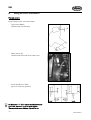
1
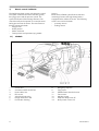
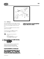
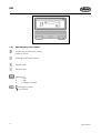
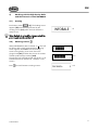
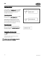
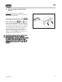
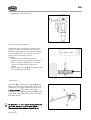
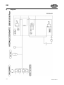
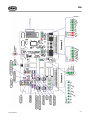
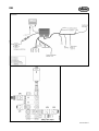
Operation manual
INFOBALE
+
-
G0203GPR(3)EN
© Kverneland Geldrop BV, Nuenenseweg 165, NL-5667KP Geldrop
DE:
Dieses Buch und alle darin enthaltenen einzelnen Angaben und Abbildungen sind Urheberrechtlich geschützt.
Jede Verwertung ausserhalb der Grenzen des Urheberrechts ist ohne ausdrückliche, schriftliche Zustimmung des
Herausgebers unzulässig. Das gilt insbesondere für Vervielfältigungen aller Art, Übersetzungen, Mikroverfilmungen, einschliesslich Mikro- und Makrofiche, und die Einspeicherung und/oder Verarbeitung in elektronischen und
optischen Systemen, einschliesslich aller Video und CD-Systeme.
DK:
Med forbehold af vor ret. Ingen del af denne bog må gengives, gemmes i database eller andet søgesystem, ej heller publiceres
på nogen måde eller i nogen form, hverken elektronisk, mekanisk, optisk, på tryk, fotokopi, mikrofilm (incl. mikro- eller
makrofiche) eller på anden vis – herunder alle video og CD systemer – uden forudgående skriftlig tilladelse fra udgiveren.
EN:
All rights reserved. No part of this book may be reproduced, stored in a data base or retrieval system, or published, in any
form or in any way, electronically, mechanically, optically, by print, photoprint, microfilm (including micro and macro fiche), or
any other means, including all video and CD systems, without prior written permission from the publisher.
ES:
El presente manual se acoge al amparo del Derecho de la Propiedad Intelectual. Salvo permisión escrita quedan
reservados todos los derechos inherentes en especial los de reimpresión, de traducción, de reproducción en
forma fotomecánica ó en cualquier otra forma, incluídos microfilmes, micro- y macrofichas así como el almacenamiento y procesamiento en sistemas electrónicos y ópticos, incluídos todos sistemas de video y CD, aún cuando
no se utilice más que parcialmente texto o figura.
FR:
La propriété littéraire de ce manuel est protégée et les droits en découlant sont réservés. L'utilisation, même partielle, du texte es des illustrations n'est admissible qu'avec la permission écrite de l'auteur,en particulier la reproduction, la traduction, la restitution par des systèmes photomécaniques ou tous autres, y compris les microfilms, les
micro- et macrofiches ainsi que la mise en mémoire et le traitement dans des installations électroniques et optiques,
y compris les systèmes vidéo et CD.
IT:
Tutti i diritti di autore riservati. L'utilizzazione, anche parziale, del presente manuale, in particolare la ristampa, la
traduzione, la riproduzione mediante microfilm, micro- e macroschede, come pure la memorizzazione e/o elaborazione tramite impianti elettronici, videosistemi e sistemi CD compresi, è ammessa solo se autorizata preventivamente dall'autore per iscritto.
NL:
Niets uit dit boek mag worden verveelvoudigd, opgeslagen in een, al dan niet, geautomatiseerd gegevensbestand of openbaar gemaakt; in enige vorm of op enige wijze hetzij electronisch, mechanisch, optisch, door fotokopieën, microverfilming (inclusief micro- en macrofiche), opnamen, of enig andere manier, inclusief alle video en
CD-systemen, zonder voorafgaande schriftelijke toestemming van de uitgever.
This operation manual contains the instructions for the use and the maintenance of the
electronic INFOBALE system. It is a complementary manual to the other baler operation
manuals of the LB 8100 and LB 12100. The object of this manual is to help you achieve the
benefits you expected when buying this baler.
The output of your machine will depend to a large extent in your way of using it and
maintaining it. It is very important to read this manual carefully before using the baler and to
keep it handy. In this way, you will avoid accidents, respect the warranty conditions and
always have a functional machine in perfect working order.
Respect the security advice in this operation manual and on the security stickers on the baler as
well as the general security and accidental prescriptions.
Table of contents:
page
Electronic control INFOBALE
1 – Electronic control Infobale.........................................................................................................................................2
1.1 Infobale.............................................................................................................................................................................2
1.2 Building in....... ..........................................................................................................................................................3
1.3 Operating keys and switches .........................................................................................................................................4
2 – Working with the high density baler and the electronic control Infobale ....................................................................5
2.1 Starting..............................................................................................................................................................................5
2.2 Working screens.......................................................................................................................................................5
2.3 Function menu ..................................................................................................................................................................6
3 – Baling process.....................................................................................................................................................................7
3.1 Setting the hydraulic density pressure............................................................................................................................7
3.2 Monitoring the plunger load ....... ............................................................................................................................8
4 – Fault messages ....................................................................................................................................................................9
5 – Electric emergency control density pressure............................................................................................................... 11
6 - Stopping baling ................................................................................................................................................................ 12
6.1 Unhitching the baler ..................................................................................................................................................... 12
6.2 Preparing for winter....... ........................................................................................................................................ 12
7 - Factory functions .............................................................................................................................................................. 13
8 – Setting the sensors and indicators .................................................................................................................................. 16
9 – Wiring and hydraulics diagram ..................................................................................................................................... 18
10 – Trouble shooting table .................................................................................................................................................. 20
11 – EC Certificate of conformity........................................................................................................................................ 21
Danger:
When you see this safety alert symbol and heading be alert to the danger of injury of death of men and animals!
Attention:
When you see this heading, be alert to the possibility of damage to equipment, crop, buildings, etc., but to
financial and/or juridical problems (warranty, product liability) as well!
A remark, proposal, advise to facilitate a job.
©Kverneland
1
1)
Electric control “Infobale”
The high density baler comes with electronic control.
This system controls and monitors the bale growth,
the tying process and the pressure control. The
system also features fault message functions. The
control box allows the operator to control the entire
baling process from the tractor. The main functions
that are monitored include:
- Plunger load
- Knifes position
- Packer overload
- Twine position and operation tying needle
1.1)
Infobale
1
2
3
4
5
6
7
Control box
Connection cable control box
Power cable 12V
PTO sensor
Valve block hydraulics
Plunger load sensor ML
Fans knotter cleaning
2
Sensors
Because the Infobale system features extensive
monitoring functions, the high density baler is
equipped with a number of sensors. The following
sensors are used on the baler:
- proximity sensors
- analog sensors
8
9
10
11
12
13
14
Emergency stop fans
Tying sensor
Needle frame shear bolt sensor
Twine sensor
Machine casing
Feed fork safety sensor FF
Knife position sensor OC
© Kverneland
EN
1.2)
Building in
Mount the INFOBALE control box (1) in the tractor
cab within reach and view of the operator. The box
has an on/off switch (2), a display and function
keys.
INFOBALE control system must be switched off and
the power cables must be pulled out.
The machine casing (3) on the baler has a balergeared control system.
Connect the power cable (4) to the battery.
Connect cable (5) to the control box.
Fuses
- -
Monitoring and control box F1:
1x2A
Machine control F2:
1 x 15 A (outputs and processors)
1 x 30 A (fans and 12V output)
When connecting the power cable to the battery,
note the correct polarity.
(+): brown cable
(-): blue cable
Never connect the cable to the cigarette lighter
(interference risk), always directly to the
interference-free power source (check the
functioning of the fuses on the power cables).
Keep cables away from hot and moving parts.
When unhitching the machine from the tractor, the
connectors of cables (4) and (5) must always be
pulled out and placed in the special holder. When
the machine is not used for an extended period, the
© Kverneland
3
EN
1.3)
Operating keys and switches
Function key, to next function, setting
position or screen.
Switching on/off Opticut (option)
Increase value
Decrease value
Main switch
I
= ON
0
= OFF
II
= Emergency control
Emergency control
No function
4
© Kverneland
EN
2)
Working with the high density baler
and the electronic control INFOBALE
2.1)
Starting
Put the main switch
to (I). The loading screen
appears (d1) automatically followed by the
working screen (w1), after which the machine is
ready for use.
d1
When the baler is not used for a longer period, the
power supply must be switched off.
2.2)
Working screens
When INFOBALE has been switched on, a short self
test follows after which automatically the working
screen appears. INFOBALE has two working
screens during baling. One screen shows the
plunger load (w1) and the other shows the number
of bales produced (trip counter) (w2).
The plunger load is displayed with the aid of 2 x 14
indication blocks (a maximum of 14 blocks on the
screen).
Press
to switch between working screens.
© Kverneland
or
w1
w2
5
EN
2.3)
Function menu
The function menu can be called up from the
working screen by simultaneously pressing
. Settings can be changed using the
keys.
and
and
= select or increase value.
= select or decrease value.
F1
(F1) F+ menu
Confirm the selected F+ menu.
F2
(F2) Trip bale counter.
Reset by simultaneously pressing
and
.
(F3) Total number of bales produced by the
machine. Not resettable.
(F4) Display contrast
Adjust the displayed contrast(35 – 99%)
(F5) Sound level
Adjust the sound level(0 – 100%)
(F6) Language settings
Available settings are: EN, NL, FR, DE, ES, IT.
F3
F4
F5
(F7) Fan
Knotter cleaning using fans (option) can be
switched on or off.
F6
(F8) Knotter cleaning
Knotter cleaning using a compressor (option)
can be switched on or off.
F7
(F9) Automatic oil lubricating system
The automatic oil lubricating system (option)
can be switched on or off.
F8
(F10) Automatic grease lubricating system
The automatic grease lubricating system
(option) can be switched on or off.
F9
(F11) Automatic knife cleaning
Automatic knife cleaning system (only
applicable for Opticut) can be switched on or
off.
(F12) Last F+ screen
or 0.
F10
F11
simultaneously = set value to default setting
= scroll key —> to next screen
F12
Pressing this key also confirms the setting of the
current screen before the next screen appears.
6
© Kverneland
EN
3)
Baling process
Caution: it is vital to let the machine run at nominal
speed during use. Only then can flawless operation
of the various functions be guaranteed.
The forward speed (choice of gear) must always be
adapted to the swath width. To achieve maximum
bale density, the separate wads in the bale must not
be thicker than 5 cm. If large quantities regularly
cause feeder overload, then the forward speed must
be reduced.
Adapt the forward speed to the number of
compression strokes per bale. The working screen
showing the plunger strokes per bale is a good tool
here.
Examples:
Bale growth per plunger stroke can be estimated on
the basis of the compression time per bale. the
plunger makes 45 compression strokes/min at
1000 rpm. Allow for turning at the headland and
stopping in the field.
3.1)
bale length(in cm)
80
120
160
180
200
220
240
250
260
no strokes per bale
16
24
32
36
40
44
48
50
52
Setting the hydraulic density
pressure
The operator has to set the hydraulic density
pressure.
= increase pressure
= decrease pressure
Adapt the density pressure to the conditions
(material, crop humidity, swath shape, twine
strength etc.).
Caution: The maximum density pressure is 170 bar.
Let the pto run so the hydraulic pressure can be
read from the pressure gauge.
© Kverneland
7
EN
3.2)
Monitoring the plunger load
The plunger load is indicated permanently. The
black bars show the load. The number of bars (=
total length), 28 in total, varies with the load on the
plunger.
or
Caution: For all working conditions the limit is the
flywheel safety or a broken twine when the tied
bale leaves the bale chamber. In that case the
pressure must be reduced by pressing
8
.
© Kverneland
EN
4)
Fault messages
Caution: When the various warning screens appear
on the display, an acoustic signal sounds and
certain lights start blinking. The warnings appear
every three to four seconds.
Overload plunger alarm and density pressure
control:
Dependent on the crop and the crop flow the
plunger load may increase until the
mechanical overload device is activated. The
ML sensor measures the plunger load up to a
certain maximum value. When indicator light
(1) starts blinking, the plunger load is too
high. Information on display: « RAM
OVERLOAD » . When the alarm appears, the
density pressure drops by 5 bar and the
baling chamber opens step-by-step! Note: the
preset pressure is not automatically restored!
If the alarm keeps appearing, the density
pressure must be reduced by ± 10 bar
and/or the forward speed must be reduced.
Twine alarm:
A twine problem is indicated by a flashing light (2;
see page 10). Information on display: « NO TWINE
». That means one or more twines are not fed to the
knotter. Trace and remedy the cause.
No pto:
If display « PTO !!! » appears, it is an indication the
machine is driven but there is no signal of the pto
sensor. Check pto sensor (see also page 16).
© Kverneland
9
EN
Needle shear bolt alarm:
A twine problem is indicated by a flashing light (2).
If the display shows: « NEEDLE BOLT » , the needle
shear bolt has failed so the twine can no longer be
tied. Replace the shear bolt. Start tying once
manually to reset the alarm.
Alarm packer overload:
Packer overload is indicated by a flashing light (3).
The display shows: « FEED OVERLOAD » .
Stop the baler and reduce the pto rpm, so the
overload clutch can engage again. If this clutch
does not engage anymore, then stop the pto and
remove the cause of the problem. If the clutch slips,
the forward speed must be adapted.
Communication alarm:
There is a communication problem between the
baler control box and the control box in the tractor.
Information on display: « COMMUNICATION » .
Consult your dealer.
Switching off one of the above alarms:
Press
once to remove the information from the
display.
In all case the lights remain blinking until the
problem has been solved.
Caution: In the event of a recurring message the
cause must be traced and remedied.
10
© Kverneland
EN
5) Electric emergency control density
pressure
In the event of an electronic problem, the
INFOBALE control system still offers a possibility to
control the density pressure.
Put the main switch under the control box
in
position (II). The density pressure can be increased
with the emergency switch
on the
side
until the required setting has been reached on the
pressure gauge. Repeat this procedure regularly
(every 30 sec, depending on frequency of reading
the manometre). Now the operator can read the
desired pressure from the pressure gauge. The
maximum density pressure is set by rotating the
handwheel of the proportional valve on the
hydraulic valve block (V5)! This procedure must
NEVER be performed during work!
Caution: The emergency density pressure control
makes it possible to continue work despite
electronic problems. It remains important to remedy
the problem quickly. Quick and proper baler
operation requires that the machine runs with the
INFOBALE control system with the main switch in
position (I).
© Kverneland
11
EN
6)
Stopping baling
Stop picking up and let the machine run for a few
moments to transport the crop that is still in the
chamber. Then switch off the pto.
Act as follows to eject the last bale:
- start a tying process;
- take the pressure from the density pressure circuit:
on the
keep the machine running and press
control box;
- switch off the pto after some time;
- disconnect the power supply to the electronic
control system INFOBALE.
Caution: Before picking up an already compressed
bale, the twine must be removed and the bale wads
must be laid loosely in the swath to prevent pick-up
and packer overload.
6.1)
Unhitching the baler
When unhitching the baler from the tractor, the
cables of the INFOBALE control system must be
disconnected.
6.2)
Preparing for winter
- Dismount the control box and store it in a dry
place.
- Do not use high-pressure water or steam cleaners
within the area of the electronic control panel and
the electric connections.
When you observe the above rules, you will have a
fully operable machine at the start of the next
harvest season. Consult your dealer if you have any
questions. Before taking into use again, all
adjustment activities described in the user manual
must be carried out.
12
© Kverneland
EN
7)
Factory Functions
and
calls up the Factory Functions. This menu is intended for engineers. The
Simultaneously pressing
—
factory functions include two menus > test and settings.
Caution: When calling up Factory Functions, stop the baler and simultaneously press
Exit the Factory Functions by repeatedly pressing
dependent on the screen that had been called up.
© Kverneland
and
.
. That may have to be done a number of times
•
Start F- menu
•
Menu selection test / settings
•
Outputs
•
•
Test menu selected
V1 selection valve build density
pressure or circulate (on/off)
•
•
On (+ key) = activate
Off (-- key) = deactivate
•
V2 selection valve knife control
(on/off)
•
•
On (+ key) = activate
Off(— key) = deactivate
•
V3 selection valve knife control
(on/off)
•
•
On (+ key) = activate
Off (— key) = deactivate
•
V5 proportional valve
density pressure setting
•
•
+ key = increase
— key = decrease
•
Electric fans for knotter cleaning •
•
•
Clockwise
Off
Counter clockwise
•
Pneumatic knotter cleaning
•
•
On (+ key) = activate
Off (— key) = deactivate
•
Automatic oil lubrication
•
•
On (+ key) = activate
Off (— key) = deactivate
•
Automatic grease lubrication
•
•
On (+ key) = activate
Off (— key) = deactivate
•
Inputs
13
EN
14
•
ML = Machine Load sensor
•
Current value
•
Twine sensor
•
Current value
•
PTO test
•
•
0 = no signal
1 = signal
•
FF (packer) test
•
•
0 = no signal
1 = signal
•
Bind = tying needle
•
•
0 = no signal
1 = signal
•
Opticut
•
•
0 = no signal
1 = signal
•
Needle frame shear bolt
•
Keyboard test screen for keys
and LEDs
•
•
•
0 = no signal
1 = signal
Press a key —> The key number
appears on the display and the
LED will go out. Press a key twice
to return to the basic screen.
•
Start F- menu
•
Menu selection test / settings
•
Settings - menu is selected
•
On-board computer software
version
•
V1.07 19 – 07 – 00 = software
version
•
Implement software version
•
V1.07 19 – 07 – 00 = software
version
•
PIN code
•
Not available
•
ML- offset
•
•
287 = current (counts) of sensor
170 = setting for ML sensor if no
load)
© Kverneland
EN
•
ML- max. setting
•
•
•
•
© Kverneland
500 = growth bar on display is
fully black
nb >600 = ML alarm
Total number of bales produced
on the machine
Last screen Settings
15
EN
8)
Setting the sensors and indicators
Proximity sensors
The proximity sensors trace metal objects.
- Tying sensor (BIND)
(situated at the needle frame)
- Packer sensor (FF)
(situated at left hand side of the intake rotor)
- Power take-off sensor (PTO)
(top view of the main gearbox)
Set dimension (A) of the sensors must be between 2
and 6 mm, measured up to the metal surface.
The connected sensor indicator light will be on.
16
© Kverneland
EN
- Needle frame shear bolt sensor
- Sensor plunger overload (ML)
The read-out value of the plunger overload safety
must be 170 when unloaded. The value can be
checked in the settings menu of the factory functions.
If the unloaded value is not 170 (± 5), the “zero
setting” must be corrected as follows.
Procedure:
- Open the screen ML MIN of the factory
functions settings menu. The value on the left is
the current value of the ML sensor. It must be
170 when unloaded (on the right on the
screen).
- With the aid of the nuts (4) of the ML sensor the
sensor position can be shifted.
- Twine sensor
The sensor (5) is activated by a magnet (6) on the
twine arm. In the event of a twine failure the arm is
pulled down by a spring, followed by the message
« twine problem » on the display. The spacing
between the sensor (5) and the magnet (6) must be
between 20 and 25 mm with the lever on the stop in
the bottom position.
Set dimension (A) of the sensors must be between 2
and 6 mm, measured up to the metal surface.
The connected sensor indicator light will be on.
© Kverneland
17
EN
9)
18
Diagrams
© Kverneland
EN
© Kverneland
19
EN
20
© Kverneland
EN
10)
Trouble shooting table
Caution: the electronic control system operates reliably. Most malfunctions are caused by incorrect connections.
The central operating panel on the machine may only be opened by people with sufficient expertise. Make sure
no dirt gets into the opened central operating panel.
MALFUNCTION
CAUSE
- no message on the monitoring and - no power supply to the control
control box
system
SOLUTION
- switch on the device
- check the system power
- check fuses
- alarm « no connection » appears on - control box not equipped with
- switch off and back on at proper
the display
"HIGH DENSITY BALER" computer power supply
program
- check power supply of central
control panel
- check connection between control
box and machine box
- recurring alarm
© Kverneland
- internal control system problem
- consult your dealer
- sensor set incorrectly
- check sensor setting
21
EN
11)
CE Certificate of Conformity
CE CERTIFICATE OF CONFORMITY
in accordance with the EU-Directive 89/392/EEC
We,
Kverneland Geldrop BV,
Nuenenseweg 165,
NL-5667KP Geldrop
declare under our sole responsibility that the product: Big square baler, type LB to which this declaration relates
corresponds to the relevant basic safety and health requirements of the Directives 89/392/EEC (amended with
91/368/EEC, 93/44/EEC and 93/68/EEC) and 98/37/EC.
For the relevant implementation of the safety and health requirements mentioned in the Directives, the following
standards have been respected:
EN292-2, EN294, EN704
Geldrop, 20 April 2002
Casper Böhme
General Manager
"KVERNELAND GELDROP BV" manufacturers of farm machinery reserve the right to change design and/or
specifications without notice. This does not include an obligation to make changes to machines previously
supplied.
22
© Kverneland
KVERNELAND GELDROP BV
Nuenenseweg 165
Postbus 9
NL 5660 AA Geldrop
The Netherlands
Tel. +31 40 289 33 00
Fax +31 40 285 32 15
Prod. Series No. (PSN): 510212, 510211
Gültig ab Produkt Identifikations Nr. (PIN):
À partir du no. d’identité du produit (PIN):
Effective from product identification no. (PIN):
Vanaf product identificatie nr. (PIN):
218055
216050
printed 2002-05-31
© Kverneland
Vicon is a brand of the Kverneland group
G0203GPR(3)EN