1
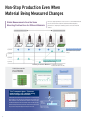
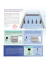
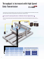
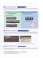
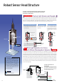
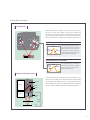
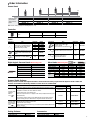
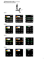
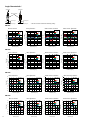
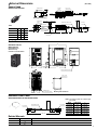
ZW Series Confocal Fiber Displacement Sensor
The 24x24x64-mm Sensor Head
redefines the meaning of ultra-compact
» Robust Sensor Head Structure
» Ultra-compact and Ultra-lightweight
» Stable Measurements for Any Material
Omron’s Confocal Fiber Displacement Sensor
that Goes Beyond Triangulation Concepts
with a New Principle
In machine control, displacement sensors are
indispensable for non-contact measurements
of heights, thickness and other dimensions.
However, integrating them into the system
poses challenges such as the size of the
sensor, its weight and noise immunity.
The ZW Series confocal displacement sensor
solves these problems in ways not possible
using traditional triangulation sensors.
They provide the compact size, light
weight, immunity to electrical/magnetic
noise, and other features to make them
ideal for solving installation problems.
OMRON’s new confocal principle provides the
measurement resolution that is needed for
precise control. The ZW Series solves the
problems that are inevitable with laser
triangulation, such as deviations between
different materials and inclination tolerance.
A Wider Selection of Models with the Same Head Size
ZW-S20
ZW-S07
Stable
Measurements
for Thin Glass
ZW-S30
Expanded
Communications
Standard-feature
EtherCAT
ZW-S40
Measuring
center distance
P.10
Standard-feature EtherNet/IP ™
(mm)
40
30
20
High precision
2
7
0
-EtherCAT® is a registered trademark and patented technology, licensed by Beckhoff Automation GmbH, Germany.
-EtherNet/IP™ are the trademarks of ODVA.
Omron’s White Light Confocal Principal Offers
Three Unique Benefits
Save Machine Space and
Reduce Settling Time
The slim design measures only 24 X 24 mm. It weighs
only 105 g. This incredibly compact size could not be
achieved with traditional triangulation sensors. Any
object can be measured with the Sensor mounted
perpendicularly to them to save even more space.
P.4
Stable Measurements for
Any Material
te
ss
stra
Sub
Gla
ror
Mir
S
SU
ic
am
cer
ite
Wh
Measure different materials or color, there is no need
to reposition the sensor. A wide angle characteristic
of ±8° enables high-resolution measurement of the
position even for large objects with mirror-like
surfaces without being affected by warping.
P.6
Electrical Noise and Heat
are Not a Problem
No electronic
parts.
The sensor head design maintains reliable operation
in installations where electrical noise exists.
Devices in close proximity to the sensor head or
cable, will not be affected by noise or heat due to the
sensor head's advanced design.
P.8
3
Ultra-Compact and Ultra-Lightweight
Utilize Narrow Spaces in Machines
The 24 x 24-mm Sensor Head fits easily into essentially any machine.
Triangulation sensor
87% less
Volume & Weight
compared to previous
models*
64mm
*In-house comparisons.
24mm
24mm
Mounting area Reduced to 1/7*
*In-house comparison.
With traditional triangulation sensors, it was necessary to use either diffuse reflection
or regular reflection depending on the material. However, the confocal principle used
for the ZW Series eliminates the need to change the Sensor installation even if the
material changes.
Traditional Triangulation Model
Diffuse-reflective
Sensor
Regular-reflective
Sensor
ZW Series
The Sensor can be installed
perpendicular to the object
regardless of the material.
Height Control of a Dispenser Nozzle
Substrate
Glass
Substrate
Glass
Sensor Installation in a Row with
No Interference
Mutual interference or space restrictions often prevent the
installation of traditional triangulation sensors. The compact
ZW Series sensor heads allow you to install more sensors, in
a row or pattern.
Non-contact Flatness Inspection of HDD Cases
4
Minimum pitch
24 mm
Low Inertia Delivers Smooth and Fast Response
When mounting the measurement sensor to an actuator, the sensor head has a
significant influence. The heavier the sensor, the longer the settling time, which
results in slower production. With the ZW Series sensors, the settling time is
significantly reduced because it weighs 0.23 lbs allowing measurements to start
sooner creating greater tme savings for faster production speeds.
ZW Series
Time
Degree of
oscillation
Moved.
Degree of
oscillation
Stopped.
Traditional Triangulation Model
Time
Bonding Height Inspection
Easy and Flexible Cable Installation
The Controller connects to the Sensor
Head with a 2-mm-diameter Flexible
Fiber Cable. The cable has cleared a
bending test consisting of 2,000,000*
repetitions for reliable application on
moving parts.
*Cable was tested with OMRON’s bending
test consisting of 2,000,000 bends to a 70-mm
bending radius and 1,000,000 bends to a
20-mm bending radius.
Ultrathin
Cable
Cable diameter: 2 mm
Minimum bending radius: 20 mm
R
Installation in a Cable Carrier
Cable Extendable to 32 meters
An Extension Fiber Cable can be used between the Sensor Head and Controller to extend the distance to up to 32 m. Attach the Sensor
Head to a moving part and place the Controller in the control panel or other convenient location to achieve a flexible system design.
Standard Fiber Cable
0.3 or 2 m
Extension Fiber Cable
30 m max.
Connecting adapter
Sensor Head
Controller
5
Non-Stop Production Even When
Material Being Measured Changes
Stable Measurements from the Same
Mounting Position Even for Different Materials
No need to adjust parameters or tune sensor for each individual material
to be measured. Achieve stable measurements without adjusting
parameters or changing the mounting positions even as the material
changes.
Regular-reflective workpiece
Mirror
Diffuse-reflective workpiece
Glass
SUS
White ceramic
Substrate
Using ZW-S20 sensor head
Linearity
±2 µm or less
Stable measurements for any material
to ±2 µm
±3 µm or less
±4 µm or less
Traditional Triangulation Model
±5 µm or less
Large discrepancy between materials.
Linearity for Various Materials
Stable Measurements
across Boundaries
between Materials
(Comparisons for Sensor with a
measuring center distance of 20 mm.)
ZW Series
Traditional Triangulation Model
(ZW-S20 results)
Substrate
Measurement Area
Thin Transparent glass - Thickness
measurement is not a problem using
the ZW compact sensor heads
To make stable measurements on glass, the light waveform received from the front
and back surfaces of the glass must be separated. When using compact sensor
heads, the influence of lens aberration makes it difficult to achieve such separations when measuring these surfaces. Even with its compact size that saves space,
the ZW-S07 stably measures transparent surface displacement on glass as thin as
75 µm, a feat not easily achieved by previous compact sensor heads.
(All measurement graphs represent typical examples.)
6
100
1099
Received light amount
2098 3097 4096
0.2
0.1
0
Glass
thickness:
75 µm min.*
*ZW-S07:75 µm min.
ZW-S20: 200 µm min.
P1
P2
-0.1
-0.2
Received Waveform for ZW Series Sensor
P1
P2
Reduce Machine Setup Costs with
Superior Angle Characteristics
Using traditional triangulation sensors, the angle of the sensor
head has to be adjusted when measuring mirror-like surfaces. This
angle adjustment compromises not only the sensor performance,
but also casues downtime for setup.
If several sensors are used in an application such as height control
during glass conveyance, the angle of every sensor must be
adjusted with high precision. This again contributes to downtime
for setup.
The confocal ZW Series offers a superior angle characteristic,
which enables high resolution measurements without strict angle
adjustment. This results in cost reduction for setup and downtime,
not to mention the reduction of space or costs in the design of an
adjustable jig.
* This is not a guaranteed value.
Refer to Characteristic Data (P17)
for typical examples.
Angle
characteristic
±8° *
Height Control during Glass Conveyance
Traditional Triangulation Model
ZW Series
With triangulation, even if the angle is adjusted with high precision during the setup of
ZW Series Sensors operate on the confocal principle, so high-resolution measure-
the Sensor, stable measurement results are difficult to obtain when the measurement
ments are possible regardless of inclination and warping of the measurement
object is warped or inclined.
object.
30
+4° Measurement is
not possible.
+2°
20
+2°
10
+1.5°
10
+1.5°
0°
0
-1.5°
-10
-2°
-4° Measurement is
not possible.
-20
-30
Error (µm)
Error (µm)
30
20
+4°
0°
0
-1.5°
-10
-2°
-20
-4°
-30
-1
-0.5
0
0.5
1
-1
Distance (mm)
No Discrepancy in the Measurement Point
Superior angle characteristics are not the only advantage of a confocal
principle.With a traditional triangulation, the measurement position and
spot size vary with the height. This means there are times when the
position cannot be measured with high resolution due to warping and
inclination. With the confocal principle used in the ZW Series, the measurement point remains the same at any position in the measuring range so
that precise measurements can always be made.
-0.5
0
0.5
Distance (mm)
Traditional Triangulation Model
Measurement position Varies
with the Height
1
(Sensor: ZW-S20)
ZW Series
No Discrepancy in the
Measurement Position
7
Advanced Sensor Head Structure
No Noise
Reduced Work for
EMC Countermeasures
Not Affected by Noise
To ensure high-resolution measurements with Standard sensors, countermeasures
must be implemented to protect the sensor from the electromagnetic noise that is
emitted by any nearby electrical devices. The ZW Series Sensor Heads, however, contain no electronic parts to enable stable measurements even if they are near power
lines or electrical equipment. Also, the Fiber Cable that connects the Sensor Head to
the Controller can be placed near power lines and other cables that emit noise without
affecting operation.
Traditional Triangulation Model
Changes in Measurement
Values Caused by Noise
ZW Series
Measurements are not affected by
noise and remain stable.
Measurement
value
Measurement
value
Noise
waveform
Noise
waveform
Time
Time
No Noise Emission
No electronic parts are used in the ZW Series Sensor Heads or Fiber Cables, so
they give off no electromagnetic noise. You can therefore use them reliably
together with other devices sensitive to electrical noise.
Traditional Triangulation Model
Electronic parts
ZW Series
Fiber Cable
Substrate Height Inspection
No electronic parts.
Electromagnetic noise is emitted from the
sensor and from cables.
8
No Noise Emitted.
No Heat Generation
Reduced Work in Thermal Design
In high-resolution machine control, the heat generated by a sensor head can adversely
affect nearby equipment and cause the error to increase. The ZW Series Sensor Heads,
however, generate no heat and therefore do not affect nearby equipment. You can also install many Sensor Heads side by side and still be sure of reliable operation.
Traditional Triangulation Model
ZW Series
+2℃
+0℃
Change in Temperature after 1.5 Hours of Operation
No Electronic Parts
No electronic
parts in the
Sensor Head.
An LED is used in
place of a laser for
the light source to
eliminate the need
for safety measures.
Reduced Maintenance Costs
Displacement sensors are often installed in moving applications and other installations
that are subject to vibration. It is important that they can withstand this type of requirement. The ZW Series Sensor Heads are designed for this type of environment, they
have no electronic parts or PCB's that a standard triangulation sensor contains. The reduction of parts to lenses and Fiber Cables reduces the maintenance requirements, and
the LED light source also eliminates the standard safety measures required for lasers.
Traditional Triangulation Model
Electric circuits
and the light
source are
contained in the
Controller.
ZW Series
Laser diode
Electronic parts
Special set of
lenses that
require no drive
system.
No electronic
parts.
9
Throughput is Increased with High Speed
Data Transmission
The EtherCAT high-speed open network was optimized for machine control. The ZW Series Sensors are the first OMRON Displacement Sensors with EtherCAT to provide a highly
efficient design for high-precision machine control applications that use measurement results to control machine operation.
Increase Processing Precision in Machine Control Applications
EtherCAT can be used to network to servo drives or encoder input slaves to quickly transfer the position coordinates and ZW displacement to the machine controller.
The accuracy of height measurements with XY position data provides the added maintenance benefit to use the inspection application to help isolate errors and perform
trend analysis.
NJ-Series Machine
Automation Controller
Servomotor/
Servo Drive
10
Servo/encoder X
Servo/encoder Y
Results of Linking with the Position Coordinates
Measurement point
Measurement result Z
Point 1
Z1
X1
Y1
Machine Controls
Inspection Applications
Point 2
Z2
X2
Y2
Increased
processing precision
Isolation of errors
Point 3
Z3
X3
Y3
No need for
constant-speed
control
Trend management
for specific positions
High-speed Digital Output
Shorter Machine Cycle Times
When comparing EtherCAT over previous communications outputs through Ethernet or RS-232C, the response period for measurement commands was both
inconsistent and slow, making them unsuitable for realtime control. With EtherCAT, a constant period as short as 500 µs enables continuous digital (serial) outputs
allowing measurement values to be mapped at high speed.
Previous Serial Output
EtherCAT Output for ZW Series Sensor
The outputs for command inputs required
4 ms or longer and were not consistent.
Measurement values are output continuously at
a fixed period that is as short as 500 µs.
Measurement Commands
Communications
Processing
Communications
Output
Output
Output
Output
4 ms or longer
Communications
Processing
Communications
Continuous outputs at a period
Output
that is as short as
500 µs .
4 ms or longer
Communications
Processing
Communications
8 Times Faster
Than OMRON’s
Previous Models
Output
4 ms or longer
Tracing Machine Movement
Fewer Steps in System Commissioning
You can develop, test, and adjust devices that are connected via EtherCAT with just one Support Software package. Omron’s Sysmac Studio software allows you to
creatively design your controls. You can see the entire range from sensing to motion control to reduce the number of steps required to commission the system or
to aid in troubleshooting. There are also plenty of offline features to debug signal control programming. You can also simulate machine operation before actual
application onsite.
Data Trace
Debugging Control Programming
Note: Sysmac Studio version 1.05 or higher is required for these software interface features described.
Long-distance Wiring: 100 m
Flexible Wiring for Machines
You can use EtherCAT to connect slaves that are up to 100 m apart. With digital communications, the influence of ambient noise does not cause errors. This solves
the previous problems with analog output methods, such as the inability to support long-distance transmissions and noise countermeasures, and enables reliable
installation in previously difficult large-scale machines.
-Sysmac is a trademark or registered trademark of OMRON Corporation in Japan and other countries for OMRON factory automation products.
-Windows is registered trademarks of Microsoft Corporation in the USA and other countries.
-Other company names and product names in this document are the trademarks or registered trademarks of their respective companies.
-Microsoft product screen shot(s) reprinted with permission from Microsoft Corporation.
11
Simultaneous Calculations and
Instant Multi-Point Measurements
EtherCAT communications provide both high speed and time-consistent performance so that integrated controls for Sensors and other
slaves can be achieved in realtime. Even for multipoint measurements for Displacement Sensor applications, the following advantages
are provided.
Reduced Wiring: Only Two Cables
Plug and Play
With previous parallel I/O, manual wiring was required for dozens of points, and it was necessary to
take sufficient caution to avoid sources of noise. This required extensive time to use many
Displacement Sensors in a row. With EtherCAT, all you have to do is connect two lines for each
Controller.
Previously
Dozens
of
Wires
Servomotor/
Servo Drive
ZW Series
Only
Two
Cables
NJ-Series Machine
Automation Controller
One Software
Fewer Steps in System Design
You can set up all of the slaves that are connected via EtherCAT with Measurement Utility of the Automation Software Sysmac Studio.
Even when you combine multiple Sensors, you can copy setup data to effectively integrate setup work or you can easily program
calculations between the Sensors.
Sysmac Studio
Sensor 1
Increased efficiency in
copying setups
Sensor 2
Efficient Setup of Measurement
Conditions for Many Sensors
12
Easy Programming of Thickness Calculations
Synchronous Measurements
Fewer Thickness Errors due
to Vibration
The highly precise synchronization performance of EtherCAT reduces the time error in measurements between
different Sensors to 1 µs or less. Synchronous measurement is useful when measurements must be made with more
than one Sensor at the same time, such as measurements from both sides of a sheet or inclination control of a
substrate.
Previously Not Synchronized
The thickness
includes error.
Vibration that occurs during
measurements taken at different
time causes the output thickness
to be larger than normal.
ZW
Measurements taken
at different times.
Synchronized with
EtherCAT
Thickness
Thickness measurements of
sheets for lithium ion batteries.
T he correc t thick ness is
me asured wi thout being
influenced by vibration.
Synchronized
Note: Differences between the Sensors may cause the measurement time to vary by up to 24 ppm.
Continuous Measurements of Sheets without Position Offset
When Sensors are installed in a row to continuously log sheet height, nonsynchronous measurements
can cause offsets in the lateral measurement positions. With synchronous measurements using
EtherCAT, you can continuously log sheet height with all of the Sensors at the same lateral position.
Previously: Not Synchronized
ZW: Synchronized with EtherCAT
13
Robust Sensor Head Structure
To achieve a compact Sensor Head and high-resolution measurements,
the ZW Series uses a white light confocal principle to detect objects.
This principle is described below.
Confocal principle
Confocal Light Emission and Reception
Based on the confocal principle, the emitted light and received light are positioned along the same axis. Light is
received only when it is focused on the measurement object, allowing the height to be calculated. Unlike triangulation, the received light waveform is not disrupted by the material type or inclination of the measurement
object. The received light waveform is always stable, which enables high-resolution measurements.
Object Located at Focal Point
The reflected light is focused at the same point as
the emitted light.The reflected light becomes the
received light signal.
Object Not Located
at Focal Point
Reflected light is not received due
to the point of focus for point of
light emission.
Inclination and
Differences in Materials
Even if the measurement object is inclined or contains different materials,
the reflected light will be focused at
the light emission point as long as the
measurement object is at the focal
point.
Light
emission
point
Focal point
White light
Reflected light
Focal
point
Focal point
The height is calculated from the position
at which the reflected light was received.
White
The OCFL module contains a special lens set developed by OMRON that changes the focal point
for each color (i.e., wavelength) of white
light.The spot diameter is the same at any position within the measuring range. It does not
change the way it does for a triangulation.
High-precision lens manufacturing technology
has allowed us to achieve a lens structure that
is extremely small and that also does not require a drive mechanism.
Focal point
Emitted light
Confocal point
OCFL Module
Light
emission
point
=
=
Light emission point
Light is not
received.
White Light Separation into Colors
with Different Wavelengths at Emission
Patent Pending
The white light from the LED is focused at different points for each color (i.e., wavelength) due to a special set of lenses in the
OCFL module in the Sensor Head. As a result, only the color of light that is focused on the measurement object is returned,
allowing the distance from the Sensor Head to the measurement object to be calculated based on the color of the reflected light.
The Sensor Head contains the special set of lenses that separates white light into different colors and the Controller contains the
white LED light source, and the spectroscope and processor that convert the color of the reflected light to a distance. There is
no need for a lens drive mechanism or electronic parts in the Sensor Head, even though they were considered to be standard for
other manufacturer's confocal models. This achieves a compact design with greater immunity to noise than triangulation models
and or competitor models. The ZW controller contains a white LED light source, the spectroscope and processor that analyzes
the color of the reflected light.
The height is detected based on
the wavelength.
Fiber Cable
White light
High
Pass
White LED
light source
Low
100.300
100.250
ZERO
ENABLE
Spectroscope
OCFL Module
The reflected light of the wavelength that was focused
on the surface of the measurement object passes
through the fiber and the spectroscope in the Controller converts the wavelength to a distance.
Receiver
Distance
USB
*OCFL : Omron Chromatic Focus Lens
Processor
RS232C
PARALLEL
14
ROM
HEAD
NEAR
Colors are separated
along the height direction.
FAR
Amount of
received light
Problems with Previous Models
Triangulation
Triangulation measures the height of an object based on the position of
the spot on a receiver (CCD or CMOS). The peak, center of gravity, and
other features are calculated from the received light waveform to reduce
error, but in principle, the received waveform is offset or disrupted due to
differences in materials or inclination. This results in measurement error.
Laser diode
FAR
NEAR
Reciever
Light Reception for Different Materials
Emission lens
Receiver
Reception lens
Ideal
waveform
Waveform
disrupted
NEAR
FAR
Different materials have different reflection factors. This disrupts the waveform
that is received on the receiver.The peak in
the waveform or the center of gravity are
used to calculate the height, but error will
remain in the measurement results.
Light Reception for Inclination
Receiver
Waveform
disrupted
NEAR
Normal Confocal Principle
Laser diode
Processor
Pinhole
Ideal
waveform
If the measurement object is inclined, the
received waveform is offset or disrupted
due to the effects of aberration. This results in measurement error.
FAR
In a normal confocal model, a stage and lens are driven vertically to change
the focal point. This requires a more complex structure, and the large number
of parts interferes with downsizing. The use of a laser beam increases the
chances of interference, and the received light waveform can be disrupted by
the surface conditions within the small spot on the measurement object.
Receiver
Drive processor
Lens
+
Lens drive
circuit
Move the stage
and lens vertically.
Stage
15
System Configuration
EtherCAT connections
Basic Configuration
Controller
ZW-CE1
Other
EtherCAT
Slaves
S
d
Sensor H
Head
ZW-S
EtherCAT Cable
(RJ45/RJ45)
Calibration ROM
(included with Sensor Head)
EtherCAT Cable
(Select the cable that matches
the Slave's connector.)
EtherCAT Cable
(RJ45/RJ45)
EtherCAT Cable
(RJ45/RJ45)
EtherCAT Master
Setting Software
Ethernet *2
/USB
Sysmac Studio
Standard Edition
SYSMAC-SE20
v 1.05 or later required
Machine Automation Controller
NJ series
Analog, EtherNet/IP, Ethernet, RS-232C and Parallel connections
Communications capabilities depends on model type
Basic Configuration
S
Sensor
H
Head
d
ZW-S
Calibration ROM
(included with Sensor Head)
Analog, RS-232C and Parallel
Switching
Hubs
Control PLC
EtherNet/IP *2, *3, Ethernet *2
Setting Software
or
Sysmac Studio
Measurement Sensor Edition
SYSMAC-ME00 L
Smart Monitor ZW
ZW-SW101
*1 Controllers with binary outputs are also available (ZW-C10T/-C15T).
Please contact your OMRON sales representative for details.
*2 Prepare commercially available Ethernet cable satisfying the following requirements:
• Category 5e or higher, 30 m or less
• RJ45 connector (8-pin modular jack)
• For direct connection: Select cross cable.
• For connection through an industrial switching hub: Select straight cable.
*3 Ethernet/IP is only on ZW-CE10T/CE15T Controllers.
16
Order Information
Sensor Head
40
30
20
7
0
Measuring range
Spot diameter
Static resolution
7±0.3mm
18 µm dia.
0.25µm
ZW-S07 m
Model
30±3mm
60 µm dia.
0.25µm
20±1mm
40 µm dia.
0.25µm
ZW-S20 m
40±6mm
80 µm dia.
0.25µm
ZW-S30 m
ZW-S40 m
Note: When ordering, specify the cable length (0.3 m, 2 m).
Controller
Appearance
Power supply
DC24V
Cable
Appearance
Item
Sensor Head - Controller Extension
Fiber Cable (flexible cable) (Fiber
Adapter ZW-XFC provided)
Fiber Adapter (between Sensor Head
pre-wired cable and Extension Fiber
Cable)
Parallel cable for ZW-CE1 T 32-pole*
(included with Controller ZW-CE1 T)
Output type
EtherCAT Model
ZW-CE10T
ZW-C10T
PNP
ZW-CE15T
ZW-C15T
Cable length
2m
5m
10m
20m
30m
Model
ZW-XF02R
ZW-XF05R
ZW-XF10R
ZW-XF20R
ZW-XF30R
—
ZW-XFC
2m
ZW-XCP2E
Vacuum Heads
Appearance
Specification
ZW-SR20
ZW-S20
Right Angle WD
& Vacuum Heads
NEW Coming 20mm
Soon
Same
Same
Measuring
range
20.mm
Appearance
Specification
ZW-SR20
m
µm (average 4096)
Static resolution Same – Print 0.25µm 0.02
WD
20mm
Linearity
± 1.6µm (mirror)
± 1.2µm (mirror)
20.mm
Measuring range
Spot size
Same
40µm
0.25µm (average
Static
Sensorresolution
size
24 x 33 x 88mm
24 x 24 x4096)
64mm
± 1.2µm (mirror)
Linearity
40µm
Spot size
Sensor size
Ethernet Model
NPN
24 x 24 x 64mm
Appearance
Item
Cable length
Model
2m
ZW-XCP2
RS-232C Cable for personal computer
2m
ZW-XRS2
RS-232C Cable for PLC/
programmable terminal
2m
ZW-XPT2
Parallel cable for ZW-C1 T
52-pole required
(NOT included with Controller ZW-C10
Micro Heads
Model
T)
ZW-SP12
ZW-SP20
ZW-SP40
20±0.7mm
40±2mm
Static resolution
0.01
µm – Print 0.25
µm – Print 0.25
µm – Print 0.25
Model *1
ZW-SP12
mµm 0.02
ZW-SP20
mµm 0.05
ZW-SP40
mµm
*2
Linearity
0.5µmm
m
1.0µmm
m
±2.5
m
Measuring
range
12±±0.3
20±±0.7
40
±2µ
mm
GAP
60µm
100µ
300µ
Staticseparation
resolutionability*3
µm
0.25µmm˜
0.25
0.25µmm˜
˜
Temperature
1.1µ
1.6µ
2.6µ
Linearity characteristic
±0.5m/°C
µm
±1.0m/°C
µm
±2.5m/°C
µm
GAP separation
60µ
100µ
300µ
Spot
Nearability
25µm
m˜
35µm˜
55µm˜
size
20µ
m
30µ
m
50µ
m
Center
Temperature characteristic
1.1µ
m/°C
1.6µ
m/°C
2.6µ
m/°C
25µm
35µm
55µm
Far
Spot
Near
*1
size
20µm
30µm
50µm
Center
*2
*3
25µm
35µm
55µm
Far
Micro
Heads
Soon
Measuring
range NEW Coming
12±0.3mm
Sysmac Studio Software
Please purchase a DVD and required number of licenses the first time you purchase the Sysmac Studio. DVDs and
licenses are available individually. Software License does not include DVD.
Product name
Sysmac Studio
Standard
Edition
*2
Ver.1.
Sysmac Studio
Measurement
Sensor Edition
Ver.1.
Specifications
The Sysmac Studio provides an integrated development environment to set up,
program, debug, and maintain NJ-series Controllers and other Machine
Automation Controllers, as well as EtherCAT slaves.
Sysmac Studio runs on the following OS.
Windows XP (Service Pack 3 or higher, 32-bit version)/Vista(32-bit version)/7(32bit/64-bit version)
This software provides functions of the Measurement Sensor Edition. Refer to
Sysmac Catalog (P072) for details such as supported models and functions.
Sysmac Studio Measurement Sensor Edition is a limited license that provides
selected functions required for ZW-series
Displacement Sensor settings.
Because this product is a license only, you need the Sysmac Standard Edition DVD
media to install it.
Model
Standards
DVD
SYSMAC-SE200D
—
1 license*1
—
SYSMAC-SE201L
—
1 license
—
SYSMAC-ME001L
—
3 license
—
SYSMAC-ME003L
—
Number of licenses
Media
—
(Media only)
*1 Multi licenses are available for the Sysmac Studio (3, 10, 30, or 50 licenses).
*2 ZW-series is supported by Sysmac Studio version 1.05 or higher.
Setting Software
Item
Smart Monitor ZW
Model
ZW-SW101
Accessories
Item
Fiber Connector Cleaner
Model
ZW-XCL
17
Recommended EtherCAT Communications Cables
Use Straight STP (shielded twisted-pair) cable of category 5 or higher with double shielding (braiding and aluminum foil
tape) for EtherCAT.
Cable with Connectors
Wire Gauge and Number of Pairs: AWG22, 2-pair Cable
Item
Appearance
Recommended manufacturer
Cable with Connectors on Both Ends
(RJ45/RJ45)
OMRON
Cable with Connectors on Both Ends
(M12/RJ45)
OMRON
Cable with Connectors on Both Ends
(M12 L/RJ45)
OMRON
Cable length(m)
0.3
0.5
1
2
5
10
0.3
0.5
1
2
5
10
0.3
0.5
1
2
5
10
Note: The cable length 0.3, 0.5, 1, 2, 3, 5, 10 and 15m are available. For details, refer to Cat.No.G019.
Model
XS5W-T421-AMD-K
XS5W-T421-BMD-K
XS5W-T421-CMD-K
XS5W-T421-DMD-K
XS5W-T421-GMD-K
XS5W-T421-JMD-K
XS5W-T421-AMC-K
XS5W-T421-BMC-K
XS5W-T421-CMC-K
XS5W-T421-DMC-K
XS5W-T421-GMC-K
XS5W-T421-JMC-K
XS5W-T422-AMC-K
XS5W-T422-BMC-K
XS5W-T422-CMC-K
XS5W-T422-DMC-K
XS5W-T422-GMC-K
XS5W-T422-JMC-K
Cables / Connectors
Wire Gauge and Number of Pairs: AWG24, 4-pair Cable
Item
Appearance
Cables
RJ45 Connectors
* We recommend you to use above cable and connector together.
Wire Gauge and Number of Pairs: AWG22, 2-pair Cable
Item
Appearance
Cables
RJ45 Assembly Connector
Recommended manufacturer
Hitachi Cable, Ltd.
Kuramo Electric Co.
SWCC Showa Cable Systems Co.
Panduit Corporation
Model
NETSTAR-C5E SAB 0.5 × 4P *
KETH-SB *
FAE-5004 *
MPS588-C *
Recommended manufacturer
Kuramo Electric Co.
Nihon Electric Wire&Cable Co.,Ltd.
Model
KETH-PSB-OMR *
PNET/B *
OMRON
XS6G-T421-1 *
* We recommend you to use above cable and connector together.
Note: Connect both ends of cable shielded wires to the connector hoods.
Industrial Switching Hubs for Ethernet
Appearance
Number of ports
Failure detection
Current consumption
3
None
0.22A
5
None
Supported
0.22A
Model
W4S1-03B
W4S1-05B
W4S1-05C
Note: Industrial switching hubs cannot be used for EtherCAT.
EtherCAT Junction Slaves
Appearance
Number of ports
Power supply voltage
3
Current consumption
Model
0.08A
GX-JC03
0.17A
GX-JC06
20.4 to 28.8 VDC
(24 VDC -15 to 20%)
6
Note: 1. Do not connect EtherCAT junction slave with OMRON position control unit, Model CJ1W-NC 81/ 82
2. EtherCAT junction slaves cannot be used for EtherNet/IPTM and Ethernet connectivity.
18
Specifications
Sensor Head
Item
Measuring center distance
Measuring range
Static resolution *1
Linearity *2
Spot diameter *3
Near
Center
Far
Measuring cycle
Operating ambient illumination
Ambient temperature range
Ambient humidity range
Degree of protection
Vibration resistance (destructive)
Shock resistance (destructive)
Temperature characteristic *4
Materials
Fiber cable length
Fiber cable minimum bending radius
Insulation resistance (Calibration ROM)
Dielectric strength (Calibration ROM)
Weight
Accessories included with sensor head
ZW-S07
ZW-S20
ZW-S30
7mm
20 mm
30mm
±0.3mm
±1 mm
±3mm
0.25 µm
0.25 µm
0.25 µm
±0.8 µm
±1.2 µm
±4.5 µm
20 µm dia.
45 µm dia.
70 µm dia.
18 µm dia.
40 µm dia.
60 µm dia.
20 µm dia.
45 µm dia.
70 µm dia.
500 µs to 10 ms
Illumination on object surface 10,000 lx or less: incandescent light
Operating: 0 to 50°C, Storage: −15 to 60°C
(with no icing or condensation)
Operating and storage: 35% to 85%
(with no condensation)
IP40 (IEC60529)
10 to 150 Hz, 0.35 mm single amplitude, 80 min each in X, Y, and Z directions
150 m/s2 3 times each in six directions (up/down, left/right, forward/backward)
0.6 µm/ °C
1.5 µm/ °C
2.8 µm/ °C
Case:
aluminum die-cast
Fiber cable sheat: PVC
Calibration ROM: PC
0.3 m, 2 m (Flex-resistant cable)
20 mm
Between case and all terminals: 20 MΩ (by 250 V megger)
Between case and all terminals: 1,000 VAC, 50/60 Hz, 1 min
Approx. 105 g (Chassis, fiber cable total)
Instruction sheet, Fixing screw (M2) for Calibration ROM, Precautions for correct use
ZW-S40
40 mm
±6 mm
0.25 µm
±7.0 µm
90 µm dia.
80 µm dia
90 µm dia
4.8 µm/ °C
*1. Capacity value when Omron standard mirror surface target is measured at the measurement center distance as the average of 4,096 times.
*2. Material setting for the Omron standard mirror surface target: Error from an ideal straight line when measuring on mirror surface.
The reference values for linearity when targets to measure other than the above are as in the table below.
Item
Glass
SUS BA
White ceramic
ZW-S07
±1.0 µm
±1.2 µm
±1.6 µm
ZW-S20
±1.2 µm
±1.4 µm
±1.7 µm
ZW-S30
±4.5 µm
±5.5 µm
±6.4 µm
ZW-S40
±7.0 µm
±8.5 µm
±9.5 µm
*3. Capacity value defined by 1/e2 (13.5%) of the center optical intensity in the measured area.
*4. Temperature characteristic at the measurement center distance when fastened with an aluminum jig between the Sensor Head and the target and the Sensor Head
and the controller are set in the same temperature environment.
Sysmac Studio Software (For ZW-CE1 T type only)
System Requirements
Item
Operating system (OS) *1 *2
CPU
Main memory
Recommended video memory /
video card for using 3D motion trace
Hard disk
Display
Disk drive
Communications ports
Supported languages
Requirement
Windows XP (Service Pack 3 or higher, 32-bit version)/Vista(32-bit version)/7(32-bit/64-bit version)
Windows computers with Celeron 540 (1.8 GHz) or faster CPU.
Core i5 M520 (2.4 GHz) or equivalent or faster recommended
2 GB min.
Video memory: 512 MB min.
Video card: Either of the following video cards:
• NVIDIAR GeForceR 200 Series or higher
• ATI RadeonHD5000 Series or higher
At least 1.6 GB of available space
XGA 1024 × 768, 16 million colors.
WXGA 1280 × 800 min. recommended
DVD-ROM drive
USB port corresponded to USB 2.0, or Ethernet port *3
Japanese, English, German, French, Italian, Spanish, simplified Chinese, traditional Chinese, Korean
*1. Sysmac Studio Operating System Precaution: System requirements and hard disk space may vary with the system environment.
*2. The following restrictions apply when Sysmac Studio is used with Microsoft Windows Vista or Windows 7.
Some Help files cannot be accessed.
The Help files can be accessed if the Help program distributed by Microsoft for Windows (WinHlp32.exe) is installed. Refer to the Microsoft
homepage listed below or contact Microsoft for details on installing the file. (The download page is automatically displayed if the Help files are
opened while the user is connected to the Internet.)
http://support.microsoft.com/kb/917607/en-us
*3. Refer to the hardware manual for your Controller for hardware connection methods and cables to connect the computer and Controller.
Setting Software Smart Monitor ZW-SW101
System Requirements
Item
Operating System(OS)
CPU
Main memory
Hard disk
Display
Supported languages
Communication port
Condition
Windows 7 (32 or 64-bit version)
Windows XP (Service Pack3 or more, 32-bit version)
Intel Pentium III, 850 MHz or more (2 GHz or more is recommended.)
1 GB or more
50 MB or more
1024 × 768 dots or more, 16 million colors or more
Japanese/English
Ethernet port
19
20
Controller
Controller
Item
Item
Input/Output type
Input/Outputof
type
Number
connected Sensor Heads
Sensor
compatibility
Number ofHead
connected
Sensor Heads
Light
for measurement
Sensor source
Head compatibility
Main display
Segment
Light source for measurement
display
Sub-display
Segment display Main display
ZW-C19T
ZW-CE10T
ZW-CE15T
ZW-CE15T
ZW-C10T PNP
ZW-C15T
NPN
NPN
PNP
NPN
PNP
1 per
Controller
Available
1 per Controller
White LED
Available
11-segment red display, 6 digits
White LED
11-segment green display, 6 digits
11-segment red display, 6 digits
HIGH (orange), PASS (green), LOW (orange), STABILITY (green), ZERO (green),
Sub-display
11-segment green display, 6 digits
Status indicators
ENABLE (green), THRESHOLD-H (orange), THRESHOLD-L (orange), RUN (green)
LED
display Status indicators
LED display
HIGH (orange), PASS (green), LOW (orange), STABILITY (green), ZERO (green), ENABLE (green), THRESHOLD-H (orange), THRESHOLD-L
L/A IN(Link Activity IN)(green), L/O OUT(Link Activity OUT)(green), ECAT RUN(green), ECAT
(orange), RUN (green)
EtherCAT indicators
ERR(red)
EtherCAT indicators
L/A IN(Link Activity IN)(green), L/O OUT(Link Activity OUT)(green), N/A
Ethernet
100BASE-TX, 10BASE-T, No-protocol Communications (TCP/UDP), EtherNet/IP TM
ECAT RUN(green), ECAT ERR(red)
EtherCAT
EtherCAT-specific protocol 100BASE-TX
External
Ethernet
100BASE-TX, 10BASE-T, No-protocol Communications (TCP/UDP)
RS-232C
115,200 bps max.
interface
Ethernet I/P
Yes
N/A
Analog
Analog voltage output (OUT1V) -10 V to +10 V, output impedance: 100 Ω
EtherCAT
EtherCAT-specific protocol 100BASE-TX
N/A
output
RS-232C
115,200
bps max.
terminal
Analog current
output
(OUT1A) 4 mA to 20 mA, maximum load resistance: 300Ω
block
Analog
voltage output (OUT1V)
Analog
-10 V to +10 V, output impedance: 100 Ω
20-pole
(Specifications are the same as 32-pole
output
extension
connectors for ZW-CE19T models)
Judgment output
output
system
Analog current output (OUT1A)
4 mA to 20 mA, Transistor
maximum load
resistance:
300 Ω
connector
terminal
(HIGH1/PASS1/LOW1)
Output voltage: 21.6 to 30 VDC
block
BUSY output (BUSY1)
Load current: 50 mA or less
Judgment output (HIGH1/PASS1/
32-pole
Transistor output system
Residual voltage when turning ON: 1.2 V or less
ALARM output
(ALARM1)
LOW1)
extension
Output voltage: 21.6 to 30 VDC
connector
Load current: 50Leakage
mA or lessvoltage when turning OFF: 0.1 mA or les
ENABLE output
(ENABLE)
ALARM output (ALARM1)
Residual voltage when turning ON: 1.2 V or less
External
LED OFF input (LED OFF1)
DC
input system
Leakage voltage when turning OFF: 0.1 mA or less
ENABLE output (ENABLE)
interface
Input voltage: 24 VDC ⋅10% (21.6 to 26.4 VDC)
ZERO RESET input (ZERO)
Input current: 7 mA Typ. (24 VDC)
LED OFF input (LED TIMING
OFF1)
DC input system.
output (TIMING1)
Input voltage: 24
VDC 10% (21.6 to 26.4
VDC)
Voltage/Current
when
turning ON: 19 V/3 mA or more
32-pole
ZERO
RESET input (ZERO)
RESET output (RESET1)
Input current: 7 Voltage/Current
mA Typ. (24 VDC) when turning OFF:5 V/1 mA or less
extension
Voltage/Current when turning ON: 19 V/3 mA or more
TIMING
output (TIMING1)
system
connector
Voltage/CurrentTransistor
when turningoutput
OFF:5 V/1
mA or less
Output voltage: 21.6 to 30 VDC
RESET output (RESET1)
Selected bank output
Load current: 50 mA or less
(BANK_OUT Transistor
1 to 3) output system
Bank
Selected bank output
52-pole
Residual voltage when turning ON:
1.2 V or(Bank
lessinput/outputs specifications are
(BANK_OUT 1 to 3)
Output voltage: Leakage
21.6 to 30 VDC
extension
voltage when turning OFF:
0.1 mAtheorsame
lessas 32-pole connectors for
connector ZW-CE19T models)
Load current: 50 mA or less
Bank
DC
input
system
Residual voltage
when
turning
ON: 1.2 V or less
21.6
VDC
Leakage voltageInput
when voltage:
turning OFF:
0.1 to
mA26
or less
Selected bank input
Input current: 7 mA Typ. (24 VDC)
Selected bank input (BANK_SEL DC
1 toinput
3) system.
For Binary I/O specifications please refer to ZW-C1_T manual
Voltage/Current
when turning ON: 19 V/3 mA or more
(BANK_SEL 1 to 3)
Input voltage: 21.6
to 24VDC
Input current: 7 Voltage/Current
mA Typ. (24 VDC) when turning OFF:5Binary
V/1 mA or less
Voltage/Current when turning ON: 19 V/3 mA or more
Exposure time
Auto/Manual
Voltage/Current when turning OFF:5 V/1 mA or less
Measuring cycle
500 μs to 10 ms
Main functions
Exposure time
Auto/Manual
Material setting
Standard/Mirror/Diffusion surfaces
Measuring cycle
500 µs to 10 ms
Measurement Item
Height/Thickness/Calculation
Material setting
Standard/Mirror/Diffusion surfaces
Filtering
Median/Average/Differentiation/High pass/Low pass/Band pass
Measurement
Item
Height/Thickness/CalculationScaling/Different holds/Zero reset/Logging for a measured value
Outputs
Main functions
Filtering
Median/Average/Differentiation/High
pass/Low
pass/Band pass value/Analog output voltage or current value/Judgment result/
Measured
value/Threshold
Display
Resolution/Exposure
time
Outputs
Scaling/Different holds/Zero reset/Logging
for a measured
value
Max. 8 banks
Number of configurable banks
Display
Measured value/Threshold value/Analog
output voltage or current value/Judgment result/ Resolution/Exposure time
Task
Multi-task (up to 4 tasks per bank)
Number
of process
configurable banks
Max. 8 banks
Save/Initialization/Display measurement information/Communication settings/Sensor Head
TaskSystem
process
Multi-task (up to 4 tasks per bank)
calibration/Key-lock/Trigger-key input
System
Save/Initialization/Display measurement information/Communication settings/Sensor Head calibration/Key-lock/Trigger-key input
Power supply voltage
21.6 to 26.4 VDC (including ripple)
Ratings
Power supply voltage
21.6 to 26.4 VDC (including ripple)
Current consumption
600 mA max.
Ratings
Current
consumption
600 mA max.
500 case:
mA max.
Insulation
resistance
Across all lead wires and controller
20 MΩ(by 250 V megger)
Insulation
resistance
Across all lead wires and controller
case:
MΩ(by
250and
V megger)
Dialectic
strength
Across
all 20
lead
wires
controller case: 1,000 VAC, 50/60 Hz, 1 min.
Dialectic
strength
Across all lead wires and controller
case: 1,000 VAC, 50/60 Hz, 1 min.
Degree
of protection
IP20(IEC60529)
Vibration
resistance (destructive)
10 to 55 Hz, 0.35-mm single amplitude, 50 min each in X, Y, and Z directions
Environmental
Degree
of protection
IP20(IEC60529)
times
inand
sixZdirections
Shock resistance (destructive)
m/s2,503min
10 to 55 Hz, 0.35-mm single 150
amplitude,
eacheach
in X, Y,
directions (up/down, left/right, forward/backward)
EnvironmentalVibration resistance (destructive)
Operating:
0 to 40°C
Shock
resistance
(destructive)
150 m/s2, 3 times each in six directions (up/down,
left/right, forward/backward)
Ambient
temperature
Storage:-15 to 60°C (with no icing or condensation)
Ambient temperature
Operating: 0 to 40ºC, Storage:-15 to 60ºC (with no icing or condensation)
Ambient humidity
Operating and storage: 35% to 85% (with no condensation)
Ambient humidity
Operating and storage: 35º to 85º (with no condensation)
D-type grounding (Grounding resistance of 100 Ω or less)
Grounding
Grounding
D-type grounding (GroundingNote:
resistance
100 Ω or less) Note:
For ofconventional
ClassForDconventional
groundingClass D grounding
Materials
Case: PC
Materials
Case: PC
Weight
Approx. 750 g (main unit only),
Approx. 750
150 gg(Parallel
Weight
Approx.
(main Cable)
unit only), Approx. 150 g (Parallel Cable)
ZW-XCP2E
Accessories
included
with controller
Instruction
sheet,Member
registration
sheet,
Accessories included
with controller
Instruction sheet, Member registration
sheet,
Parallel cable ZW-XCP2E
included
with Parallel
ZW-CE1_Tcable
controller
only
Note: Controllers with binary outputs are also available (ZW-C10T/-C15T). Please contact your OMRON sales representative for details.
ZW-CE19T
ZW-CE10T
ZW Series EtherCAT Communications Specifications
Item
Communications standard
Physical layer
Connectors
20
Communications media
Communications distance
Process data
Mailbox (CoE)
Distributed clock
LED display
Specification
IEC61158 Type12
100BASE-TX(IEEE802.3)
RJ45 × 2
ECAT IN: EtherCAT input
ECAT OUT: EtherCAT output
Category 5 or higher (cable with double, aluminum tape and braided shielding) is recommended.
Distance between nodes: 100 m max.
Variable PDO mapping
Emergency messages, SDO requests, SDO responses, and SDO information
Synchronization in DC mode.
L/A IN (Link/Activity IN) × 1, AL/A OUT (Link/Activity OUT) × 1, AECAT RUN × 1, AECAT ERR × 1
Characteristic data (typical examples)
Linearity Characteristic by Materials
Measuring center
distance 0
ZW-S07
Material setting: Mirror surface
Material setting: Normal
Mirror
SUS BA
Glass
White ceramic
2
1
0
-1
Material setting: Diffusion surface
5
Mirror
SUS BA
Glass
4
3
2
Error [µm]
4
3
Error [µm]
5
1
0
-1
2
1
0
-1
-2
-2
-2
-3
-3
-3
-4
-4
-4
-5
-0.3
-5
-0.2
-0.1
0
0.1
0.2
Distance [mm]
0.3
White ceramic
4
3
Error [µm]
5
-0.3
-0.2
-0.1
0
0.1
0.2
Distance [mm]
-5
-0.3
0.3
-0.2
-0.1
0
0.1
0.2
Distance [mm]
0.3
ZW-S20
Material setting: Normal
8
6
6
2
0
-2
4
2
0
-2
-4
-6
-8
-8
-10
-1 -0.8 -0.6 -0.4 -0.2
0
0.2 0.4 0.6 0.8
0
-2
-4
-6
-8
-10
1
6
2
-6
White ceramic
8
4
-4
Material setting: Diffusion surface
10
Mirror
SUS BA
Glass
8
Error [µm]
Error [µm]
4
Material setting: Mirror surface
10
Mirror
SUS BA
Glass
White ceramic
Error [µm]
10
-1 -0.8 -0.6 -0.4 -0.2
Distance [mm]
0
0.2 0.4 0.6 0.8
1
-10
-1 -0.8 -0.6 -0.4 -0.2
Distance [mm]
0
0.2 0.4 0.6 0.8
1
Distance [mm]
ZW-S30
Material setting: Normal
Mirror
SUS BA
Glass
White ceramic
16
12
8
12
4
0
-4
Material setting: Diffusion surface
20
Mirror
SUS BA
Glass
16
Error [µm]
Error [µm]
Material setting: Mirror surface
20
White ceramic
16
12
8
8
4
4
Error [µm]
20
0
-4
0
-4
-8
-8
-8
-12
-12
-12
-16
-16
-20
-20
-3 -2.5 -2 -1.5 -1 -0.5 0 0.5 1 1.5 2 2.5 3
Distance [mm]
-16
-20
-3 -2.5 -2 -1.5 -1 -0.5 0 0.5 1 1.5 2 2.5 3
Distance [mm]
-3 -2.5 -2 -1.5 -1 -0.5 0 0.5 1 1.5 2 2.5 3
Distance [mm]
ZW-S40
20
Error [µm]
15
10
Material setting: Normal
30
Mirror
SUS BA
Glass
White ceramic
25
20
15
5
0
-5
-10
Material setting: Mirror surface
30
Mirror
SUS BA
Glass
25
5
0
-5
-15
-20
10
5
0
-5
-10
-10
-20
-15
-20
-25
-25
-25
-30
-30
-30
-6 -5 -4 -3 -2 -1
0
1
2
Distance [mm]
3
4
5
6
White ceramic
15
10
-15
Material setting: Diffusion surface
20
Error [µm]
25
Error [µm]
30
-6 -5 -4 -3 -2 -1
0
1
2
Distance [mm]
3
4
5
6
-6 -5 -4 -3 -2 -1
0
1
2
3
4
5
6
Distance [mm]
21
Angle Characteristic *
α direction
β direction
Model nameplate
Slope angle +
Slope angle +
Slope angle −
Slope angle −
*The above show the results after executing scaling.
ZW-S07
3
1
0
-1
2
3
1
0
-1
-2
-0.15
0
0.15
-5
-0.3
0.3
Distance [mm]
3
2
1
0
0
0.15
2
1
0
-3
-4
-5
-0.3
0.3
Distance [mm]
Slope angle
+50°
0°
−50°
-2
-4
-0.15
β direction
-1
-3
-4
-5
-0.3
4
-2
-3
-4
5
-1
-2
-3
White ceramic
Slope angle
+50°
0°
−50°
4
Error [µm]
2
Slope angle
+8°
0°
−8°
4
Error [µm]
3
White ceramic α direction
5
Error [µm]
5
Slope angle
+8°
0°
−8°
4
Error [µm]
Mirror β direction
Mirror α direction
5
-0.15
0
0.15
-5
-0.3
0.3
Distance [mm]
-0.15
0
0.15
0.3
Distance [mm]
ZW-S20
Mirror β direction
4
2
Slope angle
+8°
0°
−8°
8
6
Error [µm]
6
0
-2
White ceramic α direction
10
4
2
6
0
-2
-4
-1
-0.5
0
-0.5
1
Distance [mm]
0
-1
-0.5
0
-0.5
0
-6
-8
-10
1
Distance [mm]
2
-4
-8
-10
4
-2
-6
-8
-10
6
-4
-6
-8
2
β direction
Slope angle
+50°
0°
−50°
8
-2
-4
-6
4
White ceramic
10
Slope angle
+50°
0°
−50°
8
Error [µm]
Slope angle
+8°
0°
−8°
8
Error [µm]
10
Error [µm]
Mirror α direction
10
-1
-0.5
0
-0.5
1
Distance [mm]
-10
-1
-0.5
0
-0.5
1
Distance [mm]
ZW-S30
Slope angle
+6°
0°
−6°
10
5
Slope angle
+6°
0°
−6°
15
Error [µm]
Error [µm]
15
White ceramic α direction
0
-5
20
10
5
Slope angle
+50°
0°
−50°
15
0
-5
White ceramic
20
10
5
0
-5
10
5
0
-5
-10
-10
-10
-10
-15
-15
-15
-15
-20
-20
-20
-3
-2
-1
0
1
Distance [mm]
2
3
-3
-2
-1
0
1
Distance [mm]
2
3
-3
-2
-1
0
1
Distance [mm]
2
-20
3
β direction
Slope angle
+50°
0°
−50°
15
Error [µm]
Mirror β direction
20
Error [µm]
Mirror α direction
20
-3
-2
-1
0
1
Distance [mm]
2
3
ZW-S40
Mirror β direction
0
-10
22
10
0
-20
-6
-4
-2
0
2
Distance [mm]
4
6
-30
White ceramic
30
Slope angle
+50°
0°
−50°
20
-10
-20
-30
Slope angle
+5°
0°
−5°
20
Error [µm]
Error [µm]
10
30
10
0
-10
-20
-6
-4
-2
0
2
Distance [mm]
4
6
-30
β direction
Slope angle
+50°
0°
−50°
20
Error [µm]
Slope angle
+5°
0°
−5°
20
White ceramic α direction
30
Error [µm]
Mirror α direction
30
10
0
-10
-20
-6
-4
-2
0
2
Distance [mm]
4
6
-30
-6
-4
-2
0
2
Distance [mm]
4
6
External Dimensions
(Unit: mm)
Sensor Head
ZW-S07/-S20/-S30/-S40
Standard surface
4±0.1
16±0.1
43± 0.1
Standard
surface
Four, M3
16±0.1
Standard
surface
4
16
16
43
Mounting hole dimensions
Measurement
center
Four, 3.5 dia.
(Mounting holes)
M (See note)
M (See note)
Connector
Standard fiber cable (2.0 dia.)
Measurement end
FAR
Note:
Model
L
M
X
ZW-S07
7
0.3
12
ZW-S20
20
1
11.8
ZW-S30
30
3
11.7
ZW-S40
40
6
11.7
12
X(See note)
24
24
Measurement
CENTER
(10 dia.)
Measurement end
NEAR
Caution
label
L (See note)
64
Lighting and
receiving axis
(40)
(50)
(42)
Controller
ZW-CE10T/-CE15T
128
ZW-C10T/-15T
External Reference
dimensions only.
Connector connection differs
124
34.9
40.8
6
(10.2)
72
(21.4)
127.5
DIN track attachment hook
40
Four, 4.5 dia.
70
70±0.1
14.5
43
Installation holes
Four, M4 depth 6.0 MAX
43±0.1
Mounting hole dimensions
Extension Fiber Cable
ZW-XF02R/-XF05R/-XF10R/-XF20R/-XF30R
Note: The following table lists cable lengths
per models.
FC connector
Fiber Cable (2.0 dia.)
FC connector
(10 dia.)
(42)
L (See note)
Related Manuals
(50)
(42)
Model
Cable length
L
ZW-XF02R
2m
2,000±20
ZW-XF05R
5m
5,000±50
ZW-XF10R
10 m
10,000±100
`ZW-XF20R
20 m
20,000±200
ZW-XF30R
30 m
30,000±300
Man.No.
Model number
Manual
Z332
ZW-CE1 T
Displacement Measurement Sensor ZW EtherCAT Model User’s Manual
Z332
ZW-C1 T
Displacement Measurement Sensor ZW Ethernet Model User's Manual
23
OMRON AUTOMATION AND SAFETY • THE AMERICAS HEADQUARTERS • Schaumburg, IL USA • 847.843.7900 • 800.556.6766 • www.omron247.com
OMRON CANADA, INC. • HEAD OFFICE
Toronto, ON, Canada • 416.286.6465 • 866.986.6766 • www.omron247.com
OMRON ARGENTINA • SALES OFFICE
Cono Sur • 54.11.4783.5300
OMRON ELECTRONICS DE MEXICO • HEAD OFFICE
México DF • 52.55.59.01.43.00 • 001.800.556.6766 • [email protected]
OMRON CHILE • SALES OFFICE
Santiago • 56.9.9917.3920
OMRON ELECTRONICS DE MEXICO • SALES OFFICE
Apodaca, N.L. • 52.81.11.56.99.20 • 001.800.556.6766 • [email protected]
OTHER OMRON LATIN AMERICA SALES
54.11.4783.5300
OMRON ELETRÔNICA DO BRASIL LTDA • HEAD OFFICE
São Paulo, SP, Brasil • 55.11.2101.6300 • www.omron.com.br
Omron Europe B.V. • Wegalaan 67-69, NL-2132 JD, Hoofddorp, The Netherlands. • Tel: +31 (0) 23 568 13 00 • Fax: +31 (0) 23 568 13 88 • www.industrial.omron.eu
Authorized Distributor:
Automation Control Systems
• Machine Automation Controllers (MAC) • Programmable Controllers (PLC)
• Operator interfaces (HMI) • Distributed I/O • Software
Drives & Motion Controls
• Servo & AC Drives • Motion Controllers & Encoders
Temperature & Process Controllers
• Single and Multi-loop Controllers
Sensors & Vision
• Proximity Sensors • Photoelectric Sensors • Fiber-Optic Sensors
• Amplified Photomicrosensors • Measurement Sensors
• Ultrasonic Sensors • Vision Sensors • RFID/Code Readers
Industrial Components
• Relays • Pushbuttons & Indicators • Limit and Basic Switches • Timers
• Counters • Metering Devices • Power Supplies
Safety
• Laser Scanners • Safety Mats • Edges and Bumpers
• Programmable Safety Controllers • Light Curtains • Safety Relays
• Safety Interlock Switches
Q65I-E-01
Note: Specifications are subject to change.
Printed on recycled paper.
© 2013 Omron Electronics LLC
Printed in U.S.A.