1
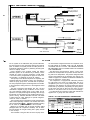
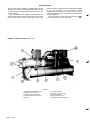
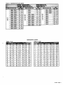
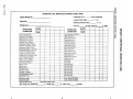
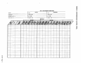
SINGLE COMPRESSOR CENTRlFUGAL CHlUERS
PEHIPHH 050,063,079,087,100,126
13600 Industrial Park Blvd.. P.O. Bow 1551, Minneapolis, MN 55440
OPERATION
OPERATOR RESPONSIBILITIES
It is important that the operator become familiar with the
equipment and the system before attempting to operate the
chiller.
In addition to reading this manual the operator should study
installation and operation bulletin IM 403 and the control
diagram furnished with the unit so that he understands the
starting, operating and shutdown sequences as well as the
safety shutdown modes.
When the McQuay Service technician performs the initial
startup of the chiller he will be available to answer any questions and to instruct in proper operating procedures.
It is recommended that the operator maintain an operating
log for each individual chiller unit. A suggested log sheet is
shown on pages 14 and 15 of this manual.
In addition, a separate maintenance log should be kept of
the periodic maintenance and servicing activities.
This McQuay centrifugal chiller represents a substantial
investment and deserves the attention and care normally
given to keep this equipment in good working order. If the
operator should encounter abnormal or unusual operating
conditions, it is recommended that a McQuay Service technician be consulted.
McQuay conducts training for centrifugal operators at its
factory Training Center several times a year. These sessions
are structured to provide basic classroom instruction and include hands-on operating and troubleshooting exercises. For
further information, contact your McQuay representative.
NOMENCLATURE
Each centrifugal chiller is assigned a set of identifying
numbers which are used to describe the unit features and
to identify each individual unit. These four-number groups
are stamped on each unit nameplate. A typical nameplate
is shown in Figure 1.
All inquiries pertaining to operating and servicing of this
unit should include all identification numbers.
Each of the individual components also have nameplates
to provide certain necessary information to the installer and
the operator.
The compressor nameplate identifies the compressor
model, style and serial numbers and includes the electrical
characteristics of the compressor motor. The CEO50 compressor nameplate also shows the oil pump electrical
characteristics.
The condenser and evaporator vessels have nameplates
stamped with the maximum working pressure of the vessel.
It should be noted that the vessel relief valve maximum settings coincide with the maximum refrigerant side vessel working pressure.
NOMENCLATURE CHANGE: The letter “H” has been added behind the first two digits of the model code to signify a hermetic
compressor motor. Models PE and PH are synonymous with PEH and PHH respectively.
MICROTECH CONTROL PANEL
The MicroTech Unit Controller is a microprocessor based control panel designed to initiate the step-by-step start functions
of its host centrifugal compressor unit, monitor and regulate
the compressor’s capacity, protect it, and sequence the compressor shutdown on temperature demand or in response to
a pre-set time.
For full information on the features, installation, operation
and problem analysis of the McQuay Microprocessor control
for Centrifugal chillers, see Installation and Operation Manual
IM 403.
FIGURE 1. MICROTECH CONTROL PANEL.
IM 307 I Page 3
CAPACITY CONTROL SYSTEM
The compressor capacity is controlled by the movement of
the inlet vanes, opening or closing to permit the correct quantity of refrigerant to enter the wheel or impeller. The vane
movement occurs in response to oil flow from the SA or SB
solenoid valve which, in turn, respond to a control module
signal. This oil flow activates a piston to rotate the vanes.
VANE OPERATION
The hydraulic system for the vane control operation consists
of a 4-way normally open solenoid valve. Oil under pressure
is directed by the 4-way valve to either or both sides of the
piston depending on whether the control signal is to load,
unload or hold.
To open the vanes (or load the compressor) solenoid “SA”
is de-energized and solenoid “SB” is energized, allowing oil
flow from port SA to one side of the piston to then drain
through port SB.
To close the vanes (unload compressor) valve SB is deenergized and valve SA is energized to move the piston and
vanes to unload position.
When both solenoid valves SA and SB are de-energized,
full oil pressure is directed to both sides of the piston through
ports SA and SB, thus the vanes are held in that position.
Refer to Figure 3 for solenoid action. Note that both solenoids
cannot be energized simultaneously.
VANE SPEED ADJUSTMENT
The vane speed at which the capacity control vanes open
or close is controlled by the rate of oil bleed-off from the vane
actuating piston. This bleed-off rate is adjustable by positioning the needle valves on SA and SB solenoid valves located
in the lube box.
Screwdriver openings in the left side of the lube box permit access. The upper opening accesses the SB needle valve
for adjusting the vane OPENING speed for loading the compressor (refer to Figure 2). Turn this screw clockwise to
decrease the vane opening speed and counterclockwise to
increase the opening speed.
The lower opening accesses the SA needle valve for adjusting the CLOSING speed for unloading the compressor.
The same adjustment applies. clockwise to decrease closing, counterclockwise to increase vane closing.
The vanes are factory set so that from fully closed to fully
open positioning of the vanes requires about 3 minutes and
about 1 minute from fully open to fully closed. (Exception:
CE126 settings are 9 minutes to open and 3 minutes to close).
FIGURE 2. LUBE BOX
METERING VALVES
The speed at which the capacity control vanes are opened
or closed can be adjusted to suit system operating requirements. Adjustable needle valves in the oil drain lines
are used to control the rate of bleed-off and consequently the
“vane speed”. These needle valves are part of the 4-way
solenoid valve assembly located in the compressor lube box
(Figure 2).
The valves are normally factory set so the vanes will move
from fully closed to fully open in approximately 3 minutes and
from fully open to fully closed in 1 minute (except CE126).
The speed should be slow enough to prevent over-controlling
and hunting.
FIGURE 3. VANE CONTROL SOLENOID OPERATION
-LEGEND- Oil Under Pressure
11,1 Oil Sump Pressure
COMPRESSOR
UNLOADER
CYLINDER
FLOATING PISTON
LINKED TO INLET VANES
-+ OPENS VANES
f- f - - C L O S E S V A N E S
FOUR WAY
SOLENOID VALVE
LOCATED IN
LUBE BOX
PISTON DRAIN
TO OIL
---_) PUMP
SUMP
SECTION “SE”
DE-ENERGIZED
SECTION “SA”
DE-ENERGIZED
ADJUSTABLE
NEEDLE VALVES
INTEGRAL
WITH FOUR WAY
SOLENOID VALVE
Page 4 / IM 307
FROM OIL
PUMP
DISCHARGE
-LEGEND- Oil Under Pressure
II Oil Sump Pressure
w
TO OIL
SECTION “SB”
ENERGIZED
SECTION “SA”
DE-ENERGIZED
DISCHARGE
SECTION “SE”
DE-ENERGIZED
SECTION “SA”
DRAIN FROM PISTON
OIL SYSTEM
The oil system for the PEH/PHH units provides lubrication
and heat removal for the compressor bearings and internal
parts. In addition, the system provides oil under pressure to
hydraulically operate the piston for positioning the inlet guide
vanes for capacity control.
Proper operation of the hydraulic system and bearing
lubrication system can be assured only if McQuay recommended oil is used. For proper oil selection, consult Table
1. Each unit is factory charged with the proper oil. Under normal operation, no additional oil should be needed.
The oil pump for the CEO50 compressor is completely selfcontained within the compressor housing. The assembly includes the pump, pump motor, oil heater and oil separator.
The oil is pumped through the oil discharge line to the oil filter
in the compressor casting and then to the refrigerant-cooled
oil cooler.
The other compressor sizes-CE063, 079, 087, 100 and
126-utilize a separate oil pump contained in its own oil reservoir. This assembly includes pump, motor, heater and oil
separator. Oil is pumped through the discharge line, through
the external oil cooler and then to the oil filter inside the compressor housing. Standard PEH/PHH 063-126 units utilize
a water-cooled oil cooler although an optional refrigerantcooled oil cooler is available.
The oil coolers serve to maintain the proper oil temperature
under normal operating conditions. The coolant flow control
valve should maintain 9O”F-100°F oil temperature leaving
the oil cooler for optimum operation of the oil system.
Bearings are supplied with oil through internally drilled
passages within the compressor assembly. The oil drains
from the bearings into the gear housing and is gravity returned
to the oil sump.
The oil heaters in the gear case and in the oil pump reser-
voir must remain energized whenever the compressor is off.
IN THE EVENT OF POWER LOSS TO THE HEATERS
ALLOWING THE OIL TO COOL, THE HEATERS SHOULD
BE ENERGIZED FOR 24 HOURS PRIOR TO STARTING
THE COMPRESSOR.
The MicroTech Microprocessor based control panel
monitors the oil temperature and prevents the unit from starting with low oil temperature. This prevents refrigerant laden
oil from being delivered to the bearings upon start-up. For
details see page 24 of Installation & Maintenance Bulletin IM
403 or the MicroTech control panel.
The compresssor is equipped with lubrication protection
for coast down in the event of a power failure. This is accomplished by the use of a spring loaded piston in models
CEO50 thru 100. When the oil pump is started, the piston is
forced back by oil pressure, compressing the spring and filling the piston cavity with oil. When the pump stops, the spring
pressure on the piston forces the oil out to the bearings.
In model CE126 the compressor coast down lubrication is
supplied from a gravity feed lube reservoir.
TABLE 1. OIL FOR CENTRIFUGAL COMPRESSORS
CEO87
CE100
CE126
11.0
12.0
SUNISO 4GS
SUNISO 5GS
TEXACO WF68
TEXACO WFI 00
SUNISO 5GS
TEXACO WF100
TEXACO REGAL 150
SHELL TURBO 150
IM 307 I Page 5
HOTGAS BYPASS
The PHH heat recovery chillers are equipped with a hot gas
bypass system used to feed discharge gas directly into the
evaporator when the system load falls below 10% of the compressor capacity.
Light load conditions are signaled by measurement of a
set percentage of RLA amps by the MicroTech control panel.
When the RLA drops to the hot gas setpoint the hot gas
bypass solenoid is energized leaving hot gas bypass available
for use. This introduction of hot gas provides a stable
refrigerant flow and keeps the machine from short cycling
under light load conditions. It also prevents surge during heat
recovery operation.
The factory setpoint for bringing on hot gas bypass is 40”
of RLA. See IM 403, page 33 for details.
FIGURE 5. PEH079 CHILLER (REAR VIEW)
LEGEND
1.
2.
3.
4.
5.
Page 6 / IM 307
Evaporator Pressure Relief Valve
Chilled Water Connections
Oil Cooler Water Connections
Condenser Pressure Relief Valve
Oil Cooler
6. Oil Pump Assembly
7. Discharge Line Check Valve
8. Lube (Control Box)
9. Motor Cooling Feed Line
10. Compressor Motor Terminal Box
MAINTENANCE
ROUTINE MAINTENANCE
LUBRICATION (See CAUTION)
After the system is once placed into operation, no other additional oil is required except in the event that repair work
becomes necessary to the oil pump or unless a large amount
of oil is lost from the system due to a leak.
If oil must be added with the system under pressure, use
a hand pump with its discharge line connected to the service valve at the bottom of the oil pump. (The CEO50 compressor with its internal oil pump is equipped with an oil service valve on the compressor).
CHANGING OIL FILTERS (See CAUTION)
CEO50 Compressors-If the unit is equipped with a suction
line service valve, close this valve and close the valve on the
motor cooling liquid line to isolate the compressor. Vent the
refrigerant pressure from the compressor. Remove the filter
cover and the old filter and install the new filter, open end
first. Replace the cover using a new gasket. Reopen the suction and liquid line valves.
If the unit is not equipped with a suction line service valve,
the unit will have to be pumped down in order to remove the
pressure in the compressor before removing the cover and
changing the filter. Refer to later section for pumpdown
procedure.
CEO63 and Larger Compressors-The oil filter in each of
these machines can be changed by simply isolating the filter
cavities. Close the oil discharge line service valve at the oil
pump (at the filter on CE126). Remove the filter cover; some
foaming may occur but the check valve should limit leakage
from other compressor cavaties. Remove the filter, replace
with new element and replace filter cover using new gasket.
Reopen valve in pump discharge line.
When the machine is operated again, the oil level should
be checked to determine if oil needs to be added to maintain proper operating level.
CAUTION
Improper servicing of the lubrication system, including
the addition of excessive or incorrect oil, substitute
quality oil filter, or mishandling of the equipment under
pressure is hazardous. Only authorized and trained service personnel should attempt this service. For qualified
assistance, contact your local McQuay Service
technician.
REFRIGERANT CYCLE
Maintenance of the refrigerant cycle consists of maintaining
a log of the operating conditions, and assuring the unit has
the proper oil and refrigerant charge. (See the maintenance
schedule and the appropriate operating log at the end of this
bulletin).
At every inspection, the oil, suction and discharge
pressures should be noted and recorded, as well as condenser and chiller water temperatures.
The suction line temperature at the compressor should be
taken at least once a month. Subtracting from this, the
saturated temperature equivalent of the suction pressure will
give the superheat. Extreme changes in superheat over a
period of time will indicate losses of refrigerant or possible
deterioration of the expansion valves. Proper superheat setting is 2” to 6°F at full load.
ELECTRICAL SYSTEM
Maintenance of the electrical system involves the general requirement of keeping contacts clean and connections tight
and checking on specific items as follows:
1. The compressor current draw should be checked and compared to nameplate RLA value. Normally the actual current will be lower since the nameplate rating represents
full load operation. Also check all pump and fan motor
amperages and compare with nameplate ratings.
2. Inspection should verify that the oil heaters are operative.
The heaters are insert cartridge type and can be
checked by ammeter reading. They should be energized
whenever power is available to the control circuit
(whenever compressor is inoperative). When the compressor starts the heaters are de-energized.
3. At least once a quarter, all safety controls except compressor overloads should be made to operate and their
operating points checked. Any control may shift its
operating point as it ages, and this must be detected so
the controls can be readjusted or replaced. Pump interlocks and flow switches should be checked to assure
they interrupt the control circuit when tripped.
4. Contactor in the motor starter should be inspected and
cleaned quarterly. Tighten all terminal connections.
5. The compressor motor resistance to ground should be
checked and logged semi-annually. This log will track insulation deterioration. A reading of 5 megohms or less indicates possible insulation failure and should be further
checked.
6. The centrifugal compressor must rotate in the direction
indicated by the arrow on the casting near the rotation
sightglass. If the operator has any reason to suspect that
the power system connections may have been altered, the
compressor should be jogged to check rotation. For
assistance, call McQuay Service.
CLEANING AND PRESERVING
A common cause of service calls and equipment malfunction is dirt. This can be prevented with normal maintenance.
The system components most subject to dirt are:
Permanent or cleanable filters in the air handling equipment must be washed in accordance with the manufacturer’s instructions; throwaway filters should be replaced.
The frequency of this service will vary with each
installation.
Remove and clean strainers in chilled water system, oil
cooler line and condenser water system at every
inspection.
SEASONAL SERVICING
Prior to shutdown periods and before starting again, the
following service procedures should be completed.
ANNUAL SHUTDOWN
1. Where freezing temperatures may be encountered, the
Page 8 / IM 307
condenser and chiller water piping should be disconnected
from the supply and drained of all water. Dry air blown
through the condenser will aid in forcing all water out.
Removal of condenser heads is also recommended. The
condenser and evaporator are not self-draining. Water per-
mitted to remain in the piping and vessels will rupture
these parts if subjected to freezing temperature.
FORCED CIRCULATION OF ANTIFREEZE THROUGH
THE WATER CIRCUITS IS THE ONLY SURE METHOD
OF AVOIDING TROUBLE.
2. Take measures to prevent the shutoff valve in the water
supply line from being accidentally turned on.
3. If a cooling tower is used and if the water pump will be
exposed to freezing temperatures, be sure to remove the
pump drain plug and leave it out so that any water which
may accumulate will drain away.
4. Open compressor disconnect switch, and remove
Fusetrons. If transformer is used for control voltage, the
disconnect must remain on to provide power to oil heater.
Set the manual stop/auto switch (SWI) to the stop position. To insure against the possibility of an accidental start,
remove the fault relay from the left side of the MicroTech
panel (see Figure 2, page 4 of IM 403).
5. Check for corrosion and clean and paint rusted surfaces.
6. Clean and flush water tower for all units operating on a
water tower. Make sure tower “blowdown” or bleedoff is
operating. Set up and use a good maintenance program
to prevent “liming up” of both tower and condenser. It
should be recognized that atmospheric air contains many
contaminants which increase the need for proper water
treatment. The use of untreated water may result in corrosion, erosion, sliming, scaling or algae formation. It is
recommended the service of a reliable water treatment is
required-McQuay assumes no responsibility for the
results of untreated or improperly treated water.
7. Remove condenser heads at least once a year and clean
condenser tubes.
ANNUAL STARTUP
A dangerous condition can exist if power is applied to a faulty compressor motor starter which has been burned out. This
condition can exist without the knowledge of the person starting the equipment.
This is a good time to check all the motor winding
resistance to ground. Semi-annual checking and recording
of this resistance will provide a record of any deterioration
of the winding insulation. All new units have well over 100
megohms resistance between any motor terminal and
ground.
Whenever great discrepancies in readings occur or uniform
readings of less than 5 megohms are obtained, the motor
cover should be removed for inspection of the winding prior
to starting the unit. Uniform readings of less than 5 megohms
indicate motor failure is imminent and motor should be replaced or repaired. Repair before failure occurs can save a
great deal of time and labor expended in the cleanup of a
system after motor burnout.
1. The control circuit should be energized at all times. If the
control circuit has been off and oil is cool, energize oil
heaters and allow 24 hours for heater to remove refrigerant
from the oil before starting.
2. Check and tighten all electrical connections.
3. Replace the drain plug in cooling tower pump if it was
removed at shutdown time the previous season.
4. Install Fusetrons in main disconnect switch (if removed).
5. Reconnect water lines and turn on supply water. Flush out
condenser and check for leaks.
6. Refer to Service Manual SM001, Centrifugal System
Checkout & Start-up information, and IM 403 before
energizing the compressor circuit.
REPAIR OF SYSTEM
PUMPING DOWN
If it becomes necessary to pump the system down, extreme
care should be used to avoid damage to the water chiller due
to freezing. Always make sure that full water flow is maintained through the chiller while pumping down. To pump
system down, close all liquid line valves. With all liquid line
valves closed and water flowing through chiller, start the compressor. Set the MicroTech panel to the manual load (see
IM 403). The vanes must be open while pumping down to
avoid a surge or other damaging condition.
Pump the unit down until the mechanical low pressure
switch (MLP) cuts out at 25 psig.
Use a portable condensing unit to complete the pump
down, condensate the refrigerant, and pump it into the
condenser.
psig and adding sufficient dry nitrogen to bring the pressure
up to a maximum of 125 psig and then leak test with Halide
or electronic leak detector. CAUTION: DO NOT USE OXYGEN TO BUILD UP PRESSURE AS A SERIOUS EXPLOSION CAN RESULT. A pressure regulating valve should
always be used on the drum being used to build the system
pressure. Also, do not exceed the test pressure given above.
When the test pressure is reached disconnect the gas
cylinder.
If any leaks are found in welded or silver soldered joints
or if it is necessary to replace a gasket, relieve the test
pressure in the system before proceeding. For copper joints,
silver solder is recommended.
After making any necessary repair, the system should be
evacuated as described below.
PRESSURE TESTING
No pressure testing is necessary unless some damage was
incurred. After repairs are made, pressure test the system
at a pressure that does not exceed the standby pressure in
the condenser. (A test pressure higher than condenser
pressure would open the discharge check valve and allow
flow of test pressure into condenser). In cases where the entire refrigerant charge is lost, refer to the following paragraphs. The evacuation procedure can be followed in both
cases.
EVACUATION
After it has been determined that there are no refrigerant
leaks, the system should be evacuated using a vacuum pump
with a capacity of approximately 3 cu. ft/min. and that will
reduce the vacuum to at least 1 millimeter (1000 microns).
A mercury manometer, electronic or other type of micron
gauge should be connected at the farthest point from the
vacuum pump. For readings below 1 millimeter, the electronic
or other micron gauge should be used.
The triple evacuation method is recommended and is particularly helpful if the vacuum pump is unable to obtain the
desired 1 millimeter of vacuum. The system is first evacuated
to approximately 29 inches of mercury. Enough refrigerant
vapor is then added to the system to bring the pressure up
to zero gauge pressure. Then the system is once again
evacuated to approximately 29 inches of mercury. This is
LEAK TESTING
In case of the loss of the entire refrigerant charge, the unit
should be checked for leaks prior to charging the complete
system. This can be done by charging only enough refrigerant
into the system to build the pressure up to approximately 10
IM 307 / Page 9
repeated 3 times. The second pull down will remove about
90% of that remaining from the first pull down and after the
third, only 1110 of 1% non-condensables will remain.
REFRIGERANT CHARGING
The McQuay centrifugal chillers normally use R-l 2, or R-500
refrigerant; therefore, it is recommended that the operator
check the unit nameplate to assure the correct refrigerant
selection prior to charging or adding refrigerant.
An initial operating charge is made at the factory prior to
shipment. In the event the operator needs to add refrigerant
after the unit is installed, certain precautions should be taken
to protect equipment components. Refrigerant charging lines
must be kept dry, clean and free of non-condensable gases.
Care should be taken in selecting the best charging point in
the unit so as to protect the equipment from damage.
If the entire charge is lost or removed from the unit, recharging can be accomplished quickly and safely by introducing
the liquid refrigerant directly into the bottom of the evaporator
with the expansion valve manually opened. Both condenser
water and chilled water must be flowing through the respective vessels to prevent localized freezing. Consult the chiller
nameplate for the proper refrigerant charge.
With a near-normal charge in the system, final charging
can best be accomplished with the unit running with the compressor at full load. In this operating mode the unit should
be charged until suction superheat is between 2” and 6”F,
adjusting the thermal expansion valve as necessary. Continue charging until 9” to 11 “F liquid subcooling is obtained
leaving the condenser if the unit is operating at full load. At
less than full load, liquid subcooling will be proportionally less.
PRESSURE RELIEF VALVE REPLACEMENT
Current condenser designs use two relief valves (1 set)
separated by a three-way shutoff valve. In the event one of
the relief valves is leaking on the two valve set, the following
procedures should be followed:
If the valve closest to the valve stem is leaking, back seat
the three-way valve all the way, closing the port to the leaking pressure relief valve. Remove and replace the faulty relief
valve. The three-way shutoff valve should remain either fully
back seated or fully forward for normal operation. If the relief
valve furthest from the valve stem is leaking, front seat the
three-way valve and replace the relief valve and replace the
relief valve as stated above.
EQUIPMENT WARRANTY
Each PEH/PHH centrifugal chiller manufactured by McQuay
carries a standard limited warranty. This warranty covers
repair or replacement of component parts which prove defective in material or workmanship within 12 months from initial
startup or 18 months from date shipped by the company,
whichever comes first.
For a complete description of this warranty refer to the warranty form furnished with the equipment.
EVAPORATOR & CONDENSER FLOW LIMITS
Page 10 / IM 307
McQUAY SERVICE PROGRAMS
It is important that an air conditioning system receive adequate maintenance if the full equipment life and full system
benefits are to be realized.
Maintenance should be an ongoing program from the
time the system is initially started. A full inspection should
be made after 3 to 4 weeks of normal operation on a new
installation and on a regular basis thereafter.
McQuay offers a variety of maintenance services
through its Nationwide Service Organization and can tailor
these services to suit the needs of the building owner.
Most popular among these services is the McQuay Comprehensive Maintenance Plan wherein McQuay assumes
full responsibility for your air conditioning equipment. Included are regular routine inspections and emergency service by factory trained technicians. All parts, labor,
materials, and refrigerant are included in a McQuay Comprehensive Maintenance Contract.
For further information concerning the many services
available, contact your local McQuay Service representative.