1
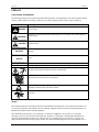
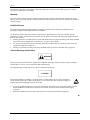
Siemens Industry, Inc.
INSTALLATION GUIDE
IG353-1
Rev 4
June 2010
PROCESS AUTOMATION CONTROLLER
Design Levels A and B
IG353-1
Contents
TABLE OF CONTENTS
SECTION AND TITLE
PAGE
PREFACE .................................................................................................................................................... ii
1.0 INTRODUCTION ............................................................................................................................................. 1-1
1.1 PRODUCT DESCRIPTION.......................................................................................................................... 1-1
1.2 CONFIGURATION ...................................................................................................................................... 1-3
1.3 PRODUCT LABELS..................................................................................................................................... 1-3
1.4 TYPICAL SHIPMENT CONTENTS............................................................................................................ 1-4
1.5 CUSTOMER/PRODUCT SUPPORT ........................................................................................................... 1-5
2.0 INSTALLATION .............................................................................................................................................. 2-1
2.1 INSTALLATION CONSIDERATIONS....................................................................................................... 2-1
2.2 ENVIRONMENTAL CONSIDERATIONS ................................................................................................. 2-2
2.3 MECHANICAL INSTALLATION............................................................................................................... 2-2
2.3.1 Installing Removable Connectors and Cover........................................................................................ 2-2
2.3.2 Panel and Rack Mounting Guidelines................................................................................................... 2-3
2.3.3 Station Mounting................................................................................................................................... 2-4
2.4 ELECTRICAL INSTALLATION ................................................................................................................. 2-4
2.4.1 Wiring Guidelines ................................................................................................................................. 2-5
LIST OF ILLUSTRATIONS
FIGURE AND TITLE
1-1
1-2
1-3
2-1
2-2
2-3
2-4
2-5
PAGE
Model 353, Design Level A ............................................................................................................................... 1-2
Model 353, Design Level B ............................................................................................................................... 1-2
Sample Product Labels....................................................................................................................................... 1-3
Cover Installation and Removal......................................................................................................................... 2-2
Panel Cutout Dimensions ................................................................................................................................... 2-3
Model 353 Dimensions ...................................................................................................................................... 2-3
Case Mounting Clip ........................................................................................................................................... 2-4
Rear Terminal Layout and Terminal Assignments............................................................................................. 2-7
LIST OF TABLES
TABLE AND TITLE
PAGE
1-1 Hardware/Features for Design Levels A and B ................................................................................................. 1-1
2-1 Rear Terminal Assignments ............................................................................................................................... 2-8
PAC 353 is a trademark of Siemens Industry, Inc. All product designations may be trademarks or product names of Siemens Industry,
Inc. or other supplier companies whose use by third parties for their own purposes could violate the rights of the owners.
Siemens Industry, Inc. assumes no liability for errors or omissions in this document or for the application and use of information included in this
document. The information herein is subject to change without notice.
Procedures in this document have been reviewed for compliance with applicable approval agency requirements and are
considered sound practice. Neither Siemens Industry, Inc. nor these agencies are responsible for product uses not included in the
approval certification(s) or for repairs or modifications made by the user.
June 2010
i
Contents
IG353-1
PREFACE
Conventions and Symbols
The following symbols may be used in this manual and may appear on the equipment. The reader should be familiar
with the symbols and their meanings. Symbols are provided to quickly alert the reader to safety related text.
Symbol
DANGER
Meaning
Indicates an immediate hazardous situation which, if not avoided, will result in death or
serious injury.
WARNING
Indicates a potentially hazardous situation which, if not avoided, could result in death or
serious injury.
CAUTION
Indicates a potentially hazardous situation which, if not avoided, may result in minor or
moderate injury.
CAUTION
NOTICE
IMPORTANT
Note
Indicates a potentially hazardous situation which, if not avoided, may result in property
damage.
Indicates a potential situation which, if not avoided, may result in an undesirable result or
state.
Identifies an action that should be taken to avoid an undesirable result or state.
Identifies supplemental information that should be read before proceeding.
Electrical shock hazard – Either symbol indicates the presence of an electrical shock
hazard. The associated text states the nature of the hazard.
Explosion hazard – Symbol indicates that the danger of an explosion hazard exists. The
associated text states the nature of the hazard.
Electrostatic discharge – The presence of this symbol indicates that electrostatic
discharge can damage the electronic assembly.
Pinch hazard – Symbol indicates that a pinch hazard exists if correct procedures are not
followed.
Scope
This manual provides basic mechanical and electrical installation information for use by experienced installers. It is
to be used in conjunction with a Model 353 User’s Manual, supplied on the Siemens Process Instrumentation User
Manual CD included with the controller shipment.
This manual does not purport to cover all details or variations in equipment or to provide for every possible
contingency to be met in connection with installation, operation, or maintenance. Should further information be
desired or should particular problems arise which are not covered sufficiently for the purchaser’s purposes, the
matter should be referred to a support group listed in the Customer/Product Support section of this manual or to a
ii
June 2010
IG353-1
Contents
local Siemens sales office. The contents of this manual shall not become part of or modify any prior or existing
agreement, commitment or relationship.
Warranty
The sales contract contains the entire obligation of Siemens. The warranty contained in the contract between the
parties is the sole warranty of Siemens. Any statements continued herein do not create new warranties or modify the
existing warranty.
Qualified Persons
The described equipment should be installed, configured, operated, and serviced only by qualified persons
thoroughly familiar with this guide and the User’s Manual.
For the purpose of these documents and the product labels, a qualified person is one who is familiar with the
installation, assembly, commissioning, and operation of the product, and who has the appropriate qualifications for
their activities such as:
• Training, instruction, or authorization to operate and maintain devices/systems according to the safety standards
for electrical circuits, high pressures, and corrosive, as well as, critical media.
• For devices with explosion protection: training, instruction or authorization to work on electrical circuits for
systems that could cause explosions.
• Training or instruction according to the safety standards in the care and use of suitable safety equipment.
General Warnings and Cautions
WARNING
The perfect and safe operation of the equipment is conditional upon proper transport, proper storage, installation
and assembly, as well as, on careful operation and commissioning.
The equipment may be used only for the purposes specified in this manual.
CAUTION
Electrostatic discharge can damage or cause the failure of semiconductor devices such as integrated
circuits and transistors. The symbol at right appears on a circuit board or other electronic assembly to
indicate that special handling precautions are needed.
•
•
A properly grounded conductive wrist or heel strap must be worn whenever an electronics module or circuit
board is handled or touched. Static control kits are available from most electrical and electronic supply
companies.
Electronic assemblies must be stored in static protective bags when not installed in equipment.
!
June 2010
iii
Contents
IG353-1
Changes for Revision 4, June 2010
Section
Cover
Section 1, Introduction
Section 2, Installation
iv
Change
Banner updated
Revision number and date changed
Figure 1-3 and Customer/Product Support updated
Updated Section 2.4.1 Wiring Guidelines and the notes in Figure 2-5 and Table 2-1
June 2010
IG353-1
Contents
1.0 INTRODUCTION
This Installation Guide contains mechanical and electrical installation procedures for Siemens 353 Process
Automation Controllers, Design Level A and Design Level B. It is intended for use by experienced installers. The
Design Levels support various hardware (circuit board) assemblies and performance features as shown in Table 1-1.
Detailed product specifications and procedures to bench test, install, configure, calibrate, and service the 353 are
included in the appropriate 353 User’s Manual.
Table 1-1 Hardware/Features for Design Levels A and B
Controller Design
Level
Hardware/Features Supported
•
•
A
•
B
•
•
•
•
User’s Manual ID
MPU Controller Board and optional I/O Expander Board
Option Boards for LIL or Ethernet communications,
LonWorks remote I/O, Real Time Clock and Configuration
Backup
MODBUS communications is standard - See Figure 1-1
UM353-1
MPU Controller Board and optional I/O Expander Board
MultiMediaCard for configuration backup
Real Time Clock is standard
Ethernet and MODBUS communications are standard - See
Figure 1-2
UM353-1B
User’s Manuals are located on the supplied Siemens Process Instrumentation User Manual CD. Perform the brief
procedure below to access the manuals. The manuals are in Portable Document Format (PDF). A link for
downloading the free Adobe® Reader® is provided.
1. Insert the CD into your computer’s CD drive.
2. Select the desired manual from the menu:
• If autorun is enabled a menu of available manuals will appear. Click on the link to the desired manual.
• If autorun is not enabled, go to Start > Run and navigate to the CD. Double click on Autorun.exe
and then click Run to display the menu of available manuals.
1.1 PRODUCT DESCRIPTION
The Model 353 offers the control system designer the ultimate in flexibility and capability for the implementation of
continuous solutions and batch solutions. At the time this manual was printed, the controller was available in two
versions: hardware design level A and hardware design level B. An exploded view of a design level A controller
appears in Figure 1-1. Figure 1-2 shows a design level B controller.
Design level A controllers have an MPU Controller board and revision 3 firmware. An I/O Expander board for
additional I/O is an option. These controllers can also have several other option boards mounted on the MPU
Controller board. These option boards provide Local Instrument Link or Ethernet network communications,
LonWorks communications, and Real Time Clock/Configuration Backup capability. Refer to the labels on the
controller case (see Section 1.3 Product Labels) for the model designation which specifies the installed hardware.
For an explanation of each character in the model designation, refer to the UM353-1, Section 14 Model Designation
and Specifications.
Design level B controllers have an MPU Controller board and revision 4 firmware. An I/O Expander board for
additional I/O is an option. These controllers provide enhanced performance with an advanced microprocessor and
additional memory, standard Ethernet communications, and configuration backup to a MultiMediaCard. Refer to the
labels on the controller case for the model designation which specifies the installed hardware. For an explanation of
each character in the model designation, refer to UM353-1B, Section 13 Model Designation and Specifications.
June 2010
1-1
Introduction
IG353-1
Connector Cover*
Ground Screw*
Voltage Input, Approvals, and
Warning Label*
Mounting Clip,
Top and Bottom*
Warning and I/O
Capacity Label*
Nameplate*
LIL or Ethernet
Network Board
I/O Expander
Board
RTC/CB or
RCB Board
Removable
Portions of
Connectors*
Accessory or
Option Boards
Connector Socket
Assembly*
Future
Use
Mounting Kit, Accessory Boards
LonWorks
Board
MPU Controller Board
Ethernet
Cable
MG00392b
RJ-45 Ethernet Connector*
Case with Flange*
O-Ring, Display Assembly
Display Assembly with Operator Faceplate
Communication Port on Underside
* = Case Assembly
Flip-Down Door with Loop ID Card
Warning Label
FIGURE 1-1 Model 353, Design Level A
Connector Cover*
Ground Screw*
Voltage Input, Approvals, and
Warning Label*
Mounting Clip,
Top and Bottom*
O-Ring, Display
Assembly
Warning and I/O
Capacity Label*
Nameplate*
I/O Expander
Board
Removable
Portions of
Connectors*
Connector Socket
Assembly*
RJ-45 Ethernet Connector*
Case with Flange*
Ethernet Connector
MPU Controller Board
Warning Label
Display Assembly Cable
MG00500a
Display Assembly with
Operator Faceplate
Communications
Port on Underside
MultiMediaCard Socket
Flip-Down Door with Loop ID Card
* = Case Assembly
FIGURE 1-2 Model 353, Design Level B
1-2
June 2010
IG353-1
Introduction
1.2 CONFIGURATION
The controller must be configured before it can be used to control a process. It can be configured either locally or
remotely. The local faceplate includes buttons located behind a flip-down door for complete configuration
including the addition/deletion of loops and function blocks and the editing of function block parameters. Refer to
the User’s Manual for detailed configuration procedures.
1.3 PRODUCT LABELS
This section provides sample labels to assist in identifying the controller model at hand.
IMPORTANT
Before installing or servicing a controller, refer to the controller labels and the applicable
specifications and hazardous area classifications in the User’s Manual to ensure that the
correct model with the needed certifications is at hand.
Each controller is identified by several labels located on the case and inside the drop-down door on the Display
Assembly, as shown in Figure 1-1. Sample labels are shown below.
Input
Requirements
120/240 VAC
25 W
47-63 Hz
40 VA
Max Amb. 50°C
WARNING:
Substitution of
components may impair
the suitability for Class
1, Div. 2
LR38024
WARNING: Do not connect or
disconnect configuration port cable while
in a hazardous location.
Do not remove the rear terminal housing.
Siemens Industry, Inc.
Model No.
353A4F1NNLNNNA4
Sales No.
nnnnnnnnnn-nnnnnn
Serial No.
nnnnnnnn
Design Level
is next to last
character in
Model No.
Typical Input and Output Capacity:
CLI, Div. 2, GPS A,
B, C, & D
Temp Code T4A
See UM353-1
Xmtr. Pwr. Sply. Out. - 25V @ 120 mA
Anlg. inp. V. - 0 to 5 Vdc @ 30uA
Anlg. out. cur. - 4 to 20 mA @ 800 Ohms
Dgtl. inp. V. - 0 to 30 Vdc @ 5 mAdc
Dgtl. out. cur. - 100 mA @ 30 Vdc
Rly. out. - 5A @ 120V, 2.5A @ 240 Vac
Max. Ambient Temp 50°C
FIGURE 1-3 Sample Product Labels
June 2010
1-3
Introduction
IG353-1
1.4 TYPICAL SHIPMENT CONTENTS
The items listed below are those typically included in a shipment and are subject to change.
1.
Model 353 Process Automation Controller, model number per order, qty. 1; includes mounting case, connector
socket assembly and rear terminal cover
2.
Power Input and Range Resistor Kit, PN 16354-30, qty. 1
DESCRIPTION
Resistor, 250Ω, 0.1%, 3W, WW
Sleeving
Crimp-On Connector
Kit Installation Instruction
Shunt (Not used in Design Level B
controller)
3.
QUANTITY
3
3
6
1
1
Mounting Clip Kit, no part number, qty. 1
Contents: 2 Mounting Clips and 2, 8-32 x 1 Screws (see the Parts List at back of the User’s Manual for part
numbers)
4.
I/O Expander Board Kits
PN16353-52 I/O Expander Board Kit - The I/O Expander Board is factory installed when a Model 353 with
Expansion Board option 1 is ordered.
•
When adding an I/O Expander board to a Standard Case with Ethernet connector (case Option 4), no
additional connectors need be ordered.
•
For field installation of this kit, see the supplied Kit Installation Instruction (15900-390).
DESCRIPTION
I/O Expander Board - Do not remove Board from static shielding
bag until it is to be installed.
Range Resistor and Reference Junction Kit, see below
QUANTITY
1
1
PN16353-49 Range Resistor and Reference Junction Kit - This kit is supplied with the above I/O Expander
Board Kit and with a factory shipped Model 353 with Expansion Board option 1.
DESCRIPTION
4-20 mA to 1-5V Range Resistor, 250Ω, 0.1%, 3W, WW
4-20 mA to 15-75 mV Range Resistor, 3.75Ω, 0.1%, 3W, WW
Sleeving
Crimp-On Connector
TC Reference Junction, 100Ω
Kit Installation Instruction
QUANTITY
1
2
5
6
2
1
5.
Siemens Process Instrumentation User Manuals CD; qty 1. The CD contains UM353-1, Model 353 (Design
Level A) User’s Manual and UM353-1B, Model 353 (Design Level B) User’s Manual.
6.
Printed copy of Model 353 Installation Guide IG353-1 (this guide), qty. 1.
7.
Two warning labels that are to be placed in a highly visible location near the case rear terminals.
8.
Additional items as required by your order. Refer to the packing list accompanying a shipment.
1-4
June 2010
IG353-1
Introduction
1.5 CUSTOMER/PRODUCT SUPPORT
This section provides Siemens’ Internet site addresses, e-mail address, telephone number, and related information
for contacting customer/product support.
IMPORTANT
An instrument must be thoroughly cleaned (decontaminated) to remove any process materials,
hazardous materials, or blood born pathogens prior to return for repair. Read and complete the
Siemens RMA form(s).
For support and the location of your local Siemens representative, refer to the table below for the URL of the
Process Instrumentation (PI) portion of the Siemens public Internet site. Once at the site, click Support in the right
column and then Product Support. Next select the type of support desired: sales, technical (see the table below),
documentation, or software.
Online Support Request
http://www.siemens.com/automation/support-request
Technical Support
1-800-333-7421; 8 a.m. to 4:45 p.m. eastern time, Monday through Friday (except
holidays)
Customer Service & Returns
1-800-365-8766 (warranty and non-warranty)
Public Internet Site
http://www.usa.siemens.com/pi
Technical Publications
in PDF
Click the above link to go to the PI home page. Click Support and then Manuals
and then, under “Additional Manuals,” select the product line (e.g. Control
Solutions)
!
June 2010
1-5
Introduction
1-6
IG353-1
June 2010
IG353-1
Installation
2.0 INSTALLATION
This section outlines installation of a Siemens Model 353 Process Automation Controller. Refer to the proper Model
353 User’s Manual for detailed procedures, critical safety warnings and cautions, product specifications, and agency
approvals.
IMPORTANT
The installation must conform to the National Electrical Code and all other
applicable construction and electrical codes.
Section 1.4 in this guide has a list of the items in a typical controller shipment. If
the Display Assembly or one or more circuit boards must be installed in the case,
go to the Assembly Replacement section of a 353 User’s Manual for installation
information, including the setting of any involved jumpers.
For agency approvals and installations in a hazardous area, refer to the Agency
Approvals section of a 353 User’s Manual. CSA Hazardous Location Precautions
and Special Conditions for Safe Use are included in the manual. Use of the
equipment in a manner not specified by the manufacturer may impair the
protection provided by the equipment.
Two warning labels, shown here, are included with the controller. Install them in a
highly visible location near the controller’s rear terminals to insure that personnel
with access to controller terminals are aware of a potential electrical shock hazard
and, if installation is in a hazardous area, possible explosion hazard.
2.1 INSTALLATION CONSIDERATIONS
A Model 353 is intended for flush panel mounting in a vibration free instrument panel or rack in an indoor or
sheltered location. Mount a single controller in a single-station panel cutout or mount several controllers in a row in
a multiple-station panel cutout. For a watertight panel, mount each controller in a single-station cutout.
The controller can be mounted in a user-supplied enclosure located out-of-doors or in a location whose
environmental parameters exceed controller operating specifications. A thin bead of silicon sealant is often applied
between the controller’s Display Assembly and the mounting panel to prevent air or liquid leakage at this joint.
Do not mount the controller where direct sunlight can strike the faceplate or case. Direct sunlight can make the
displays difficult to read and will interfere with heat dissipation.
Mount the controller either horizontally or with a backward tilt (i.e. the front of the case higher than the rear). If the
controller is to be mounted with electronic recorders or with pneumatic recorders or stations, tilt back restrictions
for these units can have a bearing on panel design and layout.
Route electrical power to the controller through a clearly labeled circuit breaker, fuse, or on-off switch that is
located near the controller and is accessible by the operator. The breaker or switch should be located in a nonexplosive atmosphere unless suitable for use in an explosive atmosphere.
Thermocouple inputs are accommodated with an I/O Expander board and a Reference Junction temperature sensor.
At the factory, two Reference Junctions are included in a Range Resistor and Reference Installation Kit.
June 2010
2-1
Installation
IG353-1
2.2 ENVIRONMENTAL CONSIDERATIONS
Operate a controller within its environmental specifications to help ensure reliable, trouble-free operation with
minimum down time. Refer to the Model Designation and Specifications section of a 353 User’s Manual for
controller operating temperatures limits, operating humidity, and maximum moisture content.
CAUTION
Exceeding the specified operating temperature limits can adversely affect
performance and may cause damage to the controller.
2.3 MECHANICAL INSTALLATION
The following subsections provide guidelines and procedures for mounting controllers in a panel or rack. The
installation should be structurally rigid and the controllers should be squared in the panel or rack.
2.3.1 Installing Removable Connectors and Cover
Typically, the cover and connectors are supplied in a bag for installation by the user. Each connector has a
removable portion that can be wired and then mated to the fixed portion mounted on the back of the controller case.
1.
Refer to the Electrical Installation section of this manual and connect the wiring and components (e.g. range
resistors, thermocouple cold junction) to the removable portions of the supplied connectors.
2.
Align the removable portion of a connector with the fixed portion on the back of the case. Press the removable
portion of onto the fixed portion. Fully seat the connector.
3.
Tighten the two captive screws. Do not over tighten. Check that wires and components remain connected
securely.
4.
Repeat the above steps for each connector.
5.
Dress wires, cables, and components for cover installation. Remove the protective paper from the cover. Install
the cover as shown in Figure 2-1.
To Install Terminal Cover:
To install or
remove cover:
squeeze
both sides
~1/16"
to clear
alignment
tabs.
1. Orient the cover as shown. Note the four hooked
tabs and Ethernet cable clearance cutout.
2. Squeeze the cover slightly at the two small cutouts
in the cover edges and fully insert the four hooked
cover tabs in the rear panel slots.
3. Allow cover sides to relax. Pull the cover straight
down until it snaps into place. The cutouts in the
cover edges will engage two alignment tabs on
the rear panel.
Where needed, the Ethernet cable should exit
through the large cutout in the cover.
To Remove Cover:
AG00327a
1. Squeeze the cover slightly at the two cutouts
in the cover edges (about 2" down from the
top of the cover) and push cover upward.
2. Pull cover out from rear panel.
Ethernet cable cutout.
FIGURE 2-1 Cover Installation and Removal
2-2
June 2010
IG353-1
Installation
2.3.2 Panel and Rack Mounting Guidelines
The panel face should provide a flat and rigid mounting surface. Reinforce the back of the panel if there is a
possibility that the panel face will bow. Raceways, conduit, and wiring should not interfere with accessibility of
instruments, control devices, alarms, and related equipment. See Figures 2-2, 2-3, and 2-4.
5.44 +0.06/-0
[138.2 +1.5/-0]
Dimensions: Inches [Millimeters]
W
X03100S1
Panel Cutout Dimensions: Tolerances +0.06/-0 [+1.5/-0]
Height = 5.44 [138.2]
Width = (2.84 X A) - 0.16 inches
[(72.0 X A) - 4.1] mm
Where: A= Number of 353 Stations and 353R or i|pac Faceplates
FIGURE 2-2 Panel Cutout Dimensions
11.25
(285.8)
2.84
(72)
2.67
(67.8)
1.18
(30)
Case
Flange
MG00391a
TOP VIEW
Mounting Clip
Dimensions in inches (millimeters)
SIDE VIEW
5.67
(144)
5.42
(137.7)
6.3
(160)
0.32
Max.
(0.8)
FIGURE 2-3 Model 353 Dimensions
June 2010
2-3
Installation
IG353-1
2.3.3 Station Mounting
A straight slot screwdriver with at least a 10" (254 mm) shank is needed to tighten the two mounting clip screws.
1.
Locate the supplied Mounting Clip Kit. It contains two mounting clips and two 8-32 x 1" fillister head screws.
Thread the mounting screws into the mounting clips. See Figure 2-4.
2.
At the front of the panel, insert the controller case into the panel cutout until the case flange contacts the front
of the panel.
3.
From behind the panel, slightly rotate the top mounting clip to fit into the case cutout. Then straighten the clip
and partially tighten the mounting screw. Insert, straighten and partially tighten the bottom clip.
4.
Square the case with the panel.
5.
Alternately tighten top and bottom mounting clip screws until the case is secured to the panel. Do not over
tighten and distort the case.
Side View
Insert clip as shown
and straighten
Bottom View
X03103S0
FIGURE 2-4 Case Mounting Clip
2.4 ELECTRICAL INSTALLATION
This section contains electrical connection guidelines for wiring a Model 353. Each case rear connector and
terminal is identified.
WARNING
Electrical shock hazard
Explosion hazard
Can cause death or injury
•
•
•
2-4
Remove power from all wires and terminals before working on equipment.
In a potentially hazardous atmosphere, remove power from equipment before
connecting or disconnecting power, signal, or other circuit.
Observe all pertinent regulations regarding installation in hazardous area.
June 2010
IG353-1
Installation
2.4.1 Wiring Guidelines
Electrical Connections - Power, I/O, and network connections to a basic controller are completed through
removable connectors using terminals H, N, and 3-26. When the controller includes an I/O Expander board,
connectors with terminals 27-52 are also used. The case has an Ethernet connector for use when an Ethernet
capability is included and the MPU Controller board firmware is V2.4 or later. Connector locations are shown in
Figure 2-5. Individual terminals functions are also identified in Table 2-1.
Connectors - Power terminals are identified by a letter: Hot and Neutral. The ground connection is made to a green
case/safety ground screw located above the connectors. Signal I/O terminals are identified by a number: 3 through
52. A connector terminal will accept the following wire(s).
• one 14-22 AWG (2.1-0.38 mm2)
• two 16 AWG (1.3 mm2)
• three 18 AWG (0.96 mm2)
Wire Size Recommendations:
• signal wiring - 18 AWG (0.96 mm2)
• power wiring - 18 AWG (0.96 mm2)
Wire Stripping Recommendations:
• connector terminal wiring - 1/4" (6 mm) to 5/16" (8 mm)
• green ground screw wiring - 1/8" (10 mm) to 1/2" (13 mm)
Be careful not to nick the conductor or cut away strands.
Wire Selection - Stranded wire is recommended for most connections, however, solid wire is typically used for
thermocouple extension wire. Carefully select wire size, conductor material, and insulation. Some selection
considerations are:
• current and voltage to be carried
• total length of each wire run
• whether wire will be bundled or run singly
• indoor or outdoor installation
• temperature extremes (Use supply wires suitable for 5°C (10°F) above ambient temperature.)
• exposure to sunlight
• vibration
• types of contaminates
Station Common (COM), Terminal 6:
• Connect station common to the user’s instrument bus common at only one point.
• Station common is electrically isolated from case/safety ground, the green ground screw.
• Terminals 6, 9, 18, 21, 24, 34, 40 and 42 are electrically connected. Use the terminals that allow the best wire routing and
the least stress on components, such as range resistors.
Digital Input Commons (DIN#-), Terminals 12, 14, and 16 - Digital input commons are isolated from each other,
from station common and from case/safety ground.
Connector Terminal and Ground Screw Torque Specifications:
• connector terminals - 5 in. lbs (0.56 N m)
• green case/safety ground screw - 20 in. lbs (2.26 N m)
June 2010
2-5
Installation
IG353-1
Range Resistors - Supplied range resistors are either 250Ω or 3.75Ω. These are
0.1%, 3W, wire wound precision resistors. Get a range resistor from the
installation kit and insulate the bent resistor lead with a piece of sleeving. At the
lead end, approximately 1/4" (6 mm) to 5/16" (8 mm) of bare resistor lead should
be exposed.
0.8"
(20.3mm)
Place sleeving
on this lead.
0.5"
(12.7mm)
MG000631
Crimp-On (solderless) Connectors - A pin-style crimp-on connector can be used when two or more wires or a
combination of wires and component leads are to be inserted into a connector terminal at the rear of the case. Wires
and leads are crimped in the connector and the connector pin inserted in the
Crimp-On
selected connector terminal. The connector can provide a more secure
Connector
Signal Input Wire
connection when multiple leads are involved. An example of its use is shown at
right. Several crimp-on connectors are provided in various Model 353
installation kits and they are available from most electrical supply sources.
Range Resistor
Wire Routing and Conduit - DC wiring should be separated from AC wiring and away from AC powered
pushbuttons, alarms, annunciators, motors, solenoids, and similar devices. Conduit and raceways are commonly
used for routing panel wiring. Wiring not installed in conduit or raceway should be clamped or supported
approximately every 12 inches (300 mm).
Thermocouple Reference Junction - Slip a length of insulating sleeving over the portion of each reference junction
lead that will remain exposed after installation. Carefully form the leads and install the cold junction as shown
below.
0.06
(1.5)
0.63
(15.9)
43
44
45
0.5
(12.7)
Notes:
1. Insulate leads with sleeving.
2. Dimensions are in inches (millimeters)
and are approximate.
MG00390a
0.1
(0.25)
46
Note:
Place Reference Junctions
against the connector
and as close to the
Connector Socket
Assembly as possible.
48
Analog Input Universal 1 d
49
Analog Input Universal 2 a
Connector Socket
Assembly
2-6
Analog Input Universal 1 a
Reference Junction for AINU1
Reference Junction for AINU2
47
50
51
52
Analog Input Universal 2 d
AG00325a
0.3
(7.9)
June 2010
IG353-1
Installation
Terminal Function, ID, and Number
Network Communications A, NCA, 3
Case/Safety Ground
H
Network Communications B, NCB, 4
Transmitter Power 26 Vdc+, XMTR+, 5
3
Transmitter/Station Common, COM, 6
21
N
35
Transmitter Power, 26 Vdc+, XMTR+, 7
Digital Output 1+, DOUT1+, 8
Digital Outputs 1/2 Common, DOUTC, 9
Digital Output 2+, DOUT2+, 10
Digital Input 1+, DIN1+, 11
Power Input
AC Hot or DC+, H
AC Neutral or DC-, N
Digital Input 1-, DIN-, 12
Digital Input 2+, DIN2+, 13
Digital Input 2-, DIN2-, 14
Digital Input 3+, DIN3+, 15
34
Digital Input 3-, DIN3-, 16
Analog Output 1+, AOUT1+, 17
Analog Output 1/2 Common, AOUTC, 18
Analog Output 2+, AOUT2+, 19
Analog Input 1+, AIN1+, 20
Terminal Function, ID, and Number
Analog Input 1/2 Common, AINC, 21
Analog Input 2+, AIN2+, 22
Analog Input 3+, AIN3+, 23
Analog Input 3 Common, AINC, 24
I/O Bus A, IOA (design level A only), 25
I/O Bus B, IOB (design level A only), 26
Relay Output 1 Normally Closed, ROUT1nc, 27
Relay Output 1 Common, ROUT1c, 28
Relay Output 1 Normally Open, ROUT1no, 29
Relay Output 2 Normally Closed, ROUT2nc, 30
Relay Output 2 Common, ROUT2c, 31
Relay Output 2 Normally Open, ROUT2no, 32
Analog Output 3+, AOUT3+, 33
AG00326d
Analog Output 3 Common, AOUTC, 34
Ethernet
Connector
20
52
Terminal Number, Function, and ID
35, Digital Input Universal 1+, DINU1+
36, Digital Input Universal 1-, DINU137, Digital Input Universal 2+, DINU2+
38, Digital Input Universal 2-, DINU239, Transmitter Power 26 Vdc+, XMTR+
40, Transmitter/Station Common, COM
41, Analog Input 4+, AIN4+
42, Analog Input Common, AINC
43, Digital Input 4+, DIN4+
44, Digital Input 4-, DIN445, Analog Input Universal 1 a, AINU1a
46, Analog Input Universal 1 b, AINU1b
47, Analog Input Universal 1 c, AINU1c
48, Analog Input Universal 1 d, AINU1d
49, Analog Input Universal 2 a, AINU2a
50, Analog Input Universal 2 b, AINU2b
51, Analog Input Universal 2 c, AINU2c
52, Analog Input Universal 2 d, AINU2d
Notes:
1. Terminal numbers are shown on each connector. The plug-in portions of the connectors are packed with a case.
The connectors are keyed.
2. Case/Safety Ground - Connect to green screw at top center of rear terminal area.
3. NCA and NCB
Design Level A - Connect LIL Twinaxial Cable or twisted pair wiring. Refer to UM353-1, Section 8.4.9 for
additional details.
Design Level B - Connect Modebus cable or twisted pair wiring. Refer to UM353-1B, Section 7.4.9 for
additional details.
4. IOA and IOB
Design Level A - LonWorks bus connections. Twisted pair wiring is typical.
Design Level B - No connection
5. Ground Bus - An external, user-supplied ground bus can ease connection of multiple grounds, particularly when
twinaxial cable shields are to be grounded.
6. Terminals 6, 9, 18, 21, 24, 34, 40, and 42 are electrically connected. Use the terminals that allow the best wire
routing and the least stress on components, such a range resistors.
FIGURE 2-5 Rear Terminal Layout and Terminal Assignments
June 2010
2-7
Installation
IG353-1
TABLE 2-1 Rear Terminal Assignments
CONTROLLER BOARD
Description
Power – AC Hot/ DC +
Power – AC Neutral/DC Network Communication A
Network Communication B
Transmitter Power 26Vdc +
Transmitter/Station Common
Transmitter Power 26Vdc +
Digital Output 1 +
Digital Outputs 1/2 Common
Digital Output 2 +
Digital Input 1 +
Digital Input 1 Digital Input 2 +
Digital Input 2 Digital Input 3 +
Digital Input 3 Analog Output 1 +
Analog Output 1/2 Common
Analog Output 2 +
Analog Input 1 +
Analog Input 1/2 Common
Analog Input 2 +
Analog Input 3 +
Analog Input 3 Common
I/O Bus A (design level A only)
I/O Bus B (design level A only)
Ethernet
ID
I/O EXPANDER BOARD
#
#
ACH/DC+
H
27
ACN/DCN
28
NCA
3
29
NCB
4
30
XMTR+
5
31
COM
6
32
XMTR+
7
33
DOUT1+
8
34
DOUTC
9
35
DOUT2+
10
36
DIN1+
11
37
DIN112
38
DIN2+
13
39
DIN214
40
DIN3+
15
41
DIN316
42
AOUT1+
17
43
AOUTC
18
44
AOUT2+
19
45
AIN1+
20
46
AINC
21
47
AIN2+
22
48
AIN3+
23
49
AINC
24
50
IOA
25
51
IOB
26
52
Separate RJ-45 Connector
ID
Description
ROUT1nc
ROUT1c
ROUT1no
ROUT2nc
ROUT2c
ROUT2no
AOUT3+
AOUTC
DINU1+
DINU1DINU2+
DINU2XMTR+
COM
AIN4+
AINC
DIN4+
DIN4AINU1a
AINU1b
AINU1c
AINU1d
AINU2a
AINU2b
AINU2c
AINU2d
Relay Output 1 Normally Closed
Relay Output 1 Common
Relay Output 1 Normally Open
Relay Output 2 Normally Closed
Relay Output 2 Common
Relay Output 2 Normally Open
Analog Output 3 +
Analog Output 3 Common
Digital Input Universal 1 +
Digital Input Universal 1 Digital Input Universal 2 +
Digital Input Universal 2 Transmitter Power 26Vdc +
Transmitter/Station Common
Analog Input 4 +
Analog Input Common
Digital Input 4 +
Digital Input 4 Analog Input Universal 1 a
Analog Input Universal 1 b
Analog Input Universal 1 c
Analog Input Universal 1 d
Analog Input Universal 2 a
Analog Input Universal 2 b
Analog Input Universal 2 c
Analog Input Universal 2 d
Notes:
1. # - Terminal letters and numbers are printed on individual connectors. Model 353_1_N… has 2 connectors; Model
353_2_1… has 4 connectors and an I/O Expander board. (Underscore is a placeholder/wildcard; ellipsis indicates that
subsequent characters do not affect selection.)
2. Safety/Case Ground - Wire to green screw at top center of rear terminal area.
3. NCA and NCB
Design Level A – Connect LIL Twinaxial Cable or twisted pair wiring. Refer to UM353-1, Section 8.4.9 for additional
information.
Design Level B – Connect Modbus cable or twisted pair wiring. Refer to UM353-1B, Section 7.4.9 for additional
information.
4. IOA and IOB
Design Level A – LonWorks bus connections. Twisted pair wiring is typical.
Design Level B – No connection
5. Ground Bus - An external, user-supplied ground bus can ease connection of multiple grounds, particularly when twinaxial
cable shields are to be grounded.
6. Terminals 6, 9, 18, 21, 24, 34, 40 and 42 are electrically connected. Use the terminals that allow the best wire routing and
the least stress on components, such as range resistors.
!
2-8
June 2010