1
FUJITSU SEMICONDUCTOR
CM42-00410-2E
CONTROLLER MANUAL
2
F MC-16L/16/16H/16F
16-BIT MICROCONTROLLER
MB2140 Series EMULATOR
SETUP MANUAL
Windows Version
2
F MC-16L/16/16H/16F
16-BIT MICROCONTROLLER
MB2140 Series EMULATOR
SETUP MANUAL
Windows Version
FUJITSU LIMITED
PREFACE
■ Safe usage
This manual contains important information on the safe use of this product. Always read this
manual before using the product and always use in accordance with the instructions. In
particular, take special note of the section entitled “Safety Precautions” and perform appropriate
safety checks when using the product.
Also, please keep this manual available for reference when using the product.
■ Objectives and intended readership
This manual explains essential information about the emulator for the F2MC-16L/16LX/16F
microcontroller (MB2141A main unit and MB2145-507 emulation pod).
The manual is intended for engineers using the emulator to test and debug programs. The
manual describes how to set up the emulator.
The manual is for the Windows version of the emulator-debugger.
■ Operating environment for this product
The operating environment for the product is temperature between 5 and 40°C and humidity
between 30 and 80%. Avoid hot and humid conditions and do not allow condensation.
Do not block the ventilation holes or operate the product with the cover removed.
Place the product in as horizontal a position as possible. Do not use in conditions of severe
vibration or in an environment that is dusty or contains explosive gas.
If transporting the product, such as when returning for repair, it is recommended that the
packaging material supplied with the product be reused for protection.
Using the product in an environment that does not comply with the conditions described above
may result in unexpected injury to the user or to people and property in the vicinity.
■ Trademarks
Microsoft, MS-DOS, and Windows are trademarks of Microsoft Corporation registered in the
United States. and other countries.
IBM is a registered trademark of International Business Machines Corporation of the United
States.
IBM PC/AT is a trademark of International Business Machines Corporation of the United
States.The PC-9800 series are products of NEC Corp.
System names and product names that appear in this manual are the trademarks of their
respective firms or organizations. They are not always indicated with™ and ®.
■ Safety Warnings
Important warnings items are given on the following pages.
Before using the emulation pod, read each warning and make a safety check.
i
Indicates that improper use may cause minor or moderate
injury, or may damage the emulation pod, connected
equipment, data or other software resources, or other
property.
CAUTION
Symbol
Electric shock
Description
There is a danger of electric shock.
Always disconnect the power before connecting or
disconnecting connectors, cables, the MCU, or
other components.
Page
19
*:Take care with the following when setting up the hardware.
• To prevent damage to the equipment, always disconnect the power before connecting or
disconnecting connectors, cables, the MCU, or other components.
• To prevent broken wires, always grip the connector when disconnecting cables.
• The probe cable has a very fine tip. To prevent damage, take care not to use excessive
force when attaching or removing the probe.
■ Configuration of this manual
This manual consists of the following four chapters and an appendix.
Chapter1 Product Checks
This chapter describes each of the products required to use the emulator.
Chapter2 Hardware Setup
This chapter describes how to connect the MB2140 to the host computer and user system.
Chapter3 Software Setput
This chapter describes how to setup the software environment on the host computer and
emulator so as to use the emulator.
Chapter 4 Operation Procedures
This chapter describes the operation, setup, and other procedures required to use the
emulator in practice.
Appendices
The appendices describe the treatment of user system pins required to operate the MCU,
the setup procedure for the MB2140 series emulator (for the F2MC-16L/16/16H/16F series),
and the setup checklist.
■ Related manuals
Please refer also to the following manuals.
The manuals listed below are provided with their associated development tools.
ii
MB2140 series manuals:
Name
Code
MB90600/700/700H/200 Series
Emulator-Debugger Manual
(Windows Version)
CM43-00301-X
MB90600/700/700H/200 Series
Emulator-Debugger Installation Manual
(Windows Version)
SI3407-X
2140 Main Unit
User Manual
CM41-00410-X
MB2145-507
Hardware Manual
CM41-00411-X
10BASE-2 LAN Adaptor [MB2142-01]
User Manual
CM41-00411-X
10BASE-T LAN Adaptor [MB2142-02]
User Manual
CM41-00412-X
Parallel Communication Adaptor [MB214203]
User Manual
CM41-00413-X
MCU Hardware Manuals
CMXX-XXXXX-X
Comment
Describes
command
operation and
similar for the
MB2140 series.
Describes
information
about the
associated
product such as
its structure and
connections.
iii
1. The contents of this document are subject to change without notice. Customers are advised to consult
with FUJITSU sales representatives before ordering.
2. The information and circuit diagrams in this document are presented as examples of semiconductor
device applications, and are not intended to be incorporated in devices for actual use. Also, FUJITSU is
unable to assume responsibility for infringement of any patent rights or other rights of third parties
arising from the use of this information or circuit diagrams.
3. The contents of this document may not be reproduced or copied without the permission of FUJITSU
LIMITED.
4. FUJITSU semiconductor devices are intended for use in standard applications (computers, office
automation and other office equipments, industrial, communications, and measurement equipments,
personal or household devices, etc.).
CAUTION:
Customers considering the use of our products in special applications where failure or abnormal
operation may directly affect human lives or cause physical injury or property damage, or where
extremely high levels of reliability are demanded (such as aerospace systems, atomic energy controls,
sea floor repeaters, vehicle operating controls, medical devices for life support, etc.) are requested to
consult with FUJITSU sales representatives before such use. The company will not be responsible for
damages arising from such use without prior approval.
5. Any semiconductor devices have inherently a certain rate of failure. You must protect against injury,
damage or loss from such failures by incorporating safety design measures into your facility and
equipment such as redundancy, fire protection, and prevention of over-current levels and other
abnormal operating conditions.
6. If any products described in this document represent goods or technologies subject to certain
restrictions on export under the Foreign Exchange and Foreign Trade Control Law of Japan, the prior
authorization by Japanese government should be required for export of those products from Japan.
©2000 FUJITSU LIMITED Printed in Japan
iv
Reading This Manual
■ Page layout
As each section of this manual covers either one page or one spread, the contents of each
section can be read without needing to turn pages.
A summary of each section appears below the section title. You can obtain a rough overview of
the product by reading through these summaries.
As upper-level section titles are shown next to lower-level section titles, you can always know
which section you are currently reading.
v
vi
CONTENTS
CHAPTER 1
Product Checks ........................................................................................... 1
1.1 Basic Structure of the Emulator ............................................................................................................. 2
1.2 Optional Products for the Emulator ........................................................................................................ 4
1.3 Main Unit (MB2141A) Summary ............................................................................................................ 5
1.3.1 Names of the Main Unit Components (Front Panel) ......................................................................... 6
1.3.2 Names of the Main Unit Components (Rear Panel) ......................................................................... 7
1.4 Emulation Pod (MB2145-507) Summary and Component Names ........................................................ 8
1.5 Emulator-Debugger Summary (Windows Version) .............................................................................. 10
1.6 Probe Cable (MB2132-4XX) Summary ................................................................................................ 11
1.6.1 Probe Cable External Appearance ................................................................................................. 12
1.7 LAN Adaptor (MB2142-01/02) Summary and Component Names ...................................................... 14
1.8 Parallel Communications Adaptor (MB2142-03) Summary and Component Names .......................... 15
1.9 External Probe Cable (MB2142-11) Summary .................................................................................... 16
CHAPTER 2
Hardware Setup ......................................................................................... 17
2.1 System Structure (Basic Structure) ..................................................................................................... 18
2.2 System Structure (Optional Connections) ........................................................................................... 20
2.3 Connecting the Host Computer and Main Unit .................................................................................... 21
2.4 Connecting the Main Unit and Emulation Pod ..................................................................................... 22
2.5 Setting Up the Emulation Pod .............................................................................................................. 23
2.5.1 MCU Clock Supply ......................................................................................................................... 24
2.5.2 Clock Circuit ................................................................................................................................... 25
2.5.3 Clock Circuit ................................................................................................................................... 26
2.5.4 Mounting the Crystal and Capacitor ............................................................................................... 27
2.5.5 Power Supply to the Evaluation MCU ............................................................................................ 28
2.5.6 Setting the Power Supply Switching Jumper .................................................................................. 29
2.5.7 Switching Terminal C ...................................................................................................................... 31
2.5.8 Assembling the Evaluation MCU .................................................................................................... 32
2.6 Connecting the Emulation Pod to a User System ................................................................................ 33
2.6.1 IC Socket (DIP) Type Probe Cable ................................................................................................. 34
2.6.2 IC Socket (QFP) Type Probe Cable ............................................................................................... 35
2.6.3 TQPACK Type Probe Cable ........................................................................................................... 36
2.6.4 NQPACK Type Probe Cable .......................................................................................................... 38
2.6.5 Probe Cable of the Conversion Adapter Type (DIP[***]QFP) ......................................................... 40
2.6.6 Conversion Adapter Type (QFP[***]SQFP) Probe Cable ............................................................... 41
2.7 Connecting Options (Communications Adaptors) ................................................................................ 42
2.8 Connecting Options (External Probe Cable) ........................................................................................ 43
CHAPTER 3
Software Setup ........................................................................................... 45
3.1 RS-232C Interface Specifications ........................................................................................................ 46
3.2 Program Installation ............................................................................................................................. 47
3.3 Setting Up the Emulator-Debugger Environment ................................................................................ 48
3.4 Install File Setting Items ....................................................................................................................... 50
3.4.1 Communication Interface Setting (INTERFACE) ............................................................................ 51
vii
3.4.2 Chip Type Setting (CHIP) ..............................................................................................................
3.4.3 Internal ROM Area Setting (INROM) .............................................................................................
3.4.4 Internal ROM Image Present or Not Setting (ROMIMAGE) ...........................................................
3.4.5 External Data Bus Width Setting (BUSWIDTH) .............................................................................
3.4.6 External Data Bus Type Setting (TYPE) ........................................................................................
3.4.7 Internal Instruction RAM Area Setting (EXERAM) .........................................................................
3.5 When Using a LAN .............................................................................................................................
3.6 Downloading the Monitor Program .....................................................................................................
3.6.1 Monitor Loading Error Messages ...................................................................................................
3.6.2 Error Message Output Format .......................................................................................................
CHAPTER 4
52
53
54
55
56
57
58
59
60
61
Operation Procedures ............................................................................... 63
4.1 Sequence for Turning the Emulator Power On and Off ......................................................................
4.2 Starting and Exiting the Emulator-Debugger ......................................................................................
4.3 Error Messages When Starting the Emulator-Debugger ....................................................................
4.4 Settings After Starting the Emulator-Debugger ...................................................................................
4.5 Emulator-Debugger Operating Environment .......................................................................................
4.5.1 MCU Operating Mode ....................................................................................................................
4.5.2 Debug Area ....................................................................................................................................
4.5.3 Memory Area .................................................................................................................................
4.5.4 Memory Mapping ...........................................................................................................................
4.6 Emulator-Debugger Troubleshooting ..................................................................................................
64
65
66
68
71
72
73
74
76
77
APPENDIX ............................................................................................................................ 81
APPENDIX A Treatment of User System Pins Required to Operate the MCU ............................................ 82
APPENDIX B Setup Procedure for the MB2140 Series Emulator (for the F2MC-16L/16/16H/16F Series) . 84
APPENDIX C Setup Checklist for the MB2140 Series Emulator (for the F2MC-16L/16/16H/16F Series) ... 87
viii
FIGURES
Figure 1.1-1
Basic Structure of the Emulator ................................................................................................... 2
Figure 1.3-1
External Appearance of the Main Unit ......................................................................................... 5
Figure 1.3-2
Front Panel of the Main Unit ........................................................................................................ 6
Figure 1.3-3
Rear Panel of the Main Unit ........................................................................................................ 7
Figure 1.4-1
External Appearance of the Emulation Pod ................................................................................. 8
Figure 1.4-2
Names of the Emulation Pod Components ................................................................................. 9
Figure 1.5-1
Disk Contents ............................................................................................................................ 10
Figure 1.6-1
IC Socket-Type (QFP Type) Probe Cable ................................................................................. 12
Figure 1.6-2
IC Socket-Type (DIP Type) Probe Cable .................................................................................. 12
Figure 1.6-3
NQPACK-Type Probe Cable ..................................................................................................... 13
Figure 1.6-4
TQPACK-Type Probe Cable ...................................................................................................... 13
Figure 1.7-1
External Appearance of the LAN Adaptors ................................................................................ 14
Figure 1.7-2
Rear View of the LAN Adaptor .................................................................................................. 14
Figure 1.7-3
Front View of the LAN Adaptor .................................................................................................. 14
Figure 1.8-1
External Appearance of the Parallel Communications Adaptor ................................................. 15
Figure 1.8-2
Front and Rear Views of the Parallel Communications Adaptor ............................................... 15
Figure 1.9-1
External Appearance of the External Probe Cable .................................................................... 16
Figure 2.1-1
Outline of the System Structure ................................................................................................. 18
Figure 2.1-2
Example of the Basic System Structure .................................................................................... 19
Figure 2.2-1
Outline of the Optional Connections .......................................................................................... 20
Figure 2.3-1
Connection Between the Host Computer and Main Unit ........................................................... 21
Figure 2.4-1
Connection Between the Main Unit and Emulation Pod ............................................................ 22
Figure 2.5-1
each part ................................................................................................................................... 24
Figure 2.5-2
Clock and Peripheral Circuits .................................................................................................... 25
Figure 2.5-3
Installing a crystal oscillator and capacitors .............................................................................. 27
Figure 2.5-4
individual parts .......................................................................................................................... 28
Figure 2.5-5
Power Supply Switching Jumper ............................................................................................... 29
Figure 2.5-6
Terminal C Processing Circuit ................................................................................................... 31
Figure 2.5-7
Installing the Evaluation MCU ................................................................................................... 32
Figure 2.6-1
Connecting an IC Socket Type (DIP) Probe Cable ................................................................... 34
Figure 2.6-2
Connecting an IC Socket (QFP) Type Probe Cable .................................................................. 35
Figure 2.6-3
Connecting a TQPACK Type Probe Cable ................................................................................ 36
Figure 2.6-4
Connecting TQPACK ................................................................................................................. 37
Figure 2.6-5
Connecting NQPACK ................................................................................................................ 38
Figure 2.6-6
Details of NQPACK Connection ................................................................................................ 39
ix
Figure 2.6-7
Connecting a Conversion Adapter Type (from DIP to QFP) Probe Cable ................................ 40
Figure 2.6-8
Connecting a Conversion Adapter Type (from QFP to SQFP) Probe Cable ............................ 41
Figure 2.7-1
Connecting a Communications Adaptor ................................................................................... 42
Figure 2.8-1
Connection Between External Probe Cable and Emulation Pod .............................................. 43
Figure 2.8-2
Connection Between External Probe Cable and User System ................................................. 44
Figure A-1
Treatment of Pins on the User System ..................................................................................... 82
Figure A-2
Clock Supply from the User system .......................................................................................... 83
x
TABLES
Table 1.6-1
Probe Cable Part Numbers ....................................................................................................... 11
Table 2.3-1
RS-232C Cables for Different PCs ............................................................................................ 21
Table 2.5-1
Clock Selection Switch (SW1) Settings ..................................................................................... 26
Table 2.5-2
Switching the Emulator-Specific Power Supply Terminal .......................................................... 29
Table 2.5-3
Jumper Setting for Switching the User Port Power Supply ....................................................... 30
Table 2.5-4
Setting the terminal C Switching Switch .................................................................................... 31
Table 2.6-1
Probe Cables ............................................................................................................................. 33
Table 2.8-1
External Probe Cable Signals .................................................................................................... 44
Table 3.1-1
RS-232C Interface Specifications .............................................................................................. 46
Table 3.3-1
Setting Items in the Emulator-Debugger Install File .................................................................. 48
Table 3.6-1
Error Messages for Monitor Program Downloading .................................................................. 60
Table 4.3-1
Error Messages When Starting the Emulator-Debugger (Cont.) ............................................... 66
Table 4.5-1
Restrictions to Debug Functions in Native Mode ....................................................................... 72
Table 4.5-2
Functions Enhanced Within the Debug Area ............................................................................. 73
Table 4.5-3
Sizes That Can be Set for Each Memory Area .......................................................................... 74
Table 4.5-4
Relationship Between Memory Areas and Access Properties .................................................. 76
Table 4.6-1
Checklist for Problems That Occur Before Starting the Emulator-Debugger ............................ 77
Table 4.6-2
Checklist for Problems That Occur After Starting the Emulator-Debugger (During Debugging) ....
79
Table A-1
Clock Supply Methods ............................................................................................................... 83
xi
xii
CHAPTER 1
Product Checks
This chapter describes each of the products required to use the emulator.
Always read this chapter before using the MB2140 series emulator and check the
product details.
1.1 Basic Structure of the Emulator
1.2 Optional Products for the Emulator
1.3 Main Unit (MB2141A) Summary
1.4 Emulation Pod (MB2145-507) Summary and Component Names
1.5 Emulator-Debugger Summary (Windows Version)
1.6 Probe Cable (MB2132-4XX) Summary
1.7 LAN Adaptor (MB2142-01/02) Summary and Component Names
1.8 Parallel Communications Adaptor (MB2142-03) Summary and Component
Names
1.9 External Probe Cable (MB2142-11) Summary
1
CHAPTER 1 Product Checks
1.1
Basic Structure of the Emulator
The following main components are required to use the emulator.
• Main unit (MB2141A)
• Emulation pod (MB2145-507)
• Emulator-debugger (Windows version)
• Probe cable (MB2132-4XX)
• Evaluation MCU (MB90VXXX)
• Host computer
• RS-232C cable
• User system (including power supply)
■ Basic Structure of the Emulator
Figure 1.1-1 "Basic Structure of the Emulator" shows the basic structure of the emulator.
Figure 1.1-1 Basic Structure of the Emulator
Host computer
RS-232C
cable
MB2141A
main unit
I/F cable
MB2145-507
emulation pod
Probe cable
User system
❍ Main unit (MB2141A)
The main unit controls the emulation pod. The following additional parts are included.
•
AC power cable1 cable
•
Pod interface cables (A, B, C)3 cables
❍ Emulation pod (MB2145-507)
The emulation pod controls the MCU.
❍ Emulator-debugger (Windows version)
The emulator-debugger is the software used to control the emulator hardware. The software is
available on various media.
The following versions are available for the F2MC-16L (MB90600), and F2MC-16F (MB90200)
series.
2
•
3.5 inch (1.2MB)SP3407H004
•
3.5 inch (1.44MB)SP3507H004
1.1 Basic Structure of the Emulator
❍ Probe cable (MB2132-4XX)
Various probes are available to suit the different MCU packages. ( A probe connection socket is
required on the user system. The probe connection socket is obtained separately.)
❍ Evaluation MCU (MB90VXXX)
❍ Evaluation MCUs are available for the different MCU types.
❍ Host computer
The host computer (PC) controls the emulator via a communications link.
Types of PC and operating environments that can be used are as follows.
•
•
PC mldels
•
Fujitsu:FMV series, FMR series
•
IBM:PC/AT series
•
NEC:PC9800 series
Operating system
•
•
Microsoft Windows operating system version 3.1 (enhanced mode) and a version of
Microsoft MS-DOS that supports Windows.
Operating environment
•
CPU:80386 or higher (80486 or higher recommended)
•
Memory:8MB or more (16MB or more recommended)
•
Hard disk:3MB or more
❍ RS-232C cable
Select a straight-through type RS-232C cable that has the correct connector for your host
computer.
❍ User system (including power supply)
■ How to Connect the Emulator
Use the following procedure for the basic emulator connection.
1. Host computer
2. Main unit
3. Emulation pod
4. Probe cable
5. User system
3
CHAPTER 1 Product Checks
1.2
Optional Products for the Emulator
The products listed below are optional. Purchase as required.
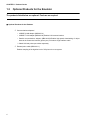
■ Optional Products for the Emulator
❍ Communications adaptors*
•
10BASE-2 LAN adaptor (MB2142-01)
•
10BASE-T LAN adaptor (MB2142-02):Enables LAN communications.
•
Parallel communications adaptor (MB2142-03):Enables high-speed downloading of object
data via the Centronics interface (printer port). Includes a single interface cable.
*: Obtain LAN and printer port cables separately.
❍ External probe cable (MB2142-11)
Enables sampling of the high/low level of I/O pins on the user system.
4
1.3 Main Unit (MB2141A) Summary
1.3
Main Unit (MB2141A) Summary
The main unit controls the emulation pod.
Note that the main unit cannot be used as an emulator on its own.
■ External Appearance of the Main Unit
Figure 1.3-1 "External Appearance of the Main Unit" shows the external appearance of the main
unit.
Figure 1.3-1 External Appearance of the Main Unit
MB 2 1 4 1
READY
POWER
ERROR
D
B
C
A
5
CHAPTER 1 Product Checks
1.3.1
Names of the Main Unit Components (Front Panel)
Figure 1.3-2 "Front Panel of the Main Unit" shows the front panel of the main unit.
■ Names of the Main Unit Components (Front Panel)
Figure 1.3-2 Front Panel of the Main Unit
Ready LED
Power LED
Hardware Error LED
MB 2141
READY POWER ERROR
D
B
C
A
Connectors for pod interface cables A to D
Connectors for pod interface cables A to D: Connectors used to connect the emulation pod.
Note that connector D is for future use and is not
used by the F2MC-16 series emulation pod.
6
Ready LED:
Illuminates when the communication link between
the main unit and host computer is established.
Power LED:
Illuminates when the power is turned on.
Hardware error LED:
Illuminates if a fault occurs in the emulator
hardware.
1.3 Main Unit (MB2141A) Summary
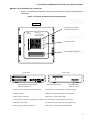
1.3.2
Names of the Main Unit Components (Rear Panel)
Figure 1.3-3 "Rear Panel of the Main Unit" shows the rear panel of the main unit.
■ Names of the Main Unit Components (Rear Panel)
Figure 1.3-3 Rear Panel of the Main Unit
Reset switch
External trigger
output connector
RESET
TRIG
External EMUL
output connector
EMUL
Power switch
MAIN UNIT
TFC MB2141 AM WONHGFD
ACRTT IM XXX
MBH K GRT
FUJITSU LIMITED
HFV
A 0123456789
B 0123456789
C 0123456789
POWER
I
O
RS - 232C
AC IN
COM PORT
F92100001
RS-232C connector
Connector for the
communications adaptor
Power supply socket
Reset switch:
The system reset switch. Pressing this switch
initializes the emulator main unit and MCU.
External trigger output connector:
Connector for connecting external measurement
equipment (such as a logic analyzer). The emulator
outputs an "H" (CMOS level) level for the duration of
one bus cycle when the emulator event trigger
conditions are satisfied. The signal can be used, for
example, to synchronize external measurement
equipment with the emulator.
External EMUL output connector:
Connector for connecting external measurement
equipment (such as a logic analyzer). The emulator
outputs an "H" (CMOS level) level while the MCU is
executing. The signal can be connected to a logic
analyzer or other measurement equipment to mask
sampling of the bus state while the MCU is halted
(when an "L" level is output), for example.
Power switch:
Switch for turning the power supply on or off.
Set to the "1" side to turn on and to the "0" side to
turn off.
RS-232C connector:
Connector for the RS-232C cable.
Connector for the communications adaptor: Connector for the communications adaptor.
Connect the LAN adaptor or parallel communications
adaptor.
Power supply socket:
Plug the AC power cable into this socket.
7
CHAPTER 1 Product Checks
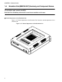
1.4
Emulation Pod (MB2145-507) Summary and Component Names
The emulation pod controls the MCU.
Note that the emulation pod cannot be used as an emulator on its own.
■ External Appearance of the Emulation Pod
Figure 1.4-1 "External Appearance of the Emulation Pod" shows the external appearance of the
emulation pod.
Figure 1.4-1 External Appearance of the Emulation Pod
21
B
M
FM
2
C-1
6
45
07
-5
SE
RIE
SE
MU
PO
EXE
C
HO
SLE LD
STO EP
P
RES
ET
8
L AT
WE
R
ION
PO
D
1.4 Emulation Pod (MB2145-507) Summary and Component Names
■ Names of the Emulation Pod Components
Figure 1.4-2 "Names of the Emulation Pod Components" shows the names of the emulation pod
components.
Figure 1.4-2 Names of the Emulation Pod Components
Top view
Socket for mounting
the evaluation MCU
MB2145-507
F2MC-16 SERIES
EMULATION POD
POWER
EXEC
Condition LED
HOLD
SLEEP
STOP
RESET
Probe cable connector
Front view
Front view
B
A
C
Connectors for the main unit
interface cables × 3
Expansion connector
External probe
cable connecto
Socket for mounting the evaluation MCU:
The socket for mounting the evaluation MCU.
Condition LED:
Indicates the operating status of the MCU.
Probe cable connector:
Connector for the probe cable
Connectors for the main unit interface cables: Connectors for connecting the main unit
Expansion connector:
An expansion connector. Not normally used.
External probe cable connector:
Connector for the external probe cable
9
CHAPTER 1 Product Checks
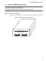
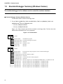
1.5
Emulator-Debugger Summary (Windows Version)
The emulator-debugger is the software used to control the emulator hardware.
■ Emulator-Debugger Summary (Windows Version)
The Windows version consists of two floppy disks.
❍ For the F2MC-16 (MB90700), F2MC-16H (MB90700H), F2MC-16L (MB90600), F2MC-16LX
(MB90500),and F2MC-16F (MB90200) series
•
3.5 inch (1.2MB)SP3407H004
•
3.5 inch (1.44MB)SP3507H004
Figure 1.5-1 "Disk Contents" lists the files contained on the floppy disks. The files other than
SETUP.EXE and EML907W.TXT are compressed.
Figure 1.5-1 Disk Contents
DISK1
SETUP.EXE
Installation program
EML907W.EXE
Emulator-debugger program
EML907W.HLP
Help file
ELM907W.TXT
Release notes
SPIN.VBX
VBX file
GRID.VBX
VBX file
DISK2
EINS16.EXE
Environment setup program for the emulator-debugger
EINS16.HLP
Help file
LOADERW.EXE Monitor program loader
LOADERW.HLP Help file
10
LANINSW.EXE
LAN environment setup program
LANINSW.HLP
Help file
EML907A.HEX
Monitor program (for the MB90700/MB90700H) : for MB2145-506
EML906.HEX
Monitor program (for the MB90600) : for MB2145-506
EML902.HEX
Monitor program (for the MB90200) : for MB2145-506
EML905.HEX
Monitor program (for the MB90500) : for MB2145-507
EML906.HEX
Monitor program (for the MB90600) : for MB2145-507
EML902.HEX
Monitor program (for the MB90200) : for MB2145-507
1.6 Probe Cable (MB2132-4XX) Summary
1.6
Probe Cable (MB2132-4XX) Summary
Various probe cables are available to suit the different MCU packages. Select the probe
cable for the package you are using
■ Probe Cable (MB2132-4XX) Summary
Table 1.6-1 "Probe Cable Part Numbers" lists the part numbers for the probe cables.
Table 1.6-1 Probe Cable Part Numbers
Package
Probe Cable
Part Numbers
SH-DIP-64
MB90660 Series SH-DIP64 probe cable
MB2132-433
QFP-64
MB2132-433 + conversion adapter
(manufactured by San Hayato)
MB2132-433,
64SD-64QF2-8L
QFP-80
QFP-80 probe cable 14 x 20 type
MB2132-454
SQFP-80
SQFP-80 probe cable (TQPACK version)
MB2132-444
QFP-100
QFP-100 probe cable
MB2132-457
QFP-100 probe cable (NQPACK version)
MB2132-464
SQFP-100
MB2132-457 + conversion adapter
(manufactured by San Hayato)
MB2132-457,
100QF-100SQF-16F
QFP-120
QFP-120 probe cable
MB2132-458
SQFP-120
SQFP-120 probe cable (TQPACK version)
MB2132-448
SQFP-120 probe cable (NQPACK version)
MB2132-468
LQFP-120 probe cable (NQPACK version)
MB2132-498
LQFP-120
*:The IC socket required for connection to a user system is attached to each cable.
The conversion adapter must be purchased as a separate item.
11
CHAPTER 1 Product Checks
1.6.1
Probe Cable External Appearance
Figure 1.6-1 "IC Socket-Type (QFP Type) Probe Cable" to 1.Figure 1.6-4 "TQPACK-Type
Probe Cable" show the external appearance of the probe cables for each package type.
■ Probe Cable External Appearance
Figure 1.6-1 "IC Socket-Type (QFP Type) Probe Cable" shows an IC socket type (QFP type)
probe cable.
Figure 1.6-1 IC Socket-Type (QFP Type) Probe Cable
*:Corresponding probe cables: MB2132-454, MB2132-457
Figure 1.6-2 "IC Socket-Type (DIP Type) Probe Cable" shows an IC socket type (DIP type)
probe cable.
Figure 1.6-2 IC Socket-Type (DIP Type) Probe Cable
*:Corresponding
probe cable:
MB2132-433
Figure 1.6-3 "NQPACK-Type Probe Cable" shows an NQPACK type probe cable.
12
1.6 Probe Cable (MB2132-4XX) Summary
Figure 1.6-3 NQPACK-Type Probe Cable
*:Corresponding probe cables: MB2132-464, MB2132-468, MB2132-498
Figure 1.6-4 "TQPACK-Type Probe Cable" shows a TQPACK type probe cable.
Figure 1.6-4 TQPACK-Type Probe Cable
*:Corresponding probe cables: MB2132-444, MB2132-448
13
CHAPTER 1 Product Checks
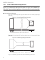
1.7
LAN Adaptor (MB2142-01/02) Summary and Component Names
Using the LAN adaptor to connect the emulator to a network containing the host
computer enables the emulator to communicate with the host computer via the LAN.
LAN adaptors are available for 10BASE-2 (MB2142-01) and 10BASE-T (MB2142-02).
■ External Appearance of the LAN Adaptors
Figure 1.7-1 "External Appearance of the LAN Adaptors" shows the external appearance of the
LAN adaptors.
Figure 1.7-1 External Appearance of the LAN Adaptors
AYJ
AYJ
LAN ADAPTOR
10BASE-T
LAN ADAPTOR
CON PORT
CON PORT
10BASE-2 adaptor
10BASE-T adaptor
■ Names of the LAN Adaptor Components
Figure 1.7-2 "Rear View of the LAN Adaptor" shows the rear view and Figure 1.7-3 "Front View
of the LAN Adaptor" shows the front view of the LAN Adaptor.
Figure 1.7-2 Rear View of the LAN Adaptor
LAN connector for coaxial
cable(for 10BASE-2)
LAN connector for twisted
pair cable(for 10BASE-T)
Figure 1.7-3 Front View of the LAN Adaptor
Interface connector
Interface connector: Connects to the main unit
14
1.8 Parallel Communications Adaptor (MB2142-03) Summary and Component Names
1.8
Parallel Communications Adaptor (MB2142-03) Summary
and Component Names
Using the parallel communications adaptor (MB2142-03) to connect the emulator to the
host computer enables the emulator to communicate with the host computer using
parallel communications.
■ External Appearance of the Parallel Communications Adaptor
Figure 1.8-1 "External Appearance of the Parallel Communications Adaptor" shows the external
appearance of the parallel communications adaptor.
Figure 1.8-1 External Appearance of the Parallel Communications Adaptor
INWNV
PARALLEL
COMMUNICATION
ADAPTOR
CON PORT
■ Names of the Parallel Communications Adaptor Components
Figure 1.8-2 "Front and Rear Views of the Parallel Communications Adaptor" shows the front
and rear views of the parallel communications adaptor.
Figure 1.8-2 Front and Rear Views of the Parallel Communications Adaptor
Parallel communications connector
Rear view
Interface connector
Front view
Parallel communications connector:Connects to the host compurer
Interface connector:
Connects to the main unit
15
CHAPTER 1 Product Checks
1.9
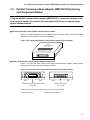
External Probe Cable (MB2142-11) Summary
The external probe cable (MB2142-11) enables sampling of the high/low level of I/O
pins on the user system.
The probe also enables external signals to be used as event trigger conditions.
■ External Appearance of the External Probe Cable
Figure 1.9-1 "External Appearance of the External Probe Cable" shows the external appearance
of the external probe cable.
Figure 1.9-1 External Appearance of the External Probe Cable
CMK
CK
OXN
OMS
16
CHAPTER 2
Hardware Setup
This chapter describes how to connect the MB2140 to the host computer and user
system.
2.1 System Structure (Basic Structure)
2.2 System Structure (Optional Connections)
2.3 Connecting the Host Computer and Main Unit
2.4 Connecting the Main Unit and Emulation Pod
2.5 Setting Up the Emulation Pod
2.6 Connecting the Emulation Pod and User System
2.7 Connecting Options (Communications Adaptors)
2.8 Connecting Options (External Probe Cable)
17
CHAPTER 2 Hardware Setup
2.1
System Structure (Basic Structure)
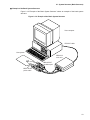
Figure 2.1-1 "Outline of the System Structure" shows an outline of the basic structure
of the system. The figure shows the minimum configuration for using the emulator.
■ System Structure (Basic Structure)
Figure 2.1-1 Outline of the System Structure
Host computer
RS-232C
cable
MB2141A
main unit
I/F cable
MB2145-507
emulation pod
Probe cable
User system
18
2.1 System Structure (Basic Structure)
■ Example of the Basic System Structure
Figure 2.1-2 "Example of the Basic System Structure" shows an example of the basic system
structure.
Figure 2.1-2 Example of the Basic System Structure
Host computer
RS-232C cable
User system
MB2141A
main unit
MB2145-507
emulation pod
0
MB
21
41
1
MB2132-4XX
probe cable
3
4
19
CHAPTER 2 Hardware Setup
2.2
System Structure (Optional Connections)
Figure 2.2-1 "Outline of the Optional Connections" shows an outline of the optional
connections. The items inside the dotted line in the figure are options. Purchase the
options as required.
■ System Structure (Optional Connections)
Figure 2.2-1 Outline of the Optional Connections
To LAN or
printer
connector
Host computer
RS-232C
cable
I/F cable
LAN adaptor or
parallel
communications
adaptor
MB2141A
main unit
MB2145-507
emulation pod
Probe cable
Coaxial cable
Measurement
equipment, etc.
20
I/F cable
User system
External probe
cable
2.3 Connecting the Host Computer and Main Unit
2.3
Connecting the Host Computer and Main Unit
Use an RS-232C cable (straight-through type) to connect the host computer and main
unit.
■ Connecting the Host Computer and Main Unit
Figure 2.3-1 "Connection Between the Host Computer and Main Unit" shows the connection
between the host computer and main unit. The RS-232C cable used for the connection is a
straight-through type.
Table 2.3-1 "RS-232C Cables for Different PCs" lists the three types of RS-232C cable that are
available from Fujitsu to suit different host computers (RS-232C connector shape).
Figure 2.3-1 Connection Between the Host Computer and Main Unit
Rear panel of host computer
Rear panel of main unit
Table 2.3-1 RS-232C Cables for Different PCs
PC Type
Part Number
Cable Specifications
FMR Series
PC-9800 Series
MB2124-03
D-SUB male 25-pin/male 25-pin
IBM-PC/XT
MB2124-04
D-SUB male 25-pin/female 25-pin
FMV Series
IBM-PC/AT
MB2124-05
D-SUB male 25-pin/female 9-pin
21
CHAPTER 2 Hardware Setup
2.4
Connecting the Main Unit and Emulation Pod
The main unit and emulation pod are connected by three interface cables.
■ Connecting the Main Unit and Emulation Pod
Figure 2.4-1 "Connection Between the Main Unit and Emulation Pod" shows the connection
between the main unit and emulation pod.
Guides are provided to prevent insertion of pod interface cables A, B, and C into the incorrect
connectors on the main unit or emulation pod.
Before connecting the cables, check that the letter (A, B, or C) on the cable matches the letter
on the main unit and emulation pod connectors.
The connectors on the main unit and emulation pod have a locking mechanism that engages
when the cable is connected. Always insert the cables firmly until the lock engages.
Similarly, press the lock levers on each side of the pod interface cable connectors when
disconnecting the cables.
Figure 2.4-1 Connection Between the Main Unit and Emulation Pod
Rear panel of the emulation pod
Front panel of the main unit
M
RE
D
P
M
O
B
2
2
M 14
C 5
-1 -5
6 0
S 7
E
R
IE
S
ST
T
F
SE
S
L
E
O
P
H
E
E
LD
C
RE
B2
AD
Y
14
PO
1
WE
R
X
E
ER
C
EM
UL
AT
IO
N
R
E
W
O
P
RO
R
PO
D
B
A
22
2.5 Setting Up the Emulation Pod
2.5
Setting Up the Emulation Pod
The emulation pod requires the following setup.
• Mounting the crystal for the MCU clock
• Mounting the evaluation MCU
■ Setting Up the Emulation Pod
❍ Mounting the crystal for the MCU clock
As the oscillation from the crystal mounted on the user system is not available, an equivalent
crystal and capacitor must be mounted in the crystal area of the emulation pod and a DIP switch
set.
❍ Mounting the evaluation MCU
Mount the evaluation MCU in the IC socket. Evaluation MCUs are available for each series.
23
CHAPTER 2 Hardware Setup
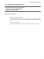
2.5.1
MCU Clock Supply
To supply the MCU clock, install a crystal oscillator and capacitors in the crystal
assemble socket (SC3) on the top of the emulation pod.
Select the clock supply method with the clock switching switch (SW1) and subclock
switching jumper (S1).
■ MCU Clock Supply
Figure 2.5-1 "each part" shows each part.
Figure 2.5-1 each part
Clock supply switching switch
Crystal oscillator installation socket
Top of the emulation pod
24
Subclock switching jumper
2.5 Setting Up the Emulation Pod
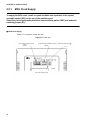
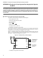
2.5.2
Clock Circuit
Figure 2.5-2 "Clock and Peripheral Circuits" shows the circuit diagram of the clock
circuit.
■ Clock Circuit
Figure 2.5-2 Clock and Peripheral Circuits
Evaluation
25
CHAPTER 2 Hardware Setup
2.5.3
Clock Circuit
Table 2.5-1 "Clock Selection Switch (SW1) Settings" shows how to set the clock
switching switch (SW1) and jumper (S1).
■ Clock Circuit
Table 2.5-1 Clock Selection Switch (SW1) Settings
Clock Supply Type
SW1 setting
S1 setting
Remarks
Main clock
Sub-clock
1
2
3
4
Crystal area
Supplied
OFF
OFF
OFF
OFF
Connect B1 and C1,
and B2 and C2
*1
Not supplied
OFF
OFF
ON
ON
Connect A1 and B1,
and A2 and B2
*3
Supplied
ON
ON
OFF
OFF
Connect B1 and C1,
and B2 and C2
*1, *2
Not supplied
ON
ON
ON
ON
Connect A1 and B1,
and A2 and B2
*2, *3
User system
*1:The sub-clock uses the 32.768KHz crystal in the emulation pod.
*2:Oscillation in which a crystal oscillator is installed in the user system is not supported.To supply the
clock from the user system, provide an oscillation circuit in the user system and supply the clock
through the CMOS buffer or with a similar circuit.
*3:Always use this setting for MCUs that do not have a sub-clock.
26
2.5 Setting Up the Emulation Pod
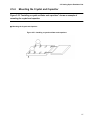
2.5.4
Mounting the Crystal and Capacitor
Figure 2.5-3 "Installing a crystal oscillator and capacitors" shows an example of
mounting the crystal and capacitor.
■ Mounting the Crystal and Capacitor
Figure 2.5-3 Installing a crystal oscillator and capacitors
27
CHAPTER 2 Hardware Setup
2.5.5
Power Supply to the Evaluation MCU
Power is supplied to the evaluation MCU with the power supply switching jumper (S2).
■ Power Supply to the Evaluation MCU
Figure 2.5-4 "individual parts" shows the individual parts.
Figure 2.5-4 individual parts
Power supply switching jumper
Emulation pod top
28
2.5 Setting Up the Emulation Pod
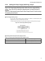
2.5.6
Setting the Power Supply Switching Jumper
Figure 2.5-5 "Power Supply Switching Jumper" shows the power supply switching
jumper. Table 2.5.6a lists the settings for supplying power used specifically by the
emulator.
Table 2.5-2 "Switching the Emulator-Specific Power Supply Terminal" lists the settings
for supplying user port power.
■ Power Supply Switching Jumper
Set the power supply switching jumper depending on whether an emulator-specific power
supply terminal (*1) of the evaluation MCU is provided.
*1:Ask the Fujitsu Sales Division for product types having an emulator-specific power supply.
Figure 2.5-5 Power Supply Switching Jumper
*1 : Power supply switching jumper for user port 0
*2 : Power supply switching jumper for user port 1
*3 : Switching jumper for emulator-specific power supply terminal
■ Switching the Emulator-Specific Power Supply Terminal
Table 2.5-2 Switching the Emulator-Specific Power Supply Terminal
Emulator-specific power supply terminal
S2 setting
Installed
Connect B and C (+5 V side)
Not installed
Connect A and B (UVCC1 side)
29
CHAPTER 2 Hardware Setup
■ Switching the User Port Power Supply
Set the port power supply switching jumper for the appropriate user port power supply (*1) if the
evaluation MCU has the two-system user power supply terminal.
*1: Only user ports 0 and 1 are supported.
Table 2.5-3 Jumper Setting for Switching the User Port Power Supply
User power
supply system
S2 setting
Port 0 switching jumper (*1)
Port 1 switching jumper (*1)
System 1
Connect A and B (UVCC1 side)
Connect A and B (UVCC1 side)
System 2
Connect on the power supply side
(*2)
Connect on the power supply side
(*2)
*1: See Figure 2.5-5 "Power Supply Switching Jumper" for the jumper terminal positions.
*2: Connect on the VCC side for the port power supply.
Example: The power supply for port 0 is UVCC1, and that for port 1 is UVCC2.
Port 0 switching jumper Connect A and B (UVCC1 side)
Port 1 switching jumper Connect B and C (UVCC2 side)
30
2.5 Setting Up the Emulation Pod
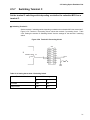
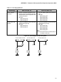
2.5.7
Switching Terminal C
Set the terminal C switching switch depending on whether the evaluation MCU has a
terminal C.
■ Switching Terminal C
Set the terminal C switching switch depending on whether the evaluation MCU has a terminal C.
Figure 2.5-6 "Terminal C Processing Circuit" shows the terminal C processing circuit. Table
2.5-4 "Setting the terminal C Switching Switch" lists the settings for the terminal C switching
switch.
Figure 2.5-6 Terminal C Processing Circuit
SW1
SW1
Evaluation MCU
P70/C
110
P70
0.1
50
GND
Table 2.5-4 Setting the terminal C Switching Switch
Terminal C function
SW1 setting
5
6
Provided
OFF
ON
Not provided
ON
OFF
31
CHAPTER 2 Hardware Setup
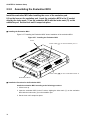
2.5.8
Assembling the Evaluation MCU
Install the evaluation MCU after installing the cover of the emulation pod.
Lift up the lever on the emulation pod. Insert the evaluation MCU in the IC socket,
aligning the index mark (*1) on the evaluation MCU with the index mark (*2) on the
emulation pod. Set the lever until it snaps into place.
■ Installing the Evaluation MCU
Figure 2.5-7 "Installing the Evaluation MCU" shows installation of the evaluation MCU.
Figure 2.5-7 Installing the Evaluation MCU
Lever
Index mark (
21
B
M
FM
2
C-1
6
) on the emulation pod *1
45
07
-5
SER
IES
E
MU
L AT
ION
PO
D
PO
EXE WER
C
HO
SLE LD
EP
STO
P
RES
ET
Index mark (
) on the evaluation MCU *2
Evaluation MCU
■ Installation Procedure for the Evaluation MCU
Install the evaluation MCU according to the following procedure.
1. Lift the lever up.
2. Insert the evaluation MCU in the IC socket, aligning the index mark (*1) on the evaluation
MCU with the index mark (*2) on the emulation pod.
3. Set the lever until it snaps into place.
32
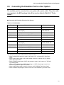
2.6 Connecting the Emulation Pod to a User System
2.6
Connecting the Emulation Pod to a User System
The emulation pod is connected to a user system with a probe cable. The probe cable
corresponds to the MCU package that will be used, as listed in Table 2.6-1 "Probe
Cables".
■ Connecting the Emulation Pod and a User System
Table 2.6-1 Probe Cables
Package
Probe cable name
Probe cable type
SH-DIP-64
MB90660 Series SH-DIP64 probe cable
MB2132-433
QFP-64
MB2132-433 + conversion adapter (manufactured
by San Hayato)
MB2132-433,
64SD-64QF2-8L
QFP-80
QFP-80 probe cable 14 x 20 type
MB2132-454
SQFP-80
SQFP-80 probe cable (TQPACK version)
MB2132-444
QFP-100
QFP-100 probe cable
MB2132-457
QFP-100 probe cable (NQPACK version)
MB2132-464
SQFP-100
MB2132-457 + conversion adapter (manufactured
by San Hayato)
MB2132-457,
100QF-100SQF-16F
QFP-120
QFP-120 probe cable
MB2132-458
SQFP-120
SQFP-120 probe cable (TQPACK version)
MB2132-448
SQFP-120 probe cable (NQPACK version)
MB2132-468
LQFP-120 probe cable (NQPACK version)
MB2132-498
LQFP-120
The method of connection to a user system depends on the probe cable that will be used. See
the description of the probe cable that will be used for setup.
• When the SH-DIP-64 package is used:Go to Section 2.6.1 "IC Socket (DIP) Type Probe
Cable".
• When the QFP-80 package or QFP-100 package is used:Go to Section 2.6.2 "IC Socket
(QFP) Type Probe Cable".
• When the SQFP-80 package or SQFP-120 package is used:Go to Section2.6.3 "TQPACK
Type Probe Cable".
• When the QFP-100 package, SQFP-120 package, or LQFP-120 package is used:Go to
Section2.6.4 "NQPACK Type Probe Cable"..
• When the QFP-64 package is used:Go to Section 2.6.5 "NQPACK Type Probe Cable".
• When the SQFP-100 package is used:Go to Section 2.6.6 "NQPACK Type Probe Cable"
33
CHAPTER 2 Hardware Setup
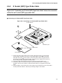
2.6.1
IC Socket (DIP) Type Probe Cable
Figure 2.6.1a shows the connection method of an IC socket (DIP) type probe cable.
■ Connecting an IC Socket (DIP) Type Probe Cable
Figure 2.6-1 Connecting an IC Socket Type (DIP) Probe Cable
Probe cable*3
S
07 IE
-5 ER
45 S
21 6
B -1
M C
2M
F
EM
*2
PO
EX
HO
SL
ST
RE
SE
OP
EE
EC
UL
WE
AT
ION
PO
D
R
LD
P
T
*1
Emulation pod
Index
User system
*1: Fully insert the probe cable into the socket, aligning the index (semicircular notch mark) at the end
of the probe cable with the index (semicircular notch) on the socket.
*2: Insert the probe cable into the connector on the top of the emulation pod.
*3: The probe cable is not flexible enough to handle horizontal stress. Arrange the emulation pod and
user system so that excessive stress is not applied to the probe cable.
34
2.6 Connecting the Emulation Pod to a User System
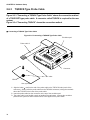
2.6.2
IC Socket (QFP) Type Probe Cable
Figure 2.6-2 "Connecting an IC Socket (QFP) Type Probe Cable" shows the connection
method for an IC socket (QFP) type probe cable.
■ Connecting an IC Socket (QFP) Type Probe Cable
Figure 2.6-2 Connecting an IC Socket (QFP) Type Probe Cable
Probe cable*3
21
B
M
FM
2
45
6S
ER
IES
E
07
-5
C -1
MU
*2
RE
ST
SE
SL
OP
HO
EE
EX
LD
PO
EC
L AT
WE
ION
PO
D
R
P
T
*1
Emulation pod
Index
User system
*1 : Gently insert the probe cable into the socket, aligning the index ( ) mark etched
on the position indicted by the arrow in the above figure) at the end of the probe
cable with the index ( ) on the socket. Secure the probe cable, using the screws
and washers attached to the probe cable. Be careful not to tighten the screws too
much. Doing so will damage the socket threads.
*2 : Insert the probe cable into the connector on the top of the emulation pod.
*3 : The probe cable is not flexible enough to handle horizontal stress. Arrange the
emulation pod and user system so that excessive stress is not applied to the probe
cable.
*4 : The foot pattern of the socket of the user system may be different from the foot pattern
of mass production MCUs. Note this point during design of PC boards.
35
CHAPTER 2 Hardware Setup
2.6.3
TQPACK Type Probe Cable
Figure 2.6-3 "Connecting a TQPACK Type Probe Cable" shows the connection method
of a TQSOCKET type probe cable. A connector called TQPACK is required for the user
system.
Figure 2.6-4 "Connecting TQPACK" shows the connection method.
■ Connecting a TQPACK Type Probe Cable
Figure 2.6-3 Connecting a TQPACK Type Probe Cable
Emulation pod
Probe cable*3
21
B
M
FM
2
45
6S
ER
IES
07
-5
C -1
HO
LD
ST
OP
RE
SE
T
EM
EX
EC
UL
AT
ION
PO
D
PO
WE
R
SL
EE
P
Connector
Index
QPACK
User system
*1: Align the index ( mark) at the end of the probe cable to the TQPACK index (notch of the
connector). Gently insert the probe cable into the TQPACK connector, locking the terminals
above the TQPACK in the holes of the probe cable.
*2: Insert the probe cable into the connector on the top of the emulation pod.
*3: The probe cable is not flexible enough to handle horizontal stress. Arrange the emulation
pod and user system so that excessive stress is not applied to the probe cable.
36
2.6 Connecting the Emulation Pod to a User System
■ Connecting TQPACK
Figure 2.6-4 Connecting TQPACK
Screw hole
Header section
TQSOCKET*1
Enameled set screw*2
TQPACK* 3
User system
*1: It is very difficult to replace the TQPACK. Be sure to use it with the TQPACK.
*2: Put the enameled set screw attached to the TQPACK in the TQSOCKET. Then, connect
the TQSOCKET to the TQPACK.
*3: Compared to mass production MCUs, the part of the TQPACK that contacts the PC board
(flat part at the top of a terminal) may have a different size. Take this point into
consideration when designing the pattern on a PC board.
*4: The probe cable is not flexible enough to handle horizontal stress. Arrange the emulation
pod and user system so that excessive stress is not applied to the probe cable.
■ Removing the Probe Cable
Tighten the machine screw attached to the probe cable from the header part. The machine
screw touches the enameled set screw, thereby loosing the connector of the probe cable.
Remove the probe cable after it is completely loose. If the probe cable cannot be removed with
the above method, raise the probe cable from all four sides, using a small flat-blade screw driver
or similar object.
37
CHAPTER 2 Hardware Setup
2.6.4
NQPACK Type Probe Cable
Figure 2.6-5 "Connecting NQPACK" shows the connection method of an NQSOCKET
type probe cable. A connector called NQPACK is required for the user system.
Figure 2.6-6 "Details of NQPACK Connection" shows the connection method.
■ Connecting an NQPACK Type Probe Cable
Figure 2.6-5 Connecting NQPACK
Probe cable*3
S
07 IE
-5 R
45 SE
21 6
B -1
M C
2M
F
ST
OP
RE
SE
T
HO
LD
SL
EE
P
EX
EC
EM
UL A
TIO
NP
OD
PO
WE
R
*1
Emulation pod
Index
*4
User system
*1: Align the index ( mark) at the end of the probe cable with the YQPACK index (notch
of the connector). Secure the probe cable, using the four screws and washers attached
to the probe cable.
*2: Insert the probe cable into the connector on the top of the emulation pod.
*3: The probe cable is not flexible enough to handle horizontal stress. Arrange the
emulation pod and user system so that excessive stress is not applied to the probe
cable.
*4: The foot pattern of the YQPACK of the user system may be different from the foot
pattern of mass production MCUs. Note this point during design of PC boards.
38
2.6 Connecting the Emulation Pod to a User System
■ Connecting NQPACK
Figure 2.6-6 Details of NQPACK Connection
Screw
Header part
YQPACK
NQPACK*1
User system
39
CHAPTER 2 Hardware Setup
2.6.5
Probe Cable of the Conversion Adapter Type (DIP[***]QFP)
Figure 2.6-7 "Connecting a Conversion Adapter Type (from DIP to QFP) Probe Cable"
shows the connection method for the conversion adapter type (from DIP to QFP) probe
cable.
■ Connecting a Conversion Adapter Type (from DIP to QFP) Probe Cable
Figure 2.6-7 Connecting a Conversion Adapter Type (from DIP to QFP) Probe Cable
Probe cable*3
S
07 IE
-5 ER
45 S
21 6
B -1
M C
2M
F
*2
EM
UL
PO
EX
HO
SL
ST
RE
SE
OP
EE
EC
AT
WE
ION
PO
D
R
LD
P
T
*1
Emulation pod
Index
User system
Conversion adaptor*4
*1: Firmly insert the probe cable into the socket, aligning the index (semicircular notch mark)
at the end of the probe cable with the index (semicircular notch) on the socket.
*2: Insert the probe cable into the connector on the top of the emulation pod.
*3: The probe cable is not flexible enough to handle horizontal stress. Arrange the emulation
pod and user system so that excessive stress is not applied to the probe cable.
*4: The foot pattern of the conversion adapter may be different from the foot pattern of mass
production MCUs. Note this point during design of PC boards.
40
2.6 Connecting the Emulation Pod to a User System
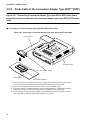
2.6.6
Conversion Adapter Type (QFP[***]SQFP) Probe Cable
Figure 2.6-8 "Connecting a Conversion Adapter Type (from QFP to SQFP) Probe
Cable" shows the connection method for a conversion adapter type (from QFP to
SQFP) probe cable.
■ Connecting a Conversion Adapter Type (from QFP to SQFP) probe cable
Figure 2.6-8 Connecting a Conversion Adapter Type (from QFP to SQFP) Probe Cable
Probe cable*3
For QFP-100 (two screws)
S
07 IE
-5 ER
45 S
21 6
B -1
M C
2M
F
*2
EM
UL A
TIO
NP
OD
R
E
W
O
P
C
E
X
E
LD
O
H EP
LE
S
P
O
T
T
E
S
E
R
S
*1
Emulation pod
Index
User system
Conversion adapter *4
*1: Gently insert the probe cable into socket, aligning the index ( mark etched at the
location indicated by the arrow in the above figure) at the end of the probe with the
index ( ) on the socket. Secure the probe cable, using the screws and washers
attached to the probe cable. Be careful not to tighten the screws too much. Doing
so will damage the socket threads.
*2: Insert the probe cable into the connector on the top of the emulation pod.
*3: The probe cable is not flexible enough to handle horizontal stress. Arrange the
emulation pod and user system so that excessive stress is not applied to the probe
cable.
*4: The foot pattern of the conversion adapter may be different from the foot pattern of
mass production MCUs. Note this point during design of PC boards.
41
CHAPTER 2 Hardware Setup
2.7
Connecting Options (Communications Adaptors)
The parallel communications adaptor is used in addition to the RS-232C link.
Therefore, always connect the RS-232C cable between the host computer and main
unit.
The connector used to connect the communications adaptor and emulation pod has a
locking mechanism that engages when the cable is connected. Always insert the cable
firmly until the lock engages.
Similarly, when disconnecting the communications adaptor interface cable, press the
lock levers on each side of the cable connectors.
■ Connecting a Communications Adaptor
Figure 2.7-1 Connecting a Communications Adaptor
LAN adaptor (front)
R
TO
AP
N
LA
AD
R
TO
AP
N AD
LA
Figure 2.7-1 "Connecting a Communications Adaptor" shows the connection between the main
unit and communications adaptor. The example shown in the figure is for a LAN connection.
The next setup step depends on whether or not an external probe cable is used, as follows.
42
•
External probe cable not used:Proceed to “Chapter 3 "Software Setup".
•
External probe cable used:Proceed to “Section2.8 "Connecting Options (External Probe
Cable)".
2.8 Connecting Options (External Probe Cable)
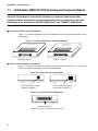
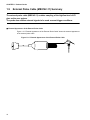
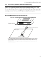
2.8
Connecting Options (External Probe Cable)
Figure 2.8-1 "Connection Between External Probe Cable and Emulation Pod" shows
the connection between the external probe cable and emulation pod.When connecting
an external probe cable to the user system, check the signal names on the label on the
external probe cable and connect the IC clips securely to the user system.
■ Connection Between External Probe Cable and Emulation Pod
Figure 2.8-1 Connection Between External Probe Cable and Emulation Pod
Emulation pod (front)
*
External probe cable connector
User system
*: The connector used to connect the external probe cable to the emulation pod has a locking
mechanism that engages when the cable is connected. Always insert the cable firmly until
the lock engages.
Similarly, when disconnecting the external probe cable, press the lock levers on each side
of the cable connector.
43
CHAPTER 2 Hardware Setup
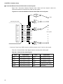
■ Connection Between External Probe Cable and User System
Figure 2.8-2 "Connection Between External Probe Cable and User System" shows the
connection between the external probe cable and user system.
Figure 2.8-2 Connection Between External Probe Cable and User System
*
GND
GND
*
CK
External probe cable
GND
Black
CK
Gray
CH7
Purple
CH7
CH6
Blue
CH6
CH5
Green
CH5
CH4
Yellow
CH4
CH3
Orange
CH3
CH2
Red
CH2
CH1
Brown
CH1
CH0
Black
User system
CH0
*: Note that IC clips for the GND wires have a different shape to the IC clips for other signals.
Table 2.8-1 "External Probe Cable Signals" lists the external probe cable signals.
Table 2.8-1 External Probe Cable Signals
Color
44
Signal Name
Color
Signal Name
Black
CH0 (Channel 0 input)
Green
CH5 (Channel 5 input)
Brown
CH1 (Channel 1 input)
Blue
CH6 (Channel 6 input)
Red
CH2 (Channel 2 input)
Purple
CH7 (Channel 7 input)
Orange
CH3 (Channel 3 input)
Gray
CK (External clock input)
Yellow
CH4 (Channel 4 input)
Black
GND (GND)
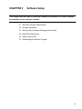
CHAPTER 3
Software Setup
This chapter describes how to setup the software environment on the host computer
and emulator so as to use the emulator.
3.1 RS-232C Interface Specifications
3.2 Program Installation
3.3 Setting Up the Emulator-Debugger Environment
3.4 Install File Setting Items
3.5 When Using a LAN
3.6 Downloading the Monitor Program
45
CHAPTER 3 Software Setup
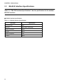
3.1
RS-232C Interface Specifications
Table 3.1-1 "RS-232C Interface Specifications" lists the specifications for the emulator
RS-232C interface.
■ RS-232C Interface Specifications
Table 3.1-1 RS-232C Interface Specifications
Parameter
Specification
Connection type
DCE
Baud rate
4800, 9600, 19200 [bps]
Number of data bits
8 bits
Parity bit
None
Number of stop bits
1 bit
X control
None
46
3.2 Program Installation
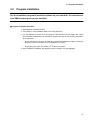
3.2
Program Installation
Use the installation program to install the software on your hard disk. You must have at
least 3MB of spare space on your hard disk.
■ Program Installation Procedure
1. Start Windows in enhanced mode.
2. Insert “DISK1” of the installation disks in the floppy disk drive.
3. Use File Manager or similar to run the program “SETUP.EXE” from the floppy disk. Follow
the instructions displayed by the installation program and specify the following information
when requested.
•
Specify the directory in which to install the program:The installation program creates the
directory if it does not already exist. The default is “C:\FTOOL”.
•
Specify the group name:The default is “F2C16series emulator”.
4. When installation completes, the specified group is created in Program Manager.
47
CHAPTER 3 Software Setup
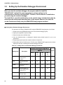
3.3
Setting Up the Emulator-Debugger Environment
When you start the emulator-debugger, the program reads the install file
"EML907A.INS" (default file name) and performs various settings for the
communications interface and target MCU. Therefore, this file must be created before
you start using the emulator-debugger.
The install file is a text file and therefore can be created using a standard text editor by
referring to the setting items described later in this manual. However, the install file
can be created more easily using the [EML907W Setup] program provided.
■ Setting Up the Emulator-Debugger Environment
The procedure for creating “EML907A.INS” using the [EML907W Setup] program is as follows.
1. Double click on the [EML907W Setup] icon in the emulator-debugger group.
2. Specify the target MCU in [Select Chip].
3. Select the setup item in [Select Item].
4. Click the [Details] button in [Settings].:A detailed setup window opens for you to set
parameters.
5. Repeat steps [3] and [4] for the required number of setup items.
6. Select [Save As] from the [File] menu.:The file name “EML907A.INS” appears as the default.
Specify the directory containing the emulator-debugger and save.
Table 3.3-1 Setting Items in the Emulator-Debugger Install File
Emulator debugger/target MCU
Setting Item
EML907A
Description
F2MC-16
48
F2MC-
F2MC-
F2MC-
16H
16L
16F
INTERFACE
Specifies the
communication
interface
T1
T1
T1
T1
CHIP
Specifies the target
MCU
T1
T1
T1
T1
INROM
Specifies the internal
ROM area
T2
T2
T2
T2
ROMIMAGE
Specifies whether an
internal ROM image is
present or not
—
—
T2
T2
BUSWIDTH
Specifies the external
data bus width
T2
T2
T2
T2
TYPE
Specifies the external
data bus type
—
T2
—
—
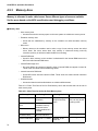
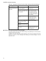
Remark
s
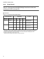
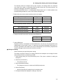
3.3 Setting Up the Emulator-Debugger Environment
Table 3.3-1 Setting Items in the Emulator-Debugger Install File
Emulator debugger/target MCU
Setting Item
EML907A
Description
2
F MC-16
2
F MC-
2
F MC-
2
F MC-
16H
16L
16F
Remark
s
IOMAX
Specifies the I/O area
—
—
—
—
*
RAM
Specifies the internal
RAM area
—
—
—
—
*
EXERAM
Specifies the internal
instruction RAM area
—
T3
—
—
PARALLEL
Specifies the parallel
port number
T3
T3
T3
T3
SPEED
Specifies the emulator
operation speed
—
—
—
—
TMP
Specifies the work
directory
T3
T3
T3
T3
NATIVE
CHECK
Specifies whether or
not command
restrictions apply
T3
T3
—
—
T1:The item must always be set.
T2:Items applicable to the MCU operation must always be set.
T3:The item must be set when required.
—:Setting not required.
* :Setting is required when using the MB2145-505 emulation pod.
49
CHAPTER 3 Software Setup
3.4
Install File Setting Items
This section describes the main install file setting items. Refer to the "EmulatorDebugger Manua" for further information about these and other setup items.
■ Install File Setting Items
– Communication interface setting (INTERFACE)
Specifies the interface between the host computer and emulator hardware.
– Chip type setting (CHIP)
Specifies whether debugging is being performed for an F2MC-16L, F2MC-16LX, F2MC-16/
16H, or F2MC-16F MCU.
– Internal ROM area setting (INROM)
Specifies the internal ROM area for MCUs that have internal ROM.
– Internal ROM image present or not setting (ROMIMAGE)
Specifies whether an internal ROM image is present or not.
– External data bus width setting (BUSWIDTH)
Specifies the width of the external data bus for MCUs that perform external access.
– External data bus type setting (TYPE)
Specifies the type of the external data bus. Only applies to F2MC-16H chips that have
internal instruction RAM.
– Internal instruction RAM area setting (EXERAM)
his setting is only required for F2MC-16H chips that have internal instruction RAM.
Ensure that settings related to the MCU specification, operating mode, and similar are set
correctly for the actual conditions. Emulation will not operate correctly if the settings do not
match the actual conditions.
50
•
[ ] :Parameters enclosed in brackets can be omitted.
•
{|} :Specify one of the parameters separated by |.
3.4 Install File Setting Items
3.4.1
Communication Interface Setting (INTERFACE)
Specifies the interface between the host computer and emulator hardware.
■ Communication Interface Setting (INTERFACE)
❍ When connecting via RS-232C
INTERFACE RS232C [port number [baud rate]]
If omitted, the port number defaults to zero (existing RS232C port). If the baud rate is omitted,
the optimum baud rate for the host computer is selected.
(Example) INTERFACE RS232C 0 9600
❍ When connecting via a LAN
INTERFACE LAN host name
(Example) INTERFACE LAN EML1001
51
CHAPTER 3 Software Setup
3.4.2
Chip Type Setting (CHIP)
Specifies whether debugging is being performed for an F2MC-16L,16LX, and 16/16H
■ Chip Type Setting (CHIP)
❍ When debugging an F2MC-16L
CHIP 16L
❍ When debugging an F2MC-16LX
CHIP 16LX
❍ When debugging an F2MC-16/16H
CHIP 16
❍ When debugging an F2MC-16F
CHIP 16F
52
3.4 Install File Setting Items
3.4.3
Internal ROM Area Setting (INROM)
Specifies the internal ROM area for MCUs that have internal ROM.
■ Internal ROM Area Setting (INROM)
INROM address range
Specify the address range for the internal ROM area as follows.
MCU ROM sizes such as 48KB or 96KB cannot be specified. Instead specify 64KB or 128KB
respectively.
Internal ROM Size
Address Range
4KB
FFF000..FFFFFF
8KB
FFE000..FFFFFF
16KB
FFC000..FFFFFF
32KB
FF8000..FFFFFF
64KB
FF0000..FFFFFF
128KB
FE0000..FFFFFF
(Example) INROM FF0000..FFFFFF
53
CHAPTER 3 Software Setup
3.4.4
Internal ROM Image Present or Not Setting (ROMIMAGE)
Specifies whether an internal ROM image is present or not.
■ Internal ROM Image Present or Not Setting (ROMIMAGE)
ROMIMAGE {ON|OFF}
Specify ON for MCUs that have an internal ROM image. Otherwise, specify OFF.
(Example) ROMIMAGE ON
54
3.4 Install File Setting Items
3.4.5
External Data Bus Width Setting (BUSWIDTH)
Specifies the width of the external data bus for MCUs that perform external access.
■ External Data Bus Width Setting (BUSWIDTH)
❍ For the F2MC-16F/16/16H
BUSWIDTH buswidth
Specify “8” for an 8-bit bus and “16” for a 16-bit bus.
(Example) BUSWIDTH 8
❍ For the F2MC-16L/16LX
BUSWIDTH buswidth [I/O bus width [HIGH bus width [LOW bus width]]]
For each bus width, specify “8” for an 8-bit bus and “16” for a 16-bit bus.
Always set the bus width used on the MCU.
(Example) BUSWIDTH 16 8 8 8
55
CHAPTER 3 Software Setup
3.4.6
External Data Bus Type Setting (TYPE)
Specifies the type of the external data bus. Only applies to F2MC-16H chips that have
internal instruction RAM.
■ External Data Bus Type Setting (TYPE)
TYPE {MULTI | NONMULTI | BHE | ALT}
56
•
MULTI:Specify when multiplex mode is used for the memory access mode in a single-chip
type system.
•
NONMULTI:Specify when non-multiplex mode is used for the memory access mode in a
single-chip type system.
•
BHE:Specify when BHE mode is used for the memory access mode in a host type system.
•
ALT:Specify when alternate write mode is used for the memory access mode in a host type
system.
3.4 Install File Setting Items
3.4.7
Internal Instruction RAM Area Setting (EXERAM)
This setting is only required for F2MC-16H chips that have internal instruction RAM.
■ Internal Instruction RAM Area Setting (EXERAM)
EXERAM read start address
write start address
size
[upper write address mask]
- Specify one of the following for the size parameter.
0100, 0200, 0400, 0800, 1000, 2000, 4000
- When using the upper 8 bits of the write address (A23 to A16) as ports, set an 8-bit mask
pattern as follows for the upper write address mask.
A23
A22
A21
A20
A19
MSB
A18
A17
A16
LSB
0: Use as a port
1: Use as an address
(Example) EXERAM FF8000 008000 1000 FF
57
CHAPTER 3 Software Setup
3.5
When Using a LAN
Performing communications over a LAN requires an MB2142-01 (for 10BASE-2) or
MB2142-02 (for 10BASE-T) LAN adaptor in addition to the emulator main unit.
■ When Using a LAN
Performing communications over a LAN requires an MB2142-01 (for 10BASE-2) or MB2142-02
(for 10BASE-T) LAN adaptor in addition to the emulator main unit.
When installing a LAN for the first time, refer to the “MB2140 Series LAN Installation Handbook”
and “Emulator-Debugger Installation Manual”.
58
3.6 Downloading the Monitor Program
3.6
Downloading the Monitor Program
To use the emulator, you must download (write data to the emulator) the monitor
program for the target MCU series. The monitor programs are stored in the directory in
which the emulator-debugger was installed.
You can run the [Monitor Loader] program in the emulator-debugger group to
download the monitor program.
The monitor program is written to non-volatile memory in the emulator. Therefore,
once you have downloaded the monitor program, you do not have to download again
unless you are changing the target MCU or upgrading the monitor program version.
■ Downloading the Monitor Program
Use the following procedure to download the monitor program using the Monitor Loader.
1. After connecting the emulator as described in section2 “Hardware Setup”, turn on the power
in the following sequence.After turning on the power to the main unit, check that the POWER
and READY LEDs on the front panel are illuminated.
•
The first step: Host computer
•
The second step: Main unit
•
The third step: User system
2. Double click on the [Monitor Loader] icon in the emulator-debugger group.
3. Select the load file for the MCU series you are using.
•
F2MC-16L series:EML906.HEX/EML906N.HEX
•
F2MC-16LX Series:EML905N.HEX
•
F2MC-16/16H series:EML907A.HEX
•
F2MC-16F series:EML902.HEX/EML902N.HEX
4. Setup the communications.
5. Check the load file selection and communications setup, then click [Start Load].
59
CHAPTER 3 Software Setup
3.6.1
Monitor Loading Error Messages
Table 3.6-1 "Monitor Loading Error Messages" lists the error messages displayed if the
monitor program cannot be downloaded for some reason.
Follow the "Action" instructions to remove the cause of the error then restart the
download.
■ Monitor Loading Error Messages
Table 3.6-1 Error Messages for Monitor Program Downloading
FATAL 601 Communication error
Description:The communication link is abnormal or the cable is connected incorrectly.
Action:Check the communication link.
FATAL 901 Not enough memory for startup
Description:Unable to reserve sufficient memory to run the program. This error may occur if a number of
other Windows applications are running at the same time.
Action:Close the other applications and start the program again.
ERROR 108 Not enough memory
Description:Insufficient free memory in the host computer to execute a command. This error may occur if a
number of other Windows applications are running at the same time.
Action:Close the other applications.
ERROR 201 Can’t access file
Description:The program could not access a file.
Action:Check the disk on the host computer.
ERROR 208 Illegal file format
Description:The format of the file being loaded is incorrect.
Action:Check the contents of the file.
ERROR 601 Communication error
Description:The communication link is abnormal or the cable is connected incorrectly.
Action:Check the communication link.
60
3.6 Downloading the Monitor Program
3.6.2
Error Message Output Format
Error messages are output in the following format.
■ Error Message Output Format
- Fatal error message: Output when the emulator does not start or communication fails.
*** FATAL××× Message
- Error message: Output for incorrect input or when execution conditions are incorrect.
*** ERROR ××× Message
Here, ××× represents a decimal number. The numbers are classified as follows.
0 to 99:Syntax error
100 to 199:Command execution error
200 to 299: File error
400 to 499: Emulator error
600 to 699:Communication link error
900 to 999:Other errors
Refer to “F2MC-16L/16/16H/16F Emulator-Debugger Manual Windows Version” for further
information about the messages.
61
CHAPTER 3 Software Setup
62
CHAPTER 4
Operation Procedures
This chapter describes the operation, setup, and other procedures required to use the
emulator in practice.
4.1 Sequence for Turning the Emulator Power On and Off
4.2 Starting and Exiting the Emulator-Debugger
4.3 Error Messages When Starting the Emulator-Debugger
4.4 Settings After Starting the Emulator-Debugger
4.5 Emulator-Debugger Operating Environment
4.6 Emulator-Debugger Troubleshooting
63
CHAPTER 4 Operation Procedures
4.1
Sequence for Turning the Emulator Power On and Off
Turn on the power to the emulator in the following sequence.
• Host computer
• Main unit
• User system
Similarly, turn off the power in the reverse sequence.
■ Sequence for Turning the Emulator Power On and Off
Turn on the power to the emulator as follows. Failing to observe the procedure described below
may result in damage to the main unit or emulation pod.
1. Turn on the power to the host computer.
2. Turn on the power to the main unit.
3. Turn on the power to the user system.
Similarly, turn off the power in the reverse sequence.
1. Turn off the power to the user system.
2. Turn off the power to the main unit.
3. Turn off the power to the host computer.
However, the power to the host computer can be turned off at any time.
Note:
64
•
Always turn the power on and off in the correct sequence as failure to do so may damage
the equipment.
•
After turning on the power, do not move the equipment or subject it to shock or vibration.
4.2 Starting and Exiting the Emulator-Debugger
4.2
Starting and Exiting the Emulator-Debugger
First, turn on the power to the computer, main unit, and user system and check that
the POWER and READY LEDs are illuminated. Next, double click on the debugger icon
in Program Manager to start the debugger.
To exit the emulator-debugger, select [Exit] from the [File] menu to exit the debugger.
■ Starting the Emulator-Debugger
Double clicking on the [eml907w] icon in Program Manager starts the debugger.
Note that the emulator-debugger does not start normally if the READY LED does not illuminate
after turning on the power, or if the ERROR LED is illuminated. In this case, press the reset
switch on the main unit.
If pressing the reset switch does not correct the problem, check the cable connections and
similar.
■ Exiting the Emulator-Debugger
Select [Exit] from the [File] menu to exit the debugger.
Alternatively, use the [Close] command in the control menu of the application window to exit the
debugger.
65
CHAPTER 4 Operation Procedures
4.3
Error Messages When Starting the Emulator-Debugger
Table 4.3-1 "Error Messages When Starting the Emulator-Debugger" lists the error
messages displayed if the emulator-debugger cannot start for some reason.
Follow the "Action" instructions to reove the cause of the error then restart the
emulator-debugger.
■ Error Messages When Starting the Emulator-Debugger
Table 4.3-1 Error Messages When Starting the Emulator-Debugger (Cont.)
FATAL 204 Invalid command or parameter in install file
Description:
The install file (EMLXXX.INS) contains an invalid installation command or
parameter.
Action:
Check the contents of the install file.
FATAL 401 Illegal emulation pod
Description:
The emulation pod or MCU cable is not the correct type. Alternatively, the
emulation pod is not connected correctly.
Action:
Turn off the emulator power and check the emulation pod and MCU cable.
Restart after connecting correctly.
FATAL 402 Illegal monitor program
Description:
The monitor program loaded into the emulator is not the correct type.
Action:
Run the loader program provided with the emulator-debugger and download
the monitor program to the emulator main unit. Then, start the emulator
again.
See “3.6 Downloading the Monitor Program” for further information.
FATAL 403 ICE internal error
Description:
The emulator hardware does not operate correctly.
Action:
Check whether the MCU is operating correctly. Reset the emulator main unit
and restart. If this error occurs frequently, there may be a fault in the emulator
hardware, MCU, or target system.
FATAL 404 Mismatch monitor program version
66
Description:
The monitor program loaded into the emulator hardware is an old version and
cannot be used.
Action:
Run the loader program provided with the emulator-debugger and download
the monitor program to the emulator main unit. Then, start the emulator
again.See “3.6 Downloading the Monitor Program” for further information.
4.3 Error Messages When Starting the Emulator-Debugger
FATAL 602 Illegal device name
Description:
The specified communications device name is incorrect or no device name
is specified.
Action:
Check the communications device name in the install file.
FATAL 605 Can not initialize “WINSOCK.DLL”
Description:
Cannot initialize WINSOCK.DLL.
Action:
The emulator requires a version of WINSOCK.DLL for your LAN. Refer to
your LAN software documentation and install in the Windows directory or in
a directory specified in the PATH.
FATAL 901 Not enough memory for startup
Description:
Unable to reserve sufficient memory to run the program. This error may
occur if a number of other Windows applications are running at the same
time.
Action:
Close the other applications and start the program again.
FATAL 902 System error
Description:
The program cannot operate correctly due to an operating system error.
Action:
Reboot the operating system and restart the program.
ERROR 409 Supply voltage error
Description:
The power supply voltage supplied from the user system is abnormal or the
user system has a fault.
Action:
Check the voltage of the user system power supply.
ERROR 410 System clock error
Description:
The system clock supplied from the user system is abnormal or the user
system has a fault.
Action:
Check the system clock of the user system.
ERROR 412 MCU makes no response
Description:
Command cannot be executed because the MCU is unable to operate
normally. This error has the following possible causes.
1. The MCU is in the sleep, stop, or hold state.
2. The power supply or clock from the user system is unstable.
3. An “L” level is being input to the reset pin of the MCU or there is a fault
in the reset signal generation circuit on the user system.
Action:
1. Release the standby state.
2. Check the power supply and clock from the user system.
3. Check the reset signal from the user system.
67
CHAPTER 4 Operation Procedures
4.4
Settings After Starting the Emulator-Debugger
After starting the emulator-debugger, the following are the minimum settings that are
required before you can start debugging using the emulator.
• Memory map setting
• Debug area setting
• Reset vector and mode data setting, program downloading
• MCU reset
■
MCU reset
The memory space must be allocated according to the memory type such as user memory or
emulation memory.
1. Select [Memory Map] from the [Environment] menu. This opens a window for setting the
memory map.
2. Set the address range.
3. Select the memory area used under [Type].
4. Set the access properties under [Properties]. (Multiple properties can be set.)
5. Clicking the Set button sets the above parameters and displays the settings in the [Map
Area].
6. Repeat steps [2] to [5] for each memory area.
68
4.4 Settings After Starting the Emulator-Debugger
The following shows an example memory map. However, the settings shown are examples
only. Setup your system in accordance with the MCU being used, the target structure, the
progress of debugging, and similar considerations.
For further information, refer to “1.1 Setting Up the Environment” and “3.7.1 Memory Map” in the
Emulator-Debugger Manual or refer to the emulator-debugger help.
❍ When using user memory areas (memory on the user system)
Type of Memory Used
Type
Properties
External data RAM on the user system
User
Read/Write
External code ROM on the user system
User
Read/Code
❍ When substituting emulator memory for user memory areas
Type of Memory Used
Type
Properties
Substituting external data RAM
Emulation
Read/Write
Substituting external code ROM
Emulation
Read/Code
❍ Setting for the MCU internal I/O area and internal RAM area
Type
Properties
User
Read/Write
❍ Internal ROM area
Emulation memory is substituted for internal ROM areas. The area can only be specified in the
INROM setting in the install file (see 3.3 “Setting Up the Emulator-Debugger Environment”). If
the area is specified in the install file, the area is automatically set in the memory map when the
emulator-debugger starts and does not need to be set here.
■ Debug Area Setting
Set the areas that you specifically wish to debug.
This setting is optional. However, the setting enhances the breakpoint and coverage functions
and therefore should be set whenever possible.
1. Select [Debug Area] from the [Environment] menu. This opens a window for setting the
debug area.
2. Select the [Area Number].
•
Two areas can be set.
3. Set the [Start Bank Number].
•
The debug area is set as a continuous 512KB (8 banks) area.
4. Set the [Properties]
•
Sets the properties for breakpoints set in the debug area.
5. Clicking the [Set] button displays the settings in the [List].
69
CHAPTER 4 Operation Procedures
■ Reset Vector and Mode Data Setting, Program Downloading
This sets the reset vector and mode data for the MCU. This information is normally contained in
the program and downloading the program sets the values automatically. If the reset vector and
mode data are not specified in the program, click on [Memory] in the tool bar to open a memory
window. Set an address in the range FFFFDC to FFFFDF.
To download the program, select [Load Object] from the [File] menu and specify an object file
name (extension “ABS”).
A source window appears when the program is downloaded successfully.
■ MCU Reset
Downloading the program sets the instruction pointer (IP) of the MCU to the address specified
by the reset vector. However, no hardware reset occurs. To reset the MCU, select [Reset MCU]
from the [Execute] menu.
The above are the minimum settings required after starting the emulator-debugger.
As the memory map and debug area settings are saved, you do not need to set these again
unless changing the settings.
70
4.5 Emulator-Debugger Operating Environment
4.5
Emulator-Debugger Operating Environment
The following operating environment settings must be set as required in order to
operate the emulator-debugger.
• MCU operating mode
• Debug area
• Memory area
• Memory mapping
■ Emulator-Debugger Operating Environment
•
MCU operating mode
•
•
•
Debug area
•
Set the area of the total memory space that you specifically wish to debug. The
breakpoint, data breakpoint, and coverage measurement functions are enhanced in the
debug area.
•
Select [Debug Area] from the [Environment] menu to set the debug area.
Memory area
•
•
The available operating modes are debug mode and native mode. Select [Debug
Environment] from the [Environment] menu to set the mode.
Memory is allocated in units called areas. Seven different types of area are available. Set
the areas based on the MCU specifications and debugging conditions.
Memory mapping
•
Access properties can be specified for the memory areas set via [Memory Map] in the
[Environment] menu. A guarded break occurs and program execution can be forcibly
halted if an access occurs during program execution that violates the access properties.
71
CHAPTER 4 Operation Procedures
4.5.1
MCU Operating Mode
The available operating modes are debug mode and native mode. Select [Debug
Environment] from the [Environment] menu to set the mode.
■ MCU Operating Mode
•
Debug mode
•
•
This mode enables all operations of the evaluation chip to be analyzed but the operating
speed is slower than for the mass production chip.
Native mode
•
The operating speed has the same timing as the mass production chip. However,
restrictions apply to the debug functions, as listed in Table 4.5-1 "Restrictions to Debug
Functions in Native Mode"
Table 4.5-1 Restrictions to Debug Functions in Native Mode
Target
Series
F2MC-16/
16H
Debug Function Restrictions
•
•
All series
72
•
The memory mapping settings are ignored and all areas are accessed in
accordance with the MCU specifications.
The trace reverse assembly display is not available.
If internal and external MCU bus access occurs simultaneously, the data
for the external bus access is not sampled by the trace function.
4.5 Emulator-Debugger Operating Environment
4.5.2
Debug Area
Set the area of the total memory space that you specifically wish to debug. The
breakpoint, data breakpoint, and coverage measurement functions are enhanced in the
debug area.
Select [Debug Area] from the [Environment] menu to set the debug area.
■ Debug Area
•
Available areas
•
•
Two continuous 512KB (8 bank) memory areas can be set.
Functions enhanced within the debug area
•
Table 4.5.2 lists the functions that are enhanced within the debug area.
Table 4.5-2 Functions Enhanced Within the Debug Area
Area
Function
Breakpoint Data
Breakpoint
Coverage Measurement
Outside debug area
Maximum of 6 points
Measurement cannot be
performed.
Inside debug area
65535 points
Measurement can be
performed.
73
CHAPTER 4 Operation Procedures
4.5.3
Memory Area
Memory is allocated in units called areas. Seven different types of area are available.
Set the areas based on the MCU specifications and debugging conditions.
■ Memory Area
•
User memory area
•
•
Emulation memory area
•
•
On some MCUs, the contents of specific areas of internal ROM area appear in bank 00.
These areas are called internal ROM image areas.
Internal instruction RAM area
•
•
Areas for which memory on the emulator is substituted for the internal ROM area on the
MCU are called internal ROM areas.
Internal ROM image area
•
•
Memory areas on the emulator used to take a copy of user memory access are called
mirror areas. Set mirror areas when user memory is referenced during on-the-fly
execution (memory is referenced while the MCU is executing).
Internal ROM area
•
•
Areas that are substituted by memory on the emulator are called emulation memory
areas.
Mirror area
•
•
Areas that access the memory space on the user system are called user memory areas.
Some MCUs have internal instruction RAM. These areas are called internal instruction
RAM areas.
Undefined areas
•
Areas other than those described above are called undefined areas.
Table 4.5-3 "Sizes That Can be Set for Each Memory Area" lists the sizes that can be set for
each memory area.
Table 4.5-3 Sizes That Can be Set for Each Memory Area
Memory Area
User memory area
8 areas, No size
restriction
Emulation memory
area
Maximum number of
emulation memory
areas and mirror
areas combined is 5
× 64KB.
Mirror area
74
Setting Size
Undefined area
No size restriction
Internal ROM area
Maximum 1 × 128KB
area
Setting Method
[Memory Map] in
the [Environment]
menu
Restrictions
On the F2MC-16/
16H, can only be set
in debug mode.
—
“INROM” in the
install file
—
4.5 Emulator-Debugger Operating Environment
Table 4.5-3 Sizes That Can be Set for Each Memory Area
Memory Area
Setting Size
Setting Method
Restrictions
Internal ROM image
area
No area can be set.
“ROMIMAGE” in the
install file
Can only be set for
F2MC-16L/16F
Internal instruction
RAM area
Maximum 1 × 16KB
area
“EXERAM” in the
install file
Can only be set for
F2MC-16H
75
CHAPTER 4 Operation Procedures
4.5.4
Memory Mapping
Access properties can be specified for the memory areas set via [Memory Map] in the
[Environment] menu. A guarded break occurs and program execution can be forcibly
halted if an access occurs during program execution that violates the access
properties.
■ Memory Mapping
The following five access properties are available. Table 4.5-4 "Relationship Between Memory
Areas and Access Properties" shows the relationship between memory areas and access
properties.
•
Code (CODE)
•
•
Read (READ)
•
•
This property enables data write access.
Access to undefined areas prohibited
•
•
This property enables data read access.
Write (WRITE)
•
•
This property enables instruction execution.
This property prohibits access to undefined areas.
Access to undefined areas enabled
•
This property allows access to undefined areas.
Table 4.5-4 Relationship Between Memory Areas and Access Properties
Memory Area
User memory area
Access Property Settings
Set the required properties from CODE, READ, and WRITE
Emulation memory area
76
Mirror area
Setting unavailable
Internal ROM area
Setting unavailable. Fixed at READ and CODE.
Internal ROM image area
Setting unavailable. Fixed at READ and CODE.
Internal instruction RAM
area
Setting unavailable
Undefined area
Set either access enabled or access prohibited.
4.6 Emulator-Debugger Troubleshooting
4.6
Emulator-Debugger Troubleshooting
If the emulator does not appear to be operating correctly, check the following items
before deciding that the unit is faulty.
If performing the recommended action does not solve the problem, the emulator may
be faulty. In this case, contact your Fujitsu marketing agent or Fujitsu representative
marketing agent.
■ If Problems Occur Before Starting the Emulator-Debugger
This section relates to the period from turning on the power to the main unit and user system
until just before starting the emulator-debugger.
Table 4.6-1 "Checklist for Problems That Occur Before Starting the Emulator-Debugger" lists
the checklist for problems that occur before starting the emulator-debugger.
Table 4.6-1 Checklist for Problems That Occur Before Starting the Emulator-Debugger
Symptom
The power to the main
unit does not turn on.
Cause
Is the main unit power
cable plugged into the
mains supply?
Press the “0” side of the
main unit power switch
then plug the power cable
into the mains. Then, press
the “1” side of the main unit
power switch.
Is the main unit power
switch set to “1”?
Press the “1” side of the
main unit power switch.
Have you downloaded the
monitor program?
Download the monitor
program using the monitor
loader.
The POWER LED on the
main unit does not
illuminate.
The READY LED on the
main unit does not
illuminate.
Action
77
CHAPTER 4 Operation Procedures
Table 4.6-1 Checklist for Problems That Occur Before Starting the Emulator-Debugger
Symptom
The RESET LED on the
emulation pod does not
illuminate.
Cause
Action
The emulator may not be
correctly initialized.
Press the reset switch on
the main unit.
Is the emulation pod
correctly connected to the
user system?
Press the “0” side of the
main unit power switch
then securely connect the
probe cable. Then, press
the “1” side of the main unit
power switch.
Is the clock input to the
MCU?
Check the DIP switch
settings and mounting
position of the crystal on
the emulation pod.
Is the correct voltage being
supplied from the user
system?
Adjust the user system.
Is a reset being input to the
MCU?
Is the MCU able to operate
correctly?
Check the mode pins,
standby control pins, and
other MCU pins.
■ If Problems Occur When Starting the Emulator-Debugger
This section relates to the period from double clicking on the [eml907w] icon until the emulatordebugger window opens normally.
If problems occur when starting the emulator-debugger, refer to the error messages and actions
described in Table 4.3-1 “Error Messages When Starting the Emulator-Debugger” and take
appropriate action.
78
4.6 Emulator-Debugger Troubleshooting
■ If Problems Occur After Starting the Emulator-Debugger (During Debugging)
This section relates to problems that occur when performing debugging in the emulatordebugger window.
Table 4.6-2 "Checklist for Problems That Occur After Starting the Emulator-Debugger (During
Debugging)" lists the checklist for problems that occur after starting the emulator-debugger
(during debugging).
Table 4.6-2 Checklist for Problems That Occur After Starting the Emulator-Debugger
(During Debugging)
Symptom
Cause
Action
The message “***
ERROR 412 MCU makes
no response ***” appears
when a memory access is
performed during on-thefly debugging.
The emulator uses the cyclesteal method to perform
memory access during MCU
execution without interfering
with MCU execution. This
message is output if no free
cycles can be found. This
message occurs most
noticeably on the F2MC-16L
series but is not a fault.
—
The trace display for the
external data bus is
abnormal.
Is the external data bus
width specified in the install
file the same as the actual
bus width used by the MCU?
Change the install file setting
to match the bus width used
by the MCU.
The MCU execution cycle
is different to the actual
chip operation.
Is the operating mode set to
debug mode?
When using an internal ROM
area, is the area set in the
install file?
The emulator enters debug
mode when started. Change
to native mode to perform
realtime operation. However,
note that this restricts the
debug functions.
The internal ROM area
setting can only be made in
the install file. Set the area in
the install file.
Cannot write to RAM on
the user system.
Writing to external RAM is
disabled after the MCU is
reset.
Use the program or other
method to set the external
bus control register in the
MCU internal registers.
79
CHAPTER 4 Operation Procedures
80
APPENDIX
The appendices describe the treatment of user system pins required to operate the
MCU, the setup procedure for the MB2140 series emulator (for the F2MC-16L/16/16H/
16F series), and the setup checklist.
A Treatment of User System Pins Required to Operate the MCU
B Setup Procedure for the MB2140 Series Emulator(for the F2MC-16L/16/16H/
16F Series)
C Setup Checklist for the MB2140 Series Emulator(for the F2MC-16L/16/16H/
16F Series)
81
APPENDIX A Treatment of User System Pins Required to Operate the MCU
APPENDIX ATreatment of User System Pins Required to Operate
the MCU
The emulator operates the MCU and performs the required setup and other operations
when the emulator-debugger is started. Accordingly, processing must be performed in
accordance with the pin functions for the series to which the probe on the user system
is connected.
■ Treatment of User System Pins Required to Operate the MCU
At a minimum, special treatment is required for the following pins.
•
Power supply pins:VCC, VSS
•
Analog power supply pins:AVCC, AVSS
•
Mode pins:MD0 to 3*
•
Reset pin:RST
•
Standby control pin:HST
•
Clock input pins:X0, X1, X0A, X1A
*: The MD3 pin is only present on some models.
When using the emulator, the oscillation from the crystal on the user system (crystal resonator)
is not available. You must either mount an equivalent crystal on the emulation pod or create an
oscillation circuit on the user system and supply the clock via a buffer.
Figure A-1 "Treatment of Pins on the User System" shows the treatment of pins on the user
system. A-1 "Clock Supply Methods" lists the clock supply methods. A-2 "Clock Supply from the
User system" shows the clock supply from a user clock.
Figure A-1 Treatment of Pins on the User System
Power Power
supply supply
MCU mounting on the user system
VCC
AVCC
HST
AVSS
VSS
GND
*: The MD3 pin is only present on some models.
82
MD0
MD1
MD
MD3*
X0
X1
X0A
X1A
Set the pin levels
in accordance
with the mode
being used.
See “Table A
Clock Supply
Methods”.
APPENDIX A Treatment of User System Pins Required to Operate the MCU
Table A-1 Clock Supply Methods
Clock Supply
When using an
oscillator
Main Clock (X0, X1)
•
•
Supply from user
system
•
•
Sub Clock (X0A, X1A)
Mount a crystal and capacitor on the
crystal area of the emulation pod that
are equivalent to the components used
on the user system.
Set SW1.
• SW1:Setting OFF
• SW2:Setting OFF
•
Create an oscillation circuit on the user
system (see Figure Ab).
Set SW1.
• SW1:Setting ON
• SW2:Setting ON
•
•
Use the 32KHz crystal in the emulation
pod.
Set SW1
• SW3:Setting OFF
• SW4:Setting ON
• SW5:Setting OFF
• SW6:Setting ON
Create an oscillation circuit on the user
system (see Figure Ab).
• Set SW1.
• SW3:Setting ON
• SW4:Setting OFF
• SW5:Setting ON
• SW6:Setting OFF
Note:
Also set as shown above on MCUs that do
not have a sub clock
Figure A-2 Clock Supply from the User system
For the F2MC-16/16H
X0/X0A
X1/X1A
For the F2MC-16L
X0/X0A
X1/X1A
For the F2MC-16F
X0
OPEN
OPEN
GND
GND
X1
GND
83
APPENDIX B Setup Procedure for the MB2140 Series Emulator (for the F2MC-16L/16/16H/16F Series)
APPENDIX BSetup Procedure for the MB2140 Series Emulator
(for the F2MC-16L/16/16H/16F Series)
This section summarizes the procedure for setting up the emulator. Refer to the
appropriate manuals for details.
This procedure assumes that the host computer is a PC, the communications interface
is RS-232C, and the emulator-debugger is the Windows version. Connect and setup
other options such as an external probe as required.
■ Required Equipment
•
•
•
PC (FMR/V series, PC98 series, IBM-PC series or compatible, etc.)
•
CPU: I80386 or higher
•
available hard disk space: 3MB or more
•
available memory: 8MB or more
•
able to run Windows 3.1
Windows version of the emulator-debugger for the F2MC-16L/16/16H/16F series
•
Distribution Media:art number
•
3.5 inch (1.2MB):SP3407H004
•
3.5 inch (1.44MB):SP3507H004
RS-232C cable (straight-through)
•
•
Main unit
•
•
including power supply
Evaluation MCU
•
84
required on user system to connect the probe cable
User system
•
•
MB2132-4XX
Connector socket
•
•
MB2145-506
Probe cable
•
•
MB2141A
Emulation pod
•
•
MB2124-03 (DSUB25Pin - 25Pin) or MB2124-05 (DSUB25Pin - 9Pin)
MB90VXXX
APPENDIX B Setup Procedure for the MB2140 Series Emulator (for the F2MC-16L/16/16H/16F Series)
■ Hardware Setup Procedure
1. Connect the PC to the main unit using the RS-232C cable.
2. Connect the AC power cable to the main unit.
3. Connect the main unit and emulation pod using pod interface cables A, B, and C.
4. Mount the evaluation MCU in the emulation pod.
5. Set DIP switch SW1 (MCU clock source) on the emulation pod.
6. Connect the emulation pod and probe cable.
7. Connect the probe cable and user system.
8. Connect the power supply to the user system (if an external power supply is used).
9. Turn on the power in the sequence:
the follow sequence.
•
The first step:PC
•
The second step:main unit .
•
The third step:user system.
When turning off the power, turn off in the reverse of
10.The system is operating normally if the POWER LED and READY LED on the front panel of
the main unit are illuminated and the ERROR LED is not illuminated. If not operating
normally, recheck the connections and setup.
Reference manuals
•
MB2140 Main Unit Hardware Manual
•
•
•
MB2145-507 Hardware Manual
•
Chapter 3 How to Setup and Connect
•
Chapter 4 Hardware Details
F2MC-16L/16/16H/16F series
•
•
Chapter 3 How to Connect
Device manual for each MCU
F2MC-16L/16LX/16F MB2140 Series Emulator Setup Manual Windows Version
•
Chapter 2 Hardware Setup
•
Appendix A Treatment of User System Pins Required to Operate the MCU
85
APPENDIX B Setup Procedure for the MB2140 Series Emulator (for the F2MC-16L/16/16H/16F Series)
■ Software Setup Procedure
1. Install the emulator-debugger on the PC.
2. Use the [eml907w Setup] program to set the operating environment for the emulatordebugger.(Setup information is set in the EML907A.INS file.)
3. Use the [Monitor Loader] program to download the monitor program to the main unit. (This
only needs to be performed once during setup.)
•
F2MC-16L series monitor program:EML906.HEX
•
F2MC-16/16H series monitor program :EML907A.HEX
•
F2MC-16F series monitor program:EML902.HEX
Reference manuals
•
F2MC-16L/16/16H/16F series Emulator-Debugger Installation Manual Windows Version
•
F2MC-16L/16/16H/16F series Emulator-Debugger Manual Windows Version
•
•
Appendix B Install File
F2MC-16L/16/16H/16FMB2140 Series Emulator Setup Manual Windows Version
•
Chapter 3 "Software Setup"
■ Starting and Exiting the Emulator-Debugger
1. Start the emulator-debugger.
•
Double click on the [eml907w] icon.
2. Exit the emulator-debugger.
•
Select [Exit] from the [File] menu.
Reference manuals
•
F2MC-16L/16/16H/16F series Emulator-Debugger Manual Windows Version
•
•
F2MC-16L/16/16H/16F MB2140 Series Emulator Setup Manual Windows Version
•
86
Chapter 2 Operation
Chapter 4 "Operation Procedures"
APPENDIX C Setup Checklist for the MB2140 Series Emulator (for the F2MC-16L/16/16H/16F Series)
APPENDIX CSetup Checklist for the MB2140 Series Emulator (for
the F2MC-16L/16/16H/16F Series)
Use this checklist to confirm that the emulator is setup correctly.
Refer to this checklist if the emulator does not start, malfunctions, or does not operate
as expected.
■ Emulator Setup Checklist
The following is the emulator setup checklist.
1.Hardware:
Setup Checklist for the MB2140 Series Emulator (for the F2MC-16L/16/16H/16F
Series)
•
Use this checklist to confirm that the emulator is setup correctly.
•
Refer to this checklist if the emulator does not start, malfunctions, or does not
operate as expected.
1. Hardware
•
Is the emulator connected to the user system?
•
(PC + main unit + emulation pod + probe cable + connector socket + user
system + power supply)
•
Is the evaluation MCU (MB90VXXX) mounted on the emulation pod?
•
Is the power supply to the evaluation MCU being supplied from the user
system?
•
Is the SW1 DIP switch (evaluation MCU clock source) on the emulation pod
set?
•
When supplying the clock to the evaluation MCU from the pod, is the resonator
or oscillator mounted in the crystal mounting socket on the pod?
•
When supplying the clock to the evaluation MCU from the user system, is the
clock supply buffered by a CMOS inverter or similar?
•
Are the MCU pins on the user system connected correctly?
•
(MD0 to 2, RST, HST,VCC, VSS, AVCC, AVSS,
•
Is the RS-232C cable used to connect the PC and main unit a straight-through
type?
etc.)
Reference manuals
•
MB2140 Main Unit Hardware Manual
•
•
Chapter 3 How to Connect
MB2145-507 Hardware Manual
•
Chapter 3 How to Setup and Connect
87
APPENDIX C Setup Checklist for the MB2140 Series Emulator (for the F2MC-16L/16/16H/16F Series)
•
Chapter 4 Hardware Details
•
F2MC-16L/16LX/16F series Device manual for each MCU
•
F2MC-16L/16/16H/16F MB2140 Series Emulator Setup Manual Windows Version
•
Chapter 2 "Hardware Setup"
•
AppendixA "Treatment of User System Pins Required to Operate the MCU"
2.Software:
2. Software
•
•
Have you used the [eml907w Setup] program to setup the operating
environment for the emulator-debugger?(Setup information is set in the
EML907A.INS file.)
•
Items that must always be set:-Communication interface settings
(INTERFACE) -Chip type settings(CHIP:F2MC-16L series, F2MC-16/16H
series, or F2MC-16F series)
•
Items that must always be set to match the MCU being debugged and the
system specifications:-Internal ROM area setting(INROM) -Internal ROM
image present or not setting(ROMIMAGE) -On the F2MC-16L series
only -External data bus width setting(BUSWIDTH) -External data bus
type setting(TYPE)
-On the F2MC-16H series only
-Internal
2
instruction RAM area setting(EXERAM) -On the F MC-16H series only
Have you used the [Monitor Loader] program to downloaded the monitor
program?(Loading the monitor program only needs to be performed once
during setup.)
•
F2MC-16L series monitor program:EML906.HEX
•
F2MC-16/16H series monitor program:EML907A.HEX
•
F2MC-16F series monitor program:EML902.HEX
Reference manuals
•
F2MC-16L/16/16H/16F series Emulator-Debugger Installation Manual Windows Version
•
Emulator-Debugger Manual Windows Version
•
•
Appendix B Install File
•
B.1 Communications Interface Setting
•
B.2 Chip Type Setting
•
B.3 Internal ROM Area Setting
•
B.4 Internal ROM Image Present or Not Setting
•
B.5 External Data Bus Width Setting
•
B.6 External Data Bus Type Setting
•
B.9 Internal Instruction RAM Area Setting
F2MC-16L/16/16H/16F MB2140 Series Emulator Setup Manual Windows Version
•
88
Chapter3 "Software Setup"
INDEX
INDEX
The index follows on the next page.
This is listed in alphabetic order.
89
INDEX
Index
Symbols
connecting a conversion adapter type (DIP ..... 40, 41
B
basic structure........................................................ 18
basic structure of the emulator ................................. 2
basic system structure ........................................... 19
BUSWIDTH ............................................................ 55
C
capacitor................................................................. 27
checklist ................................................................. 87
CHIP....................................................................... 52
chip type setting (CHIP) ......................................... 52
cock circuit ....................................................... 25, 26
communication interface setting (INTERFACE) ..... 51
communications adaptor ........................................ 42
connect the emulator................................................3
connecting a communications adaptor................... 42
connecting a TQPACK type probe cable ............... 36
connecting an IC socket (DIP) type probe cable .... 34
connecting an IC socket (QFP) type probe cable... 35
connecting an NQPACK type probe cable ............. 38
connecting NQPACK.............................................. 39
connecting the emulation pod and a user system.. 33
connecting the host computer and main unit ......... 21
connecting the main unit and emulation pod.......... 22
Connecting TQPACK ............................................. 37
connection between external probe cable and
emulation pod .............................................. 43
connection between external probe cable and user
system.......................................................... 44
crystal ..................................................................... 27
D
debug area ............................................................. 73
debug area setting ................................................. 69
DIP ......................................................................... 34
downloading the monitor program.......................... 59
during debugging ................................................... 79
E
emulation pod......................................................... 22
emulator setup checklist......................................... 87
90
emulator-debugger........................................... 65, 66
emulator-debugger operating environment............ 71
emulator-debugger summary (windows version) ... 10
emulator-specific power supply termina................. 29
error message output format.................................. 61
error messages ...................................................... 60
error messages when starting the emulator-debugger
66
example of the basic system structure................... 19
EXERAM................................................................ 57
exiting the emulator-debugger ......................... 65, 86
external appearance of the emulation pod............... 8
external appearance of the external probe cable... 16
external appearance of the LAN adaptors ............. 14
external appearance of the main unit....................... 5
external appearance of the parallel communications
adaptor......................................................... 15
external data bus type setting (TYPE) ................... 56
external data bus width setting (BUSWIDTH)........ 55
external probe cable ........................................ 16, 43
external probe cable and user system ................... 44
F
front panel ................................................................ 6
H
hardware setup procedure ..................................... 85
host computer ........................................................ 21
how to connect the emulator.................................... 3
I
INROM ................................................................... 53
install file setting items ........................................... 50
installation procedure for the evaluation MCU ....... 32
installing the evaluation MCU ................................ 32
INTERFACE........................................................... 51
internal instruction RAM area setting (EXERAM) .. 57
internal ROM area setting (INROM)....................... 53
internal ROM image present or not setting
(ROMIMAGE) .............................................. 54
L
LAN ........................................................................ 58
LAN adaptor........................................................... 14
INDEX
M
main unit .......................................................... 21, 22
MCU clock supply .................................................. 24
MCU operating mode............................................. 72
MCU reset........................................................ 68, 70
memory area.......................................................... 74
memory mapping ................................................... 76
mode data setting, program downloading.............. 70
monitor loading error messages ............................ 60
monitor program..................................................... 59
mounting the crystal and capacitor ........................ 27
N
names of the emulation pod components ................ 9
names of the LAN adaptor components ................ 14
names of the main unit components ........................ 6
names of the main unit components (rear panel) .... 7
names of the parallel communications adaptor
components ................................................. 15
NQPACK.......................................................... 38, 39
O
optional connection ................................................ 20
optional products for the emulator ........................... 4
P
parallel communications adaptor ........................... 15
power on and off .................................................... 64
power supply switching jumper .............................. 29
power supply to the evaluation MCU ..................... 28
probe cable (MB2132-4XX) summary.................... 11
probe cable external appearance .......................... 12
problems occur after starting the emulator-debugger
(during debugging)....................................... 79
problems occur before starting the emulatordebugger...................................................... 77
problems occur when starting the emulator-debugger
78
program downloading ............................................ 70
program installation procedure .............................. 47
QFP) probe cable ...................................................40
R
rear panel .................................................................7
removing the probe cable .......................................37
required equipment.................................................84
reset vector and mode data setting, program
downloading .................................................70
ROMIMAGE............................................................54
RS-232C interface specifications ...........................46
S
sequence for turning the emulator power on and off ..
64
setting up the emulation pod ..................................23
setting up the emulator-debugger environment......48
software setup procedure .......................................86
SQFP) probe cable.................................................41
starting and exiting the emulator-debugger ............86
starting the emulator-debugger ..................65, 77, 78
starting the emulator-debugger (during debugging) ...
79
structure of the emulator...........................................2
switching terminal C ...............................................31
switching the emulator-specific power supply termina
29
switching the user port power supply .....................30
system structure (basic structure) ..........................18
system structure (optional connections) .................20
T
TQPACK...........................................................36, 37
treatment of user system pins required to operate the
MCU .............................................................82
TYPE ......................................................................56
U
user port power supply ...........................................30
user system ............................................................44
user system pins required to operate the MCU ......82
using a LAN ............................................................58
Q
QFP........................................................................ 35
W
windows version .....................................................10
91
INDEX
92
CM42-00410-2E
FUJITSU SEMICONDUCTOR •CONTROLLER MANUAL
F2MC-16L/16/16H/16F
16-BIT MICROCONTROLLER
MB2140 Series EMULATOR SETUP MANUAL
Windows Version
January 2000 the second edition
Published
FUJITSU LIMITED
Edited
Technical Communication Dept.
Electronic Devices
FUJITSU SEMICONDUCTOR
F²MC-16L/16/16H/16F
16-BIT MICROCONTROLLER
MB2140 Series EMULATOR SETUP MANUAL
Windows Version