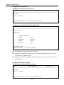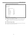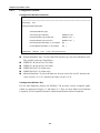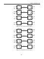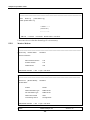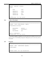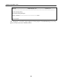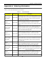
1
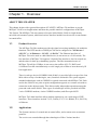
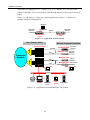
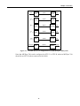
TAINET
MUXpro 700
Fiber Modem
User's Manual
The Professional Partner
TAINET COMMUNICATION SYSTEM CORP.
V1.1
Headquarters:
Beijing Branch:
No. 25, Alley 15, Lane 120,
Sec. 1. Nei-Hu Rd,
Taipei 114, Taiwan
TEL: 886-2-26583000
FAX: 886-2-26583232
3F, A Building, 113 Zhi Chun Lu,
HaiDian District, Beijing, China
Zip Code: 100086
TEL: 86-10-62522081~87
FAX: 86- 10-62522077
07008-00080
2005/11/10
MUXpro 700 User’s Manual
Copyright © 2005 TAINET COMMUNICATION SYSTEM CORP.
All right reserved
Printed in Taiwan R.O.C.
Notice
This document is protected by the international copyright law. No part of this publication may
be reproduced by any means without the permission of Tainet Communication System
Corporation.
TAINET is a registered trademark, and Scorpio 1000 as well as MUXpro 700 are trademark of
Tainet Communication System Corporation.
Other product names mentioned in this manual are used for identification purposes only and
may be trademarks or trademarks of their respective companies.
The information provided from Tainet Communication System Corporation is believed to be
accurate. Any changes and enhancements to the product and to the information thereof will
be documented and issued as a new release to this manual.
Trademark
All products and services mentioned herein are the trademarks, service marks, registered
trademarks or registered service marks of their respective owners.
-i-
MUXpro 700 User’s Manual
ABOUT THIS MANUAL
This section guides you on how to use the manual effectively. The manual contains information
needed to install, configure, and operate TAINET’s MUXpro 700 termination units. The summary of
this manual is as follows:
Chapter 1:
Overview
Describes SCORPIO 1000 and how to use MUXpro 700 in several
applications.
Chapter 2:
Specifications
Describes the features, specifications and applications of MUXpro
700.
Chapter 3:
Interfacing
Introduces all the interfaces, including front panel and rear panel.
Chapter 4:
Installation
Step-by-step guide to assist user to install and verify the MUXpro
700.
Chapter 5:
Operation Of Cid
Gives a description of the CID (Craft Interface Device).
Appendix A: Order Information
Describes all the MUXpro 700 series products.
Appendix B: Menu Tree
Describes the LCD and VT-100 menu tree.
Appendix C: Pin Assignment
Describes all cables and connectors with pin definition.
Appendix D: Trouble Shooting
Provides brief trouble shooting list.
Appendix E: Trouble Report
Trouble Report Form
Appendix F: Glossary
-ii-
MUXpro 700 User’s Manual
SYMBOLS USED IN THIS MANUAL
3 types of symbols are used throughout this manual. These symbols are used to advise the users
when a special condition arises, such as a safety or operational hazard, or to present extra
information to the users. These symbols are explained below:
Warning:
This symbol and associated text are used when death or injury to
the user may result if operating instructions are not followed
properly.
Caution:
This symbol and associated text are used when damages to the
equipment or impact to the operation may result if operating
instructions are not followed properly.
Note:
This symbol and associated text are used to provide the users with
extra information that may be helpful when following the main
instructions in this manual.
-iii-
MUXpro 700 User’s Manual
WARRANTY AND SERVICE
If there are any questions, contact your local sales
representative, service representative, or
distributor directly for any help needed. You might
use one of the following methods..
Contact:
Via the Internet: visit our World Wide Web site at http://www.tainet.net
Via the Sales Representatives:
HQ
No. 25, Alley 15, Lane 120, Sec. 1. N e i -H u Rd. Taipei, Taiwan, R.O.C.
TEL:
(886) 2-2658-3000
E-mail: [email protected]
FAX:
(886) 2-2658-3232
URL:
http://www.tainet.net/
.
-
-
s
-
Beijing Branch
3F, A Building, 113 Zhi Chun Lu, HaiDian District, Beijing, China Zip Code: 100086
TEL: (86) 10-62522081~87
E-mail: [email protected]
FAX: (86) 10-62522077
URL:
http://www.tainet.com.cn
-iv-
MUXpro 700 User’s Manual
TABLE OF CONTENTS
CHAPTER 1. OVERVIEW ...........................................................................................................1
1.1
PRODUCT OVERVIEW ...............................................................................................1
1.2
APPLICATIONS .........................................................................................................1
CHAPTER 2. SPECIFICATION ..................................................................................................5
2.1
MAIN FEATURES.......................................................................................................5
2.2
OPTICAL INTERFACE .................................................................................................5
2.3
NETWORK SIDE INTERFACE .......................................................................................6
2.3.1
T1 Interface ............................................................................................................... 6
2.3.2
E1 Interface ............................................................................................................... 6
2.3.3
V.35 Interface ............................................................................................................ 6
2.3.4
Ethernet Interface...................................................................................................... 6
2.4
USER INTERFACE .....................................................................................................7
2.4.1
2.5
2.6
Connectors ................................................................................................................ 7
TIMING AND SYNCHRONIZATION .................................................................................7
OAM&P .................................................................................................................7
2.6.1
Interface & Self Test .................................................................................................. 7
2.6.2
Maintenance.............................................................................................................. 8
2.6.3
Alarm ......................................................................................................................... 8
2.6.4
Performance.............................................................................................................. 8
2.7
2.8
OTHER TECHNICAL SPECIFICATIONS ..........................................................................8
APPLICATIONS .........................................................................................................9
2.8.1
Cellular Network ........................................................................................................ 9
2.8.2
Campus Network ....................................................................................................... 9
2.8.3
E1 Network .............................................................................................................. 10
CHAPTER 3. INTERFACING ................................................................................................... 11
3.1
FRONT PANEL ........................................................................................................ 11
3.1.1
Status Indicators .......................................................................................................11
3.1.2
Ethernet RJ-45 Pin Assignment................................................................................11
3.2
REAR PANEL ..........................................................................................................12
3.2.1
E1 and T1 RJ-48 Pin Definition for Interface ........................................................... 13
CHAPTER 4. INSTALLATION..................................................................................................15
4.1
UNPACKING ...........................................................................................................15
CHAPTER 5. OPERATION OF CID .........................................................................................17
5.1
OVERVIEW.............................................................................................................17
5.2
CONFIGURATION ....................................................................................................18
5.2.1
Configuration–System ............................................................................................. 19
-v-
MUXpro 700 User’s Manual
5.2.2
Configuration–Interface ........................................................................................... 21
5.2.3
Configuration–Modem ............................................................................................. 26
5.2.4
Configuration-Security ............................................................................................. 28
5.3
MONITOR ..............................................................................................................29
5.3.1
Monitor-Alarm .......................................................................................................... 29
5.3.2
Monitor-Modem ....................................................................................................... 32
5.4
SOFTWARE DOWNLOAD ..........................................................................................33
5.5
DIAGNOSIS ............................................................................................................33
APPENDIX A
ORDERING INFORMATION .......................................................................35
APPENDIX B
MENU TREE....................................................................................................37
APPENDIX C
PINS ASSIGNMENT.......................................................................................41
APPENDIX D
TROUBLE SHOOTING .................................................................................47
APPENDIX E
TROUBLE REPORT.......................................................................................49
APPENDIX F
GLOSSARY......................................................................................................51
-vi-
MUXpro 700 User’s Manual
FIGURES
FIGURE 1-1
APPLICATION OF BACK-TO-BACK ................................................................................................ 2
FIGURE 1-3
POSSIBLE INTERFACE CONFIGURATION OF S1000/MUXPRO 700 SYSTEM ................................... 3
FIGURE 2-2
NETWORK APPLICATION OF THE MUXPRO 700 WITH G.703 I/F ................................................. 10
FIGURE 2-3
NETWORK APPLICATION OF THE MUXPRO 700 ......................................................................... 10
FIGURE 3-3
DB-25 FOR E1/T1 AND VARIOUS DTE INTERFACE .................................................................... 13
FIGURE 5-1
STU-C SIDE ACTIVATED LOOPBACK ........................................................................................ 27
FIGURE 5-2
STU-R SIDE ACTIVATED LOOPBACK ........................................................................................ 27
FIGURE C-1
THE CONVERSION CABLE OF DB-25(M) TO V.35(F) ................................................................. 41
FIGURE C-2
DB-25M INTERFACE ................................................................................................................ 41
FIGURE C-3
V.35 INTERFACE ...................................................................................................................... 41
FIGURE C-4
RS-530 INTERFACE ................................................................................................................. 42
FIGURE C-5
DB-37F INTERFACE................................................................................................................. 43
FIGURE C-6
X.21 INTERFACE ...................................................................................................................... 44
FIGURE C-7
DB-9 INTERFACE ..................................................................................................................... 45
FIGURE C-8
RJ-45 INTERFACE ................................................................................................................... 45
-vii-
MUXpro 700 User’s Manual
TABLES
TABLE 2-1
TIMING AND SYNCHRONIZATION ...................................................................................................... 7
TABLE 3-1
INDICATORS ON FRONT PANEL ...................................................................................................... 12
TABLE 3-2
4E1/4T1 INTERFACE PIN ASSIGNMENT .......................................................................................... 13
TABLE 3-3
RJ-48 E1/T1 PIN DEFINITION ........................................................................................................ 13
TABLE 5-1
FIBER ALARMS DESCRIPTION ..................................................................................................... 30
TABLE 5-2
T1/E1 ALARMS DESCRIPTION ....................................................................................................... 30
TABLE A-1
ORDER INFORMATION ................................................................................................................... 35
TABLE B-1
VT-100 MENU TREE .................................................................................................................... 37
TABLE C-1
V.35 CABLE PIN DEFINITION ......................................................................................................... 42
TABLE C-2
RS-530 CONNECTOR PIN DEFINITION ........................................................................................... 42
TABLE C-3
V.36/RS-449 CABLE PIN DEFINITION ........................................................................................... 43
TABLE C-4
X.21 CABLE PIN DEFINITION ........................................................................................................ 44
TABLE C-5
DB-9 CONNECTOR PIN DEFINITION ............................................................................................... 45
TABLE C-6
LAN RJ-45 CONNECTOR PIN DEFINITION ..................................................................................... 45
-viii-
Chapter 1 Overview
Chapter 1. Overview
ABOUT THIS CHAPTER
This chapter begins with a general description of TAINET’s MUXpro 700 and how to use the
MUXpro 700 in several applications and show the possible interface configurations of MUXpro
700 System. The MUXpro 700 can connect to Scorpio 1000(S1000), S1000 is a high-density
universal rack mounted system, which had various interface modules can be used as a concentrator
in central office.
1.1
Product Overview
The MUXpro 700 fiber modem provides the signal converting /multiplex /de-multiplex
functions. The DTE interface of MUXpro 700 can be configured as “4*Ethernet +
4*E1/T1” or “4*Ethernet + 3*E1/T1 + 1*DATA”. The Ethernet interfaces of
MUXpro 700 can be used as a hub liked device (it can not act as a LAN switch). The
line interface of MUXpro 700 supports 2 Optical Fiber interfaces. One for normal use,
and the other for back up (redundancy) purpose. The fiber transmission rate of
MUXpro 700 will be 125Mbps, it can convey the traffics of E1/T1, DATA and
10/100baseTx traffic simultaneously over the single pair of fiber to meet the newly IP
base application.
There is rack type device SCORPIO 1000 (S1000), it provides full coverage of the Last
Mile with a variety of technologies, rates, interfaces and media. The system supports
standard technologies such as G.SHDSL or optical connected with MUXpro 700. Each
card in the S1000 is in a point-to-point configuration opposite to a remote unit with no
connection to the adjacent cards. This allows totally independent operation among the
ports and cards on the S1000. Three types of technologies will be provided in S1000:
2-wire G.SHDSL modems, 4-wire G.SHDSL modems, and fiber optic MUX.
MUXpro 700’s data interfaces allow modem connectivity via a wide range of DTE
interfaces. These interfaces include T1, E1, DATA (V.35, V.36 / RS449, X.21, RS-530),
or Ethernet.
1.2
Applications
The System consists of a central unit at central office, and a remote unit, at customer
premises.
The services are extended through the technologies of fiber. Various interface
-1-
Chapter 1 Overview
extensions are supported: E1, T1, DATA (V.35, V.36 / RS449, X.21, RS-530), and
Ethernet (MUXpro 700 can be acted as a hub through the four LAN ports on the front
panel).
Figure 1-1 and Figure 1-2 show two typical applications. Figure 1-3 depicts the
possible interface configurations.
CID/Telnet
E1/T1/V35/
Ethernet
V.24/Ethernet
E1/T1/V35/
Ethernet
Optical
MUXpro 700
(CPE)
MUXpro 700
(CO)
Figure 1-1 Application of Back-to-back
Telco Central Office
Remote Customer Premises
Scorpio 1000
ADM
G.SHDSL
Scorpio 1400
MUXpro 700
Fiber
Transport
Network
E1/T1/V35/
Ethernet
MUXpro 700
ADM
Fiber
MUXpro 700
Fiber
V.24
CID
V.24
Ethernet
Router
UNMS
DataBase
server
CID/
Telnet
TFTP server
Figure 1-2 Application of S1000/MUXpro 700 System
-2-
E1/T1/V35/
Ethernet
4xE1/T1
3E1/T1+DATA
CID
Chapter 1 Overview
DS1
E1
DS1
E1
V.35
Ethernet
Optical
STU-C
Optical
STU-C
Optical
STU-C
Optical
STU-C
Optical
STU-C
Optical
STU-C
STU-R
STU-R
STU-R
STU-R
STU-R
STU-R
DS1
E1
V.35
V.35
V.35
Ethernet
Figure 1-3 Possible Interface Configuration of S1000/MUXpro 700 System
Note that MUXpro 700 can be configured as STU-C or STU-R, whereas MUXpro 700
should be an STU-R when connected with S1000.
-3-
Chapter 2 Specification
Chapter 2. Specification
ABOUT THIS CHAPTER
To let the user understand the TAINET MUXpro 700, this chapter begins with its main features.
Then, the chapter continues to present the FIBER interface, the network side interface, timing and
synchronization, OAM (Operation, Administration and Maintenance) and technical specifications.
The last part of this chapter is devoted to the applications of TAINET MUXpro 700 family in
different networks, which include cellular network, campus network and E1 network.
2.1
Main Features
Listed below are the main features of the MUXpro 700:
MUXpro 700 supports DTE interface: T1, E1, DATA (V.35, X.21, RS-530, V.36 /
RS449), Ethernet.
Support line data rate of 125Mbps.
Transmission distance is up to 40Km.
Support either 4*E1/T1 + Ethernet or 3*E1/T1+DATA+Ethernet connection for
application.
Support Timing and Synchronization: Local (internal) timing , Line timing (loop
received clock), DTE timing.
For test and diagnostic purpose the MUXpro 700 system provides various
loopback activated and deactivated function.
Management by UNMS or CID.
Remote control / monitoring via Telnet and Ethernet.
Two optical line interfaces support 1:1 line backup (redundancy) function.
Remote software upgrade via TFTP.
2.2
Optical Interface
Single Mode.
Connector: FC/PC or SC.
Laser Wavelength: 1310/1550nm for single mode operation.
Fiber Size: 9/125 um.
Transmit Power: -5 dBm (min).
Receive Power: -34 dBm (min) (For BER 10-10).
Dynamic Range: 29 dB (For BER 10-10).
-5-
Chapter 2 Specification
2.3
Network Side Interface
2.3.1
T1 Interface
Bit Rate: 1,544 Kbit / s ± 50 ppm.
Frame Format: SF (D4), ESF, field selectable.
Line Code: AMI or B8ZS, field selectable.
Impedance: Nominal 100 ohms ± 5% resistive.
Jitter performance: Meet ITU-T G.824 requirements.
Physical Connection Type: DB25 (female) or RJ-45 (100 ohms) in Connector
Module.
CRC: CRC-6
2.3.2
E1 Interface
Comply with G.703 Standard.
Bit Rate: 2,048 Kbit / s ± 50 ppm.
Frame Format: meet ITU-T G.704 standard.
Line Code: High Density Bipolar of Order 3 (HDB3).
Impedance: Nominal 120 ohms ± 5% or 75 ohm.
Jitter performance: Meet ITU-T G.823 requirements.
CRC: CRC-4.
Physical Connection Type: DB25 (female) or RJ-45 (120 ohms) in Connector
Module.
2.3.3
V.35 Interface
Software configurable for V.35 or RS530 or RS-449/V.36 or X.21.
Data inversion (Normal Data or Inverse Data mode selected).
Date rate: n x 64K bps (n = 1 to 32).
Connector: DB-25 with adaptive cable.
Clocking mode: DCE slave or DCE external.
Clock inversion.
Control lead:
X.21: C/I.
V.35: DTR/RTS/DSR/DCD/CTS/TM.
V.36: DTR/RTS/DSR/DCD/CTS.
2.3.4
Ethernet Interface
Meet IEEE 802.3 Relative requirements.
Connector: RJ-45.
10/100M Auto-Negotiation.
-6-
Chapter 2 Specification
2.4
User Interface
2.4.1
Connectors
Optical port: FC/PC or SC.
Ethernet port: RJ-45.
E1/T1 port: DB25 (female).
DATA port: DB25 (female)
2.5
Timing and Synchronization
Table 2-1 shows three modes to be field selectable.
Table 2-1
Timing and Synchronization
Mode
STU-C Symbol
STU-R Symbol
Example
Number
Clock Reference
Clock Reference
Application
1
2
Local oscillator
Received symbol
(internal timing)
clock
Transmit data clock Received symbol
(DTE timing)
clock
"Classic" HDSLP
synchronous transport Synchronous
in both directions.
Transmit data clock Received symbol
downstream transport
(DTE timing)
and bit-stuffed
clock
upstream is possible.
2.6
lesiochronous
Main application is
Synchronous
3
Mode
Hybrid:
downstream
Synchronous
upstream:
Plesiochronous
OAM&P
OAM&P (Operation, Administration, Maintenance and Performance) of the MUXpro
700 is listed below:
2.6.1
Interface & Self Test
Transparent UART over 100Base-Fx Ethernet Link for in-band management.
LEDs for local monitor and simple trouble-shooting.
CPU self test
ROM, RAM, interface chipset read/write
Fiber interface loop back test
E1/T1 interface loop back test
DATA interface loop back test
-7-
Chapter 2 Specification
Power monitoring
2.6.2
Maintenance
Power On Self Test.
Watch Dog Timer.
Commanded by CPU.
2.6.3
Alarm
Fiber interface LOS.
T1/E1 interface LOS.
T1/E1 interface AIS.
T1/E1 interface LOF.
T1/E1 interface RAI.
2.6.4
Performance
T1/E1 interface ES.
T1/E1 interface SES.
T1/E1 interface UAS.
2.7
Other Technical Specifications
Table 2-2 gives the other specifications of the MUXpro 700.
Table 2-2
Other Specifications of the MUXpro 700
Size
Dimension
212mm(W) x 286mm(D) x 42mm (H)
Safety
Vibration
Meet FCC part 68 requirements
Safety
Meet EN60950, FCC part 68 requirements
EMI/EMC
Meet CE & FCC part 15 class B requirements
Power Requirement
Input
AC input or DC input voltage: 110V~220VAC or -48VDC
Power Consumption
10 W (TBD)
Environments
Temperature
Operation: 0 ~ 45 ºC
Storage and Transportation: -20 ~ 70 ºC
Operation: 5 ~ 90 % RH (Relative Humidity)
Humidity
Storage and Transportation: 5 ~ 95 % RH
-8-
Chapter 2 Specification
2.8
Applications
The application of TAINET’s MUXpro 700 is very similar with Scorpio 1400 systems,
which include cellular network, campus network and E1/T1 network but the line media.
The optical media can support longer transmitted distance and wider bandwidth
prevented it from interfering. The transmission distance of single mode optical fiber
can be reach to 40Km in according to the standard.
2.8.1
Cellular Network
The cellular network user will need to lease larger numbers of E1 circuits in order to
connect remote cell sites to mobile telephone switching offices (MTSOs). TAINET
MUXpro 700 provides an alternative to standard repeater E1 service. Figure 2-1 shows
a cellular network application.
Figure 2-1 Point to point Interconnection is instead of E1
2.8.2
Campus Network
The MUXpro 700 is well suited to the campus applications. Figure 2-2 and Figure 2-3
show two general campus applications where remote PBX or routers are interconnected
across a campus using two MUXpro 700. One unit is configured as a central office site
(CO) unit and the other is the customer premise equipment (CPE) unit.
-9-
Chapter 2 Specification
Figure 2-2
Network Application of the MUXpro 700 with G.703 I/F
Figure 2-3
Network Application of the MUXpro 700
Each MUXpro 700 is configured at the factory to operate on the CO side of an E1
connection. However, you can easily modify settings intended for the CO into settings
for CPE.
2.8.3
E1 Network
The MUXpro 700 can be deployed to replace traditional E1 network, without the
repeater in the E1 network and effectively the utilization of the existing twisted copper
pair.
-10-
Chapter 3 Interfacing
Chapter 3. Interfacing
ABOUT THIS CHAPTER
In this chapter, we will focus our attention on the interfaces of the MUXpro 700. First, the front
panel of the MUXpro 700 will be discussed. After that, we will examine in more detail the rear
panel of the MUXpro 700.
3.1
Front Panel
The front panel of MUXpro 700, as illustrated in Figure 3-1, contains four main
sections, i.e. the LAN RJ45 connector, optical interfaces, LED indicators and
management RJ45 interface.
From the status indicators of front panel, users can obtain useful information to monitor
the status of the MUXpro 700.
10/100
ACT 10/100
1
ACT
MUXpro 700
3
Management
Optical 1
Tx1
2
Rx1
Optical 2
Tx2
Rx2
Optical
1
2
DATA
E1/T1
1
2
10/100
3
ACT
PWR
4
4
LAN
FRONT PANNEL
Figure 3-1 Front Panel of the MUXpro 700
3.1.1
Status Indicators
The status indicators of the MUXpro 700 are depicted in Table 3-1. There are eight
LEDs, which are Optical 1, Optical 2, DATA, E1/T1 1, E1/T1 2, E1/T1 3, E1/T1 4 and
power. These LEDs display the system status.
3.1.2
Ethernet RJ-45 Pin Assignment
-11-
Chapter 3 Interfacing
Pin
Description
1
TX+
2
TX-
3
RX+
4
NC
5
NC
6
RX-
7
NC
8
NC
Table 3-1
Indicators on Front Panel
LED
Description
Color
Off
Flashing 0,5 sec
Always On
PWR
Power
Green
No Power
N/A
Power OK
DATA
DATA CPE
Failure
N/A
OK
Optical 1, 2
Loop
Handshaking/
Connecting
Training
Idle
E1/T1
Red
Green
Failure
Green
E1/T1 CPE
1,2,3,4
3.2
Green
N/A
Red
N/A
Traffic OK
Failure
Rear Panel
The rear panel of the MUXpro 700. Users may connect the MUXpro 700 to other
devices or equipments via these interfaces.
0V
-48V
I
O
CRAFT
E1/T1
DTE
REAL PANNEL
Figure 3-2
Rear Panel of the MUXpro 700
The following connectors/devices appear on the rear panel of the MUXpro 700.
-12-
Chapter 3 Interfacing
1 Power On / Off: The MUXpro 700’s power switch
2 Power Receptacle: Power plug for a AC power cable
3 DC power connector: Power connector for DC power
4 Ground Terminal: Ground output terminal, connect to earth.
5 Craft Interface: 9 pin female serial D-sub connector
6 E1/T1 Interface: E1/T1 interface.
7 DTE Interface: Data terminal equipment port
The MUXpro 700 supports various DTE (Data Terminal Equipment) interfaces
depending on user requirements. Connector type is a 25 pins female connector for
E1/T1, V.35, X.21, RS-530, and V.36 / RS449. Tainet will provide the cable converter
for various interfaces.
Figure 3-3 DB-25 for E1/T1 and various DTE Interface
The E1 / T1 interface uses a D-sub25 connector. Pin descriptions are shown in the
following table:
Pin number
1
2
3
4
5
6
7
8
9
10
11
12
13
Description
PortD transmit −
PortD receiver +
PortC receiver +
PortC transmit −
PortB transmit −
PortB receiver +
PortA receiver +
PortA transmit −
Table 3-2
3.2.1
Pin number
14
15
16
17
18
19
20
21
22
23
24
25
Description
PortD transmit +
PortD receiver −
PortC receiver −
PortC transmit +
PortB transmit +
PortB receiver −
PortA receiver −
PortA transmit +
4E1/4T1 interface pin assignment
E1 and T1 RJ-48 Pin Definition for Interface
Pin number
1
2
3
4
Description
Receiver Receiver +
Transmit Table 3-3
Pin number
Description
5
Transmit +
6
7
8
RJ-48 E1/T1 pin definition
-13-
Chapter 4 Installation
Chapter 4. Installation
ABOUT THIS CHAPTER
In this chapter, we will present the installation guide for the MUXpro 700. It begins with a checklist
for unpacking the shipping package.
4.1
Unpacking
The MUXpro 700’s shipping package includes the following items:
1 MUXpro 700 standalone unit
1 User’s manual
1 Power cable
1 DB-25 to 4E1 cable converter
Optional items(users specify the type of DATA port)
DB25 to ITU-T V.35 / RS530 / X.21 DATA interface
V.35 cable
X.21 cable
RS-530 cable
V.36 cable
-15-
Chapter 5 Operation of CID
Chapter 5. Operation of CID
ABOUT THIS CHAPTER
In this chapter, you will be introduced to the CID (Craft Interface Device) VT-100 operation of
MUXpro 700. The chapter starts with an overview of MUXpro 700’s CID. In addition, each main
menu item of the MUXpro 700’s CID, such as Configuration, Monitor, Software Download and
Diagnosis, will be discussed.
5.1
Overview
The craft port for configuration is set to Speed: 115200, Data bit: 8, Parity: n, Stop bit:
1, Flow control: n. When startup the device, the following messages will appear before
the screen displays the Application software code.
RAM test OK!!SelfTest1 OK!
SelfTest2 OK!
SelfTest3 OK!
Select 'a' in 1 second-->into Diagnostic mode, or to AP:
dwHeaderCheckSum=0xe9369793 11:59:31
code checksum OK = 0x5766979
At startup of the AP, press Enter, the CID will prompt user to enter the password for
access into the system. The default user name and password is tainet.
!!! Welcome to Access TAINET MUXpro 700 !!!
Please Enter User Name :
tainet
Password : ******
The CID offers user-friendly menu-driven user interface. The following figure depicts
the structure of the interface. The top tier command options include Configuration,
Monitor (status), Software Download and Diagnosis (Test).
-17-
Chapter 5 Operation of CID
System
TAINET MUXpro 700
Version 1.00
Tier 2
=============================================================================
Tier 3
[IP]
Trap IP
DateTime
Default
Reset
Product Name
Software Version
IP Configuration
IP Configuration
Tier 4 or
description
IP Address
[192.168.1.1
]
NetMask
[255.255.255.0
]
Default Gateway
[191.168.1.254
]
input
operational hint
Press: '0' - '9', '.', SPACE, BS, DEL
TAB,ENTER: next field
'<':left
'>':right
ESC: abort
Product Name: TAINET MUXpro 700.
Software Version: the software version number.
Tier 2: The second tier of the current screen.
Tier 3: The next tier of the current screen.
Tier 4 or description: The fourth tier of the current screen and / or its description.
Input: the values to be set by the user.
Operational hint: a hint for the user during operation.
5.2
Configuration
After the password checks out, the CID will bring up the top page or the configuration
main menu. There are four items on this page, System, Interface, Modem, and
Security.
MAIN
TAINET MUXpro 700
Version 1.03
=========================================================================
[Configuration]
System
Monitor
Interface
Software Download
Modem
ENTER:select TAB:next '<':left
Diagnosis
Security
'>':right ESC:previous menu
-18-
Chapter 5 Operation of CID
5.2.1
Configuration–System
Configuration
TAINET MUXpro 700
Version 1.03
========================================================================
[System]
Interface
Modem
CO/CPE Mode IP
Security
Trap IP DateTime
ENTER:select TAB:next '<':left
Default
'>':right ESC:previous menu
Before you can remote control / monitoring the device. Setting IP address is required
for managing the system via the Management Ethernet port in the Front Panel. This is a
must for Telnet and TFTP management.
Configuration-System-CO/CPE Mode
System
TAINET MUXpro 700
Version 1.03
=======================================================================
[CO/CPE Mode]
IP
Trap Ip
DateTime
Default
Set CO/CPE Mode
Configure Muxpro 700 CO/CPE Mode
Mode
[CO]
Press: SPACE to select
TAB,ENTER:next field '<':left
'>':right ESC:abort
The CO device generates the source clock. In opposite device, should be set to CPE
mode to follow the CO clock.
Configuration-System-IP
System
TAINET MUXpro 700
Version 1.03
========================================================================
CO/CPE Mode
[IP]
Trap Ip
DateTime
Default
IP Configuration
IP Configuration
IP Address
[192.168.1.1 ]
NetMask
[255.255.255.0]
Default Gateway
[191.168.1.254]
Press: '0' - '9', '.', SPACE, BS, DEL
TAB,ENTER:next field '<':left
'>':right ESC:abort
Above step sets the local device’s IP address. The IP address has to be in the same
sub-network with your remote computer IP address.
-19-
Chapter 5 Operation of CID
Configuration-System-Trap IP
System
TAINET MUXpro 700
Version 1.03
====================================================================
CO/CPE Mode
IP
[Trap Ip]
DateTime
Default
Trap IP Configuration
TrapIP Configuration
Trap IP0 Address
[210.65.231.120
Trap IP0 Status
[Inactive]
Trap IP1 Address
[0.0.0.0
Trap IP1 Status
[Inactive]
Trap IP2 Address
[0.0.0.0
Trap IP2 Status
[Inactive]
Trap IP3 Address
[0.0.0.0
Trap IP3 Status
[Inactive]
Trap IP4 Address
[0.0.0.0
Trap IP4 Status
[Inactive]
]
]
]
]
]
Press: '0' - '9', '.', SPACE, BS, DEL
TAB,ENTER:next field '<':left '>':right ESC:abort
MUXPro 700 supports four separate points for Network Management System. The
TrapIP is the IP address of remote system.
Configuration-System-Date Time
System
TAINET MUXpro 700
Version 1.03
==============================================================================
CO/CPE Mode
IP
Trap Ip
[DateTime]
Default
Date and Time Setup
Date & Time Setup
Year
[2004 ]
Month
[1 ]
Day
[12 ]
Hour
[16 ]
Minute
[27 ]
Second
[18 ]
Press: '0' - '9', SPACE, BS, DEL
TAB,ENTER:next field '<':left
'>':right ESC:abort
-20-
Chapter 5 Operation of CID
Date-Time: The system provides RTC (Real Time Clock) and supports BCD
coded century, year, month, date, day, hours, minutes, and seconds with automatic
leap year compensation valid up to the year 2100.Set the Date / Time to correctly
time-stamping the alarm or PM data report. The date/time will be stored in
non-volatile memory, so data will not be lost even when powering off the system
(MPU).
Configuration-System-Default
Default: Reset the configuration data of the device to default values.
5.2.2
Configuration–Interface
Configuration
TAINET MUXpro 700
Version 1.03
==============================================================================
System
[Interface]
FIBER
T1
E1
Modem
Security
DATA
ENTER:select TAB:next '<':left
'>':right ESC:previous menu
There are four interface types, which are FIBER, E1, T1 and DATA, available for the
MUXpro 700. In addition, the DATA interface also includes V.35, X.21, V36 / RS499,
and RS530.
Configuration–Interface–FIBER
Interface
[FIBER]
Near End
TAINET MUXpro 700
T1
E1
Version 1.03
DATA
Far End
ENTER:select TAB:next ‘<’:left
‘>’:right ESC:previous menu
There are two sub-items for FIBER parameter, which are Near End and Far End. Near
End is the device you are controlling and the corresponding device is Far End. Users
can set the parameters of Near End and/or Far End device.
-21-
Chapter 5 Operation of CID
Configuration–Interface–FIBER-Near End
FIBER
[Near End]
TAINET MUXpro 700
Version 1.03
Far End
Configure Fiber Near End Parameter
OE OPTION
[Hardware Auto selection]
OE LOOP
[OE1]
DATA PORT LOCATION
EMPTY
Press: SPACE to select
TAB,ENTER:next field '<':left
'>':right ESC:abort
OE OPTION: The configurable values are Hardware Auto selection or Software
configuration. The near end site will connect itself with far end site automatically
when selected Hardware Auto selection. Or, the connection is established by user
defined (OE1 or OE2) when the Software configuration was selected.
OE LOOP: The value of this optical loop selection is OE1 or OE2. OE1 is the
master line interface. OE2 is the backup line for OE1.
DATA PORT LOCATION: EMPTY EMPTY, PORT1, PORT2, PORT3, PORT4
Configuration–Interface–FIBER-Far End
FIBER
TAINET MUXpro 700
Version 1.03
==============================================================================
Near End
[Far End]
Configure Far End Parameter
OE OPTION
[Hardware Auto selection]
OE LOOP
[OE1]
DATA PORT LOCATION
[PORT1]
Press: '0' - '9', SPACE, BS, DEL
TAB,ENTER:next field '<':left
'>':right ESC:abort
OE OPTION: The configurable values are Hardware Auto selection or Software
configuration.
OE LOOP: The value of this optical loop selection is OE1 or OE2. OE1 is the
master line interface. OE2 is the backup line for OE1.
DATA PORT LOCATION: PORT1, PORT2, PORT3, PORT4, EMPTY
A TCA (Threshold Crossing Alert) will be reported if the SNR (Signal to Noise Ratio)
margin is lower, or if the Attenuation is higher than the set value. The TCA will be
-22-
Chapter 5 Operation of CID
time-stamped and logged into local memory and in UNMS database. Users can
configure the values of Far End and/or Near End.
Configuration–Interface–T1
T1
TAINET MUXpro 700
Version 1.03
==============================================================================
[Parameters]
Near End
Far End
ENTER:select TAB:next '<':left
'>':right ESC:previous menu
MUXpro 700 supports one T1 interface to extend the transmission service. Near End is
the device you are controlling and the corresponding device is Far End.
Configuration-Interface-T1-Near End
Parameters
TAINET MUXpro 700
Version 1.03
==============================================================================
[Near End]
Far End
Configure T1 Near End Parameters
Configure T1 Parameters
PortNO
PORT1
Frame Mode
Unframed
LineCoding
[AMI ]
Idle Pattern
[0xff]
Cable Length
[533~655]
Press: SPACE to select
TAB,ENTER:next field '<':left
'>':right ESC:abort
There are four ports on the MUXpro 700 (no data interface selected), in the beginning,
users must specify the associated port from port1 to port4.
Frame Mode: Possible values are Unframed.
LineCoding: AMI or B8ZS
Idle Pattern: Sending pattern on the unused time slots. The possible values are
0x7f and 0xff.
Cable Length: Possible values are 0-133, 133-266, 266-399, 399-533,
533-655.The T1 circuit provides the function of cable length (from 0 to 200
meters) compensation.
-23-
Chapter 5 Operation of CID
Configuration–Interface–E1
Configuration-Interface-E1-Parameter
E1
TAINET MUXpro 700
Version 1.03
==============================================================================
[Parameters]
Near End
Far End
ENTER:select TAB:next '<':left
'>':right ESC:previous menu
Configuration-Interface-E1-Parameter-Near End
Parameters
TAINET MUXpro 700
Version 1.03
==============================================================================
[Near End]
Far End
Near End of E1
Configure E1 Parameters
PORTNO
PORT1
Frame Mode
Unframed
Impedance
Balance
Idle Pattern
[0xff]
Press: SPACE to select
TAB,ENTER:next field '<':left
'>':right ESC:abort
Frame Mode: Possible values are Unframed.
Impedance: Nominal 120 ohms resistive symmetrical (Balance) pair or 75 ohm
asymmetrical (Unbalance) pair
Idle Pattern: Bit sending pattern in the unused time slots. The possible values are
0x7f and 0xff.
Configuration–Interface–DATA
Configuration-Interface-DATA-Parameters
DATA
TAINET MUXpro 700
Version 1.03
==============================================================================
[Parameters]
Near End
Far End
ENTER:select TAB:next '<':left
'>':right ESC:previous menu
-24-
Chapter 5 Operation of CID
Configuration-Interface-DATA-Parameters-Near End
Parameters
TAINET MUXpro 700
Version 1.03
==============================================================================
[Near End]
Far End
Near End of DATA
Configure DATA Parameters
PORTNO
PORT1
DTEType
[V35
Tx data inversion
[normal ]
Rx sample edge
[Rising ]
Rx data inversion
[normal ]
E1 Header CRC
[disable]
exc-pin detect
[Enable ]
Timing Source
[DTE]
]
Press: SPACE to select
TAB,ENTER:next field '<':left
'>':right ESC:abort
DTEType : V35, V36 / RS449, X21, or RS530
Tx/Rx data inversion: normal or inverse. The V.35 interface of STU-R provides
data inversion capability used to protect against the occurrence of low pulse
density.
Rx sample edge: Rising or Falling.
E1 Header CRC: disable or enable.
Exc-pin detect: enable or disable the external clock pin detection of V.35 interface.
Timing Source: Internal, Dte, External or Line.
-25-
Chapter 5 Operation of CID
5.2.3
Configuration–Modem
Configuration-Modem-Parameter
Modem
TAINET MUXpro 700
Version 1.03
==============================================================================
[Parameters]
Test
Configure Modem Parameters
Set Required Modem Type
Actual Card Type of Modem
FIBER-E1T1-4P
Required Modem Type of Near End
[FIBER-E1-4P ]
Required Modem Type of Far End
[FIBER-E1-4P
Near End Modem Data Rate: (1~32) *64kbps
[32
]
Far End Modem Data Rate: (1~32) *64kbps
[32
]
ENTER:select TAB:next '<':left
]
'>':right ESC:previous menu
Required Modem Type: To select the DTE interface type for near-end and far-end.
The possible values are listed below:
FIBER-E1-4P (Near End * Far End)
FIBER-T1-4P (Near End * Far End)
FIBER-DATA-E1 (Far End only)
FIBER-DATA-T1 (Far End only)
Modem Data Rate: To select the data rate for near-end or far-end. E1 interface the
value is from 1 to 32. T1 interface the value is from 1 to 25.
Configuration-Modem-Test
For test and diagnostic purpose the MUXpro 700 provides various Loopback paths,
which are depicted in Figure 5-1 and Figure 5-2. They are Near End (Local Payload)
Loopback, Local Loopback, Remote Loopback and Remote Payload Loopback.
-26-
Chapter 5 Operation of CID
STU-C
(a)
STU-R
(c)
(b)
(d)
OPTICAL
DS1 or E1
DS1 or E1
STU-C
(a)
STU-R
(c)
(b)
(d)
OPTICAL
V.35
DS1 or E1
STU-C
(a)
STU-R
(c)
(b)
(d)
OPTICAL
V.35
V.35
STU-C
(a)
STU-R
(c)
(b)
(d)
OPTICAL
Ethernet
Ethernet
Figure 5-1 STU-C Side Activated Loopback
STU-C
(d)
STU-R
(c)
(b)
(a)
OPTICAL
DS1 or E1
DS1 or E1
STU-C
(d)
STU-R
(c)
(b)
(a)
OPTICAL
V.35
DS1 or E1
STU-C
(d)
STU-R
(c)
(b)
(a)
OPTICAL
V.35
V.35
STU-C
(d)
STU-R
(c)
(b)
(a)
OPTICAL
Ethernet
Ethernet
Figure 5-2 STU-R Side Activated Loopback
-27-
Chapter 5 Operation of CID
Test
TAINET MUXpro 700
Version 1.03
==============================================================================
[Loopback]
Loopback test
PortNO
PORT1
Loopback Test
[Local PayLoad Loopback ]
Press: SPACE to select
TAB,ENTER:next field '<':left
'>':right ESC:abort
Loopback Test: Possible values are
Normal
Local Loopback
Remote Loopback
Local PayLoad Loopback
Remote PayLoad Loopback
Be Remote Loopback (FarEnd command, Read Only!)
Be Remote PayLoad Loopback (FarEnd command, Read Only
5.2.4
Configuration-Security
Configuration
TAINET MUXpro 700
Version 1.03
==============================================================================
System
Interface
Modem
[Security]
Security Configuration
Login Username
[tainet
]
Login Password
[tainet
]
Press: ASCII, SPACE, BS, DEL
TAB,ENTER:next field '<':left
'>':right ESC:abort
For security, users can define the password for console or telnet login.
-28-
Chapter 5 Operation of CID
5.3
Monitor
Monitor
TAINET MUXpro 700
Version 1.03
==============================================================================
[Alarm]
Alarm
Modem
Alarm Log
Clear alarm Log
SPACE:refresh page '<':page up '>':page down ESC:abort
5.3.1
Monitor-Alarm
Alarm
TAINET MUXpro 700
Version 1.03
==============================================================================
[Alarm]
Alarm Log
Clear Alarm Log
View Real Time Alarm
View Real Time Alarm
Select by
[All
]
SPACE:refresh page '<':page up '>':page down ESC:abort
Select by: Possible values are All, Port1, Port2, Port3, Port4, FIBER OE1 and
FIBER OE2 to list the alarm log.
Alarm
TAINET MUXpro 700
Version 1.03
==============================================================================
[Alarm]
Alarm Log
Clear Alarm Log
View Real Time Alarm
TYPE
Class
1
DSX1(4)_UAS_EXCD_QTR_TRHD
WARNING
2
DSX1(4)_UAS_EXCD_DAY_TRHD
WARNING
3
DSX1(4)_LOS
MAJOR
SPACE:refresh page '<':page up '>':page down ESC:abort
Alarm severity class: Major, Minor, Warning or Clear. The “(4)” means port
number 4.
All TCA (Threshold Crossing Alert) are classified as WARNING. Table 5-1 and Table
5-2 show all FIBER alarms and T1/E1 alarms, respectively.
-29-
Chapter 5 Operation of CID
Table 5-1
Alarm Type
FIBER Alarms Description
Severity Class
FIBER_LOSW
MAJOR
Description
Failure of LOSW
FIBER_LOSWS_QTR_TRHD
WARNING
15-minute LOSW TCA
FIBER_LOSWS_DAY_TRHD
WARNING
1-day LOSW TCA
FIBER_ES_QTR_TRHD
WARNING
15-minute ES TCA
FIBER_ES_DAY_TRHD
WARNING
1-day ES TCA
FIBER_SES_QTR_TRHD
WARNING
15-minute SES TCA
FIBER_SES_DAY_TRHD
WARNING
1-day SES TCA
FIBER_UAS_QTR_TRHD
WARNING
15-minute UAS TCA
FIBER_UAS_DAY_TRHD
WARNING
1-day UAS TCA
FIBER_LOSWS_FE_QTR_TRHD
WARNING
15-minute FE LOSW TCA
FIBER_LOSWS_FE_DAY_TRHD
WARNING
1-day FE LOSW TCA
FIBER_ES_FE_QTR_TRHD
WARNING
15-minute FE ES TCA
FIBER_ES_FE_DAY_TRHD
WARNING
1-day FE ES TCA
FIBER_SES_FE_QTR_TRHD
WARNING
15-minute FE SES TCA
FIBER_SES_FE_DAY_TRHD
WARNING
1-day FE SES TCA
FIBER_UAS_FE_QTR_TRHD
WARNING
15-minute FE UAS TCA
FIBER_UAS_FE_DAY_TRHD
WARNING
1-day FE UAS TCA
FIBER_ATN_TRHD
WARNING
Attenuation TCA
FIBER_FE_ATN_TRHD
WARNING
FE Attenuation TCA
FIBER_SNM_TRHD
WARNING
SNR Margin TCA
FIBER_FE_SNM_TRHD
WARNING
FE SNR Margin TCA
Table 5-2
Alarm Type
T1/E1 Alarms Description
Severity Class
Description
DSX1_LOS
MAJOR
Failure of LOS
DSX1_LOF
MAJOR
Failure of LOF
DSX1_AIS
MAJOR
Failure of AIS
DSX1_RAI
MINOR
Failure of RAI
DSX1_LOS_FE
MAJOR
Failure of FE LOS
DSX1_LOF_FE
MAJOR
Failure of FE LOF
DSX1_AIS_FE
MAJOR
Failure of FE AIS
DSX1_RAI_FE
MINOR
Failure of FE RAI
DSX1_ES_QTR_TRHD
WARNING
15-minute ES TCA
DSX1_ES_DAY_TRHD
WARNING
1-day ES TCA
DSX1_SES_QTR_TRHD
WARNING
15-minute SES TCA
-30-
Chapter 5 Operation of CID
DSX1_SES_DAY_TRHD
WARNING
1-day SES TCA
DSX1_UAS_QTR_TRHD
WARNING
15-minute UAS TCA
DSX1_UAS_DAY_TRHD
WARNING
1-day UAS TCA
DSX1_ES_FE_QTR_TRHD
WARNING
15-minute FE ES TCA
DSX1_ES_FE_DAY_TRHD
WARNING
1-day FE ES TCA
DSX1_SES_FE_QTR_TRHD
WARNING
15-minute FE SES TCA
DSX1_SES_FE_DAY_TRHD
WARNING
1-day FE SES TCA
DSX1_UAS_FE_QTR_TRHD
WARNING
15-minute FE UAS TCA
DSX1_UAS_FE_DAY_TRHD
WARNING
1-day FE UAS TCA
Alarm
TAINET MUXpro 700
Version 1.03
==============================================================================
Alarm
[Alarm Log]
Clear Alarm Log
View Alarm Log
TYPE
Class
Status
Date
Time
1
DSX1(4)_UAS_QTR_TRHD
WARNING
RAISED
01/12/2003
16:46:00
2
FIBER(1)_UAS_QTR_TRHD
WARNING
RAISED
01/12/2003
16:46:00
3
FIBER(2)_LOSWS_QTR_TRHD
WARNING
RAISED
01/12/2003
16:46:00
4
DSX1(3)_UAS_QTR_TRHD
WARNING
CLR
01/12/2003
16:45:00
5
FIBER(1)_UAS_QTR_TRHD
WARNING
CLR
01/12/2003
16:45:00
6
FIBER(2)_LOSWS_QTR_TRHD
WARNING
CLR
01/12/2003
16:45:00
7
DSX1(2)_UAS_QTR_TRHD
WARNING
RAISED
01/12/2003
16:31:00
8
FIBER(2)_UAS_QTR_TRHD
WARNING
RAISED
01/12/2003
16:31:00
9
FIBER(1)_LOSWS_QTR_TRHD
WARNING
RAISED
01/12/2003
16:31:00
10 DSX1(2)_UAS_QTR_TRHD
WARNING
CLR
01/12/2003
16:30:00
11 FIBER(2)_UAS_QTR_TRHD
WARNING
CLR
01/12/2003
16:30:00
12 FIBER(1)_LOSWS_QTR_TRHD
WARNING
CLR
01/12/2003
16:30:00
SPACE:refresh page '<':page up '>':page down ESC:abort
Up to 200 alarm records can be stored without the use UNMS. Many more can be
logged in Database if UNMS is used.
-31-
Chapter 5 Operation of CID
Alarm
TAINET MUXpro 700
Version 1.03
==============================================================================
Alarm
Alarm Log
[Clear Alarm Log]
Clear System Alarm Log
+-Clear ?------+
|<YES> NO
|
+----------------+
TAB:next '>':forward '<':backward ENTER:select ESC:abort
Users can view or clear the alarm logs if it is necessary.
5.3.2
Monitor-Modem
Modem
TAINET MUXpro 700
Version 1.03
===============================================================================
[Version Info]
Modem Status
Led Status
Version Information
Main Hardware Version
1.00
Software Version
1.03
FPGA Version
0.00
TAB,ENTER:next field '<':left
'>':right ESC:abort
Modem
TAINET MUXpro 700
Version 1.03
==============================================================================
Version Info
[Modem Status]
Led Status
Modem Status
PortNO
PORT1
Near End Modem Type
FIBER-E1-4P
Far End Modem Type
FIBER-E1-4P
Near End Port Rate
2048
Trunk Timing Source
Through Mode
TAB,ENTER:next field '<':left
Modem
'>':right ESC:abort
TAINET MUXpro 700
-32-
Version 1.03
Chapter 5 Operation of CID
==============================================================================
Version Info
Modem Status
[Led Status]
Led Status
PortNO
PORT1
LED Status: OE1
Inactive
LED Status: OE2
Inactive
LED Status: E1T1
RED
LED Status: DATA
Inactive
……………..
TAB,ENTER:next field '<':left
5.4
'>':right ESC:abort
Software Download
MAIN
TAINET MUXpro 700
Version 1.03
==============================================================================
Configuration
Monitor
[Software Download]
Diagnosis
Download Software From TFTP Server
Server IP Address
[192.168.1.1
]
File Name
[mp700v103.img ]
Start Downloading
[Yes ]
Press: '0' - '9', '.', SPACE, BS, DEL
TAB,ENTER:next field '<':left
'>':right ESC:abort
TFTP software upgrade is supported. Users can specify the IP address of TFTP server
and file name for downloading through the Management port in the front panel by
cross cable.
5.5
Diagnosis
MAIN
TAINET MUXpro 700
Version 1.03
================================================================================
Configuration
Monitor
Software Download
[Diagnosis]
Trouble Shooting Menu
ENTER:select TAB:next '<':left
'>':right ESC:previous menu
-33-
Chapter 5 Operation of CID
Diagnosis
TAINET MUXpro 700
Version 1.03
==============================================================================
[Trouble Shooting Menu]
View System Debug Messages
debug: 11d0000**************************************************ESS ...
Type 'Q' to Quit
The “Diagnosis” is used by expert engineer for the purpose of troubleshooting. Users may
ignore it if users are not so familiar with it.
-34-
Appendix A Ordering Information
Appendix A Ordering Information
Table A-1 is the order information for your reference.
Table A-1
Part Number
Order Information
Ordering No.
Description
Standalone fiber optic modem w/ 3 E1 balanced interface, one DATA
MUXpro 700AC3E1/DATA/B/?
000-101-0063
(V.35/V.36/RS-530/X.21), and 4-ports 10/100M Ethernet interface,
1310nm for up to 40km distance, FC/PC connector, with built-in
100~240VAC auto range power
Standalone fiber optic modem w/ 4 E1 balanced interface and
MUXpro
700AC-4E1/B/?
000-101-0064
4-ports 10/100M Ethernet interface, 1310nm for up to 40km
distance, FC/PC connector, with built-in 100~240VAC auto range
power
Standalone fiber optic modem w/ 3 E1 unbalanced interface, one
MUXpro 700AC3E1/DATA/U/?
DATA (V.35/V.36/RS-530/X.21), and 4-ports 10/100M Ethernet
000-101-0065
interface, 1310nm for up to 40km distance, FC/PC connector, with
built-in 100~240VAC auto range power
Standalone fiber optic modem w/ 4 E1 unbalanced interface and
MUXpro
700AC-4E1/U/?
000-101-0066
4-ports 10/100M Ethernet interface, 1310nm for up to 40km
distance, FC/PC connector, with built-in 100~240VAC auto range
power
Standalone fiber optic modem w/ 3 E1 balanced interface, one DATA
MUXpro 700DC3E1/DATA/B
000-101-0067
(V.35/V.36/RS-530/X.21), and 4-ports 10/100M Ethernet interface,
1310nm for up to 40km distance, FC/PC connector, with built-in
36~72VDC power
MUXpro
700DC-4E1/B
Standalone fiber optic modem w/ 4 E1 balanced interface and
000-101-0068
4-ports 10/100M Ethernet interface, 1310nm for up to 40km
distance, FC/PC connector, with built-in 36~72VDC power
Standalone fiber optic modem w/ 3 E1 unbalanced interface, one
MUXpro 700DC3E1/DATA/U
000-101-0069
DATA (V.35/V.36/RS-530/X.21), and 4-ports 10/100M Ethernet
interface, 1310nm for up to 40km distance, FC/PC connector, with
built-in 36~72VDC power
MUXpro
700DC-4E1/U
/?
Standalone fiber optic modem w/ 4 E1 unbalanced interface and
000-101-0070
4-ports 10/100M Ethernet interface, 1310nm for up to 40km
distance, FC/PC connector, with built-in 36~72VDC power
Specify power cord
-35-
Appendix A Ordering Information
/A
330-010-0001
North American power cord, 3-pin, 10A/125V, 6 feet
/E
330-010-0002
European power cord, 3-pin (round pin), 10A/250V, 1.83M
/B
330-010-0003
British power cord, 3-pin, 10A/250V, 13A fuse
/I
330-010-0006
India power cord, 3-pin, 6A/250V, 1.83M
/C
330-010-0007
China power cord, 3-pin, 10A/250V, 1.83M
-36-
Appendix B Menu Tree
Appendix B Menu Tree
The VT-100 menu tree for CID port used is shown in Table B-1. The default value of each
parameter is also listed for users’ reference.
Table B-1 VT-100 Menu Tree
Tier 1
Tier 3
/ Tier 2
Configuration/Syste IP
m
Trap Ip
Date Time
Tier 4
Tier 5
Tier 6
Default
Tier 7
Value
(IP Address)
192.168.1.1
(net Mask)
255.255.255.0
(defult GW)
192.168.1.254
TrapIpaddress
0.0.0.0
TrapIpStatus
Inactive
(Date Time)
4160/20/40
40:80:80
Default
Configuration/Interf FIBER
ace
X
Near End
Far End
T1
parameter
(OE Option)
Hardware Auto
Selection
(OE Loop)
OE1
(DATA Port
Location)
Empty
(OE Option)
Hardware Auto
Selection
(OE Loop)
OE1
(DATA Port
Location)
Port1
Near End (Port (Frame Mode)
1,2,3,4)
Unframed
(Line Coding)
AMI,B8ZS
(Idle Patten)
0xff
(Cable Length)
Short haul
(Frame Mode)
Unframed
(Line Coding)
AMI, B8ZS
(Idle Patten)
0xff
(Cable Length)
Short haul
Near End (Port (Frame Mode)
1,2,3,4)
Unframed
Far End(Port
1,2,3,4)
E1
parameter
(Idle Pattern)
<0xff,0x7f>
0xff
(Impedance)
< Unbalance
Unbalance
Balance >
Far End(port
1,2,3,4)
(Frame Mode)
(Idle Pattern)
-37-
Unframed
<0xff,0x7f >
0xff
Appendix B Menu Tree
Tier 1
/ Tier 2
Tier 3
Tier 4
Tier 5
Tier 6
(Impedance)
Default
Tier 7
< Unbalance
Value
Unbalance
Balance >
DATA
Parameters
Near End(port
1,2,,3,4)
Far End(Port
1,2,3,4)
(DTE Type)
V35 V36/RS449 RS530
X21
(Tx data
inversion)
Normal Inverter
(Rx sample
edge)
Rising Falling
(Rx data
inversion)
Normal Inverter
(E1 Header
CRC)
Disable,enable
(exc-pin detect)
Enable, Disable
(Timing
Source)
Internal
(DTE Type)
V35 V36/RS449 RS530
X21
(Tx data
inversion)
Normal Inverter
(Rx sample
edge)
Rising Falling
(Rx data
inversion)
Normal Inverter
(E1 Header
CRC)
Disable,enable
(exc-pin detect)
Enable, Disable
(Timing
Source)
Internal
Configuration/Mode Parameter(port (Required
m
1,2,3,4)
Modem Type of
Near End)
Empty
(Required
Modem Type of
Far End)
Empty
(Far End
Modem Data
Rate:
Input(1~32 )*64
Kbps )
31
Test
Loopback
Loopback
Test(Port
1,2,3,4)
Normal
Local Loopback
Local PayLoad
Loopback
Remote Loopback
Remote PayLoad
Loopback
Be Remote Loopback
Be Remote PayLoad
Loopback
Configuration/Secur Login
ity
Username
tainet
Login
Password
tainet
Monitor
/Alarm
Alarm
View Real Time
Alarm
All
-38-
Appendix B Menu Tree
Tier 1
/ Tier 2
Tier 3
Tier 4
Tier 5
Tier 6
Default
Tier 7
Value
AlarmLog
Clean Alarm
Log
Monitor
/Modem
Version Info
modem
Status(port1,2,
3,4)
X
(main Hw
Version)
1.00
(Sw Version)
1.03
(fpga Version)
0.00
(Near End
modem Type)
(Far End
Modem Type)
(Near End Port
Rate)
(Trunk Timing
Source)
Led Status(port (OE1)
1,2,3,4)
(OE2)
(E1T1)
(DATA)
Software Download
/(Sever IP address)
0.0.0.0
Software Download
/(File name)
Software Download
/(Start downloading)
No
Diagnosis/Trouble
Shooting Menu
-39-
Appendix C Pins Assignment
Appendix C
Pins Assignment
The pin assignment for different interface of MUXpro 700 is depicted in the following sections.
A Conversion Cable is enclosed for converting DB-25 to V.35, V.36, or X.21 interface, as shown in
Figure C-1.
There are three types of Conversion Cables, depending on the customer’s order; the cable is
enclosed in the shipping package.
V.35(F)
DB-25(M)
20cm
Figure C-1
The Conversion Cable of DB-25(M) to V.35(F)
V.35 Interface
Figure C-2 and Figure C-3 respectively illustrate the DB-25M and V.35 interfaces. Refer to Table
C-1 to see the pin definition of V.35 cable.
Figure C-2
DB-25M Interface
Figure C-3
V.35 Interface
-41-
Appendix C Pins Assignment
Table C-1 V.35 Cable Pin Definition
DB-25 Male
Signal
V.35 Female
Source
1
Frame Ground
A
Common
7
Signal Ground
B
Common
4
Request to Send
C
DTE
5
Clear to Send
D
DCE
6
Data Set Ready
E
DCE
8
Data Carrier Detect
F
DCE
20
Data Terminal Ready
H
DTE
2
Transmit Data (A)
P
DTE
3
Receive Data (A)
R
DCE
14
Transmit Data (B)
S
DTE
16
Receive Data (B)
T
DCE
24
Terminal Timing (A)
U
DTE
17
Receive Timing (A)
V
DCE
11
Terminal Timing (B)
W
DTE
9
Receive Timing (B)
X
DCE
15
Terminal Timing (A)
Y
DCE
12
Terminal Timing (B)
AA
DCE
RS-530 Interface
Figure C-4 illustrates the RS-530 Interface.
Figure C-4
RS-530 Interface
Refer to Table C-2 to see the pin definition of RS-530 Connector.
Table C-2 RS-530 Connector Pin Definition
DB-25 Male
Signal
Source
1
Frame Ground
2
Transmit Data (A)
DTE
3
Receive Data (A)
DCE
4
Request to Send (A)
DTE
5
Clear to Send (A)
DCE
6
DCE Ready (A)
DCE
7
Signal Ground
Common
8
Receive line Signal Detector (A)
Common
-42-
DCE
Appendix C Pins Assignment
9
Receive Signal Element Timing (B)
DCE
10
Receive line Signal Detector (B)
DCE
11
EXT. Transmit Signal Element Timing (B)
DTE
12
Transmit Signal Element Timing (B)
DCE
13
Clear to Send (B)
DCE
14
Transmit Data (B)
DTE
15
Transmit Signal Element Timing (A)
DCE
16
Receive Data (B)
DCE
17
Receive Signal Element Timing (A)
DCE
19
Request to Send (B)
DTE
20
DTE Ready (A)
DTE
22
DCE Ready (B)
DCE
23
DTE Ready (B)
DTE
24
EXT. Transmit Signal Element Timing (A)
DTE
18
21
V.36/RS-449 Interface
The DB-37F interface is shown in Figure C-5.
Figure C-5
DB-37F Interface
Refer to Table C-3 to see the pin definition of V.36/RS-449 cable.
Table C-3 V.36/RS-449 Cable Pin Definition
DB-25 Male
Signal
V.36/RS-449 Female
Source
1
Shield
1
Common
2
Send Data (A)
4
DTE
15
Send Timing (A)
5
DCE
3
Receive Data (A)
6
DCE
4
Request to Send (A)
7
DTE
17
Receive Timing (A)
8
DCE
5
Clear to Send (A)
9
DCE
6
Data Mode (A)
11
DCE
20
Terminal ready (A)
12
DTE
8
Receive Ready (A)
13
DCE
24
Terminal Timing (A)
17
DTE
7
Signal Ground
19,20,37
Common
14
Send Data (B)
22
DTE
-43-
Appendix C Pins Assignment
12
Send Timing (B)
23
DCE
16
Receive Data (B)
24
DCE
19
Request to Send (B)
25
DTE
9
Receive Timing (B)
26
DCE
13
Clear to Send (B)
27
DCE
22
Data Mode (B)
29
DCE
23
Terminal Ready (B)
30
DTE
10
Receive Ready (B)
31
DCE
11
Terminal Timing (B)
35
DTE
X.21 Interface
Figure C-6 illustrates the X.21 Interface. For the DB-25 interface, refer to Figure C-2.
Figure C-6
X.21 Interface
Refer to Table C-4 to see the pin definition of V.36/RS-449 cable.
Table C-4 X.21 Cable Pin Definition
DB25 Male
Signal
X.21 Female
1
Shield Ground
1
2
Signal Ground
2
4
TXD(a)
3
3
CTRL(a)
4
8
RXD(a)
5
17
Indication
6
24
RXC(a)
7
7
Signal Ground
8
14
TXD(b)
9
19
CTRL(b)
10
16
RXD(b)
11
10
Indication
12
9
RXC(b)
13
11
EXC(b)
14
G
G
DB-9 Interface
The DB-9 connector interface is shown as Figure C-7.
-44-
Appendix C Pins Assignment
Figure C-7
DB-9 Interface
For the pin definition of DB-9 interface, see Table C-5.
Table C-5 DB-9 Connector Pin Definition
DB9 Female
Signal
Source
2
TXD
DCE
3
RXD
DTE
5
Signal Ground
7
CTS
DTE
8
RTS
DCE
RJ-45 Interface
Figure C-8 illustrates the RJ-45 interface.
8
1
Figure C-8
RJ-45 Interface
Refer to Table C-6 to see the pin definition of LAN RJ-45 connector.
Table C-6 LAN RJ-45 Connector Pin Definition
RJ-45
10Base-T Signal
1
TxD Twist Pair +
2
TxD Twist Pair -
3
RxD Twist Pair +
6
RxD Twist Pair -
-45-
Appendix D Trouble shooting
Appendix D Trouble shooting
Trouble Shooting Table
1
Configured parameter values are lost after equipment restart
When user modifies or changes the parameters, the user should save the configurations
in the flash memory by entering the Confirm- “YES” menu, and then reboot the system
by entering the “Configuration-System-Reset” menu.
2
Console / Telnet / Web User Name and Password
When accessing the device through Telnet or the Web, the user will be prompted to
enter the password. User can try the default user name “tainet” and password “tainet” to
log in.
3
Access denied
There are several conditions that will disable user’s access to the device via Console,
Telnet or the Web.
Message
Solution
Incorrect user
The password entered is incorrect. Check the user name
and password again.
-47-
Appendix E Trouble Report
Appendix E Trouble Report
Company
Local Representation
Purchase Order No
Equipment Serial No
Software Version
Please describe:
1. Testing Network Structure
2. Configuration
3. Testing Network Equipment
4. Trouble Description
E-MAIL:
TEL:
FAX:
Signature:
Date:
TAINET COMMUNICATION SYSTEM CORP.
FAX: 886-2-2658-3232
E-MAIL: [email protected]
-49-
/
/
Appendix F Glossary
Appendix F Glossary
KEYWORD
10 Base-T
EXPLAINATION
Part of the original IEEE 802.3 standard, 10 Base-T is the Ethernet specification of
10Mbps base-band that uses two pair of twisted-pair, Category 3,4 or 5 cabling- using
one pair to send data and the other to receive. 10 Base-T has a distant limit of about
100 meters per segment.
Based on the IEEE 802.3u standard, 100BaseT is the Fast Ethernet specification of
100 Base-T
100Mbps base-band that uses UTP wiring. 100BaseT sends link pulse over the
network when no traffic is present.
Address Mask
The address mask for an IP address is used to identify the boundary between the
network portion of the address and host portion.
Asymmetric Digital Subscriber Line: An evolving high-speed transmission technology
originally developed by Bell-core and mow standardized by ANSI as T1.413.
A、
ADSL
Uses existing UTP copper wires from Telephone Company’s central office to
subscriber’s premises.
B、
Involves electronic equipment in the form of ADSL modems at central office
and subscriber’s premises.
C、
Sends digital signal up and down these copper wires and sends more
information one way than the other- hence the term “asymmetric”.
Address Resolution Protocol is a method to find a host’s physical address from its IP
ARP
address. An ARP request is sent to the network, naming the IP address, then machine
with that IP address returns its physical address so it can receive the transmission.
Asynchronous Transfer Mode. International standard for cell relay in which multiple
service types (such as voice, video, or data) are conveyed in fixed-length (53-byte)
ATM
cells. Fixed-length cells allow cell processing to occur in hardware, thereby reducing
transit delays. ATM is designed to take advantage of high-speed transmission media
such as E3, SONET, and T3.
Authentication
Bandwidth
Proof that the information came from the user or location that repeatedly sent it. One
example of authenticating software is through digital signature.
This is the capacity on a link usually measured in bits-per-second (bps).
Bridging provides LAN-to-LAN frame forwarding services between two or more LANs.
Bridging
Frames from one LAN are forwarded across a bridge to a connected LAN. Bridging
works is similar to the way repeaters work except that bridges forward frame based on
their MAC address.
CBR
Constant Bit Rate: An ATM Forum Q-o-S class created for use in ATM network. CBR is
used for communications on precision clocking to guarantee trustworthy delivery.
-51-
Appendix F Glossary
KEYWORD
CHAP
EXPLAINATION
Challenge Handshake Authentication Protocol is an alternative protocol that avoids
sending password over the wire by using a challenge/response technical.
Class A
Part of Internet Protocol hierarchical addressing scheme. Class A networks have only 8
network
bits for defining networks and 24 bits for defining hosts on each network.
Class B
Part of Internet Protocol hierarchical addressing scheme. Class B networks have only
network
16 bits for defining networks and 16 bits for defining hosts on each network.
Class C
Part of Internet Protocol hierarchical addressing scheme. Class C networks have only
network
24 bits for defining networks and 8 bits for defining hosts on each network.
CLI
Command Line Interface: Allow you to configure TAINET’-s products with maximum
flexibility.
Central Office. A CO is a facility that serves local telephone subscribers. In the CO,
CO
subscriber’s lines are joined to switching equipment that allows them to connect to
each other for both local and long distance calls.
Customer Premise Equipment is privately owned telecommunication equipment at an
CPE
organization’s site that is attached to the telecommunication network. CPE equipment
includes routers, modem, PBX, telephones and video communication equipment.
Crossover
Ethernet Cable
A cable that wires a pin to its opposite pin, for example RX+ is wired to TX+. This cable
connects two similar device, for example, two data terminal equipment (DTE) or data
communication equipment (DCE) devices.
Data Communication Equipment is typically a modem or other type of communication
DCE
device. The DCE sits between the DET (data terminal equipment) and a transmission
circuit such as a phone line.
Dynamic Host Configuration Protocol automatically assigns IP address to clients when
DHCP
they log on. DHCP centralizes IP address management on the central computers that
run the DHCP server program.
DNS
Domain Name System. A database of domain names and their IP address-e-s. DNS is
the primary naming system for many distributed networks, including the internet.
The unique name that identifies an Internet site. Domain Names always have 2 or more
Domain Name
parts that are separated by dots. Generally speaking, the part on the left is the most
specific and the part on the right is the most general.
Digital Subscriber Line technologies enhance the data capacity of the existing
twisted-pair wire that runs between the local telephone company switching offices and
most homes and offices. There are actually seven types of DSL services, ranging in
speeds form 16kbits/sec to 52 M bits/sec. The services are either symmetric (traffic
DSL
flows at the same speed in both directions) or asymmetrical (the downstream
capacities higher than the upstream capacities). DSL connections are point-to-point
dedicated circuits, which means that they are always connected. There is no dial-up.
There is also no switching, which means that the line is a direct connection into the
carrier’s frame relay, ATM or Internet-connect system.
-52-
Appendix F Glossary
KEYWORD
EXPLAINATION
A Digital Subscriber Line Access Multiple-x-e-r is a network device. Usually at a
telephone company central office, that receives signals from multiple customer Digital
DSLAM
Subscriber Line connections and puts the signals on the a high-speed backbone line
using multiplexing techniques. Depending on the product, DSLAM Multiple-x-e-r
connects DSL lines with some combination of asynchronous transfer mode ATM, frame
relay or IP networks.
Originally, Data Terminal Equipment meant Dumb Terminal Equipment. But today it is a
DTE
computer, bridge or router that interconnects local area network (LAN) in increasingly
more intelligent ways.
Dynamic route
Also known as adaptive routing, this technique automatically adapts to traffic or
physical network revisions.
A very common method of networking computers in a LAN. There are a number of
Ethernet
adaptations to the IEEE 802.3 Ethernet standard, including adaptations with data rates
of 10 Mbps and 100 Mbps over coaxial cable, twisted-pair cable and fiber-optical cable.
FTP
File transfer protocol: The TCP/IP protocol used for transmitting files between network
nodes, it supports a broad range of file types and is defined in RFC 959.
A gateway is a computer system or other device that acts as translator between two
Gateway
systems that do not use the same communication protocols, data formatting structures,
languages and/or architecture.
Hyper Text Transfer Protocol. The most common protocol used on the Internet HTTP is
HTTP
the primary protocol used for web sites and web browsers. It is also prone to certain
kinds of attack.
IGMP
IP
IP Pool
Internet Group Management Protocol: Employed by IP hosts, the protocol that reports
their multicast group membership to an adjacent multicast router.
Internet Protocol. The IP (currently IP version 4), is the underlying protocol for routing
packets on the Internet and other TCP/IP-based networks.
Internet Protocol Pool refers to the collective group of IP address locates in any
particular place.
Internet Service Provide connections into the Internet for home users and businesses.
ISP
There are local, regional, national, and global ISPs. You can think of local ISPs as the
gatekeepers into Internet.
Different type of jacks (RJ11, RJ45 or RJ 48) can be used for an ISDN line. The RJ11 is
the most common in the world and is most often used for analog phones, modems and
Jack Type
fax machines. RJ48 and RJ45 are essentially the same, as they both have the same
8-pin configuration. An RJ11 jack can fit into an RJ45 / RJ48 connector, however, an
RJ45/RJ48 cannot fit into an RJ11 connector.
Local Area Network is a shared communication system to which many computers are
LAN
attached. A LAN, as its mane implies, is limited to a local area. This has to do more with
the electrical characteristics of the medium than the fact that many early LANs.
-53-
Appendix F Glossary
KEYWORD
EXPLAINATION
Light Emitting Diode. LED are visual indicators that relay information about the status
LED
of specific Scorpio 1401 / 02 functions to user by lighting up, turning off or blinking.
LED-slugs are usually found on the front panel of the physical device. Examples
include Status, Power and System LEDS.
LLCMultiplexing
LLC encapsulation allows multiplexing of multiple protocols over a single ATM virtual
circuit. By prefixing the PDU (Payload Data Unit) with an IEEE 802.2 Logical Link
Control (LLC) header, each protocol can be identified.
Loop reach defines speed that can be attained at various distances. This is very
Loop-reach
important for DSL technology as distance from the CO influences attainable speeds.
On a local area network (LAN) or other network, the Media Access Control (MAC)
MAC
address is your computer’s unique hardware number. (On an Ethernet LAN, it is the
mane as your Ethernet address). The MAC layer frames data for transmitted as a
stream of bits.
Modulator-demodulator: A device that converts digital signal to analog and vice-versa
Modem
so that digital information can be transmitted over analog communication facilities,
such as voice-grade telephone lines.
Name
The allocation of an IP address to a host name. See DNS.
Resolution
Network Address Translation is the translation of an Internet Protocol address used
within one network to a different IP address known within another network. NAPT
extends the notion of translation one step further by also translating transport identifier
NAT
(e.g., TCP and UDP port numbers, ICMP query identifiers). This allows the transport
identifiers of a number of private hosts to be multiplexed into the transport identifiers of
a single external address. NAPT allows a set of hosts to share a single external
address.
Any time you connect 2 or more computers together so that they can share resources,
Network
you have a computer network. Connect 2 or more networks together and you have an
internet.
Node
Any single computer connected to a network.
Password Authentication Protocol (PAP) is a security protocol that requires users to
enter password before accessing a security system. The user’s name and password
PAP
are sent over the wire to a server there they are compared with a database of user
account names and password. This technical is vulnerable to wiretapping
(eavesdropping) because the password can be captured and used by someone to log
onto the system.
An Internet port refers to a number that is part of a URL, appearing after a colon (:) right
Port
after the domain name, Every service on an Internet server listens on a particular port
number on that server. Most services have standard port numbers, e.g., Web servers
normally listen on port 80.
-54-
Appendix F Glossary
KEYWORD
EXPLAINATION
An interface on a computer for connecting peripherals or device to the computer. A
Port (H/W)
printer port, for example, is an interface that is designed to have a printer connected to
it. Ports can be defined by specific hardware.
Plain Old Telephone Service is the analog telephone service that runs over copper
twisted-pair wires and is based on the original Bell telephone system. Twisted-pair
POTS
wires connect homes and businesses to a neighborhood central office. This is called
the local loop. The central loop. The central office is connected to other central offices
and long-distance facilities.
Point to point. PPP encapsulates and transmits IP (Internet protocol) data-gram over
PPP
serial point-to-point links. PPP works with other protocol such as IPX (Internet work
Packet Exchange).
Routing Information Protocol is an interior or intra-domain routing protocol that uses the
RIP
distance-vector routing algorithms. RIP is used on the Internet and is common in the
NetWare environment as a method for exchange routing information between routers.
A device that connects two networks together. Routers monitor, direct and filter
Router
information that passes between these networks. Because of their location, routers are
a good place to install traffic or mail filter. Routers are also prone to attacks because
they contain a great deal of information about a network.
Server
A computer, or a software package, that provides a specific kind of service to client
software running on the computers.
System Network Management Protocol is a popular management protocol defined by
SNMP
the Internet community for TCP/IP networks. It is a communication protocol for
collecting information from device on the network.
Static routers tell the Scorpio routing information that it cannot learn automatically
Static Routing
through other means. The need for Static Routing can arise in cases their RIP is
disabled on the LAN or a remote network is beyond the one that is directly connected
to a remote node.
VC-base
Each ATM VC carries PDU-s of exactly one protocol type. When multiple protocols
multiplexing
need to be transported, there is a separate VC for each protocol.
Wide Area Networks link geographically dispersed offices in other cities or around the
WAN
globe. Just about any long-distance communication medium can serve as a WAN link,
including switched and permanent telephone circuits, terrestrial radio systems and
satellite system.
-55-