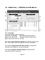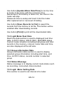
1
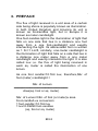
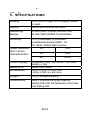
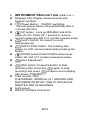
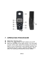
Data Logger Light Meter
TM-203
HB2TM2030000
CONTENTS
1. Description.................................................... 1
2. Safety Precaution ......................................... 1
3. Preface ......................................................... 2
4. features......................................................... 3
5. Specifications................................................ 4
6. Instrument Description (See Fig.1) ................. 5
7. Operation Procedure .................................... 6
8. Relative Spectral (SENSITIVITY).................. 8
9. Attention........................................................ 9
10. Recommended Levels of Illumination ......... 10
11. Battery Replacement .................................. 12
12. Setup User end........................................... 12
13. User end manipulation menu ...................... 13
14. Procedure to install USER END Software .......... 15
15. End of life ..................................................... 15
TM-203
1. DESCRIPTION
Measures light from visible luminaries equipped
with fluorescent, metal halide, high-pressure
sodium and incandescent sources.
2. SAFETY PRECAUTION
CAUTION
Take extreme care for the following
conditions while measuring
Do not operate the meter under the environment
with explosive gas (material), combustible gas
(material) steam or filled with dust.
In order to avoid reading incorrect data, please
replace the battery immediately when the symbol
” appears on the LCD.
“
In order to avoid the damage caused by
contamination or static electricity, do not touch the
circuit board before you take any adequate action.
Operating Environment: Indoors use. This
instrument has been designed for being used in an
environment of pollution degree 2.
Operation Altitude: Up to 2000M.
Operating Temperature & Humidity: -10℃ ~ 50℃,
0%~ 80%RH.
Storage Temperature & Humidity: -10℃ ~ 50℃,
0%~ 70%RH.
EMC:EN61326(1997)+A1(1998)+A2(2001)
EN-1
TM-203
3. PREFACE
The flux of light received in a unit area of a certain
side being shone is popularly known as illumination.
In both United Kingdom and America its unit is
known as footcandles light, but in Europe it is
known as meter candlelight.
One foot-candles light is the illumination of light that
falls on one side that lies in a distance one foot
away from a one foot-candlelight and exactly
intersecting the light. Its abbreviated form is written
as 1 Fc=1 Lm/ft, similarly, one-meter candlelight is
the illumination of light that falls on a side that lies in
a distance one meter away from a one meter
candlelight and exactly intersects the light. It is also
called Lux i,e. the flux of light being received in
each sq. meter is called the illumination of one
lumen.
As one foot candle=10.764 Lux, therefore,Nbr. of
foot (meter) candlelight =
Nbr. of Lumen
──────────────
Area(sq. foot or sq. meter)
Nbr. of Lumen=Nbr. of foot (or meter)x area
Foot-candle/Lux conversion
1 foot-candle=10.764 lux
1 lux=0.09290 foot-candles
(sq, foot or sq. meter)
EN-2
TM-203
4. FEATURES
Overload Indication: LCD will show “OL” in the left
highest position.
Low battery Indication.
Sampling Rate: 2.5 times per second for digital
display.
Spectral response close to CIE luminous spectral
efficiency.
Cosine Angular corrected.
According to JIS C 1609:1993 and CNS 5119
general A class Specifications.
Measuring lights source include all visible.
Measuring intensities of illumination in Lux or
footcandles.
Many applications include: Warehouses, factories,
office buildings, restaurants, schools, library,
hospitals, photographic, many video, parking
garages, museums, art galleries, stadiums, building
security.
Data hold.
Zero adjustment.
Large integrated circuit design.
Auto power off.
Auto range.
Data logger.
Maximum hold.
Minimum hold.
Average hold.
Logger stores up to 7000 values.
EN-3
TM-203
5. SPECIFICATIONS
Display
Sensor
2000 count, large LCD display, easier
to read.
Silicon photodiode and filter
Measuring
Range
20,200,2000, 20000,200000 Lux
20,200,2000,20000 Footcandles
±3% (Calibrated to standard
incandescent lamp 2856∘K)
6% other visible light source,
○
Angle deviation
30
±2%
from cosine
○
60
±6%
characteristics
Accuracy
80
Power Supply
Battery life
Dimensions
○
±25%
9V NEDA 1604, IEC 6F22, JIS 006P
battery x 1pc
About 200 hours
38 (H) x 55(W) x 172(L) mm
1.5(H)x 2.2(W) x 6.8(L) inch
Weight
250 g (include battery)
Accessories
User’s manual,carrying case,9V
battery,RS-232 transmission line,User
End Setup CD
EN-4
TM-203
6. INSTRUMENT DESCRIPTION (SEE FIG.1)
Display(LCD): Display measurements and
function symbols.
Power Button: ON/OFF switching.
The auto power will be off automatically after 5
minutes idle time.
UP button : Lock up MIN,MAX and AVG
value of LCD. Press UP 1 second to resume
normal measuring and LCT number upward setup.
Lux/Fc button: For select Lux and
footcandles (fc)
DATA HOLD button: The reading data
shown on LCD can be locked while pressing the
button.
DOWN button:Press DOWN cancel Auto
Power off and LCT number downward setup.
Zero Adjustment.
REC button: Press the button to start
recording data and press
again to stop
recording and press
to leave record display
with shown “PRESENT”.
Total records 7000
THE MINIMAL INTERVAL IS 1 SECOND AND
MAXSIMUM INTERVAL TIME IS 7HOURS 59
MINUTES AND 59 SECONDS.
Light sensor
RS-232 Interface Connector.
EN-5
TM-203
Fig1.
7. OPERATION PROCEDURE
Open the carrying case.
Press the
button to turn power on or off
Remove the cap of the light sensor, Put the light
sensor at the spot where the testing of source of
light is to be conducted, auto testing will then be
conducted by the meter, read the testing value
after the reading indicated becomes stable.
EN-6
TM-203
If you want to keep the reading value on the LCD
permanently after testing, press the
Key
whereby the reading value will be locked
permanently up. Press the
Key once again
when you want to release the previous locking.
After testing, put the cover of the light sensor
back to its former position, and turn off the switch.
Press the
button for the zero adjustment if
any digits is appeara .
NOTE.:When the light sensor cap is not
attached “CAP” is indicated. Make sure that it is
attached.
If performing the zero adjustment after powering
on, several digits may not disappear. In this case,
perform the zero adjustment again.
LCT setting : Press both
and
at the
same time more than 1 second, LCT will start to
flash. It reminds the user that LCT can be
modified now. Then release the pressing from the
two buttons, press
button to reduce the
numeral, Press
button to increase the
numeral, Then press
to finish the setting.
The numeral’s changing of LCT’s(location) means
the user can use Logger Stores in different places.
Different numeral presents the different place.
Connect to the computer when record finishing.
The numeral of “Logger stores” will be shown on
the right-down side of “USER END
MANIPULATION MENU”.
EN-7
TM-203
8. RELATIVE SPECTRAL (SENSITIVITY)
The deviation from the comparative standards for
luminosity is determined by JIS standard C 16091993.
Peak sensitivity wavelength:550nm
REL ATIVE SE NSITIV ITY(% )
Typ. Ta=23℃
100
80
V(λ)
*
60
TM-203
40
20
0
380 440 500 560 620 680 740
WAVELENGTH (nm)
*CIE luminous spectral luminous
EN-8
TM-203
9. ATTENTION
set for referring the testing of source of light is
located at the right top end (0 degree) of the light
sensor ball plane. (See fig. 2)
When the meter is not in use, please keep the
cap of the light sensor in its place to avoid the
photo diode from wearing out.
When it is not in use for a long time, please take
the batteries away. And avoid keeping it in a
place of high temperature and humidity.
Fig2.
EN-9
TM-203
10. RECOMMENDED LEVELS OF
ILLUMINATION
Suitable levels of illuminance
(According to the JIS standard Z 9110-1979)
Offices
Illuminance (lux) Place
1500 to 750
Offices, designing, drawing rooms
750 to 300
Offices, conference rooms, computer
rooms
300 to 100
Workrooms, corridors, stairways,
restrooms
Indoor emergency stairways
75 to 30
Factories
Illuminance (lux) Place
3000 to 1500
1500 to 750
750 to 300
Where such work as assembling,
inspecting testing, selecting,
extremely precision visual work
Assembling, inspecting, testing,
selecting, precision visual work
300 to 150
Assembling, inspecting, testing,
selecting and visual ordinary work
Wrapping and packing
75 to 30
Indoor emergency stairways
EN-10
TM-203
Schools
illuminance
(lux)
1500 to 300
750 to 200
300 to 75
75 to 30
10 to 2
Place
Precision drawing or drafting,
precision experimenting, library
Classrooms, library reading rooms,
staff rooms, gymnasia
Lecture halls, assembly rooms,
locker rooms, corridors, stairways
and restrooms
Warehouses and emergency
stairways
School passages
EN-11
TM-203
11. BATTERY REPLACEMENT
WARNING
If the symbol ”
” appears on the LCD,
please replace the battery immediately
Remove the battery cover
Replace the battery.
Install the battery cover.
12. SETUP USER END
The User End package contains
Custom designed RS-232 cable for User End
System Required
Windowns 2000, Windowns XP
Minimum Hardware Required
Pentium III 500MHZ PC compatible,or above 128MB
RAM ;At least 10MB hard disk space available to
install User End program.Recommended display
resolution is 800X600 or above
EN-12
TM-203
13. USER END MANIPULATION MENU
13.1 Tool Bar
Tool bar section has 6 buttons:
[Connect To Meter]
[Download All Records]
[Erase All Records]
[Update Meter Date/Time]
[Save Records to File] [Print]
Use button [Connect to meter] to connect meter and
PC. This step is the first step to use this software.
Use button [Download All Records] to download
records from Meter to Local computer.
Use button [Erase All Records] to erase all the
records saved in memory.
EN-13
TM-203
Use button [Update Meter Date/Time] to let the time
in meter to be same with the computer time.
Remember if the battery is taken out, the clock in the
meter will stop.
Please do time re-setup and load it into the meter
after replacement or removed of battery.
Use button [Save Records to File] to export the
records from the list box to txt file. This button will be
enabled after downloading records.
Use button [Print] to print all the downloaded data.
13.2 Light Meter Real Data
Real time data section is used to displayed real time
data, LUX/FC status, HOLD, REC, MAX/MIN status.
Current meter situation including total group and total
records in the memory, interval, meter date and time,
are also displayed at the left side.
13.3 Group information Data
Group information data section is used to display
selected group information including start time, end
time, LUX/FC status, records number in selected
group.
13.4 Status Message
Status message is to display current mete status such
as recording, connected, disconnected,
13.5 Light Meter Setting Data
This section is used to set interval into meter.
EN-14
TM-203
13.6 Records Data
Data will be downloaded into this section after
[download records] button is pressed.
13.7 Connected Signal
The light is used indicated connection status. Green
means connected, red means disconnected.
14. PROCEDURE TO INSTALL USER END
SOFTWARE
1. Place the setup disc into the CD-ROM.
2. Double click “Setup.exe” in the CD-ROM.
3. After finishing setup process, go to start--all
program-“Data Logger\Light Meter\LightMeter
“to run the program.
15. END OF LIFE
Caution: this symbol indicates that
equipment and its accessories shall be
subject to a separate collection and
correct disposal
EN-15
TENMARS ELECTRONICS CO., LTD
6F, 586, RUI GUANG ROAD, NEIHU,
TAIPEI 114, TAIWAN.
E-mail: [email protected]
http://www.tenmars.com