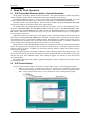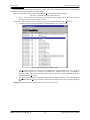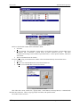
1
AES-IntelliTrak Vehicle Tracking System USER’S MANUAL AES Corporation 285 Newbury Street. Peabody, Massachusetts 01960-1315 USA Tel (978) 535-7310. Fax (978) 535-7313 Copyright 2005 All Rights Reserved Internet: www.aes-intellinet.com AES Corporation 40-7500 Rev. D email: [email protected] August 2005. Version 1.2.2005 VLS-Tracker Contents Contents 1 Product Description .............................................................................................3 1.1 Overview .............................................................................................3 1.2 AES IntelliTrak....................................................................................3 2 General ................................................................................................................4 2.1 System Configuration ..........................................................................4 2.2 System Requirements ..........................................................................6 2.3 Communications (VLS-Server <-> VLS-Clients) .................................6 2.4 Data Entry Basics - Using the User Interface ......................................7 3 Program Installation ............................................................................................8 3.1 Before You Install IntelliTrak Software ..............................................8 3.2 System Installations notes and hints: ...................................................9 3.3 Installing Streets On A Disk...............................................................10 3.4 Installing VLS-Tracker Programs......................................................10 4 Program Setup and Configuration .....................................................................11 4.1 Setting Up VLS-Tracker....................................................................11 4.2 Paths Setup.........................................................................................11 4.3 Setting Up Streets On A Disk.............................................................14 4.4 Communications Setup - Server ........................................................15 4.5 HASP .................................................................................................18 5 Un-installing the Programs ................................................................................18 5.1 Uninstalling VLS-Tracker software ...................................................18 5.2 Uninstalling Streets On A Disk ..........................................................18 5.3 AES Net7000 Software Setup............................................................19 6 Customer Maintenance and Configuration ........................................................20 6.1 Customer Maintenance ......................................................................20 7 Vehicle Maintenance and Configuration ...........................................................22 7.1 Vehicle Maintenance .........................................................................22 7.2 Vehicle Assignment...........................................................................27 7.3 Map Vehicle Display Options Control...............................................29 7.4 Operators ...........................................................................................30 8 Stand By Mode Operation .................................................................................33 8.1 VLS-Tracker Main Window Interface - General Information ...........33 8.2 VLS-Tracker Desktop........................................................................33 8.3 Starting & Closing the Streets On A Disk Program ...........................35 8.4 Sending Messages to Vehicles,..........................................................36 8.5 Printer Setup ......................................................................................37 8.6 Exit the Program ................................................................................37 8.7 Incoming Messages Display Control .................................................37 9 Geographical Data. ............................................................................................37 9.1 Options...............................................................................................47 9.2 History Playback................................................................................49 10 Generating Reports ............................................................................................52 10.1 Report Types & How to Get Them....................................................52 10.2 Protocol Archiving.............................................................................54 11 Bibliography ......................................................................................................55 AES Corporation 40-7500 Rev. D –2– August 2005. Version 1.2.2005 VLS-Tracker Product Description 1 Product Description 1.1 Overview Congratulations on your purchase of AES-IntelliTrak™ for Windows! The AES-IntelliTrak™ system is used to monitor mobile assets over a private wireless AES IntelliNet based network. Vehicles equipped with an AES Vehicle Tracking Transceiver such as the AES 7555-RT send Vehicle Location System (VLS) data to an AES receiver, which passes the data to an AES IntelliNet Radio Management software package. The Management software then extracts the VLS data and stores it in a file located in a shared folder where an AES Tracker Server software can retrieve it and make it available to the local mapping program or a remote client running AES Tracker Client. Tracker Clients can communicate with the Tracker Server using a TCP/IP connection or a standard dial up modem. Likewise the Tracker Server or a Tracker Client through the Tracker Server can be used to send various types of data or requests to the Vehicle Tracking Transceivers. VLS-Tracker operates with the Klynas Streets On A Disk software. Klynas Engineering (www.klynas.com) reserves all rights for the Streets On A Disk software. «Streets On A Disk™» is a registered trademark of Klynas Engineering. It is a full featured mapping software, which includes full search capabilities, the ability to overlay database or other custom information on the map, and a professional map editor. Also featured is a router that can automatically create delivery groups, optimize a travel agenda, and give written travel directions (with distance, time, fuel usage, etc.). An electronic geographic regional map in a format supported by Streets On A Disk is required. Maps are not supplied with AES-IntelliTrak. See “Klynas Engineering. “Streets On A Disk User’s manual”. Key functions of the AES-IntelliTrak system: Using the programmer’s interface of Streets On A Disk, AES-IntelliTrak can place icons or Tokens on a map representing the location of mobile assets. • Display alarm messages for inputs activated on the VLS unit. • Display text messages entered at the VLS unit using a serial terminal. • Send text messages to a VLS unit to be displayed on the local terminal. • Display exceeded velocity alarm message sent by the VLS unit. • Display motion alarm messages sent by the VLS unit indicating unauthorized motion based on time. • Display alarm messages indicating the VLS unit has entered or exited an area defined by one of six geographical areas defined by GPS coordinates. • Request the current status of the VLS unit including location and off normal conditions of inputs. • Send programming data to define the motion time and geographical exclude and include areas. • Send programming data to define time period for reporting GPS location information. • Send instruction to momentarily activate one of two or both relays in the VLS unit. • Current location, trace or alarm points displayed for each vehicle separately. • Vehicle movement and alarm history playback. Vehicle location accuracy is dependant on the GPS-receiver type and the number of GPS satellites in the navigation system for which a signal is available at the time a reading is taken by the VLS unit. • Please refer to the README.TXT file on your Tracker Installation CD-ROM included with the package for the most recent additions and changes to the manual. Read the entire manual and all the materials attached carefully before getting started! 1.2 AES IntelliTrak The vehicles with installed VLS subscriber units (AES 7550, AES 7555-RT) serve as a source of geographic information and alarm messages within IntelliTrak. The events and current coordinates are forwarded to the AES IntelliNet head end and processed. Next using the data exchange files the information is transmitted to the PC with AES-IntelliTrak™ Server Software (AES 7500) also known as VLS-Server installed. You may find detailed information about AES IntelliNet in the appropriate documentation. AES Corporation 40-7500 Rev. C –3– August 2005. Version 1.2.2005 VLS-Tracker General 2 General 2.1 System Configuration Fig. 1 System configuration Fig. 1 illustrates one possible AES IntelliTrak system configuration. This configuration, has at the AES IntelliTrak provider location one PC, with MS-DOS 6.22, a network card, a network client and the AES IntelliNet Radio Network Management software. The other PC at the same location is a Windows PC with a network card, Network server software, Network Client, Streets on a Disk mapping software and Tracker Server software. The figure also shows the location of the VLS-Tracker Client programs. Please note that VLS-Tracker Server may be used without VLS-Tracker Client but not visa versa. VLSTracker Client retrieves information from VLS-Tracker Server only. AES IntelliTrak provider operates the VLS-Tracker Server that is directly connected via the network components to the AES Net 7000 PC. The VLS-Tracker Server contains a database with information on each assigned client, customer’s vehicles and their status. Each client contains its own database of assigned vehicles, which is updated when the client connects to the server. The vehicle’s data and status stored in the both the client and server databases are synchronized during the connection. The server and clients may communicate with each other either via TCP/IP or by dial up modem. The connections may be mixed meaning both connection types may be used where one connection type shall become primary and the other will be used as back up. Don’t confuse Tracker Server with Network Server or Tracker Client with network Client.. The network software is used in this system to share data exchange files between the Tracker software and the AES Net7000 software on a separate DOS PC. Tracker Server is used to share Tracker data with Tracker Clients. A type of Tracker Client is incorporated in Tracker Server so you can view data on the PC using Streets on a Disk. Remote Tracker Clients share data either over a modem or TCP/IP Intranet or Internet connection. AES Corporation 40-7500 Rev. D –4– August 2005. Version 1.2.2005 VLS-Tracker General Fig. 2 Data flow chart (#)’s referenced in text below The system data exchange scheme is shown in Fig. 2. As may be seen from the drawing the clients interact with their vehicles via VLS-Server. Data exchange occurs as follows. The AES Net7000 has a 2-way communication link with vehicles via an AES IntelliNet receiver. It receives messages from vehicles or sends commands or messages to them. The VLS-Server performs data exchange with the AES Net7000 PC by means of special exchange files. The VLS-Server gets GPS, alarm and text messages [(1) – from Fig 2 above] from the AES Net7000 PC. Messages are appended into the database of the VLS-Server and forwarded to the appropriate clients depending upon a vehicle assignments. The VLS-Server on a clients’ request (or on its own) may send text messages or GPZ (Geographic Zones Programming) commands to the corresponding vehicles (2). There may be five data exchange types between the VLS-Server and clients. They are listed below: • GPS (vehicle location) and alarm messages (3) are transmitted from the VLS-Server to the appropriate clients. These messages reflect the current vehicle status. • Text messages and GPZ commands (6) may be transmitted bi-directional. If a text message comes from a vehicle, the AES Net7000 PC will forward it via VLS-Server to the corresponding customer’s Client. A customer may also send a text message to his vehicle. • A client may query the VLS-Server for historical GPS, alarm and text data stored in its database for a certain time period. (4). • In response to the client’s data query (4) the VLS-Server sends the requested data (5) for the time period specified by the client. • Updating client’s database (7) by adding or deleting vehicles. When an administrator registers a new vehicle on the VLS-Server and assigns it to a customer, all vehicle data is transmitted to the appropriate customer’s database on a Client. Specifically data synchronization occurs and any new vehicles are automatically recorded in the customer’s database. These operations are performed, for example, when a customer installs a new VLS unit on a vehicle. The same synchronization occurs when an administrator deletes a vehicle or withdraws vehicle assignment from a customer (7). An authorized user with administrator rights at the VLS-Server creates customer accounts with an administrator ID and password. An administrator at the VLS-Server performs vehicle assignments. An administrator at the client must configure the TCP/IP (Internet) and/or dial up modem parameters for data exchange between the server and customer. Any attempt to exchange data between a client and server must first be authenticated by the VLS-Server. All data is encoded between client and server. Once authenticated, the provider performs the following functions: • Maintenance of internal database updating each vehicle’s current status (GPS, last alarm state data); • Updates database with vehicles data received since the last connection by the client; • Retrieves programming changes requested by the client for transmittal to VLS units; • Interaction of VLS-Server with Net7000 Software for data exchange. AES Corporation 40-7500 Rev. C –5– August 2005. Version 1.2.2005 VLS-Tracker 2.2 General System Requirements VLS-Server and Client software packages must be installed on the IBM-compatible PC with the following minimum requirements: • Intel Pentium 133 MHz CPU or higher; • 128 MB RAM; • 2 GB HDD with at least 240 MB free disc space after operating system installation; • CD-ROM 2x or faster; • SVGA with 2 MB RAM Graphic Controller; • SVGA Monitor with 1024х768x65Hz resolution; • Keyboard and “mouse”; • Windows 2000/XP Professional; • Streets On A Disk GIS-package. • Depending on the selected configuration, a Network environment consisting of a Network Server with both Windows & DOS Clients for Connecting VLS-Server to the Net7k DOS Computer, for the purpose of sharing data exchange files. The requirements are subject to change due to operating system requirements and configuration of AES IntelliTrak. It is in no way recommended to operate with the minimum system requirements. Processor speed and installed memory will directly impact the usefulness of the system. In general you must be guided by the following recommendations: • The best selection for VLS-Server is a specialized server with the redundant disc subsystem (RAID) and redundant hot-swappable power supply. • The VLS-Client operates most efficiently on workstations under Windows 2000 Professional or XP Professional. • The RAM size considerably effects the system’s hard disc access speed and, consequently, overall system performance. • For the convenient and safe work environment for an operator, we recommend using SVGA monitors with a screen size not less than 17”. Being an integral part of the system, communication options and the AES IntelliNet system are described in separate chapters (“General” – “Communications” and “General” – “AES IntelliTrak”). 2.3 Communications (VLS-Server <-> VLS-Clients) The VLS-Tracker package supports communication between the VLS-Server and VLS-Clients using two types of communication methods. Available options are dial up modem and TCP/IP connections. Each customer may use either type of communication or both to establish a primary and back up data transmission channel. 1. Dial-Up Connections. The dial-up connection between a client and a server is maintained over telecommunication networks providing a data transmission service via modems. The program supports only standard HAYES-compatible modems to be operated on dial-up lines connected to PC via ASYNC Serial Ports. We recommend using modems supporting at least V.34 data transmission protocol and operating at a minimum of 33.6 Kbps. The amount of data transmitted is not all that great, but data transfer delays and communication failures may be more common at slower rates where an incoming line is occupied by clients for long periods of time. For more information about modem types, connection and setup refer to the section “Program” – “Communications Setup - Server”. 2. TCP/IP Connections. TCP/IP is a standard protocol used by different communication devices and operating system. Windows on both VLS-Server and VLS-Clients must support TCP/IP protocol. Usually, TCP/IP is configured when client’s PC is connected to the server via Local Area Network or Wide Area Network. For detailed information about communication setup via TCP/IP protocol refer to the section “Program” – “Communications Setup - Server”. AES Corporation 40-7500 Rev. D –6– August 2005. Version 1.2.2005 VLS-Tracker 2.4 General Data Entry Basics - Using the User Interface This section covers the principles of working with the graphical interface as well as specifying some of the terms used in throughout this Manual. Understanding and experience using the above-mentioned operations permits an operator to perform the main user tasks on a client’s PC. Press F1 key means that it is necessary to press the indicated key (F1) on the PC keyboard. Hot key information is often described in this way allowing quick access to the appropriate program function. Fig. 3 shows the basic elements of the user interface window. Described below are the main operations, which you will find throughout this manual. Choose menu item File means that you need to enter the menu in the upper part of the window using your mouse or keyboard, find the required item, mark it with the mouse cursor or highlight with a bar using navigation keys and select it by clicking on the left mouse button or pressing Enter key on the keyboard. This instruction may be followed by an explanation in which submenu to select an indicated item. Enter TEXT into edit box. Position the cursor into the rectangular area of the edit box and type the required text on the keyboard. Click on OK Button – click with the mouse left button on the indicated button located in the user interface window. Check (uncheck) the check box – place/remove the mark symbol (usually a cross) in the mark field square by clicking on the mouse left button on it. Fig. 3 Illustrates a Window sample that utilizes all data input types used AES Corporation 40-7500 Rev. C –7– August 2005. Version 1.2.2005 VLS-Tracker Program Installation 3 Program Installation 3.1 Before You Install IntelliTrak Software AES IntelliTrak is a combination of hardware and software integrated into a complete system to add monitoring and tracking of mobile assets to AES IntelliNet. Before attempting to install VLS-Tracker Server software on your Windows 2000/XP Professional PC, it is essential that other equipment and software of the AES IntelliTrak system be in place. In order to achieve a successful installation the equipment and software must be properly installed, configured and operational. Refer to the list below for a summary of those items. 3.1.1 An operational AES IntelliNet System and infrastructure. Visit our web site at http://aes-intellinet.com. That system would be built on the following: a. An AES IntelliNet Receiver: (7003, 7000/2, 7703*, 7701*, Sys99, 7001, etc.) * UL receivers support IntelliTrack but, not authorized for use by UL or AES b. Stationary Subscriber installations covering the desired vehicle tracking coverage area. There should be a sufficient network in place to enable vehicles to communicate to at least one subscriber at nearly all traveled locations within that area. c. AES Network Management software (Net7000) operational and properly connected to the AES receiver. i. This has traditionally been installed on a dedicated MS-DOS 6.22 PC. Depending on your purchase this PC may or may not have been provided by AES. ii. We have tested the configuration that will operate the DOS Net7000 software on the same Windows 2000/XP Professional PC as the VLS-Tracker Server software. This is the preferred configuration. 3.1.2 Windows 2000/XP Professional PC - A PC with Windows 2000/XP Professional operating system. Due to recent program modifications and testing other Windows operating systems are no longer supported for the VLS-Tracker Server. As stated in 1.a.ii. above, this PC may be able to run the Net7000 in a virtual DOS window. 3.1.3 Computer Network Environment - If the AES Network Management software (Net7000) is running on a dedicated MS-DOS PC then a computer network to connect the two PC’s for sharing data exchange files is required. (Not provided by AES) a. b. c. d. Because there are number of possible configurations that can accomplish the required file sharing capability, AES will only attempt to provided detailed setup information for a select few options. The goal of any of the mentioned or unmentioned configurations is to provide a folder or directory where the Net7000 program and the VLS-Tracker Server can exchange files. A network includes but is not limited to: A network operating system, Network Interface Cards (Ethernet) for both PC’s, network cabling, Server and client software. i. The network can be a Client / Server or Peer-to-Peer based network. The selected network must have client software available for both the Windows 2000/XP and the DOS operating systems. ii. Network environments tested by AES are Novell (http://www.novell.com/) and LANtastic (http://www.spartacom.com/). Recently AES became aware of and performed preliminary testing on a Microsoft Network Client 3.0 for DOS that can access Microsoft networking. iii. Any configuration you can come up with that allows the two programs to exchange files and also does not interfere the running of Net7000 is potentially a viable option. AES can only be expected to provide minimal advice on a configuration for which we have not listed the setup steps. Your network client installed on the DOS PC must be loaded into upper memory to ensure there is enough conventional memory for the AES Net7000 program to run. MEMMAKER is a DOS utility that can be used to configure your PC and determine what programs can be loaded into upper memory adding the appropriate commands to your startup files. Type “HELP MEMMAKER<Enter>” at the DOS prompt for additional info. Your Network software must be operational and automatically started at boot-up before running MEMMAKER. AES Corporation 40-7500 Rev. D –8– August 2005. Version 1.2.2005 VLS-Tracker Program Setup and Configuration 3.1.4 Streets on a Disk mapping software, and maps of your coverage area. (May be provided by AES). Read “Introduction” in Tracker user’s manual. a. Visit Streets on a Disk web site http://www.klynas.com/ b. Maps for the USA are readily available and can be purchased from Klynas along with your Streets on a Disk software. c. For maps outside the USA there is an import utility within Streets on a Disk that can import Shape files. Shape files are widely used by many mapping software products. For additional information on Shape files visit: http://software.geocomm.com/translators/ (Non USA maps not provided by AES) d. It is highly recommended that you also subscribe to support for Streets on a Disk from Klynas Engineering. http://www.klynas.com/. This is extremely important if you need to import a shape file, as you will need their assistance during this process. 3.1.5 3.2 IntelliTrak software CD with HASP software security key. (Provided by AES) System Installations notes and hints: 3.2.1 The order of the items listed in “Before You Install IntelliTrak Software” is essentially in the order that should be followed during installation. Do not move to the next item until each is completed in turn. Although some items could be setup out of order others cannot and usually result in an unsuccessful installation. 3.2.2 Item 1 (AES IntelliNet System) above, should have been completed long before you begin the setup of your IntelliTrak System. If you are attempting to setup an initial IntelliNet system at the same time as IntelliTrak, you should first become familiar with IntelliNet before attempting the IntelliTrak installation. 3.2.3 Refer to documentation for minimum requirements of the PC’s needed in the IntelliTrak system. a. b. See “General” – “System requirements” in this users manual. Net7000 runs on a 66 MHz 486 or better but also consider the minimum requirements of your network client software and hardware. The PC must have at least one serial port but two is recommended to utilize some features of Net7000. 3.2.4 Install and connect your NIC’s (Network Interface Cards) before installing the network software. If only connecting two PC’s together without need to access the Internet you can use a CAT5 Crossover cable between the two NIC’s. Otherwise a HUB or switch is needed. Consult a network specialist for assistance. 3.2.5 LANtastic Network configuration Note. a. You only want LANtastic client installed on the DOS PC. During installation do not select to share drives and printers. You should create a permanent mapped drive pointing to a dedicated folder for sharing data exchange files. A suggestion is “\TDATA”. AES Corporation 40-7500 Rev. C –9– August 2005. Version 1.2.2005 VLS-Tracker 3.3 Program Installation Installing Streets On A Disk Before installing streets you should have items 1 through 3 in “Before You Install IntelliTrak Software” completed. VLS-Tracker software operates together with Streets On A Disk map program. Streets On A Disk program may be installed either before or after VLS-Tracker setup, but VLS-Tracker should not be run for the first time until after Streets On A Disk is installed. Therefore it is highly recommended that Streets On A Disk be installed before VLS-Tracker. Streets On A Disk software must be installed in the following order: 1. Insert the Streets On A Disk installation CD-ROM in the CD drive or diskettes in the FDD. 2. Launch SETUP.EXE from the installation media. 3. Then follow the instructions of the installation wizard. 4. Use default settings in the Streets On A Disk installation wizard. Install it in the suggested folder. 5. When installation is completed, restart the computer. At this time you may run the Streets On A Disk program if you wish and select the map(s). All of the Streets On A Disk configurations cannot be completed until VLS-Tracker is installed. 3.4 Installing VLS-Tracker Programs 1. Insert the HASP key (supplied with the installation kit) into the parallel port of your PC. Note: XP Professional may need the latest HASP update to support our software key. The file HardlkXP32.zip is located on the Tracker CD. It is a Win32 HASP Device Driver (GUI) Installation Utility (Version 4.85). Unzip the files to a temp folder on your hard drive and read the readme.txt file. Then run the HDD32.exe driver installation program which was unzipped to the same location. Note: Windows XP can only be used with the Tracker Client Software. 2. Insert installation CD. 3. Setup should start automatically. If Setup does not start automatically, start the program using Setup.exe on the installation CD. 4. If the Windows Explorer window does not open to a full screen view, click maximize button in the upper right corner of the window to display in full screen. 5. Click “Install” on the left side of the window. 6. Select “Run Program from its current location.” Then OK. 7. Select “Yes” to “Do you want to install and run ‘setup .exe’ from …” 8. Read the license and select “Yes” to the license agreement. 9. Please read the displayed Information text and then select “Next”. 10. Enter customer information including serial number and then select “Next”. 11. Select “Next” to choose default destination location. 12. Select Setup type “Typical” and then “Next”. 13. Accept “VLS Tracker” for the program folder by selecting “Next”. 14. Review setup information and select “Next” to accept. 15. Select “Next” for the “HASP Device Driver Installation”. 16. Select “Next” for “Installation Status”. 17. Select “Next” for the “HASP Device Driver Installation” Finished. 18. Select “Finish” for “VLS Tracker Setup Complete” 19. After installation program finishes, it is best to restart the computer at this time to let any changes made take effect. AES Corporation 40-7500 Rev. D – 10 – August 2005. Version 1.2.2005 VLS-Tracker Program Setup and Configuration 4 Program Setup and Configuration 4.1 Setting Up VLS-Tracker To set up VLS-Tracker software use Setup submenu of the VLS-Tracker desktop. (Shown in Fig. 4) Fig. 4 Submenu Setup It is recommended that the setup be performed in the sequence listed below. The following settings are mandatory for basic system operation. If operating only on the local system without connecting to a remote VLSClient then the “Communications parameters setup (Server menu function)” can be configured at a later time. • Path setup to the system files (Paths menu function). See figs. 5a & 5b below. • Communications parameters setup (Server menu function). Used by remote VLS-Client. Contains IP and Modem configuration parameters for connection between VLS-Server and VLS-Clients. • List input of the existing customers (Customers function). Must create at least one. • List ID’s of the monitored vehicles (Vehicles menu function) and their assignment to the customers (Vehicles assignment menu function). The other settings are not compulsory to run the program after its installation. Provided below is detailed descriptions of dialog windows opened by functions in the Setup menu. 4.2 Paths Setup Shown in Figs. 5a & 5b are examples of the window opened by the Paths… function in the Setup menu. Data in the fields shown in Fig. 5a are appropriate for a configuration that uses a Mapped virtual drive labeled H: on a Network connecting the VLS-Tracker Server to the Net7000 PC as described in examples this manual. Data in the fields shown in Fig. 5b are appropriate for a configuration that has VLS-Tracker Server and Net7000 on the same Windows 2000/XP PC. Note: If the AES Network Management software (Net7000) is running on a dedicated MS-DOS PC, then your Tracker Server Windows computer must have a virtual drive (e.g.: H:) that’s mapped to your Network Server’s shared drive. In a system that is using LANtastic network software on the same Windows PC as Tracker Server, your Tracker Server PC will also be your LANtastic server and needs the LANtastic client configured and mapped to a shared folder. One possible configuration would be to create a folder on drive C: of the Windows PC that is also the LANtastic server and give it a name such as “TDATA”. Then map your LANtastic clients to that folder so that whatever drive letter you select, H: in this example equals that folder. Then simply using the drive letter H: will point the software to the shared folder and the examples shown in Fig. 5a can be used. Also Net7000 software needs to point at the same shared folder through its network client, preferably using a simple drive letter such as H:. AES Corporation 40-7500 Rev. C – 11 – August 2005. Version 1.2.2005 VLS-Tracker Program Installation Fig. 5a System files location setup – Network Configuration. Paths may be directly entered into the appropriate field or selected using the Browse function. To activate the Browse function click the button “...” to the right of the field. The paths to the GIS command file and GIS response file are set automatically. The paths of these files may be changed from the Streets On A Disk program only. Start Streets On A Disk and select the Main Options… command in the Options menu. Select Misc in the displayed window. Set up the required paths in the Programmer's Interface / GPS window. Make sure that the On/Off checkbox is set in this window. The paths setup in the Database file as well as in the map file of this window do not effect program operation and is purely informative. The Database file is always located in the VLS-Tracker setup directory and map selection is made from Streets On A Disk program. Note: Fig. 5a System files location setup (Assuming H: = \\[servername]\TDATA\) Net7000 data exchange files location examples “Net7K data files location”: (VLS-Server only). From Net7K: To Net7K: H:\GPSDATA.DAT H:\AESCTRL.DAT AES Corporation 40-7500 Rev. D – 12 – August 2005. Version 1.2.2005 VLS-Tracker Program Setup and Configuration Fig. 5b System files location setup – Local 1 PC Configuration Note: Fig. 5b System files location setup (Assuming C: = Local HDD) Net7000 data exchange files location examples “Net7K data files location”: (VLS-Server only). From Net7K: To Net7K: C:\TDATA\GPSDATA.DAT C:\TDATA \AESCTRL.DAT AES Corporation 40-7500 Rev. C – 13 – August 2005. Version 1.2.2005 VLS-Tracker 4.3 Program Installation Setting Up Streets On A Disk After Street On A Disk and VLS-Tracker Server installation you must configure Street On A Disk for common application with the VLS-Tracker Server. To accomplish this, it is necessary to install the map of the intended coverage area and create vehicle tokens to be displayed on the map. To set up Streets On A Disk follow these steps: 1. Run Streets On A Disk (ex. with help of Streets On A Disk shortcut on the Windows Desktop). 2. Once the program is run select the Maps… item in the Main Menu. 3. Place the required maps in the maps list in the appeared window and click on OK button. 4. Now set up vehicle tokens displayed on the map by VLS-Tracker. For this purpose use the “Point Options (Custom…)” function in the Options menu. 5. The dialogue window shown in Fig. 6 will be opened. 6. Enter fixed vehicle state names listed below, in the free lines of the Description column: (numbers 0,1,2 etc. shall NOT be separated from the word State with a blank space): • State0 – normal • State1 – last point before receiving an alarm • State2 – alarm • State3 – alarm restored • 7. State4 – alarm received by an operator Assign state tokens to the appropriate lines in the Style column of the Token frame by double clicking on the Token box under the Style column with the left mouse button. Select a token, its size, angle and fill pattern in the popped up window. Repeat the procedure for all five states. Double click with the left mouse button on the text field in the displayed window to select font (national, if required) and its parameters in the corresponding lines in the Style column of the Text frame. 8. 9. Fig. 6 Setting vehicle state tokens AES Corporation 40-7500 Rev. D – 14 – August 2005. Version 1.2.2005 VLS-Tracker 4.4 Program Setup and Configuration Communications Setup - Server General Information Shown in Fig. 7 is the window opened by Server… function in the Setup menu. Fig. 7 Communications setup. TCP/IP link Select the desired communications type: Modem or IP. Fig. 7 above shows the IP communications setup window. Fig. 8 below show’s the modem communications setup window. Fig.7 above shows the TCP/IP Communications settings used by the VLS-Client to connect to the VLS-Server. Fig. 8 below shows the Modem settings window. Both windows contain the common Description field in which any text may be entered. Both window pull down lists operate in a similar manner. The upper right button from the list allows inserting a new line, the middle one assigns the primary address and phone and the lower button is used to delete the current line. The address and phone assigned as being primary will be used first when establishing communication. The line with a basic element is printed in boldface font. The pop up menu is displayed by pressing the right mouse button in the list field. IP Communications Setup • Attempts - Number Property. This parameter is used to set a number of additional attempts for establishing communication with a client. The parameter value may be within the range of 0..32000. The recommended range value: 1..100 The Default setting is [1]. Optimal setting is (2) • Attempts - Interval Property. This is to set time interval (in seconds) between the attempts to establish communication – if the number of attempts exceeds 0. The parameter value may be within the range of 0..32000. The recommended range value: 1..300. The Default setting is [2]. Optimal setting is (1) • Break Interval - Number Property. It is designed to set break interval (in seconds) to maintain communication without breaking after last message delivery in the given communication session. The parameter value may be within the range of 0..32767. The recommended range value: 0..5. The Default setting is [4]. Optimal setting is (0 – Break Canceled) AES Corporation 40-7500 Rev. C – 15 – August 2005. Version 1.2.2005 VLS-Tracker Program Installation Fig. 8 Communications setup. Modem Modem Communications Setup • Model Property. This option is designed to select the appropriate modem model. If found the Initialization String option is filled automatically. • Initialization String Property. This is used to set the modem initialization string where commands are selected for configuring the modem. If the modem is already set up (the commands have been stored in the current profile) the option may not be installed. • Port Property. Used for selecting COM-port for connection to the modem. Only configured COM ports will be available for selection. • Port Purpose Property. This option may be used to select purpose of using COM-port’s modem. The COM-port may be used for: 1. Incoming connections only (Listen); 2. Outgoing connections only (Dial-up); 3. Both types (Listen / Dial-up). If modem connections are used to transmit messages, it is necessary to select Dial-Up Only or Listener/Dial-Up option in Port Purpose for at least for one COM-port on the Server. AES Corporation 40-7500 Rev. D – 16 – August 2005. Version 1.2.2005 VLS-Tracker Program Setup and Configuration For some Server COM-ports it may be possible to select Listener Only option. It is recommended to do this when you have more than 4 COM-ports and a large number of clients. This helps to reduce waiting time to connect a new client. • Baud Rate Property. This is the selection for the COM-port (bit/sec) rate. The allowable baud rates are: “300, 1200, 2400, 4800, 9600, 19200, 28800, 38400, 57600, 115200”. Choose baud rate greater than maximum possible connection speed of your modem. Recommended: 115200. • Data Bit Property. It is used to select a number of data bits transmitted. The possible value list includes: “8,7,6,5,4”. Choose “8”. • Parity Property. Making a selection of the transmitted data parity control. The possible value list includes: “Odd, Even, None, Mark, Space” Choose “None”. • Stop Bit Property. This is to choose a number of stop bits. The possible value list includes: “1, 1.5, 2”. Choose “1”. • Response Timeout Property. It is used to set a maximum waiting time interval (in seconds) to connect a Client or receive a message acknowledgment. The parameter value may be within the range of 0..32000. The recommended range value: 30..90. The Default setting is [60]. • Attempts Property. This parameter is used to set a number of additional attempts for establishing communication with a client. The parameter value may be within the range of 0..32000. The recommended range value: 1..5. The Default setting is [2]. • Attempts Interval Property. This is to set time interval (in seconds) between the consequent attempts to establish communication – if the number of attempts exceeds 0. The parameter value may be within the range of 0..32000. The recommended range value: 1..3. The Default setting is [1]. • Break Interval Property. It is designed to set break interval (in seconds) to maintain communication without breaking after last message delivery in the given communication session. The parameter value may be within the range of 0..32000. The recommended range value: 1..10. The Default setting is [1]. • Session Time Property. This is used to set a time interval (in seconds) to provide maximum time session for forwarding messages to the clients. The session is forcibly terminated (the connection is broken by the program) if the current session time exceeds the given parameter value. If the Break Interval parameter value exceeds the given value the connection is still broken. The parameter value may be within the range of 0..32000. The recommended range value: 90..180. The Default setting is [0]. AES Corporation 40-7500 Rev. C – 17 – August 2005. Version 1.2.2005 VLS-Tracker 4.5 Program Installation HASP The HASP™ key is used for the following purposes: • Data Transmission Security from Server to Client. • Data Package Integrity. • Customers Authorization. Note: XP Professional may need the latest HASP update to support our software key. The file HardlkXP32.zip is located on the Tracker CD. It is a Win32 HASP Device Driver (GUI) Installation Utility (Version 4.85). Unzip the files to a temp folder on your hard drive and read the readme.txt file. Then run the HDD32.exe driver installation program which was unzipped to the same location. Note: Windows XP can only be used with the Tracker Client Software. 5 Un-installing the Programs 5.1 Uninstalling VLS-Tracker software To uninstall the program package perform the following three operations: 1. Open Windows Control Panel. It may be done by selecting the Settings – Control Panel in the Start menu or clicking twice on Control Panel icon in the My Computer folder. 2. Open Add/Remove program wizard. 3. In the list of the installed programs select VLS-Tracker, click on the Add/Remove button and in the appeared dialog window press the Remove button. 5.2 Uninstalling Streets On A Disk To uninstall the Streets On A Disk program follow these steps: 1. Open Windows Control Panel. It may be done by selecting the Settings – Control Panel in the Start menu or clicking twice on Control Panel icon in the My Computer folder. 2. Open Add/Remove program wizard. 3. In the displayed window select the Streets On A Disk item and press Add/Remove button. AES Corporation 40-7500 Rev. D – 18 – August 2005. Version 1.2.2005 VLS-Tracker 5.3 Program Setup and Configuration AES Net7000 Software Setup • Being a perquisite before installing the Tracker software, Net7000 program should already be installed on the selected computer with a shared folder assigned and configured for sharing data exchange files. For the software components of the AES IntelliTrak system to work together properly some user setup is required. Net7000 is inherently a DOS program, and due to its programming, may have unexpected performance within the Windows 2000/XP Professional environment. Therefore, Net7000 was typically installed on a dedicated MSDOS machine. The single computer configuration has been tested by AES and is now the preferred configuration. VLS Tracker Server and Streets On A Disk are programs which were originally designed for Win9x/2000/XP or NT3.x/4.x. Recent modification limit its installation to Windows 2000/XP Professional operating systems only. As shown in the Fig. 9, Net7000 and VLS Tracker Server operate together by passing data exchange files to each other through a shared folder or directory. This means that the network must contain a drive path, which is visible to both machines. Both programs require the user to identify the path of a folder or directory, which can be used for this purpose. In VLS Tracker, the Path dialog contains a form, which allows the user to select the folder or directory (see “Paths Setup”) Net7000 requires that the user enter this data on the command line the first time that the user runs the program. The program will permanently store the information, so it need not be re-entered each time the program is executed. Fig. 9 Data Exchange between Net7000 and VLS Tracker Server The command line parameters for Net7000 are as follows: from the DOS prompt in the directory, which contains Net7000, type: net7kp /F<shared file path> /G3 NOTE 1: use “net7kf” if you are using the full forwarding version of Net7K. NOTE 2: use “net99” if you have a System 99 and are using the Net99 version of Net7K. Example: running Net7K from the directory C:\AES\ and using H:\ as the shared directory: C:<Enter> To confirm you have selected Drive C: as the active and current drive. CD\AES<Enter> to confirm you are executing Net7K from its installed directory or folder. net7kp /FH: /G3<Enter> In this example, C:\AES\ is the directory path, which contains the Net7000 program, NET7KP is the Net7000 program name and H:\ is the virtual network drive and directory path of the shared directory, which is visible to both machines and will be used to share data files between them. AES Corporation 40-7500 Rev. C – 19 – August 2005. Version 1.2.2005 VLS-Tracker Program Installation 6 Customer Maintenance and Configuration 6.1 Customer Maintenance Shown in Fig. 10 is the window opened by the Customers… function in the Setup menu Fig. 10 Edit customers form The popup windows menus are shown in Fig. 11 and Fig. 12. • The File Menu contains commands for saving changes and closing the window. Fig. 11 Edit customer form. Menu • • Fig. 12 Edit customers form. Popup menu Edit Menu contains a dialogue command of adding a new customer, a command of deleting, editing the customer selected in the list, and a dialog command of opening the window with communications settings of the customer selected in the list. Add Command. The Add Customer window is shown in Fig. 13. You need to fill in all the fields in this window and press Add button. The customer will be added to the customers list in the parent window. Once all customers are entered, click on Close button. Use Clear button to delete all enter fields. AES Corporation 40-7500 Rev. D – 20 – August 2005. Version 1.2.2005 VLS-Tracker • • • • Program Setup and Configuration Fig. 13 Add customer form Update Command. The Edit window for a selected customer is shown in Fig. 14. Once all changes are made, click on OK button. The window will be closed and information in the list changed. Use Restore button to restore initial field data. To close the window and cancel all changes made, click on Cancel button. Connection Command opens the communications properties window for the customer selected in the list. Detailed description of this window is given above in the section “Communications Setup - Se” View Menu has a toggle command allowing to hide/show customers passwords and submenu with sort commands in the similar list columns. A checkmark before the command name corresponds to its current state. Pop-Up Menu replicates the appropriate commands of the main menu. To display the menu click the right mouse button on the field list. Fig. 14 Edit customer form The window list contains in the first column a changeable check box pointing out the state of a customer. The marked customers are handled in a usual way. Data for unchecked vehicles is received and stored, but not forwarded to the customer’s. Client. When removing a checkmark the program always makes a request to confirm a customer disconnection. The column names are command buttons. When clicking on the name button, table sorting begins in the selected column in ascending order. In the status line are displayed ID and name of the selected customer. AES Corporation 40-7500 Rev. C – 21 – August 2005. Version 1.2.2005 VLS-Tracker Program Installation 7 Vehicle Maintenance and Configuration 7.1 Vehicle Maintenance Shown in Fig. 15 is the window opened by the Vehicles… command in the Setup menu. Fig. 15 Edit vehicles form Fig. 16 Edit vehicles form. Menu • • • Fig. 17 Edit vehicles form. Popup menu File Menu contains commands for saving changes and closing the window. Edit Menu. It has a dialog command for adding a new vehicle, a command for deleting the selected vehicle in the list and a dialog command for editing the vehicle selected in the list Add Command. The Add Vehicle window is shown in Fig. 18. A unique Vehicle ID and its name must be entered. Additionally you may select from the opened list the vehicle customer/owner. Keep in mind that a vehicle ID consists of 4 digits in the hexadecimal format. For example, 1AF6. Once you have entered textboxes, click on the Add button. The vehicle added is then place in the vehicle list of the parent window. Having entered all the vehicles click on the Close button. Use Clear button to clear all the textboxes. AES Corporation 40-7500 Rev. D – 22 – August 2005. Version 1.2.2005 VLS-Tracker • • Program Setup and Configuration Fig. 18 Add vehicle form Update Command. This command is used to open the Vehicle Properties window shown in Fig. 19. The window consists of 9 tabs. The General tab’s fields are shown in Fig. 19. DATE: TO: FROM: RE: Heading 3 Fig. 19 Vehicle properties. Tab General • • • • • Checkbox Enabled. Determines the vehicle state. The marked vehicle is handled in a usual way. If it is not marked then the vehicle information is received, stored, but not forwarded to the customer/client. Name Textbox. This textbox contains nametag entered in the vehicle data stamp on the map. The overall vehicle data stamp length on the map does not exceed 24 characters. The vehicle name tag in this textbox coincides with the vehicle name added. Icons frame. Allows configuration of the vehicle tokens displayed on the map. You may determine a token for a normal and alarm state. This feature is not enabled in this version. Data Stamp. Has three checkboxes that are not used in this version. To control the data stamp use Vehicle Display Options opened by the Vehicle Display Options in the Setup menu. Coordinate Input Format Checkbox determines coordinate input format in this frame window. AES Corporation 40-7500 Rev. C – 23 – August 2005. Version 1.2.2005 VLS-Tracker • • Program Installation Checkbox 7555 (MARK II). Selecting this indicates the type of VLS Subscriber Unit used. If the Checkbox 7555 (MARK II) is marked, it means that latest type of the 7555-RT unit is installed in this vehicle and the group of checkboxes in Terminal Modes becomes available. Terminal Modes Checkboxes define the operational modes of the terminal output in the 7555-RT (MARK II). For additional details see in the 7555-RT MARK II Manual. Alarm Velocity tab is shown in Fig. 20. Fig. 20 Vehicle properties. Alarm velocity tab This tab determines the maximum vehicle velocity. Over speed is displayed as an alarm on zone 25. The velocity is entered in miles or kilometers per hour. The velocity format is selected with the help of two radio buttons right from the textbox. The textbox has a tool-tip, which displays the available velocity range. Alarm Velocity Appearance on the Map contains properties that are not used in this version. Motion Time Tab is shown in Fig. 21. AES Corporation 40-7500 Rev. D – 24 – August 2005. Version 1.2.2005 VLS-Tracker Program Setup and Configuration Fig. 21 Vehicle properties. Motion time tab The allowable vehicle motion time interval is entered in these textboxes. Vehicle motion outside the programmed time period is displayed as an alarm on zone 26. • Alarm Appearance on the Map frame contains properties that are not used in the current version. • Zone 27 - Zone 32 tabs have the same structure. These tabs determine six geographic zones supervised by the vehicle subscriber unit. Zone 27 tab in the geographic coordinate input format "degrees-minutes-seconds" is shown in Fig. 22. Zone 28 tab in the geographic coordinate input format "decimal degrees" is shown in Fig. 23. • Description Textbox. The program does not use this internally. It is used to describe a zone for user needs. • South West Point Textboxes (the lower left) and North East Point (the upper right) determine the rectangular area on the map within which a vehicle may be located or not allowed to enter. All text boxes here have pop-up tool-tips with a range of permissible values. AES Corporation 40-7500 Rev. C – 25 – August 2005. Version 1.2.2005 VLS-Tracker • • Program Installation Fig. 22 Vehicle properties. Zone 27 tab Confine/Exclude Frame defines the supervised area as defined by the configured rectangle. The Confine option allows motion within the configured rectangle whereas Exclude option forbids vehicle motion within the configured rectangle. Region Activation Time 1 and Region Activation Time 2 define two time ranges in the course of which vehicle motion is controlled within the configured area. In the text boxes of these frames only enter time as referenced from the beginning of the day. (24 hour clock) AES Corporation 40-7500 Rev. D – 26 – August 2005. Version 1.2.2005 VLS-Tracker Program Setup and Configuration Fig. 23 Vehicle properties. Zone 28 tab • View Menu contains submenu with Sort commands in the list columns. • Pop-Up Menu duplicates the appropriate commands of the main menu. This menu is displayed by clicking the right mouse button on the list. The vehicle list has in the first column a changeable checkbox to determine the vehicle status. The marked vehicles are processed routinely. Vehicle data with removed marks are received, stored, but not forwarded to the customer’s clients. Double clicking with the left mouse button on the list line is equivalent to the Update command in the Edit menu. The column headers are command buttons. Press header buttons for sorting in the selected column in ascending order. In the window status line are displayed ID and Name of the vehicle selected in the list. 7.2 Vehicle Assignment This window is opened by Vehicle Assignment... command in the Setup menu and shown in Fig. 24. This window has a menu, a drop-down customers list, customers tree with their vehicles, an all vehicles list, a pop-up list menu and a status line. There is a window splitter between a tree and a list. When positioning the mouse cursor on the window splitter, the mouse cursor changes its appearance. By pressing the left mouse button in this condition the window splitter may be dragged-and-dropped to the required position. By positioning the mouse cursor on the window boundaries, the window size itself may be changed using the same drag and drop function of the mouse. The window menu and pop-up list menu are shown in Fig. 25 and Fig. 26. • File Menu contains Save changes and Close window commands. • Edit menu contains Release and Assign commands. • Release command actuates all marked lines in the vehicle list. After its execution all the marked vehicles loose their current customer-owner and acquire administrator as their owner. All data about such vehicles will be forwarded to the server only. After successful completion of the command all the marks in the list will be cleared. AES Corporation 40-7500 Rev. C – 27 – August 2005. Version 1.2.2005 VLS-Tracker Program Installation Fig. 24 Vehicle assignments form Fig. 25 Vehicle assignments form. Menu Fig. 26 Vehicle assignments form. Popup menu • Assign command effects all the marked items in the vehicle list. Once this command is performed for all vehicles marked the customer-owner will be changed. The customer selected in the tree becomes a new owner. After successful completion of the command the marks in the list will be cleared. • The View menu Checkboxes item allows changing the vehicle selection mode in the list and Sort submenu with sorting commands in the list columns having the same name. • Command Checkboxes. The current state of the checkboxes is determined by a checkmark before its name. A checkmark is present when ON and absent when OFF. When selecting a menu command the current state is inverted. Shown in Fig. 24 is a vehicle list with a toggle turned on. To select vehicles in the list in this mode it is necessary to mark checkboxes at the beginning of the required lines. The marked lines are bold. To select a line click the left mouse button on the checkbox field. To remove the mark click again. With a toggle turned off the checkboxes are not displayed and vehicles in the list are selected in the normal way. With a mouse left button click one item is selected. A mouse left button click with Ctrl held allows selection of several non-adjacent lines and а click with Shift held enables selecting a group of continuous lines. The pop-up menu duplicates the appropriate commands if the main menu. This menu is displayed by clicking the right mouse button in the list field. All customers are in the drop-down customers list. The selected item defines customers displayed in the tree. The selection "All customers" calls all customers display in the tree. The selection of a specific customer calls display of this particular customer in the tree. If you need to work with one customer only, please, select it from the list. It will allow you to remove from the tree all unnecessary information at the given moment. AES Corporation 40-7500 Rev. D – 28 – August 2005. Version 1.2.2005 VLS-Tracker Program Setup and Configuration The customer’s tree contains customers with vehicles assigned to them. There is a virtual customer – administrator, to whom are assigned the vehicles that have not been assigned to any specific customers. Use the administrator’s vehicle list to quickly find vehicles not assigned to any of the customers. The customer’s list has a pop-up menu described above. The list header names are command buttons. Click on header buttons for sorting in the selected column in ascending order. The path to the selected checkbox of the tree is displayed in the window state line. 7.3 Map Vehicle Display Options Control The window opened by the Vehicle Display Options command… The Setup menu is shown in Fig. 27. This window has a Menu, a pop-up menu and a Grid. Fig. 27 Vehicle display options form The window menu is shown in Fig. 28. The pop-up window menu coincides with the main window menu. • The File menu contains Save and Close window (Exit) commands. Fig. 28 Vehicle Display Options form. Menu Vehicle Display Options grid consists of eight columns: 1. VID. Displays the hexadecimal vehicle ID. The cells in this column cannot be edited. 2. Name. The vehicle name is displayed in this column. The name from this column is used to create a vehicle point stamp displayed on the map. The cells in the column cannot be edited. 3. Display points. There is a current display points mode in this column. This feature allows you to control display points on the map: from display last point only to all points received. Allowed are the following values of this option: • Last Point – Vehicle last point is placed on the map only. • All Points – Vehicle all points are positioned on the map received in the given operational session. • Alarms Only – Vehicle alarm points are placed on the map only. • Last: – The specified number of the last points is positioned on the map only. This number is displayed in the cell of the next column. The cells in this column may be edited. To change the values in the current cell double click the left mouse button or press any key on the keyboard. This will result in opening a list to select a required value. When selecting the next cell of the grid the list will automatically disappear. 4. Last (Display Points). The value in this column makes sense only with the Customers value in the previous column. Valid values are from 1 to 255. Editing is possible in the cells of this column. To enter a new value in the current cell double click the left mouse button on the cell or press Enter key on the keyboard. Instead of the cell there will appear an entry field with the current value displayed. Update it and click on any cell or press Arrow Keys Up or Down. The values in the cells of the given column may be updated even if the Customers option has not been set up in the previous column. • Visible Points. The option in the column 3 controls the complete display points on the map. What is to be done if a point positioned on the map is located beyond the map fragment displayed currently on the monitor? Namely this determines the given option: • Last Point secures an automatic scroll of the map to display the vehicle last point on the map at the moment of its arrival. AES Corporation 40-7500 Rev. C – 29 – August 2005. Version 1.2.2005 VLS-Tracker Program Installation • All – provides an automatic map scroll to display all vehicle points placed on the map. • Alarms – an automatic map scroll is secured by it to display all vehicle alarm points. • As is – doesn’t provide an automatic map scroll and a point may become invisible. The cells of this column may be edited. To update a value in the current cell double click the left mouse button in the cell or press any key on the keyboard. This will result in opening a list on the spot of the cell to select a required value. When selecting the next cell of the grid the list will automatically disappear. 5. Center an Alarm Point on the Map. This option is not used in this version. 6. Alarm Range. This option is not used in this version. 7. Point Data Stamp. This option determines the vehicle point data stamp displayed on the map. Allowed are the below values: • No – the vehicle point on the map doesn’t have a data stamp. • VID – the data stamp has only a vehicle ID from the first column of the grid. • Name– this data stamp consists of the vehicle name only from the second column of the grid. • VID+Name – the data stamp includes an ID followed by name. The total data stamp length shall not exceed 24 characters. The longer data stamps will be truncated to 24 characters. Buttons of the toolbar on the desktop may also change the vehicle display options. (See Fig. 35). All changes are stored in database and applied with next map redraw. 7.4 Operators The window opened by the Operators… command in the Setup menu is shown in Fig. 29. This window has a menu, a pop-up menu, a list and a status bar. The window menu and pop-up list menu are shown in Fig. 30 and Fig. 31 accordingly. The pop-up window menu concurs with the window main menu. Fig. 29 Edit operators form Fig. 30 Edit operators form. Menu AES Corporation 40-7500 Rev. D – 30 – August 2005. Version 1.2.2005 VLS-Tracker • • • Program Setup and Configuration Fig. 31 Edit operators form. Popup menu File Menu contains commands for saving changes and closing the window. Edit Menu. There is a function for adding a new operator, a function for deleting an operator selected in the list and a function for editing an operator selected in the list. Add Command. The add new operator window is shown in Fig. 32. It is necessary to enter alias (short identifier) for the operator, select from the opening list the operator access level, password, full name and position. The Operator access level doesn’t allow execution of all functions in the Setup menu on the desktop except the Display Vehicles Options…function. Once you have entered all the values, click on the Add button. The added vehicle is placed in the operator’s list of the parent window. Once you have entered all the operators, click on the Close button. Use Clear button to clear all textboxes. Fig. 32 Add operator form Delete Command is used to remove an operator selected from the list. Attention! It is not allowed to delete “Administrator”! Attempting to will display a message and cancel the delete operation. • Update Command. Update operators selected window is shown in Fig. 33. The window has the same textboxes as the Add operators window described above. Having made all changes, click on the ОK button. The Edit window will be closed and all changes made will be displayed in the parent window list. Use the Undo button to restore the initial textbox data. Warning! It is not possible to change the Administrator Access Level. When editing Administrator the Access level opening list is disabled, but all other fields remain enabled for updating. • Fig. 33 Edit operator form AES Corporation 40-7500 Rev. C – 31 – August 2005. Version 1.2.2005 VLS-Tracker Program Installation • View Menu has a toggle that allows to hide/show operator’s passwords and a submenu with sorting commands in the like list columns. A checkmark before the displayed command corresponds to the on/off condition of the toggle. • The pop-up menu duplicates the appropriate commands of the main menu. The menu is displayed by clicking the right mouse button on the list. The list headers are the command buttons. Click on the header buttons for sorting in compliance with the selected column in ascending order. A double click of the mouse button on the list is equivalent to the Update… command in the Edit menu. Alias and access level of the selected operator are displayed in the status bar. AES Corporation 40-7500 Rev. D – 32 – August 2005. Version 1.2.2005 VLS-Tracker Stand By Mode Operation 8 Stand By Mode Operation 8.1 VLS-Tracker Main Window Interface - General Information The program is operated by controls located in the windows. The required windows are opened with the help of menu commands, window buttons, toolbar buttons and hot keys assigned to the menu items. The main VLS-Tracker window is a parent for all windows opened including Streets On A Disk. The main window is displayed after the program starts. The window is shown in Fig. 34 and described in detail below. The main window is the program desktop. This means that all windows opened including Streets On A Disk will always be arranged over the main window on the program desktop. All opened windows are arranged in three layers following one another. Layer 1 is the main desktop window. The layer 2 is Streets On A Disk. The VLS-Tracker windows belong to the layer 3. The Streets On A Disk window will be located over the VLS-Tracker desktop window and the rest VLS-Tracker windows over the Streets On A Disk window. Within layer 3 all windows are equal. Once you have selected a window in layer 3, it will appear on top of all windows in this layer. Minimized windows are another feature of the graphic interface. When minimizing the main window all the child windows including Streets On A Disk will be minimized. The main window with the other opened windows will be minimized to one icon placed in the Windows taskbar. By minimizing any window in layers 2 and 3 its icon will be positioned on the desktop of the main window and not in the Windows taskbar. To normalize a minimized window, simply find it on the program desktop and select Restore or Normal button. Position and size of all main VLS-Tracker windows are automatically stored when closed and restored when opened. This property allows arranging the system windows on the desktop once. Starting the program will return windows to their last position. In addition you can control automatic windows loading with incoming messages when starting the program. During program operation, it is possible to change the windows display properties of incoming messages. You may vary the font and text color of the events displayed, windows background color as well as identify some groups with their own color. These additional features allow adapting the graphic user interface for more efficient and convenient operation. More detailed description of the windows application and graphic interface settings may be found below in the corresponding sections. 8.2 VLS-Tracker Desktop The VLS-Tracker desktop window is shown in Fig. 34. The window is layer 1. It has the following controls: • Windows Caption. There is a window system menu, a window caption and Minimize, Restore and Close buttons accordingly (Window buttons) in this line. The Windows Caption text contains program name, version, operation mode (client or server) and operator’s name working with the program. Fig. 34 VLS-Tracker desktop AES Corporation 40-7500 Rev. C – 33 – August 2005. Version 1.2.2005 VLS-Tracker Stand By Mode Operation • Window Menu. It is located beneath the caption line and contains control commands grouped as follows: • File Menu – Open and Close commands for Streets On A Disk; vehicle message forwarding and Exit program. • Setup Menu – dialogue commands for setting paths to the required files, communications setup, editing customers and vehicles, vehicle distribution among the customers, vehicle setup display on the map, editing operators and system configuration fine adjustment. • Incoming Menu – commands for opening windows to display various groups of messages occurring in the system. Messages in these windows are displayed as an incoming message list. Besides these windows there are commands for opening the alarm window and GIS map scrolling. • Service Menu – this command is used to open the system options dialog window. Automatic windows loading with incoming messages may be set up in this window. • Reports Menu contains commands for displaying various reports, statistics and history playback. For detailed description of the menu commands refer to the appropriate sections below. • Minimize, Restore, Close buttons. Standard window control buttons in Windows. Clicking on Close button results in termination of the VLS-Tracker program. • The Toolbar is located under the window menu line. Available are a vehicle drop-down list and control buttons duplicating menu commands or allowing to set up vehicle display parameters selected from the list. Functionally, all buttons are combined into groups. There is a separator between the groups. The detailed description of the toolbar is given below. The toolbar is shown in Fig. 35. Fig. 35 VLS-Tracker Toolbar • • Vehicles List. After selecting a vehicle from the list the following button groups are displayed: current points properties, points visibility mode and map data stamps. The selected button (appears pressed or “down”) in the appropriate button group corresponding to the selected display mode. There may be only one selected button (down) in each group. If there is no a selected button (down) it means that none of the modes displayed has been set up for the chosen vehicle. Clicking on the appropriate button changes the mode. All changes take affect after their setup. Vehicle Properties • – Vehicle Properties Open Window Command. Display Vehicle Points – Vehicle Last Point Display on the map. – Vehicle All Points Display on the map. • – Alarm Points Display. Points Visibility – Provides visibility of the vehicle last point on the screen. – Provides visibility of all vehicle points on the screen. – Provides visibility of all vehicle alarm points on the screen. • – Points displayed as is. Vehicle points are positioned on the map and may be hidden from view. Data Stamp – Vehicle data stamp on the map consists of the vehicle number only. For example, "0001" – Vehicle data stamp on the map consists of the vehicle name only. For example, "Bus 100". AES Corporation 40-7500 Rev. D – 34 – August 2005. Version 1.2.2005 VLS-Tracker Stand By Mode Operation – Vehicle data stamp, consists of the vehicle number and name. Example, "0001": Bus 100". • – No vehicle data stamp. By this selection the point displayed consists of the icon only. Incoming Messages Window – Open Window command with all types of incoming messages. In this window are displayed all messages received from the AES Central Station and generated by the VLS-Tracker program. – Open Window command. In this window appear messages with vehicle coordinates only (GPS messages). – Open Window command. In this window are only displayed alarm messages and AES service messages. – Open Window command. In this window are displayed text messages from the vehicles. – Open Window command. All alarm messages and their current state are shown here (alarm restored, received etc.). – Open Window command. Map scroll control and current vehicle location are displayed in this window. • Delete Map Points • – Command used to delete all vehicle display points on the map. History Playback Window • – Open Window command. Using this command you may open the history playback window allowing replaying routes and movements. Send Message – Open Window command used to forward text messages. 8.3 Starting & Closing the Streets On A Disk Program The Streets On A Disk program is run automatically by starting the VLS-Tracker program. If Streets On A Disk program was started before starting VLS-Tracker then the existing copy will be used. The current copy of Streets On A Disk program is closed automatically while closing VLS-Tracker. The VLS Tracker program is constantly monitoring Streets On A Disk for suspended or hung operation. As a rule, any hung operation is quickly identified. Having detected a hang, VLS Tracker makes a request for forced termination of the Streets On A Disk program. The query window is shown in Fig. 37. If Streets On A Disk doesn’t respond to commands it is recommended to terminate the Streets On A Disk program. There are two commands Open GIS and Close GIS in the File menu of the VLS Tracker desktop. The first command starts Streets On A Disk and the second one closes the program. The File menu is shown in Fig. 36. Fig. 36 The VLS-Tracker desktop File submenu. The Open GIS command operates as follows: 1. If GIS is already open and captured by VLS-Tracker, the map is redrawn. 2. If GIS is already open and not captured by VLS-Tracker, then it is placed in layer 2. (see Fig. 34) 3. If there is no a GIS open, then the GIS program is opened and positioned in layer 2. (see Fig. 34.). Warning! It is not recommended to open GIS directly from Windows as GIS capture and positioning may not occur in layer 2. AES Corporation 40-7500 Rev. C – 35 – August 2005. Version 1.2.2005 VLS-Tracker Stand By Mode Operation Fig. 37 Request for closing GIS if hang condition is detected The Close GIS command closes the captured GIS copy only and doesn't effect any un-captured GIS copy opened directly in Windows. 8.4 Sending Messages to Vehicles, Relay control and Request Status To send a messages to a vehicle use Send Message… command in the VLS-Tracker desktop File menu. The window opened by this command is shown in Fig 39. The message text length is limited to 190 characters/symbols. Clicking on the last button in the desktop toolbar will also open the Send Message window. (see Fig 39). Fig. 38 Send Message to Vehicles Window This form also contains the Relay Control and Request Status tabs. By using Relay #1 Pulse, Relay #2 Pulse or Output Both Pulse buttons user may operate the output relay of the 7555-RT module (MARKII). See 7555-RT MARKII manual for additional information about relays. Use Request Vehicle Status button to get current status from the subscriber unit. Do not use this feature too often to avoid excessive radio traffic. Check only one recipient in the list before selecting a command. Fig. 39 Send Message to Vehicles Window AES Corporation 40-7500 Rev. D – 36 – August 2005. Version 1.2.2005 VLS-Tracker 8.5 Stand By Mode Operation Printer Setup For printer setup use Printer… command in the VLS-Tracker desktop File menu. The standard Windows Printer Setup window is opened by this command described in the Windows help. 8.6 Exit the Program To exit the VLS Tracker program use one of the below operations: 1. Exit command in the desktop File menu. 2. Hot keys Ctrl + Q. 3. Close command in the window system menu. 4. Hot keys Alt + F4. 5. Window close button. By closing the program the captured GIS copy is also closed. 8.7 Incoming Messages Display Control The commands in the VLS Tracker desktop Incoming menu are used to control incoming messages display. The Incoming menu is shown in Fig. 40. Fig. 40 The VLS Tracker Desktop Incoming Menu All incoming messages are divided into four groups: 9 Geographical Data. The mobile VLS subscriber units installed in the supervised vehicles are the source for these messages. They contain vehicle coordinates, an average motion speed, heading and a number of visible satellites. Frequency of these messages varies and is programmable. Frequency is determined by Check-in Period (See Customer maintenance and Configuration – Vehicle Maintenance and Configuration). 1. Geographic data is displayed within all messages and in a separate window. 2. Alarm Messages. These messages are received from the mobile subscriber units installed in the controlled vehicles. These messages include alarms in all zones, common zones and service zones 25 through 32. They also include messages generated by the AES central station. The alarm messages are displayed in the structure of all messages and in a separate window. 3. Text Messages are received from the vehicles. They are displayed within all messages and in a separate window. 4. System Messages are generated by VLS Tracker and its components. They are displayed inside all messages and in a separate window. There are five different windows to display incoming messages and one special window to work with alarms. The first five commands in the Incoming menu correspond to these windows. The incoming messages windows have a uniform structure and menu. Another more convenient way to open a window in the Incoming menu consists of using a button in the desktop toolbar. (see “Stand By Mode Operation” – “VLS-Tracker Desktop”). The messages displayed in the incoming messages windows are displayed in the order received. The number of messages in each window is restricted by an option, which is located in the window opened by the Options command in the desktop Service menu. If more messages than the restriction allows come in, then the oldest messages are automatically deleted making room for the new. When opening a window with incoming messages the last ten of the display group are displayed. AES Corporation 40-7500 Rev. C – 37 – August 2005. Version 1.2.2005 VLS-Tracker Stand By Mode Operation All the windows with incoming messages have variable sizes. The windows location and size is automatically saved and restored by the program on the monitor screen. Below is a detailed description of all commands in the Incoming menu and related windows. The Total…command opens the window shown in • Fig. 41. The messages of all four groups are displayed in this window. This window has a menu, an incoming messages list and a list pop-up menu. The window menu is shown in Fig. 42. The list pop-up menu coincides with the window List menu. • File Menu. The Stop Sound command stops sound production. Exit closes window. Fig. 41 Incoming messages window - total • The List Menu contains a group of control commands for the appearance of the list, a group of commands clearing the list, a submenu of commands for sorting messages and a command for displaying vehicle options from the selected line of the list. Below is given a detailed description of all commands in the List menu. • The Font Command modifies properties of the font used to display messages. This command opens the standard Windows Select font window. The description of this function may be found in Windows Help. Warning! The altered font properties are valid for the current session only. AES Corporation 40-7500 Rev. D – 38 – August 2005. Version 1.2.2005 VLS-Tracker Stand By Mode Operation Fig. 42 Incoming messages window - total. Menu The Back Color command allows selecting the background color of the list. This command opens the standard Windows Color window. The description of this function may be found in Windows Help. Warning! The altered background color is valid for the current session only. • The Fore Color submenu includes four commands, which allow assigning an individual foreground color for each group of messages. The command for changing color for each group opens a similar Color window in Windows. The description of this function may be found in Windows Help. Warning! The altered colors are valid for the current session only. • The Erase Line command deletes the line selected in the list. • The Clear List command removes all lines from the list. • The Sort by submenu. The list in the appropriate column is sorted with the help of the commands in this submenu. Sorting begins with the next incoming message. • The Vehicle Properties command opens the window with vehicle parameters from the selected line. If the chosen line doesn’t have VID, then it will not cause any actions. The Vehicle Properties window is described in detail section “Vehicle Maintenance and Configuration. The velocity display format may be changed in the given window: mph (miles per hour) or km/hour. Use the Options command in the desktop Service menu to do this. • The Geographic Data command opens the window shown in Fig. 43. The group of geographic messages is displayed in this window only. This window has a menu, an incoming messages list and a pop-up list menu. The window menu is shown in Fig. 44. The pop-up menu coincides with the window List menu. Note, that GPS information can be prepared as degrees (with decimal part) or as Degrees-Minutes-Seconds. You can choose this options as shown in Options. • AES Corporation 40-7500 Rev. C – 39 – August 2005. Version 1.2.2005 VLS-Tracker Stand By Mode Operation Fig. 43 Incoming messages window - geographic location Fig. 44 Incoming messages window - geographic location. Menu • File menu Stop Sound command interrupts sound reproduction. The Exit Command closes the window. • The List Menu contains a group of control commands for the appearance of the list, a group of commands clearing the list, a submenu of commands for sorting messages and a command for displaying vehicle options from the selected line of the list. Below is given a detailed description of all commands in the List menu. • The Font Command modifies properties of the font used to display messages. This command opens the standard Windows Select font window. The description of this function may be found in Windows Help. Warning! The altered font properties are valid for the current session only. • The Back Color command allows selecting the background color of the list. This command opens the standard Windows Color window. The description of this function may be found in Windows Help. Warning! The altered background color is valid for the current session only. • The Fore Color submenu includes four commands, which allow assigning an individual foreground color for each group of messages. The command for changing color for each group opens a similar Color window in Windows. The description of this function may be found in Windows Help. Warning! The altered colors are valid for the current session only. AES Corporation 40-7500 Rev. D – 40 – August 2005. Version 1.2.2005 VLS-Tracker Stand By Mode Operation • • • The Erase Line command deletes the line selected in the list. The Clear List command removes all lines from the list. The Sort by submenu. The list in the appropriate column is sorted with the help of the commands in this submenu. Sorting begins with the next incoming message. • The Vehicle Properties command opens the window with vehicle parameters from the selected line. If the chosen line doesn’t have VID, then it will not cause any actions. The Vehicle Properties window is described in detail section “Vehicle Maintenance and Configuration. The velocity display format may be changed in the given window: mph (miles per hour) or km/hour. Use the Options command in the desktop Service menu to do this. The Alarm messages command opens the window shown in Fig. 45. A group of alarm messages is displayed in this window only. This window has a menu, an incoming messages list and a list pop-up menu. Fig. 45 Incoming messages window - alarms The window menu is shown in Fig. 46. The list pop-up menu coincides with the window List menu. • • Fig. 46 Incoming messages window - alarms. Menu File menu Stop Sound command interrupts sound reproduction. The Exit Command closes the window. The List Menu contains a group of control commands for the appearance of the list, a group of commands clearing the list, a submenu of commands for sorting messages and a command for displaying vehicle options from the selected line of the list. Below is given a detailed description of all commands in the List menu. AES Corporation 40-7500 Rev. C – 41 – August 2005. Version 1.2.2005 VLS-Tracker Stand By Mode Operation • The Font Command modifies properties of the font used to display messages. This command opens the standard Windows Select font window. The description of this function may be found in Windows Help. Warning! The altered font properties are valid for the current session only. • The Back Color command allows selecting the background color of the list. This command opens the standard Windows Color window. The description of this function may be found in Windows Help. Warning! The altered background color is valid for the current session only. • The Fore Color submenu includes four commands, which allow assigning an individual foreground color for each group of messages. The command for changing color for each group opens a similar Color window in Windows. The description of this function may be found in Windows Help. Warning! The altered colors are valid for the current session only. • The Erase Line command deletes the line selected in the list. • The Clear List command removes all lines from the list. • The Sort by submenu. The list in the appropriate column is sorted with the help of the commands in this submenu. Sorting begins with the next incoming message. • The Vehicle Properties command opens the window with vehicle parameters from the selected line. If the chosen line doesn’t have VID, then it will not cause any actions. The Vehicle Properties window is described in detail section “Vehicle Maintenance and Configuration. • The Text messages command opens the window shown in Fig. 47. A group of alarm messages is displayed in this window only. This window has a menu, an incoming messages list and a list pop-up menu. The window menu is shown in Fig. 48. The list pop-up menu coincides with the List window menu. Fig. 47 Incoming messages window - text messages AES Corporation 40-7500 Rev. D – 42 – August 2005. Version 1.2.2005 VLS-Tracker Stand By Mode Operation Fig. 48 Incoming messages window - text messages. Menu File menu Stop Sound command interrupts sound reproduction. The Exit Command closes the window. • The List Menu contains a group of control commands for the appearance of the list, a group of commands clearing the list, a submenu of commands for sorting messages and a command for displaying vehicle options from the selected line of the list. Below is given a detailed description of all commands in the List menu. • The Font Command modifies properties of the font used to display messages. This command opens the standard Windows Select font window. The description of this function may be found in Windows Help. Warning! The altered font properties are valid for the current session only. • The Back Color command allows selecting the background color of the list. This command opens the standard Windows Color window. The description of this function may be found in Windows Help. Warning! The altered background color is valid for the current session only. • The Fore Color submenu includes four commands, which allow assigning an individual foreground color for each group of messages. The command for changing color for each group opens a similar Color window in Windows. The description of this function may be found in Windows Help. Warning! The altered colors are valid for the current session only. • The Erase Line command deletes the line selected in the list. • The Clear List command removes all lines from the list. • The Sort by submenu. The list in the appropriate column is sorted with the help of the commands in this submenu. Sorting begins with the next incoming message. • The Vehicle Properties command opens the window with vehicle parameters from the selected line. If the chosen line doesn’t have VID, then it will not cause any actions. The Vehicle Properties window is described in detail section “Vehicle Maintenance and Configuration. • System messages command. This opens the window shown in Fig 50. A group of alarm messages is displayed in this window only. This window contains a menu, an incoming messages list and a list pop-up menu. Shown in is the window menu. The list pop-up menu coincides with the window List menu. • AES Corporation 40-7500 Rev. C – 43 – August 2005. Version 1.2.2005 VLS-Tracker Stand By Mode Operation Fig. 49 Incoming messages window - system messages Fig. 50 Incoming messages window - system messages. Menu • Alarms command. Opens the window shown in Fig. 51. All alarms received in the current session of the program operation are displayed and held in this window. The window has a menu, an alarms list, a pop-up list menu and a status bar. The window menu is shown in Fig. 52. The pop-up menu coincides with the window List menu. • Unlike the Incoming messages. Alarms window in the given window are displayed and held all alarms — one line for each vehicle zone. In the first column of the list are marked the alarms acknowledged by operator and displayed is the consecutive alarm number The date and time of the last message received for a given vehicle zone are displayed in the second column. The third column displays VID. The zone number with a preceding status icon is displayed in the fourth column. Zone description is given in the fifth column. Shown in Fig. 51 are four alarms from a vehicle with 0001 VID. An operator acknowledged the first alarm. The next three alarms have not been restored (there is a red flag before the zone number), and the last alarm is restored (there is a yellow flag before the zone number). The date and time in the line with a restored alarm comply with a zone restoration message. • The Vehicle alarms window may be set to automatic opening when a new alarm comes or it has been restored. To activate select “Pop-Up alarms” flag in the window opened by Properties command in the desktop Service menu. AES Corporation 40-7500 Rev. D – 44 – August 2005. Version 1.2.2005 VLS-Tracker Stand By Mode Operation Fig. 51 Vehicle alarms window Fig. 52 Vehicle alarms window. Menu Below are described the window menu commands in detail. • File menu. • Accept command. This command is used to make a special alarm acceptance or acknowledge record in database and a checkmark is placed before an alarm selected in the list. The alarm acceptance/acknowledge record contains reception date/time, a current operator identifier, VID and a zone number. • The Exit Command closes the window. If a Pop-Up alarms flag is selected then the window will be closed automatically when an alarm comes. • Edit menu. • The Erase line command deletes the selected line from the list. • The Clear list command deletes all lines from the list. Fig. 53 GIS control window This widow has a menu, vehicles list, a pop-up menu, a center button, scroll map buttons, a command mode checkbox and a status line. There are pop-up prompts for buttons with operation names. The window menu is shown in AES Corporation 40-7500 Rev. C – 45 – August 2005. Version 1.2.2005 VLS-Tracker Stand By Mode Operation Fig. 54 GIS control window. Menu Below, the menu commands are described. • File menu. • Exit command. It is used to close the window and remove the Command mode checkmark automatically. • Command menu. • Path command. All points of the vehicle selected in the list are displayed by this command. The map zoom is set automatically in this case to provide all points visibility. In each point stamp is placed its consequent number. • Center command. This command is used to display and center on the map the last point of the vehicle selected in the list. Set in the Scroll Distance submenu of the View menu zoom is applied here. • Clear command. All vehicles points are deleted from the map using this command. All points may be also deleted by Clear button in the desktop toolbar. • View menu. Map submenu. It allows selecting the map shift value used by scroll commands. • View menu. Scroll Distance submenu. This submenu allows to set map zoom using center command. If among the proposed the zoom use command 9:Custom is not required. The dialog window for entering new zoom is opened by this command. Enter the required value and press Enter or click on the OK button. Zoom entered will be added to the end of the existing zoom values list and selected as current value. Note that there will be shown only preset zoom values when opening the window in the Scroll Distance submenu. The vehicle list contains all vehicles defined in the program. A group of scroll buttons allows shifting the map in the selected direction for a value preset in the Map submenu of the View menu. There is a Center command button in the middle of the group described above. Command mode checkbox. What does it mean? When shall it be used? When performing GIS control command, map repainting occurs and the required view is displayed. What happens when a geographic message AES Corporation 40-7500 Rev. D – 46 – August 2005. Version 1.2.2005 VLS-Tracker Stand By Mode Operation comes after demanding to provide points visibility? First, new points will appear on the map which probably are not required at the given moment. Second, the map will be redrawn with zoom and visible part changed. All these undesirable effects may be avoided by placing a checkmark in the Command mode checkbox. This is an instruction to the VLS Tracker program to lock display of the incoming points. If you need to get a quick reference as to vehicle location it is not necessary to place such a checkmark. The checkmark should be placed by frequent reporters of geographic messages or extended study of a vehicle path. The checkmark is removed when opening the window. It is always dropped automatically when closing the window. Map redrawing occurs and program returns to the normal mode for vehicle point’s display with preset display parameters. 9.1 Options The VLS Tracker options may be changed using Options command in the desktop Service menu. The window shown in Fig. 55 is opened by this command. • Incoming Tab. • Incoming Line Limit. This option determines the number of last messages retained in each window list with incoming messages. This parameter should not be selected as too small or too large. The recommended minimum value should be the last line number found in the list on one screen. The recommended maximum value should be doubled the number of lines found in the list on one screen. • • • • Fig. 55 Options window, Incoming tab GPS velocity format. Determinates velocity format used in the incoming windows with GPS messages and in the reports. Autorun Incomings. Checkmarks in this group determine windows with incoming messages, which are to be automatically opened at the program start. Pop-Up alarms. With this checkmark the Vehicle alarms window will be opened automatically when an alarm is received and a message when it restores. Display coordinates in GPS Incoming as deg-min-sec. This checkmark affects the output GPS data method ( DD° MM' SS.S" if checked or DD.DDDDDD° if not.) AES Corporation 40-7500 Rev. C – 47 – August 2005. Version 1.2.2005 VLS-Tracker Stand By Mode Operation Fig. 56 Options window, Map tab The latitude and longitude errors may be corrected using the above tab, which is used for vehicle points displayed on the map only. It must be noted that coordinates received from AES are stored in the database unmodified. Put a checkmark in the checkbox In use. Errors will be taken into consideration by points displayed. It is not possible to define a universal error for all cases. It depends mainly on the map and location determination accuracy. In turn, the exact determination of coordinates is effected by a number of satellites, an occurrence of radio signals shields and interference and by many other factors. In practice, it may be constant within the boundaries of one operational area. Namely in these circumstances it is based on calculations and using errors by vehicle points displayed on the map. To determine an error use the following procedure: Start the history playback using Playback function in the VLS Tracker desktop History menu. Playback operation is described in the section below. 2. Select a vehicle with a stored path that goes through the streets crossing the monitored area and using common points. 3. Select the maximum zoom, which displays all the points in the stored route. 4. Using Streets On A Disk features get coordinates for the streets crossings and typical points where the vehicle would have passed. 5. Calculate the difference between the received GIS coordinates and those received by AES VLS Subscriber by latitude and longitude separately. (In order to reckon up the errors it is important to know the vehicle coordinates, particularly at the researched points). 6. Take an average value from the calculated errors of latitude and longitude separately. 7. Enter the calculated errors value in the Properties window and select In use. 8. Repeat the history playback for several vehicles in different parts of the map. If you are not satisfied with the visual results, repeat the given procedure for other points en route and other vehicles. Usually, the above procedure brings good results with the first iteration. 1. AES Corporation 40-7500 Rev. D – 48 – August 2005. Version 1.2.2005 VLS-Tracker 9.2 Stand By Mode Operation History Playback The history playback is designed to display on the map all vehicle motion points for a selected time period. The History Playback window is opened by Playback function in the History menu or by clicking the appropriate button in the desktop toolbar (see “VLS-Tracker Desktop”). This window is shown in Fig. 57. It has a menu, a drop-down vehicles list, a group of standard playback control buttons, a points display interval slider, a time period selection frame and last point display properties. All the window controls (command buttons, a slider and textboxes) have pop-up tool-tips. Fig. 57 Playback window Below is given a detailed description of the window control items. • Drop-Down Vehicles List. Playback displays on the map the points of one vehicle selected in the list only. Before making a selection do not forget to set up the required time period. When a vehicle is selected, the VLS Tracker program chooses from the database all vehicle points for the indicated period, places into the window the total number of points found, makes the first point as the current one and displays it on the map. AES Corporation 40-7500 Rev. C – 49 – August 2005. Version 1.2.2005 VLS-Tracker • Stand By Mode Operation Fig. 58 Playback window. Menu. The Playback control frame contains a current point indicator, standard playback control buttons and a current point number textbox. The playback button functions are as follows: – Select first point; – Select previous point; – Start history playback; – Stop history playback; – Select next point; – Select last point. If desired to select a point with a known number, enter this point number into the current record number textbox and press Enter button. • Slider. It defines point display rate when starting history playback. One slider unit is equal to 1 second. Minimum value is 1 second. Maximum value is 12 seconds. The current value pops up with a left mouse button click on the slider limb. The slider position may be changed even during playback. • Period. Enter in the textboxes of this group the period required. For date entry use drop-down calendar. Keep in mind to enter the desired time period before making a vehicle selection in the list. If for a selected vehicle it is desired to change the selected time period, enter the new period first and then select a vehicle from the list once again. • Last Point. Last point properties are displayed in this group. Below is given a detailed description of the menu commands. • File menu. It has one Exit command. The history playback window is closed by this command and display points normal mode restored. • View menu. Display submenu. It contains command options that determine display points completeness during playback. Their assignment coincides with the vehicle display properties in normal mode. (See “Map Vehicle Display Options Control”) AES Corporation 40-7500 Rev. D – 50 – August 2005. Version 1.2.2005 VLS-Tracker • • • • • Stand By Mode Operation View menu. Visible submenu. It has command options that determine display points visibility on the map during playback. Their assignment coincides with the vehicle display properties in normal mode. (See “Map Vehicle Display Options Control”) View menu. Decimal Degree command toggle. It defines the latitude and longitude format in the Last point group. The coordinates may be displayed in 'degrees-minutes-seconds’ format or in decimal ‘degrees.degrees’ format. View menu. Date Stamp command toggle. With this option selected the incoming geographic message time in the point stamp displayed on the map, is on. View menu. Legend command toggle. If this option is installed, a legend containing displayed vehicle ID and the number of the selected points is placed in the upper left corner of the GIS window. View menu. Refresh command is used to extract Playback points with the current selected Period. AES Corporation 40-7500 Rev. C – 51 – August 2005. Version 1.2.2005 VLS-Tracker Generating Reports 10 Generating Reports 10.1 Report Types & How to Get Them Fig. 59 The Dialog Window to Enter Parameters to Create Reports. Shown in Fig. 59 is the dialog window for entering parameters to create reports. The parameters group Report Type is designed to select a report type in accordance with the following events: System Protocol, GPS (GPS Messages), Alarm Messages and Text Messages. When the System Protocol report type is selected the parameters group Select by and Customers or Vehicles choice tree will not be available. When generating other report types it is necessary to select Customers or Vehicles in the group of items Select by and accordingly the tree located on the left will contain Customers or Vehicles. The items that events are to be included in the report shall be marked in this tree. To define the time interval of events in the reports of all types it is necessary to use the Select Time group of items. If you place a checkmark in the Total Period box, then all events of the selected type contained in the database will be included in the report. Once you have entered all the above parameters, click on the Create Report button to get a report. Shown in Fig. 60, Fig. 61, Fig. 62, Fig. 63 are all report types. Fig. 60 Preview System Protocol Report AES Corporation 40-7500 Rev. D – 52 – August 2005. Version 1.2.2005 VLS-Tracker Generating Reports Fig. 61 Preview GPS Messages Report Fig. 62 Preview Alarm Messages Report Fig. 63 Preview Text Messages Report AES Corporation 40-7500 Rev. C – 53 – August 2005. Version 1.2.2005 VLS-Tracker Generating Reports 10.2 Protocol Archiving When running the program all events and messages are logged in the operational database (protocol tables). To avoid overloading the database the outdated protocol data may be unloaded into the external archived file and removed from the operational database. If needed the data stored in the external archived files may be reloaded back into the operational database. The Protocol Archiving utility is provided for this purpose and the interface is shown in Fig. 64. The last archiving date and current date are displayed in the dialog window of the given control utility. This utility allows setting the Archiving Auto Test mode. By putting an Archiving Auto Test checkmark and providing an Archiving Period you will enable the test mode and be reminded about the necessity to carry out the regular archiving. Accordingly, if you remove the checkmark the given mode will be disabled. Define a necessary number of days to keep the data in protocol without unloading from the operational database. This parameter is important when archiving data and should be also taken into consideration in the Archiving Auto Test mode. (Reminder shall appear on the screen under the following conditions Today – Last Archiving Date >= Left Protocol Days + Archiving Period). Fig. 64 Protocol Archiving To create archive click on the Archive button, indicate the folder to store archived file and if necessary you may rename it for your own purpose (the utility suggests a file name based on the current date). Don’t select an already existing filename otherwise the information stored in it before current archiving will be lost and will be overwritten with the new data. To load data from the archived file into the operational database click on the Load from Archive button and select the required archived file. AES Corporation 40-7500 Rev. D – 54 – August 2005. Version 1.2.2005 VLS-Tracker Appendix 11 Bibliography 1. Klynas Engineering. “Streets On A Disk. User’s manual” version 7., 1996 AES Corporation 40-7500 Rev. C – 55 – August 2005. Version 1.2.2005