1
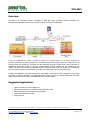
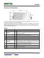
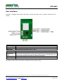
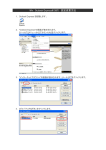
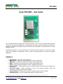
XTR-WiFi User Guide 650201320G Aurel XTR-WiFi - User Guide Aurel XTR-WiFi interface manages a Wi-Fi TCP/IP connection, with no need for complex stack operations by the user after an initial configuration. It automatically connects to a WiFi infrastructure (Access Point) with its own IP address, providing the native serial protocol (encapsulated in a TCP/IP packet) for remote application usage. XTR-WiFi incorporates in a single interface all the functions normally required for a CPU host: TCP/IP stack, Wi-Fi client/server configuration, DHCP or static IP address assignment, network MAC address assignment. Features WiFi Security - WEP, WPA, WPA2 supported; DHCP client - module’s IP set by DHCP server or static configuration; DNS client - IP address retrieving from symbolic name by DNS server; PING - Connectivity test towards other network nodes (ICMP protocol); SCAN - Specific command provided to scan for available Access Points; Smart ConfigTM - Texas Instruments tool to configure modules via smart devices avoiding user commands; TCP Server Mode - Default configuration to listen for incoming connection, UART local notifications, transparent data transfer modality; TCP Client Mode - Remote server connection, transparent data transfer modality; mDNS Advertiser - Periodic multicast DNS packet for specific browsers. Technical features are subject to change without notice. AUREL S.p.A. does not assume responsibilities for any damages caused by the device’s misuse. AUREL S.p.A. Via Foro dei Tigli, 4 - 47015 Modigliana (FC) – ITALY Tel.: +39.0546.941124 Fax: +39.0546.941660 http://www.aurelwireless.com - email: [email protected] LT - Rev.C - 08/05/2014 pag. 1 of 21 XTR-WiFi User Guide 650201320G Overview XTR-WiFi is an integrated module, complaint to IEEE 802.11b/g, supporting WLAN connection for infrastuctured networks based on IPv4 TCP/IP protocol. A sample PC application It can be configured as a client, in order to connect to a remote server, or as server, listening for incoming connection. At startup module is in command mode and through a simple AT command set the customer host can configure it and start the data exchange entering in data mode. Once connection is established, serial data (UART or SPI) are encapsulated in TCP/IP packets and are available for the remote host that can use them at application level, extracting them from TCP packets in a transparent way. An escape sequence is provided to close data connection and return to command mode. A sample PC application has been developed in Visual Basic 2010 Express (.NET Framework 4.0) in order to provide a reference example for remote applications (client or server) to exchange data with XTR-WiFi. Whole project and source code are available for users and developers. Suggested Applications WiFi connectivity for home appliances M2M communications for industrial monitoring and control Patient monitoring and medical instrumentation Home and building automation Energy Control Technical features are subject to change without notice. AUREL S.p.A. does not assume responsibilities for any damages caused by the device’s misuse. AUREL S.p.A. Via Foro dei Tigli, 4 - 47015 Modigliana (FC) – ITALY Tel.: +39.0546.941124 Fax: +39.0546.941660 http://www.aurelwireless.com - email: [email protected] LT - Rev.C - 08/05/2014 pag. 2 of 21 XTR-WiFi User Guide 650201320G Mechanical Characteristics XTR-WiFi is accessible by a 2mm-pitch strip. Strip can be provided straight or in 90° version, in order to meet mechanical requirements of the final application. By default an integrated PIFA antenna is embedded in the module. If necessary, a UFL connector equipped module can be provided (it results in a different size), in order to use an external antenna. This solution should be used when the module is enclosed in a metallic case or whenever radio conditions do not allow an acceptable budget link. Pinout Pin 1 Name GND 2 SPI-IRQ 3 SPI-MOSI/UART-TX 4 5 6 7 SPI-CLK GND Button 1 GPIO 8 UART/SPI* 9 SPI-MISO/UART-RX 10 SPI-CS 11 RST 12 VCC Function IN Ground Used in SPI mode (active high) to indicate data ready from XTROUT WiFi. If SPI is used add a pull-down to this net in order to avoid IRQ spurious activation. Tx output from XTR-WiFi if used by UART, I/O SPI-MOSI input for XTR-WiFi if used by SPI. IN SPI clock. IN Ground IN Active low, internal pull-up. SmartConfigTM procedure start signal. Unused Selection between UART (logic level high) and SPI (logic level low) user serial interface. Value is read at startup, to switch interface real IN time XTR-WiFi should be reset. Pin is equipped with an internal pullup to use module in UART mode by default. Rx input for XTR-WiFi if used by UART, I/O SPI-MOSI output for XTR-WiFi if used by SPI. IN SPI Chip Select. XTR-WiFi reset, active low, with internal pull-up. IN Connected to RST Button. IN Power supply (3.3V typical). Technical features are subject to change without notice. AUREL S.p.A. does not assume responsibilities for any damages caused by the device’s misuse. AUREL S.p.A. Via Foro dei Tigli, 4 - 47015 Modigliana (FC) – ITALY Tel.: +39.0546.941124 Fax: +39.0546.941660 http://www.aurelwireless.com - email: [email protected] LT - Rev.C - 08/05/2014 pag. 3 of 21 XTR-WiFi User Guide 650201320G Electrical Characteristics Power Supply Current Consumption Frequency RMS Output Power Temperature range Min 2.7 280 112 210 112 2.401 Typical 3.3 Max 3.6 295 123 227 123 2.483 17 -20 70 Unit VDC mA mA mA mA GHz dBm °C Note 802.11b - Tx 802.11b - Rx 802.11g - Tx 802.11g - Rx IEEE STD 802.11b(1) NOTE 1: Standard 20MHz channel bandwidth Device usage In order to obtain performances described in the technical specifications and to comply with operating conditions which characterize the Certification, the device must be mounted on a printed circuit taking into account the following: Voltage Supply 1. Module must be powered by a low voltage safety source, protected against short circuits. Maximum allowed voltage variations is 2.7 ÷ 3.6V. 2. Provide voltage decoupling near the transmitter with a ceramic capacitor of at least 100 nF. Ground Ground must surround in the best possible way the transceiver welding area. The ground plane should be on the lower side and there must be no integrated circuits near the antenna in order to avoid coupling. Other components 1. Keep the device away at least 5mm from all other components on the circuit 2. Keep microprocessors and their clock circuits particularly far away and shielded. Reference Standards The XTR-WiFi modules comply with the European standards EN 300-228 and EN 301-489 with maximum power supply of 3.6V. The product has been tested according to EN 60950 and can be used inside a special housing that ensures compliance with the above mentioned regulations. The device must be powered by a low voltage safety source protected against short circuits. The use of the module is foreseen inside housings that assure the overcoming of standards EN 61000 not directly applicable to the module itself. In particular, it is the user's care isolation antenna as the RF output of the transmitter is not able to support directly the electrostatic charges foreseen by the standard EN 61000-4-2. Technical features are subject to change without notice. AUREL S.p.A. does not assume responsibilities for any damages caused by the device’s misuse. AUREL S.p.A. Via Foro dei Tigli, 4 - 47015 Modigliana (FC) – ITALY Tel.: +39.0546.941124 Fax: +39.0546.941660 http://www.aurelwireless.com - email: [email protected] LT - Rev.C - 08/05/2014 pag. 4 of 21 XTR-WiFi User Guide 650201320G User interfaces XTR-WiFi is equipped with buttons and LEDs on board that allow users to directly interact with the module. Button SmartConfigTM Button 2 Button RST Function SmartConfigTM procedure manual start (connected to pin 6 ‘Button 1’). unused XTR-WiFi reset (connected to pin 11 ‘RST’). LED Function Blink during SmartConfigTM procedure and switch on when it’s complete. Turn off when XTR-WiFi enters in data mode (module ready to exchange data with a remote node) and blink when data are effectively exchanged. Infrastructure ready: switched on at XTR-WiFi connected to an Access Point. Communication estabilished: switched on when XTR-WiFi has acquired an IP address. TM SmartConfig Data / Infrastructure Communication At startup all LEDs make a check blink to indicate that the module is ready. Technical features are subject to change without notice. AUREL S.p.A. does not assume responsibilities for any damages caused by the device’s misuse. AUREL S.p.A. Via Foro dei Tigli, 4 - 47015 Modigliana (FC) – ITALY Tel.: +39.0546.941124 Fax: +39.0546.941660 http://www.aurelwireless.com - email: [email protected] LT - Rev.C - 08/05/2014 pag. 5 of 21 XTR-WiFi User Guide 650201320G Serial interfaces For user data transmit XTR-WiFi is equipped with both UART and SPI serial interfaces. The choice between the two is done by a dedicated pin (UART/SPI*). If logical level is high (or, due to the internal pull-up, pin is unconnected) UART is used, if logical level is low SPI is activated. UART/SPI* value is read at startup, so it is necessary to reset the module after a switch from using a serial interface to the other one. UART settings Baud rate Data bits Parity Stop bits Flow control 19200 bps 8 None 1 None TTL levels for UART lines are required. SPI features In SPI mode XTR-WiFi act as a slave. Both cases with data available from master or form slave are explained. Data available from XTR-WiFi (Slave). XTR-WiFi raises SPI-IRQ line (pin 2). Master should activate SPI interface (signals SPI-CLK, pin 4, and SPI-CS, pin 10) and read all data from SPI-MISO line (pin 9, in this case output for XTR-WiFi) until SPI-IRQ is lowered. SPIIRQ is lowered at the beginning of the second-last byte transmission, so pay attention to read the whole available packet. In this phase SPI-MOSI line is ignored. In order to avoid spurious activation of SPI-IRQ signal, a pull-down resistor is recommended on this pin. Note that XTR-WiFi gets stuck until all available data from master are properly read. Data available from Master. Master can write directly to the XTR-WiFi using SPI interface: driving properly SPI-CLK (pin 4), SPI-CS (pin 10) and SPI-MOSI (pin 3, in this case input for the XTR-WiFi) lines. In this case SPI-MISO line is ignored. In both cases data are supposed to be stable and should be sampled on the rising edge of SPI-CLK. The most significant bit of any byte is transmitted first. Technical features are subject to change without notice. AUREL S.p.A. does not assume responsibilities for any damages caused by the device’s misuse. AUREL S.p.A. Via Foro dei Tigli, 4 - 47015 Modigliana (FC) – ITALY Tel.: +39.0546.941124 Fax: +39.0546.941660 http://www.aurelwireless.com - email: [email protected] LT - Rev.C - 08/05/2014 pag. 6 of 21 XTR-WiFi User Guide 650201320G TCP/IP basic concepts Two logical steps are necessary to have a working device on a WiFi network: 1. Connection to the physical infrastructure: device should be recognized by the infrastructure manager, an Access Point in the case of WiFi, that sort data packets from each node of the network to the others through the physical transmission medium available (a 2.4GHz radio channel). 2. Acquisition of communication parameters: once the device is able to physically exchange data with other nodes in the network, it’s necessary that it be identifiable by an address, in order to be reached from the other nodes of the same network. Identification parameters depends by the network protocol, in this case Internet Protocol is used, so each node is identified by an unique IP address. Communication between two nodes of a WiFi network is done at the same way as computer networks, and is based on the client - server model. This is a structure in computing that partitions tasks between the provider of a resource, called server, and service requesters, called clients. A TCP server serve one or more clients establishing a TCP connection between itself and the clients. For each side there is an endpoint of the communication flow that is called network socket. A server creates sockets that are in listening state, waiting for initiatives from client programs. Each socket is characterized by a unique combination of an IP address and a TCP port number. For each connection an unique dedicated socket is created but a server could also create several concurrently TCP sockets, it depends by available computing resources. TCP protocol is connection oriented and Internet socket usage is usually based on the Berkeley sockets standard. It assumes that servers are in listen state, ready to accept incoming connections. A client make a request to the server to establish a connection, specifying address and port number of the server itself. Server accepts the connection and authorizes client to send data; at this time client and server are connected and can transfer data each other. If there are no more data to transmit the client call to release the connection, the server accept, and both client and server can free resources for reuse in further connections. It’s much important to release resources in a connection-oriented protocol so, in order to prevent failures on receiving release requests (i.e. if the transmission channel fall), usually a timeout (for each side) unilaterally close the communication after a given time from the last data exchanged. Technical features are subject to change without notice. AUREL S.p.A. does not assume responsibilities for any damages caused by the device’s misuse. AUREL S.p.A. Via Foro dei Tigli, 4 - 47015 Modigliana (FC) – ITALY Tel.: +39.0546.941124 Fax: +39.0546.941660 http://www.aurelwireless.com - email: [email protected] LT - Rev.C - 08/05/2014 pag. 7 of 21 XTR-WiFi User Guide 650201320G AT Commands At start-up a welcome string is reported to customer host1: It indicates the firmware version currently loaded on the module (0.3-1.24 in this case) and that XTR-WiFi is on and ready to accept commands. In fact, at startup XTR-WiFi is in command mode, so can accept commands trough serial interface (the command set is the same using either UART or SPI interface). Any command is parsed and interpreted by XTR-WiFi when a carriage return (0x13) is detected at the end of the string. When a command is sent to module without carriage return at the end, string is processed anyway after about 3 milliseconds from last received character. If a command is unrecognized an appropriate message is returned. Basics +++ (Escape Sequence) To return to command mode after a data transfer it is necessary to send a “+++” sequence at the beginning of a new data packet. XTR-WiFi indicate the switch of modality and implicitly that previous active connection has been closed. Pay attention to avoid the “+++” sequence while exchanging application data because it involves at any time a connection closing. AT Sending a simple AT command (with no arguments) XTR-WiFi answers just to check UART communication. 1 For each example RealTerm serial terminal has been used [http://realterm.sourceforge.net/] Technical features are subject to change without notice. AUREL S.p.A. does not assume responsibilities for any damages caused by the device’s misuse. AUREL S.p.A. Via Foro dei Tigli, 4 - 47015 Modigliana (FC) – ITALY Tel.: +39.0546.941124 Fax: +39.0546.941660 http://www.aurelwireless.com - email: [email protected] LT - Rev.C - 08/05/2014 pag. 8 of 21 XTR-WiFi User Guide 650201320G Communication Communication parameters are hierarchically more important than connection ones, though they regards only the second stage of the network join. For this reason user must set communication parameters first than connection parameters, because when the Access Point accept the module to join the network, affiliation modality need to be already configured (the concept is valid also if DHCP is used). AT+CONF=[IP_Address];[NetMask];[Gateway];<DNS_Server> This command set statically IP parameters for Wi-Fi network identification and location addressing: Module IP Address, NetMask, Gateway and DNS server (each ‘;’ is needed, <DNS_Server> parameter is optional). IP_Address: Internet Protocol (local) network address of the device. NetMask: bitmask that separate network identifier (‘192.168.0’ in the example) from host identifier (‘3’ in the example), used to discriminate if the message destination is a node of the local network or it must be externally reached through the gateway. Gateway: IP address of the device to which forward messages that are destinated out from the local network, as the result of the net mask process. DNS_Server (optional): IP address (usually external to the local network) of the server that translates domain names to numerical IP addresses, needed for the purpose to locating services and devices worldwide. AT+CONF command force the disconnection from current network in order to perform requested operation. If the module was connected to an Access Point before receiving the command, it tries to reconnect to the same, but using new settings. Be careful not to create conflicts allocating static IP Addresses (i.e. the same Address to multiple nodes), it can compromise network functionalities. IP settings are also stored in non-volatile memory to be preserved after a reboot. Technical features are subject to change without notice. AUREL S.p.A. does not assume responsibilities for any damages caused by the device’s misuse. AUREL S.p.A. Via Foro dei Tigli, 4 - 47015 Modigliana (FC) – ITALY Tel.: +39.0546.941124 Fax: +39.0546.941660 http://www.aurelwireless.com - email: [email protected] LT - Rev.C - 08/05/2014 pag. 9 of 21 XTR-WiFi User Guide 650201320G AT+DHCP Instruct node to retrieve IP configuration from a DHCP server. DHCP is the default IP assignment mode for XTR-WiFi. If the module was connected to an Access Point AT+DHCP command force disconnection from current network in order to perform the requested operation. If DHCP mode is chosen but no DHCP server is provided, XTR-WiFi can get stuck waiting for IP address assignment, pay attention to avoid this condition. Infrastructure connection AT+SCAN With this command is possible to force XTR-WiFi to perform a scan for available WiFi networks in the area. For each network SSID, RSSI value and security encryption type are reported. In case of no network is detected an appropriate message is produced. Pay attention that all desired SSID name are visible, some Access Points can hide it in their settings. Furthermore some N network mode Access Points sets by default channel bandwidth at 40MHz (wide mode), it’s recommended to choose standard 20MHz channel bandwidth. Technical features are subject to change without notice. AUREL S.p.A. does not assume responsibilities for any damages caused by the device’s misuse. AUREL S.p.A. Via Foro dei Tigli, 4 - 47015 Modigliana (FC) – ITALY Tel.: +39.0546.941124 Fax: +39.0546.941660 http://www.aurelwireless.com - email: [email protected] LT - Rev.C - 08/05/2014 pag. 10 of 21 XTR-WiFi User Guide 650201320G AT+CONN=[SecurityLevel];[Ssid];<SecurityKey> With this command is possible to instruct XTR-WiFi to connect to an Access Point specifying its infrastructure parameters (each ‘;’ is needed, <SecurityKey> is optional). SecurityLevel: UNSEC WEP WPA WPA2 - no security (open access point): no encryption Wired Equivalent Privacy: 64bit key encryption Wi-Fi Protected Access: dynamic 128bit key encryption Wi-Fi Protected Access II: 256bit key encryption SSID: Service Set IDentifier, commonly called the “network name”. SecurityKey: omitted for unsecured connections, for WEP connections key should be composed only of ASCII characters. When the connection is established an apposite message is given from XTR-WiFi. Than the module start network join negotiation, obtaining an IP address from the Access Point according to the previous defined modality (static or DHCP assigned). When XTR-WiFi is connected to an Access Point it automatically issue a TCP server listening on last used port (default port 4444 if not previously chosen a different one). With further commands is possible to make it work as a client or a server listening on a different user-defined port. At the following startup XTR-WiFi will try to connect automatically to the same Access Point, remembering last connection parameters. If XTR-WiFi is connected to an infrastructure that goes down a message is reported. Technical features are subject to change without notice. AUREL S.p.A. does not assume responsibilities for any damages caused by the device’s misuse. AUREL S.p.A. Via Foro dei Tigli, 4 - 47015 Modigliana (FC) – ITALY Tel.: +39.0546.941124 Fax: +39.0546.941660 http://www.aurelwireless.com - email: [email protected] LT - Rev.C - 08/05/2014 pag. 11 of 21 XTR-WiFi User Guide 650201320G AT+SMRT XTR-WiFi is compliant with SmartConfigTM tool2 by Texas Instruments, that is a one-time process to connect an embedded Wi-Fi device to a wireless network. It allows to configure a module using a smartphone, a tablet or a PC, with no need for most complex operations from customer host. In details the application allows the user to connect XTR-WiFi to an existing Access Point passing to it the infrastructure parameters directly from a smart device, by-passing the AT+CONN serial command. The smart device must be connected to the same Access Point via WiFi, so SmartConfigTM application3 running on it can grab infrastructure parameters and transfer them to the module, previously initialized to accept data. SmartConfigTM App than show on the screen a confirm message in case of success. Procedure: 1. Connect a smart device to the desired WiFi network. 2. Send a AT+SMRT command to XTR-WiFi (or push SmartConfigTM Button, or drive low BUTTON 1 pin). A message is produced to indicate that command has been received and procedure has begun. 3. Launch SmartConfigTM application in the smart device and configure it: SSID is automatically grabbed from the active Wi-Fi connection; if encryption is used, type the network key in Password field; Gateway IP Address is automatically grabbed from the active Wi-Fi connection; Key checkbox must be unchecked; Device Name has to match the default mDNS name given by the module at the end of SmartConfigTM procedure: type “AurelWiFi”. 4. press Start button. 2 http://processors.wiki.ti.com/index.php/CC3000_Smart_Config 3 SmartConfigTM for iOS, Android and PC can be downloaded from http://www.ti.com/tool/smartconfig Technical features are subject to change without notice. AUREL S.p.A. does not assume responsibilities for any damages caused by the device’s misuse. AUREL S.p.A. Via Foro dei Tigli, 4 - 47015 Modigliana (FC) – ITALY Tel.: +39.0546.941124 Fax: +39.0546.941660 http://www.aurelwireless.com - email: [email protected] LT - Rev.C - 08/05/2014 pag. 12 of 21 XTR-WiFi User Guide 650201320G After few seconds, if procedure complete successfully, the module is connected to the Access Point and automatically issue a TCP server listening on last used port (default port 4444 if not previously chosen a different one). Subsequently with further commands is possible to make it work as a client or as a server listening on a different user-defined port. During SmartConfigTM procedure no command can be received, it does not have an expiration time-out, so to break it it’s necessary to reset the module (pin 11 ‘RST’, or Button RST) or turn it off. If the module was previously connected to an Access Point, during the SmartConfigTM procedure some error messages can occur (due to the fact that in background it try to join with the known AP) but normally it does not affect the successfully procedure ending, signaled reported messages. Note: pay attention using DHCP or static IP functionality according to network capabilities, also if SmartConfigTM is used. During SmartConfigTM procedure the security key is passed unencrypted from smart device to XTR-WiFi module. At the following startup XTR-WiFi will try to connect automatically to the same Access Point, remembering last connection parameters. Technical features are subject to change without notice. AUREL S.p.A. does not assume responsibilities for any damages caused by the device’s misuse. AUREL S.p.A. Via Foro dei Tigli, 4 - 47015 Modigliana (FC) – ITALY Tel.: +39.0546.941124 Fax: +39.0546.941660 http://www.aurelwireless.com - email: [email protected] LT - Rev.C - 08/05/2014 pag. 13 of 21 XTR-WiFi User Guide 650201320G AT+DSCN XTR-WiFi disconnects from the current Access Point. In case it was already disconnected an apposite message is produced. Diagnostic AT+IPC Interrogate XTR-WiFi to read all current Wi-Fi connection parameters (module IP Address, Gateway, current SSID and MAC address). Informations are correctly retrieved if the module is connected to an Access Point, otherwise various ‘0’ fields are reported. In this case SSID reported is the last used by the module. Technical features are subject to change without notice. AUREL S.p.A. does not assume responsibilities for any damages caused by the device’s misuse. AUREL S.p.A. Via Foro dei Tigli, 4 - 47015 Modigliana (FC) – ITALY Tel.: +39.0546.941124 Fax: +39.0546.941660 http://www.aurelwireless.com - email: [email protected] LT - Rev.C - 08/05/2014 pag. 14 of 21 XTR-WiFi User Guide 650201320G AT+PING=[IP Address] Ping (ICMP protocol) a remote host to test network connectivity. Four 56-byte packets are sent to the remote host and afterwards a report is produced. In case a DNS server is available, it’s possible to specify a symbolic name instead of the explicit IP address. DNS server’s IP is the last parameter given in a manual specified configuration (command AT+CONF), otherwise is automatically returned by the Access Point at the connection if DHCP modality is choosen. A local DSN server resolve symbolic name replacing it with the correspondent device IP address. If XTR-WiFi has access to the Internet, a public DNS server (like OpenDNS, 208.67.222.222) resolve also IP addresses of domain name resources. If DNS server is not properly configured, or is not available, a specific error code is returned. Technical features are subject to change without notice. AUREL S.p.A. does not assume responsibilities for any damages caused by the device’s misuse. AUREL S.p.A. Via Foro dei Tigli, 4 - 47015 Modigliana (FC) – ITALY Tel.: +39.0546.941124 Fax: +39.0546.941660 http://www.aurelwireless.com - email: [email protected] LT - Rev.C - 08/05/2014 pag. 15 of 21 XTR-WiFi User Guide 650201320G AT+MDNS=MyDevice mDNS (multicast DSN4) is a host name resolution service that uses same semantics as DNS within networks that do not include a local name server. AT+MDNS command set a custom name for XTR-WiFi and broadcast a relative mDNS packet on the network so, as happens for DNS, is possible to associate a specified symbolic name to the IP address. mDNS protocol is implemented by Apple Bonjour and Linux nss-mdns services and informations can be retrieved using apposite mDNS browsers, for example: ‘Discovery’ or ‘mDNS Watch’ for iOS and ‘Bonjour Browser’ or ‘ZeroConf Browser’ (both exampled) for Android. Anyway, if the module is connected to an Access Point, about every 10 seconds an ‘AurelWiFi’ default mDNS message is automatically broadcasted through the network, to inform remote nodes about the presence of an XTR-WiFi module. If the module is not connected to an Access Point is not possible to send mDNS informations and an apposite message is returned. At the end of the SmartConfigTM procedure is precisely a mDNS packet with the default name ‘AurelWiFi’ that notify to the App that procedure has been successfully completed. 4 http://en.wikipedia.org/wiki/Multicast_DNS Technical features are subject to change without notice. AUREL S.p.A. does not assume responsibilities for any damages caused by the device’s misuse. AUREL S.p.A. Via Foro dei Tigli, 4 - 47015 Modigliana (FC) – ITALY Tel.: +39.0546.941124 Fax: +39.0546.941660 http://www.aurelwireless.com - email: [email protected] LT - Rev.C - 08/05/2014 pag. 16 of 21 XTR-WiFi User Guide 650201320G Data transmission AT+CLNT=[IP Address];[Port Number] Connect XTR-WiFi as a client to a remote socket indicated by server IP address and port number. If connection is successful XTR-WiFi passes to data mode, otherwise an error message is reported. Errors are reported within 60 seconds form the connection attempt. Pay attention that remote server is not protected by a firewall to avoid systematic connection failures. Similarly to AT+PING command, if a DNS server is correctly configured it is possible to specify a symbolic name instead of the explicit IP address. DNS server resolve symbolic name replacing it with the correspondent device IP address and show it. If XTR-WiFi is in data mode up to 61 byte at a time are sent to remote node, no special characters are used apart the “+++” sequence that switch to command mode, pay attention to avoid this sequence while exchange application data. After about 60 seconds from the last transmitted data, connection automatically shut down to free resources and the module return to command mode. If remote server is a XTR-WiFi it also automatically shut down the connection after 50 seconds from last transmitted data, the connected client node can detect this trying to send data, and then returning a message error. When XTR-WiFi returns to command mode, by default automatically issue a TCP server listening on last used port as server (default port 4444 if not previously chosen a different one). Technical features are subject to change without notice. AUREL S.p.A. does not assume responsibilities for any damages caused by the device’s misuse. AUREL S.p.A. Via Foro dei Tigli, 4 - 47015 Modigliana (FC) – ITALY Tel.: +39.0546.941124 Fax: +39.0546.941660 http://www.aurelwireless.com - email: [email protected] LT - Rev.C - 08/05/2014 pag. 17 of 21 XTR-WiFi User Guide 650201320G AT+SRVR=[Port Number] Issue a TCP server on a specified port, than XTR-WiFi starts listening for a client connection request. When an incoming connection is received the module returns the IP address of the requesting client node and then switch to data mode. Data received from remote nodes are redirected to serial interface in transparent mode and become available for customer host. To return to command mode (thus closing active connection) it is necessary to send a “+++” sequence at the beginning of a new data packet: pay attention to avoid this sequence while exchange application data. Returning in command mode, or also connecting the module to another Access Point, XTR-WiFi issue by default a server listening on last used port (default port 4444 if not previously chosen a different one). Therefore, after about 50 seconds from last transmitted data connection automatically shut down (to free resources) and the module returns to command mode. To start a server on a different port is first necessary to stop the current issued server (AT+STOP command) ad then start a new one. At startup port number returns the default 4444. Technical features are subject to change without notice. AUREL S.p.A. does not assume responsibilities for any damages caused by the device’s misuse. AUREL S.p.A. Via Foro dei Tigli, 4 - 47015 Modigliana (FC) – ITALY Tel.: +39.0546.941124 Fax: +39.0546.941660 http://www.aurelwireless.com - email: [email protected] LT - Rev.C - 08/05/2014 pag. 18 of 21 XTR-WiFi User Guide 650201320G AT+STOP Stop server listening. If a connection from a client was estabilished the module is in data mode, so it’s necessary to send a “+++” sequence before. If no server is currently running an apposite message is returned. Technical features are subject to change without notice. AUREL S.p.A. does not assume responsibilities for any damages caused by the device’s misuse. AUREL S.p.A. Via Foro dei Tigli, 4 - 47015 Modigliana (FC) – ITALY Tel.: +39.0546.941124 Fax: +39.0546.941660 http://www.aurelwireless.com - email: [email protected] LT - Rev.C - 08/05/2014 pag. 19 of 21 XTR-WiFi User Guide 650201320G Quick start A simple sequence of commands is suggested for a first approach to the module. Apart from basic and diagnostic commands, for the core functionality there are 2 ways to do the same things: a ‘professional’ one, in which user must know WiFi parameters to configure the connection, and a ‘smart’ one, in which some kind of automatic configuration does the job instead of the user. AT check UART communication AT+SCAN check if desired WiFi network is available in the area PRO approach AT+CONF SMART approach set manually IP parameters AT+DHCP (default setting) retrieve IP configuration automatically from the AP AT+CONN connect module to a specified Access Point AT+SMRT connect module through SmartConfigTM procedure AT+SRVR AT+CLNT use module as a server connect module as a client Error Table If a command return an error it is followed by an exit value with its explicit meaning: Error Code Error 1 Error 2 Error 3 Error 4 Error 5 Error 6 Error 7 Error 8 Error 9 Error 10 Error 11 Error 12 Description Syntax Error Error in connection to the Access Point Error opening TCP socket Error binding TCP socket Error while listening for incoming connections Error sending data Error closing socket Invalid number of arguments Error connecting to remote server Error during mDNS Error interrogating DNS server, while resolving a symbolic name Error while executing ping request Technical features are subject to change without notice. AUREL S.p.A. does not assume responsibilities for any damages caused by the device’s misuse. AUREL S.p.A. Via Foro dei Tigli, 4 - 47015 Modigliana (FC) – ITALY Tel.: +39.0546.941124 Fax: +39.0546.941660 http://www.aurelwireless.com - email: [email protected] LT - Rev.C - 08/05/2014 pag. 20 of 21 XTR-WiFi User Guide 650201320G Aurel TCP Terminal In order to support developers, a sample application is provided 5. It has been developed in Visual Basic 2010 Express6 (.NET Framework 4.0) and whole project and source code are available for users. It implements a simple TCP socket which can be used as a client or as a server, and allow to set connection parameters. Server mode IP Address: given by PC port number: should be specified. Listen start server listening. Remote client request acceptance is notified in the status bar. Send Message send data to remote node Close Connection close the socket Client mode IP Address: should be specified Port number: should be specified Connect to Server let application try to connect to specified remote server. A successful connection is notified in the status bar. Send Message send data to remote node Close Connection close the socket When connection is established it is possible to send ascii characters to remote node (e.g. XTR-WiFi) and view received data in the large textbox. PC firewalls can block TCP Terminal’s socket communication, be sure to unblock it. 5 Project and source code files are downloadable from http://www.aurelwireless.com/en/wireless-news/wi-fi-interface-rf-module/, the executabile file is “AUREL_TCP_Terminal/0.2/bin/Debug/AUREL_TCP_Terminal.exe” 6 http://www.visualstudio.com/downloads/download-visual-studio-vs Technical features are subject to change without notice. AUREL S.p.A. does not assume responsibilities for any damages caused by the device’s misuse. AUREL S.p.A. Via Foro dei Tigli, 4 - 47015 Modigliana (FC) – ITALY Tel.: +39.0546.941124 Fax: +39.0546.941660 http://www.aurelwireless.com - email: [email protected] LT - Rev.C - 08/05/2014 pag. 21 of 21