1
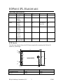
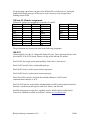
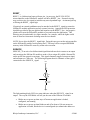
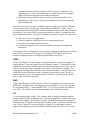
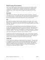
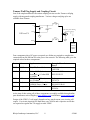
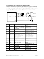
IOPoint-PL User’s Manual
2006-03-31A
© 2006 Bibaja Landscape Automation, LLC
INTRODUCTION
1
12 CONFIGURABLE I/O PINS
3 NETWORK ACTIVITY INDICATOR OUTPUTS
DOCUMENT ORGANIZATION
1
1
1
IOPOINT-PL HARDWARE
2
OPERATING SPECIFICATIONS
PCB LAYOUT
IOPOINT-PL MODULE PINOUT
IO0-IO11
RESET_
SERVICE_
VDD5
GND
VA
RXIN (COUPLING CIRCUIT INTERFACE)
PKD (RX)
BIU
TXON (TX)
2
2
3
3
4
4
5
5
5
6
6
6
6
POWER SUPPLIES AND COUPLING CIRCUITS
7
IOPOINT-PL COUPLING COMPONENTS
RX COMPENSATION INDUCTOR (L3)
DC BLOCKING CAPACITOR (C7)
PROTECTION CLAMP DIODES (D3 AND D4)
TAMURA WALL PLUG SUPPLY AND COUPLING CIRCUIT
NON-ISOLATED 24 VOLT AC SUPPLY AND COUPLING CIRCUIT
Bibaja Landscape Automation, LLC
i
7
7
7
7
8
10
© 2006
INTRODUCTION
The IOPoint-PL is a programmable module with 12 I/O pins, 3 network activity indicator
pins, and embedded power line communications. With the addition of a simple coupling
circuit, power supply, and your I/O circuitry, you will have a complete, remotely
controllable device ideal for home, industrial, or building automation.
12 Configurable I/O Pins
Each IOPoint-PL module includes 12 configurable I/O pins. All of these pins are capable
of performing simple digital input and output functions. Other pins have timer/counter
functions useful for implementing a variety of input and output I/O models. For a
complete list of available pin functions, see the PL3120-E4T10 Smart Transceiver User’s
Guide available from Echelon’s website at www.echelon.com.
3 Network Activity Indicator Outputs
Transmit (TX), Receive (RX), and Band In Use (BIU) network activity indicator outputs
are included on the IOPoint-PL module. These outputs provide feedback for network
activity, when a particular IOPoint-PL responds to a message, and if there is noise on the
network that may impair performance. See the detailed pin descriptions in the IOPointPL Hardware section of this document.
Document Organization
This document is organized into three major sections:
1) Introduction –
This section you are reading now is meant to give an overview of the IOPointPL module features as well as explaining the different sections of the User’s
Manual.
2) IOPoint-PL Hardware Specifies the voltage and current ratings for the device. The PCB footprint is
given here (the same as in the datasheet). Detailed pin descriptions and
functions are listed. For complete pin descriptions of the 12 configurable I/O
pins, you will need to refer to the PL3120-E4T10 Smart Transceiver User’s
Guide on Echelon’s website at www.echelon.com.
3) Power Supplies and Coupling Circuits
This section presents a quick overview of how to build various power supplies
and coupling circuits for the IOPoint-PL module to get your signals on and off
the AC power mains. Users who are curious about learning how to design a
variant of these power supplies and coupling circuits should carefully read the
PL3120-E4T10 Smart Transceiver User’s Guide.
Bibaja Landscape Automation, LLC
1
©2006
IOPOINT-PL HARDWARE
Operating Specifications
Parameter
VA
VDD5
IDD5
IA(rx)
IA(tx)
Temp
Description
Analog
Supply
Digital
Supply
Voltage
Digital
Supply
Current
Analog
Supply
Current,
Receive
Analog
Supply
Current,
Receive
Operating
Temperature
Min
10.8
Typ
12
Max
18
Units
V
4.75
5.0
5.25
V
---
10
(depends on
your I/O)
ma
---
350
500
ua
---
120
250
ma
-20
25
85
C
PCB Layout
The following diagram shows the PCB layout required for mounting the IOPoint-PL
module in your design:
2.40
1.60
1.45
17
18
0.95
P1
Layout for IOPoint
Module Mounting
1.60
6
0.40
1
2
P2
0.15
1
0.10
0
0 0.15
Reference
3 Mounting Holes
P1, P2
Dimensions are in inches.
2.15 2.25
Pad O.D.
0.285
0.060
Bibaja Landscape Automation, LLC
Plated Hole Diameter
0.152
0.040
2
©2006
For prototyping convenience, the pins of the IOPoint-PL are laid out on a 0.1inch grid.
Standard perforated prototype PCBs may be used to mock up early designs before
building custom PCBs.
IOPoint-PL Module Assignments
IOPoint-PL Module pin assignments for headers P1 and P2:
Name
P1 Pin #
P1 Pin #
Name
IO8
17
18
SERVICE_
IO7
15
16
IO10
IO6
13
14
IO9
IO5
11
12
VDD5
RESET_
9
10
IO4
GND
7
8
IO3
GND
5
6
IO2
GND
3
4
IO1
IO11
1
2
IO0
Name
RXIN
VA
PKD
BIU
TXON
GND
P2 Pin #
6
5
4
3
2
1
The pin functions are described in detail in the following paragraphs.
IO0-IO11
IO0 through IO11 are the 12 configurable digital I/O pins. These pins map directly to the
pin on the PL3120-E4T10 Smart Transceiver chip on the IOPoint-PL module.
Pins IO0-IO3 have high current sink capability (20ma sink, 1.4ma source).
Pins IO4-IO7 and IO11 have configurable pull-ups.
Pins IO0-IO1 may be used as timer/counter output pins.
Pins IO4-IO7 may be used as timer/counter input pins.
Pins IO8 and IO10 may be used with the embedded hardware UART (serial
communications interface or SCI).
Pins IO7-IO10 may be used with the embedded hardware SPI (serial peripheral interface,
basically a synchronous shift register with clock, data in, and data out).
Detailed descriptions for each pin’s capability may be found in the Powerline Smart
Transceiver Databook available on Echelon’s website (www.echelon.com).
Bibaja Landscape Automation, LLC
3
©2006
RESET_
RESET_ is a bidirectional open-collector pin. At power up, the PL3120-E4T10
microcontroller on the IOPoint-PL module will drive RESET_ low. External circuitry
may use this active low signal to initialize any state dependant logic. An internal pull-up
will bring the RESET_ signal high.
If required, an external pushbutton may be attached to the RESET_ signal to restart the
IOPoint-PL module application and any external circuitry. Appropriate ESD protection
should be provided to prevent glitches and impulses on the RESET_ line. Any negative
glitches will cause the IOPoint-PL module to reset and restart the application. This
behavior may be undesirable in a light controller, for example, where the lights would
turn off from an electrostatic discharge near the reset button.
NOTE: Never drive the RESET_ signal high. Doing this may prevent the microcontroller
on the IOPoint-PL module from resetting itself. This may lead to corrupted EEPROM
memory in the IOPoint-PL caused by errant code execution.
SERVICE_
SERVICE_ is an active low bidirectional signal that indicates device status as an output
and can trigger the IOPoint-PL module to send a 6-byte unique ID (called a Neuron ID)
on the power line network as an input. This signal constantly toggles between an input
and an output at a 76Hz rate. The following diagram shows a schematic of the typical
connection to the SERVICE_ signal:
VDD5
R
LED
SERVICE_
Service
Button
The light emitting diode (LED) is a status indicator when the SERVICE_ signal is an
output. The way the LED blinks will tell you the state of the IOPoint-PL module:
•
•
Blinks once at power-up then stays off means an application is loaded,
configured, and running
Blinks once at power-up then blinks on and off at about a 1Hz rate means an
application is loaded, but the device is unconfigured (no subnet/node address or
Bibaja Landscape Automation, LLC
4
©2006
•
domain information has been programmed for the power line interface). The
application may or may not run depending on compile time options (a pragma
which will make the application run when unconfigured.)
Blinks once at power-up then turns on and stays on means the IOPoint-PL is
applicationless. The device is waiting for an application to be loaded from the
power line network.
When the service pin is an input, it will detect the state of the service button. When the
service button is pressed, a low level will be read on the SERVICE_ input. This low
level input will cause the IOPoint-PL module to transmit a unique 6-byte ID on the power
line network. This 6-byte ID is how the network interface is able to communicate with
and configure new devices. The typical installation scenario for a power line network is:
1)
2)
3)
4)
Wire up new device and apply power
Prepare computer to install new device by entering install mode
Press the service button on the new device
Confirm the computer has received the unique ID message and complete the
installation.
The computer will be running some sort of network management application to configure
new devices on the network. Echelon offers LonMaker for Windows and the LNS
Network Operating System for configuring and installing new devices.
VDD5
VDD5 is the digital 5 volt power input. An external regulator is required to produce a
clean noise free 5-volt power supply for the IOPoint-PL module. If you intend to use the
IOPoint-PL in a system with other digital logic that may produce a lot of noise, you may
wish to consider providing an isolated 5-volt supply for the IOPoint-PL module. Too
much digital switching noise will reduce your receive performance by about 12dB. This
could easily be the difference between a working or non-working system. Be sure to
always check your receive attenuation tolerance carefully as per the Smart Transceiver
User’s Guide verification checklist.
GND
GND is the IOPoint-PL module ground. A total of 4 ground pins are provided on the
IOPoint-PL. In addition, the 3 mounting points for the module are also tied to ground.
We recommend using ½” metal standoffs and ¼” #6-32 screws to mount the module to
your PCB. This will provide good solid grounding for the IOPoint-PL module.
VA
VA is the analog supply voltage. This voltage is used to supply the transmit amplifier
and the transmit voltage monitoring circuit. If power management is enabled (for energy
storage power supplies), the IOPoint-PL module will stop any transmission in progress
and wait for the VA supply to recharge up to around 12 volts. An external capacitor of at
least 120uF (1500uF for a wall-plug supply) is required. See the chapter on power
supplies and coupling circuits for more details and the Smart Transceiver User’s Guide.
Bibaja Landscape Automation, LLC
5
©2006
RXIN (Coupling Circuit Interface)
RXIN is the TX/RX signal path between the power line transceiver and the coupling
circuit. Part of the coupling circuit is integrated on the IOPoint-PL module for your
convenience. You must provide the remainder of the circuit on your application
electronics PCB. See the chapter on power supplies and coupling circuits for more
details.
PKD (RX)
PKD (packet detect) indicates when a packet receive (RX) is in progress. This pin is
active high, driven to 5 volts, and may be used to drive an LED for monitoring activity on
the power line network. No pulse stretching is required since the majority of packets on
the power line network are in the 40ms range and are easily seen on the LED.
BIU
BIU (band in use) indicates a tone is present on the power line network. BIU is active
high, driven to 5 volts when a tone is present on the power line network above a certain
threshold. This signal may be used to drive an LED for monitoring signals present on the
power line network.
In Europe, BIU is used to share the power line between different power line carrier
devices. For the European sharing feature to work, the CENELEC access protocol must
be enabled by configuring the transceiver parameters to be PL-20C. By default, the
IOPoint-PL module ships with PL-20N parameters (N stands for no protocol, C stands for
CENELEC protocol.) The transceiver parameters may be changed using the NodeLoad
application available from the downloads section of Echelon’s website.
In addition to the power line sharing function, BIU is also a useful indicator of in-band
noise on the power line. The LED will blink when in-band noise is present. High levels
of noise may prevent proper communications on the power line network. Filtering on
noisy devices may sometimes be required for reliable communications.
TXON (TX)
TXON, transmitter on, indicates a packet transmit (TX) is in progress. This active high
5-volt signal may be used to drive an LED for monitoring network activity. Each time
the SERVICE_ signal is driven low, there will be one pulse on the TXON signal to
indicate the unique ID message was transmitted. When combined with the PKD (RX)
indicator, the TXON (TX) indicator will help you to clearly see communications
occurring with a particular IOPoint-PL module.
Bibaja Landscape Automation, LLC
6
©2006
POWER SUPPLIES AND COUPLING
CIRCUITS
Proper design of power supplies and coupling circuits for use with the IOPoint-PL
module are critical for achieving full communications performance. We recommend
thoroughly reading the PL 3120/ PL 3150 Power Line Smart Transceiver Data Book from
Echelon (www.echelon.com) for full details. Chapter 5 discusses power supply selection
in great detail, and chapter 4 talks about different coupling circuits. These sections are a
MUST READ if you are to succeed in designing a reliable power line communications
device.
This chapter presents a brief overview of what coupling components are already included
on the IOPoint-PL module. Two example power supply/coupling circuit combinations
are presented to show how you may use the IOPoint-PL in your system.
IOPoint-PL Coupling Components
There are 4 coupling components included on each IOPoint-PL module. These coupling
components correspond to L3, D1, D2, and C2 in Echelon’s PL 3120/PL 3150 Power
Line Smart Transceiver Data Book.
RX Compensation Inductor (L3)
For the receive circuitry, the RX compensation inductor (L3 in Echelon’s data book) is
provided. Make certain no other inductors are placed near this inductor. If two inductors
are laid in parallel, the signal from one may couple into the other. If your design requires
another inductor to be placed close to IOPoint-PL inductor L3, then make certain your
inductor is oriented orthogonally to L3 to minimize coupling. Coupling from power
supply inductors may impair receive performance and may inject noise back on to the
power line causing conducted emissions violating FCC and CENELEC regulations.
DC Blocking Capacitor (C7)
A DC blocking capacitor is provided on each IOPoint-PL module. This capacitor
corresponds to C2 in Echelon’s data book. The transmitter circuit is biased at about ½ of
the VA supply. This capacitor prevents shorting the transmitter bias voltage to the
potential of the remainder of the coupling circuit.
Protection Clamp Diodes (D3 and D4)
Protection clamp diodes D3 and D4 are included to protect the transmit and receive
circuits from large impulses that may get through the power supply and coupling
circuitry. The power supply should provide adequate protection in the form of a varistor,
transient voltage suppressor, or gas discharge tube. These clamp diodes act as the last
line of defense and are design to react very quickly to short transients on the line that may
get past slower protection circuits. These diodes correspond to D1 and D2 in Echelon’s
data book.
Bibaja Landscape Automation, LLC
7
©2006
Tamura Wall Plug Supply and Coupling Circuit
One of the simplest and most convenient coupling circuits uses the Tamura wall plug
supply with integrated coupling transformer. Various voltages and plug styles are
available from Tamura.
L106
VA
D103
IOPoint-PL
C103
DC Receptacle & Plug
(Center Positive)
GND
L102
RXIN
Tamura
Wall-Plug
Supply &
Coupling
Four components plus a DC power receptacle are all that are required to complete the
connection from the IOPoint-PL to the power line network. The following table gives the
required values for these components:
Part
Value
Requirement
D103
16V Zener
+5%, 5W, Zener Diode
C103
>1500uF
L106
1mH
L102
Bead
DC
Receptacle
+20%, >25VDC, aluminum
electrolytic, < 0.3 ohm ESR
@ 100kHz
+15%, Imax >390mA,
RDC<2.3ohms
<0.5ohms@100kHz,>20ohms
@10MHz, Imax > 2amps
2.1mm Power Jack
Example Manufacturer
Part #
ON Semiconductor
1N5353B
Panasonic-ECG
EEU-FC1E152
Delevan
2474-37L
Steward
HI1206P121R-00
CUI Inc.
PJ-202A
At the time of this writing, all of these components are readily available through online
parts distributors such as Digikey (www.digikey.com) and Mouser (www.mouser.com).
Design of the VDD5 (5 volt) supply depends on how much current your circuitry will
require. For circuits requiring less than 80ma, one 78L05A and a capacitor are all that
are required to regulate the VA supply to make VDD5.
Bibaja Landscape Automation, LLC
8
©2006
For circuits requiring between 80ma and 250ma, a 78M05 and a capacitor are required.
The remaining 150ma is reserved for transmit power.
For large volume orders of the supply, contact Tamura:
Tamura Corporation Industrial Device B.U.
Telephone: +81-492-84-5721 (Japan)
+1-800-472-6624 (USA)
Fax: +81-492-84-9106
www.tamuracorp.com
Two of the device types available from Tamura are:
120VAC, 60Hz, 12VDC
230VAC, 50Hz, 12VDC
425A12400P
425F12400P
Tamura Supplies are also available on Bibaja’s online cart at http://www.bibaja.com/cart.
Bibaja Landscape Automation, LLC
9
©2006
Non-Isolated 24 volt AC Supply and Coupling Circuit
This simple non-isolated 24 volt AC supply and coupling circuit is low cost and operates
on voltages ranging from 18 to 28 volts AC. If required, Bibaja’s PLC240 device may be
used to couple signals from the 24 volt AC supply to the 120 or 240 volt AC mains
circuits.
L106
U101
VA
D101
LINE
R101
C103
C104
C102
R102
IOPoint-PL
NEUTRAL
GND
L101
RXIN
C101
Part
Value
Requirement
C103
>1500uF
R101
240ohms
+20%, >25VDC, aluminum
electrolytic, < 0.3 ohm ESR
@ 100kHz
+1%, 1/10watt
R102
2.61Kohms +1%, 1/10watt
U101
LM317A
C104
>120uF
D101
1N4935
C102
0.1uF
L106
1mH
L101
1mH
C101
0.47uF
Linear regulator, 1.5A,
TO220 or 3PFM package
(important for heat
dissipation)
+20%,>50VDC aluminum
electrolytic
1A, fast recovery
rectifier diode
>50V, X7R, +20%
Example Manufacturer
Part #
Panasonic-ECG
EEU-FC1E152
Yageo America
9C08052A2400FKHFT
Yageo America
9C08052A2611FKHFT
Texas Instruments
LM317KTER (3PFM) or
LM317KCS (TO220)
Panasonic ECG
EEU-FC1H121L
Diodes Inc.
1N4935-T
Kemet
C0805C104M5RACTU
+15%, Imax >390mA,
Delevan
RDC<2.3ohms
2474-37L
+10%, Imax >30mA,
Taiyo Yuden
RDC<14ohms
LAL04TB102K
+5%, >50VDC, stacked metal Panasonic ECG
film
ECQ-V1H474JL
Bibaja Landscape Automation, LLC
10
©2006