1
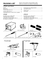
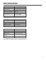
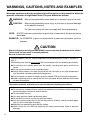
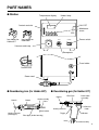
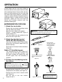
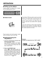
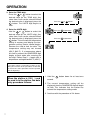
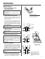
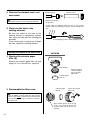
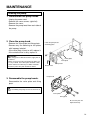
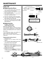
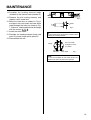
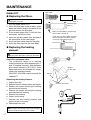
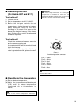
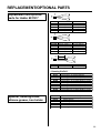
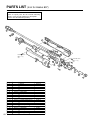
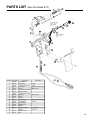
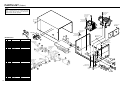
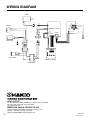
®
472-01 IRON TYPE
472-02 GUN TYPE
Desoldering Tool
Instruction Manual
●
Thank you for purchasing the Hakko 472D desoldering tool
with digital temperature display.
Please read this manual before operating the Hakko 472D.
Keep this manual readily accessible for reference.
●
CAUTION
Before Plugging In!
REMOVE the pump securing screw (M4 × 25, red) from the
bottom of the 472D station before using it. Leaving the screw
in place will cause serious problems. Be sure to SAVE THIS
SCREW!
REPLACE the pump securing screw (M4 × 25, red) into the
bottom of the 472D station before transporting it. Leaving the
screw out will cause serious problems.
TABLE OF CONTENTS
PACKING LIST/SPECIFICATIONS ................................................ 1
WARNINGS, CAUTIONS, NOTES AND EXAMPLES ................... 3
PART NAMES ............................................................................... 4
OPERATION .................................................................................. 5
PARAMETER SETTING .............................................................. 11
MAINTENANCE .......................................................................... 12
ERROR MESSAGES ................................................................... 19
BEFORE SERVICING ...... .......................................................... 19
TROUBLESHOOTING GUIDE .................................................... 20
REPLACEMENT/OPTIONAL PARTS .......................................... 22
PARTS LIST (IRON FOR HAKKO 807) ....................................... 23
PARTS LIST (GUN FOR HAKKO 817) ........................................ 24
PARTS LIST (STATION) .............................................................. 25
WIRING DIAGRAM ...................................................................... 27
Please check to make sure that all items listed
below are included in the Hakko 472D package.
PACKING LIST
472D-01 and 472D-02
Station ............................................................. 1
Spring filter ...................................................... 3
Ceramic paper filter (S) ................................... 2
Ceramic paper filter (L) ................................... 4
Cleaning pin for ø1.0 mm (0.04 in.) nozzle..... 1
Cleaning pin for heating element .................... 1
Instruction manual .......................................... 1
Control card .................................................... 1
Card chain ....................................................... 1
472D-01
472D-02
Desoldering iron (Hakko 807) ......................... 1
Filter pipe with filter holder,
spring filter & ceramic paper filter (L) ............. 1
Iron holder for Hakko 807 ............................... 1
Desoldering gun (Hakko 817) ......................... 1
Filter pipe with front holder,
spring filter & ceramic paper filter (L) ............. 1
Iron holder for Hakko 817 ............................... 1
Station
Control card/Card chain
Spring filter
Ceramic paper filter (S)
Cleaning pin for heating element
Cleaning pin for ø1.0 mm (0.04 in.) nozzle
For pen type
For gun type
Desoldering iron (Hakko 807)
Iron holder
1
Ceramic paper filter (L)
Filter pipe
Desoldering gun (Hakko 817)
Iron holder
Filter pipe
SPECIFICATIONS
Station
Hakko 472D
Power consumption
120V AC, 110W
Vacuum pressure
80 KPa (600 mmHg) (24 in.Hg)
Suction flow
15 liters/min
Nozzle to ground potential
Under 2 m V
Nozzle to ground resistance
Under 2 Ω
Outer dimensions (l × w × h)
263 × 160 × 148 mm
(10.4 × 6.3 × 5.8 in.)
Weight (w/o cord)
4.6 kg (10.14 lb.)
Desoldering iron
Hakko 807
Power consumption
24V AC, 60W
Temperature range
350 - 450°C (662 - 842°F)
Standard nozzle
A1003 (1.0 mm/0.04 in.)
Total length (w/o cord)
205 mm (8.07 in.)
Weight (w/o cord)
Approx.160 g (0.35 lb.)
Desoldering iron
Hakko 817
Power consumption
24 VAC, 60 W
Temperature range
350 - 450°C (662 - 842°F)
Standard nozzle
A1003 (1.0 mm /0.04 in.)
Outer dimensions (W × H)
(w/o cord)
135 × 145 mm (5.31 × 5.71 in.)
Weight (w/o cord)
Approx. 180 g. (0.39 lb.)
*Specifications and design subject to change without notice.
2
WARNINGS, CAUTIONS, NOTES AND EXAMPLES
Warnings, cautions and notes are placed at critical points in this manual to direct the
operator’s attention to significant items. They are defined as follows:
WARNING: Misuse may potentially cause death of, or serious injury to the user.
CAUTION:
Misuse may potentially cause injury to the user or physical damage
to the objects involved.
For your own safety, be sure to comply with these precautions.
NOTE:
A NOTE indicates a procedure or point that is important to the process being
described.
EXAMPLE: An EXAMPLE is given to demonstrate a particular procedure, point or
process.
CAUTION
×25, marked red) from the bottom of the station.
Remove the pump securing screws (M4×
Failure to do so may result in serious problems.
Be sure to save this screw.
When the power is on, the nozzle temperature will be between 350°C/662°F and 450°C/
842°F.
Mishandling may lead to burns or fire. Be sure to comply with the following precautions.
● Do not touch the metallic parts near the nozzle, nearby plastic parts and the iron
holder .
● Do not use the product near flammable items.
● Advise other people in the work area that the unit can reach a very high temperature
and should be considered potentially dangerous.
● Turn the power off when no longer using the Hakko 472D or leaving it unattended.
● Before replacing parts or storing the unit, turn the power off and allow the unit to cool
to room temperature.
To prevent accidents and failures, be sure to take the following precautions:
● Do not use the unit for applications other than desoldering.
● Do not rap the desoldering iron against the workbench to shake off residual solder, or
otherwise subject the iron to severe shocks.
● Do not modify the unit.
● Use only genuine Hakko replacement parts.
● Do not wet the unit or use the unit with wet hands.
● Use the ceramic paper filter (S) for the filter retainer (station), and the ceramic paper
filter (L) for the filter pipe (iron/gun).
● Maintain the desoldering gun and the station.
● While using the unit, don’t do anything that could cause bodily harm or physical
damage.
3
PART NAMES
● Station
Temperature display
Heater lamp
Control card slot
CAL POT
Membrane
sheet
UP
Iron holder for
Hakko 817
Iron holder for
Hakko 807
CAL
DOWN
VACUUM
IRON
POWER
Power switch
Vacuum outlet cap
Receptacle
Fuse holder
Control card
Power cord
● Desoldering iron (for Hakko 807)
● Desoldering gun (for Hakko 817)
Filter Pipe
Nozzle
Cord assembly
Nozzle
Button
Hose
Heating element
Heating element
(Inside pipe)
Back holde
assembly
Release
Knob
Back holder
Trigger
Indicator
Filter pipe (Inside housing)
Hose
Cord assembly
4
OPERATION
Heated solder and flux can cause oxides to
form and adhere to the nozzle and the inside
of the heating element. These oxides not only
lower the heat conductivity, but can also clog
the nozzle and heating element, resulting in
a drop in suction efficiency. Should there be a
noticeable drop in suction efficiency during
operation, replace the filter and clean the
nozzle and heating element with the
provided cleaning pin.
(Figure 1)
● PREPARATION FOR USE.
1. Attach the iron holder.
Remove the iron holder mounting screws
from the side of the station.
Attach the iron holder to the station.
(Figure 1 shows Hakko 807; figure 2
shows Hakko 817.)
(The iron holder can be installed on the
either the left or right side.)
(Figure 2)
CAUTION:
Be sure to use appropriate iron holder for 807 or 817.
Misuse may damage the desoldering iron/gun.
2. Attach the desoldering tool
Hakko 807 desoldering iron:
Insert the filter pipe (with a filter holder,
spring filter and ceramic paper filter (L))
into the housing.
Push and turn the back holder clockwise.
(Figure 3)
(Figure 3)
Insert the cord
assembly by keying
the plug to the key
on the receptacle.
VACUUM
Hakko 817 desoldering gun.
The desoldering gun for Hakko 817
comes with the filter pipe installed. This
filter pipe includes the spring filter and
ceramic paper filter. No assembly is
required.
Attach the hose securely
over the vacuum outlet
cap.
(Figure 5)
3. Connect the desoldering tool to
the station.
Secure the plug by
turning it clockwise.
(Figure 4)
CAUTION:
Be sure the power switch is OFF ( ) before
connecting the desoldering iron cord. Failure to do
so may result in damage to circuit board.
• Connect the cord assembly of the
desoldering tool (Hakko 807 or 817) to the
receptacle on the station (see Figure 4).
• Connect the hose to the vacuum outlet
cap. (Figure 5)
• Set the tool in the iron holder.
(Figure 6 and 7)
5
(Figure 7) Side view
(Figure 6) Top view
CAUTION
ALWAYS place the tool in the
holder when not in use.
OPERATION
● Setting up the station.
Factory settings: The Hakko 472D is shipped
with the following preset values:
Temperature scale
°F
Low temperature alarm setting
120
Set temperature
750
● Control card
Each Hakko 472D comes with a small card, which
inserts in the control slot in the front of the unit.
This card is used when entering data for the
process control functions. Any Hakko 472D card
can be used with any Hakko 472D soldering
station.
This card is used when a value is to be changed or
data are to be entered. The Hakko 472D will
operate normally with the card inserted. Remove
the control card to lock the data.
Plug the power cord into the power supply
and turn the power switch to ON ( ).
● Setting/changing the
temperature.
1. Insert the card into the card slot in the
front panel of the station.
• The HUNDREDS digit in the display
begins to flash, indicating that the station
is in the temperature setting mode and
data can be entered.
2. Enter the HUNDREDS digit.
• Use the
or
button to select the
desired value for the HUNDREDS digit.
For setting in degrees Celsius, either 3 or
4 can be selected. For settings in degrees
Fahrenheit, values between 6 and 8 can
be selected. When the desired value is
displayed, press the
button.
Example :
Change the temperature from 700°F to 840°F
Insert the card.
Press the UP or DOWN button.
Press the
button once.
6
OPERATION
3. Enter the TENS digit.
• Press the
or
button to select the
desired value for the TENS digit. Any
value from 0 to 9 can be selected. When
the desired value is displayed, press the
button. The UNITS digit begins to
flash.
4. Enter the UNITS digit.
• Use the
or
button to select the
desired value for the UNITS digit. Any
value from 0 to 9 can be selected. When
the desired value is displayed, press the
button. This will store the temperature
setting in memory and display the temperature setting. Heater control begins.
Remove the card to lock the data. The
temperature setting may not exceed
450°C (842°F). If a temperature above
this limit is entered, the HUNDREDS digit
begins to flash again after entering the
last digit. Follow step 2 - 4 again with a
temperature setting below 842°F (450°C).
Press the UP or DOWN button.
Press the
button once.
Press the
button once.
NOTE:
If the power switch is turned off, or power is lost
during the execution of this procedure, no data will
be entered. The entire procedure must be repeated
from the beginning.
When the station is ON ( ) and
the card is in the station, the data
entry procedure follows:
1. Hold the
second.
button down for at least one
2. The current temperature setting will be
displayed, then the HUNDREDS digit will begin
to flash. This indicates that the station has
entered the temperature setting mode.
3. Continue with the procedure of 2-4 above.
7
OPERATION
● Desoldering
1. Set the temperature. See
preceding section.
NOTE:
Always set the temperature as low as possible for the
work being done.
The temperature can be adjusted between 350 450°C (662 - 842°F).
2. Clean the tip of the nozzle.
Keep the tinned section of the nozzle
clean and shiny by coating it with a small
amount of solder.
If the tip of the nozzle is coated with oxide,
the nozzle’s heat conductivity will be
lowered. Coating the tip with a small
amount of fresh solder ensures maximum
heat conductivity.
NOTE:
Holder and sponge are not included with the Hakko 472D.
3. Melt the solder.
Sponge (Optional parts)
Wipe away any oxide or old solder
from the nozzle using the hole in
the center of the sponge.
Nozzle
P.W.B.
Solder
Lead
• Apply the nozzle to the soldered part and
melt the solder.
NOTE:
Never allow the nozzle to touch the board itself.
• Confirm that the solder is melted.
NOTE:
• To confirm that all the solder is melted, observe the
inside of the hole and the backside of the P.W.B. If
this is difficult to do, try slowly moving the lead with
the nozzle. If the lead moves, the solder is melted.
• Never move the lead by force.
If the lead does not move easily, the solder has not
fully melted.
4. Extract the solder.
After confirming that the solder is
completely melted, extract the solder by
pushing the button on top of the 807
desoldering iron, or pressing the trigger
switch on the 817 desoldering gun.
Slowly move the
lead with the nozzle.
NOTE:
Never leave any solder remaining inside the hole in
the P.W.B.
5. Problems during desoldering.
If solder remains, resolder the component
and repeat the desoldering process.
Extract the solder by slowly
moving the lead back and
forth with the tip of the nozzle
whilst holding the button or
trigger.
8
Filter indicator (Hakko 817 only the Hakko 807 does not have
such an indicator)
With the nozzle hole clear, pull the trigger
and look at the indicator. If it is red, clean
the nozzle and heating element, empty
the filter pipe, and/or replace the filters. If
the indicator is blue, cleaning is not
necessary and operations can be
resumed.
NOTE
The indicator will not operate properly if the hole of
the nozzle is plugged, or if the solder in the hole of
the board being worked has not melted.
Not required
Blue or slight
amount of red
can be seen.
Required
Solution
If the indicator is more
than half red, replace the
filter and clean the nozzle
and the inside of the
More than half heating element. (refer to
of the indicator p.12 Maintenance of the
is red.
Desoldering iron)
CAUTION:
Any time there is a noticeable drop in suction efficiency,
first clean the nozzle and heating element with the cleaning
pin. If the drop persists, replace the filters on the 817 AND
station.
Replacing the filter.
Replace the filter as shown 1 - 3 . During
operation, the filter pipe is very hot. Wait
until the filter pipe is cool before replacing
the filter. We recommend keeping a
second filter pipe containing new filters
handy, and replacing the installed filter
pipe with this backup filter pipe.
3
Replace the entire filter pipe
with the provided backup filter pipe.
2
Pull
1
Down
9
Problems during
desoldering
1. The solder in the
junction is not
sufficiently melted.
• Temperature is not high enough. Many assemblies require a
greater heat capacity to desolder, including multilayer P.W.B.s,
power supplies, ground planes in through-hole P.W.B.s, highcapacity transistors, triacs with heat radiation fins, tuner
P.W.B. ground wires, and large-scale transformer terminals.
Use a pre-heater, such as the Hakko 853, or other heat source
to heat the P.W.B. to a temperature between 70-80°C. (160180°F.) that will not damage the board or its components, then
desoldering. Do not increase the temperature of the gun by
recalibration as this may damage the P.W.B. and its
components.
2. The nozzle is worn
out.
• When the nozzle begins to wear out, the heating efficiency
begins to decline. Check the nozzle. If the solder plating is
damaged, or the nozzle is eroded, replace the nozzle.
3. Suction power is
dropping.
• Replace the filters, and clean the nozzle and the inside of the
heating element, as described in the section on maintenance.
4. Air is leaking from
the vacuum system.
Check the air-tightness of the following parts and replace any
that are worn.
a. Contact point of the
nozzle and heating
element. (for Hakko 807
& 817)
b. Front holder and nearby
parts. (for Hakko 807 &
817)
c. O-ring in the back holder
(for Hakko 817 only)
d. Hose (for Hakko 807 &
817)
e. Vacuum outlet cap (for
Hakko 807 & 817)
f. Packing and nearby parts
(for Hakko 817 only)
NOTE:
Air leakage cannot be determined from the indicator (for Hakko 817 only)
Post-operation
maintenance.
To ensure a long service life,
always perform the following
maintenance procedures
immediately after using the
Hakko 472D unit.
● Remove all solder from the inside of the nozzle and heating
element. Refer to MAINTENANCE, p.12.
● Clean the tip of the nozzle with the cleaning sponge, then coat
the tip with a fresh layer of solder to protect the solder plating.
10
PARAMETER SETTING
The HAKKO 472D has the following parameters. Parameter settings can be adjusted.
1. °C or °F temperature display selection.
2. Low temperature tolerance.
3. Display of room temperature compensation value (test mode)
Once parameter input mode has been entered, set the parameters in the order shown below. After all
the parameters have been set, normal operation will be resumed.
1. °C (Celsius) or
°F (Fahrenheit)
temperature display.
1. Turn off the power switch.
2. Insert the control card into the slot in the station.
3. Press and hold the
and
buttons simultaneously, then
turn on the power switch.
4. Continue holding down the
and
buttons until the
display shows °C (for Celsius) or °F (for Fahrenheit).
5. When the display shows °C or °F, the station is in parameter
input mode.
6. Pressing the
or
button will cause °C or °F to be
displayed alternately.
7. Press the
button to select the scale. The low temperature
tolerance may now be entered.
2. Low temperature
tolerance.
(Flashing of the
temperature display)
When the station enters the ‘low temperature tolerance’ setting
mode, the HUNDREDS digit will begin flashing. Enter and store
the value in the same manner as described in ‘Changing the
temperature setting’.
Range of allowable heater error temperatures
For °C: 30 – 150°C
For °F: 60 – 300°F
If a temperature value outside this range is selected, the display
will again flash the HUNDREDS digit. If this happens, reenter a
correct temperature value.
After setting the low temperature tolerance value, the display will
show the room temperature compensation value (test mode).
3. Room temperature
compensation value.
(Test Mode)
The display will not blink and the heater will not receive power.
The room temperature compensation value is the measured
temperature of the nozzle. This function will be used later to
calibrate the nozzle temperature. (See “Recalibrate the temperature” on P.18)
No inputs are made here. Press
to complete parameter
input. The nozzle temperature setting will be displayed for 2
seconds, after which power will be supplied to the heater and
normal temperature control will begin.
11
MAINTENANCE
Efficient desoldering depends upon the temperature, the quality and quantity of the
solder and flux. Perform the following service procedures as dictated by the conditions
of use.
During maintenance, please wear gloves and work carefully.
WARNING:
Since the desoldering iron/gun can reach a very high temperature, please work carefully. Except when
cleaning the nozzle and heating element, always turn the power switch off and disconnect the power plug
before performing any maintenance procedure.
Servicing the Desoldering iron
Cleaning with the nozzle cleaning pin.
1. Inspect and clean the nozzle.
• Plug in the power cord, turn the power
switch “ON” and let the nozzle heat up.
• Clean out the hole of the nozzle with the
nozzle cleaning pin.
If the nozzle cleaning pin does not pass
through the nozzle, use the cleaning drill
(option).
NOTE:
• The cleaning drill is not included.
• The cleaning pin will not pass through the nozzle
until the solder inside the nozzle is completely
melted.
• Verify that the correct cleaning pin is used for the
nozzle. The inside diameter of the nozzle is
stamped on the side of the nozzle.
The cleaning pin passes
completely through the hole.
Cleaning with the cleaning drill (option).
• Before cleaning
Insert the bit while turning it clockwise.
• After cleaning
Pull the drill bit out straight without turning it.
• Check the condition of the solder plating,
surface and inside hole of the nozzle.
If it is slightly worn, recoat the tip with
fresh solder.
• If it is worn or eroded, or the inside
diameter seems unusually wide, replace
the nozzle.
NOTE:
The inside hole and the surface of the nozzle is
plated with a special alloy.
Should this alloy become eroded by high
temperature solder, the nozzle will not be able to
maintain the proper temperature.
• If the cleaning pin or cleaning drill do not
pass through the hole in the nozzle,
replace the nozzle.
solder plating
CAUTION
If the cleaning drill is forced
into the nozzle, the drill bit
could break or be damaged.
CAUTION
Please use the proper sized
cleaning pin or cleaning drill
for the nozzle diameter.
Diameter of hole is
widened through erosion.
NOTE:
Unfortunately, it is often difficult to observe this condition,
therefore, if desoldering efficiency goes down and all
other parts appear to be OK,
the nozzle is probably eroded
and should be replaced.
12
2. Remove the element cover, nut
and nozzle.
Element cover
Heating element
Nozzle
CAUTION:
The heating element is very hot during operation.
3. Clean out the hole in the
heating element.
Be sure the solder in the hole in the
heating element is completely melted,
then clean the hole with the cleaning pin
provided.
If the cleaning pin cannot pass through
the hole, replace the heating element.
Cleaning the inside of the filter case
Nut
Remove the nut with
the spanner.
Scrape away all oxidation from the hole in the heating
element until the cleaning pin passes cleanly through the
hole.
The cleaning pin passes cleanly through the hole.
VACUUM
1. Replace the ceramic paper
filter (S).
Remove the ceramic paper filter (S) and
inspect it. If it is stiff with flux, replace it.
Filter retainer
Remove the filter
retainer and push
out the ceramic
paper filter.
Ceramic paper
filter (S)
2. Reassemble the filter case.
Ceramic paper
filter (S)
Secure the vacuum
outlet cap.
CAUTION:
Insert the SMALL ceramic paper filter into the filter
retainer at the station. Using the large ceramic paper
filter may damage the unit, or reduce the effectiveness of the unit.
Apply silicone grease to the O-ring
(S-20) and securely tighten the
vacuum outlet cap to prevent air
leakage.
13
MAINTENANCE
Cleaning the pump
1. Disassemble the pump heads.
• Unplug the power cord.
• Remove the cover screws. (right/left)
• Remove the cover.
• Remove the pump head from each side of
the pump.
2. Clean the pump head.
• Remove the valve plate and fixing plate.
• Remove any flux adhering to the plates
with isopropyl alcohol.
• If the valve plate is bent or stiff, replace it.
• If the exhaust filter is dirty, replace it.
CAUTION:
• If the fixing plate is difficult to remove, apply hot air
to warm it.
• Never use excessive force to remove the plate as it
is easy to bend, and a bent plate will allow a leak,
which reduces the efficiency of solder extraction.
• Clean the plates only with alcohol or thinner.
Clean the pump head
and fixing plate.
Fixing plate
Valve plate
Pump head
Exhaust filter
Pump head
3. Reassemble the pump heads.
Reassemble the valve plate and fixing
plate.
CAUTION:
When assembling the pump, be sure to check for air
leaks.
Valve plate
Fixing plate
Be sure the parts are
aligned correctly.
14
MAINTENANCE
Hakko 807
● Replacing the filters.
Ceramic paper filter(L)
1. Turn the back holder knob counterclockwise and pull out the filter pipe.
2. If there is solder in two-thirds of the spring
filter, replace the filter.
3. If the ceramic paper filter is stiff with flux
and solder, replace the filter.
4. Insert the spring filter into the filter pipe.
5. Insert the ceramic paper filter and put the
back holder into the filter pipe.
6. Insert the filter pipe into the main body
and secure it by turning the back holder
knob clockwise.
Spring Ffilter
Filter holder
Filter pipe
Back holder
Front holder
Filter holder
Spring filter
CAUTION
Securely insert the spring filter to
the end of the filter holder.
● Replacing the
heating element.
Pins
Check the resistance value.
The resistance values of a working heating
element are 9.2Ω between pins 1 and 3 (heating
element), 54Ω between pins 2 and 4 (sensor) at
73°F (23°C).
If the measured values are outside this
range, replace the heating element.
(No. A1174 24V-60W heating element for
Hakko 807)
1
4
3
2
Nut
Fig. 1
Nozzle
Element cover
Fig. 2
Replacing the heating element.
1. Unplug the cord.
2. Remove the nut, element cover, and
nozzle.
3. Turn the back holder knob counterclockwise and pull out the filter pipe.
4. Remove the housing fastener.
5. Remove the screws securing the housing
9 and the screws 3 4 securing the
flange to the housing.
6. Remove the front holder.
7. Remove the screw 5 6 7 securing the
heating element to the flange, and the
screw 1 2 .
24V
60W
Fastener
Fig. 3
Back holder knob
9
Front holder
9
5
3
1
7
6
2
24V
60W
4
Fig. 4
15
MAINTENANCE
8. Desolder the heating element leads
(marked H) and sensor leads (marked S).
9. Remove the old heating element and
replace it with a new one.
10. Bend the lead wire as shown in Fig. 6,
and pass two red leads and two white
leads through the holes as shown in Fig.
7. Secure a heating element to the flange
with the screws 5 6 7 .
11. Install the front holder.
12. Resolder the heating element leads (red
wires/H) sensor leads (white wires/S).
13. Reassemble the unit.
S
S
H
H
Fig. 5
Wires
Fig. 6
CAUTION
Be careful not to twist and pull the lead wire when
installing the heating element.
Pass the leads
through the holes
as shown.
Flange
Two
red leads
Two
white leads
Fig. 7
NOTE:
Be sure the insulation on the leads touches the
board. Do not leave any bare wire exposed.
16
MAINTENANCE
Hakko 817
● Replacing the filters.
CAUTION:
The filter pipe is very hot.
Front holder
Ceramic Paper
Filter (L)
Spring filter
Ceramic Paper
Filter (L)
1. Turn the power switch OFF.
2. When the filter pipe is cool to touch, push
down the release knob at the back of the
gun and remove the filter pipe.
3. If the ceramic paper filter is stiff with flux
and solder, replace the filter.
4. Insert the ceramic paper filter and attach
the spring filter to the front holder.
5. Insert the front holder into the filter pipe.
6. Insert the filter pipe into the main body.
Attach the front holder to the filter pipe
so that it does not leak air.
Firmly press the back holder assembly
into the filter pipe in order to property
seat the O-ring against the pipe.
● Replacing the heating
element.
WARNING:
Unplug the power cord before starting this procedure.
Check the resistance value
The resistance values of a working
heating element are 9.2Ω between pins 1
and 3 (heating element), 54Ω between
pins 2 and 4 (sensor) at 73°F (23°C). If the
measured values are outside this range,
replace the heating element.
(No.A1507 24V-60W heating element for
Hakko 817)
Replacing the heating element.
1. Unplug the cord.
2. Remove the nut, element cover and nozzle.
3. Remove the screws securing the heating
element to the housing.
4. Remove the screws securing the housing
and separate the housing.
5. Remove the packing.
6. Detach the terminal.
7. Remove the old heating element and
replace it with a new one.
8. Reassemble the unit.
CAUTION:
Be sure to place the packing to prevent air escaping.
Failure so to do will cause a loss in suction.
17
Remove
the filter pipe.
Housing
Unscrew the screws.
Packing
● Replacing the cord
(For Hakko 807 and 817)
Test method 1
CAUTION:
The heater lamp will flicker if the iron/gun
temperature is allowed to reach the set
temperature. Before replacing the cord, be sure
that this is not the reason for the flickering.
1. Turn the unit on.
2. Set the temperature to 450°C (842°F).
3. Before the iron/gun reaches the set
temperature, wiggle the cord at various
points along the length of the cord,
including in the strain relief area at the
base of the iron/gun housing. If the heater
lamp flickers, the cord is broken and
should be replaced.
Test method 2
Check the resistance between each pin
on the connecting plug and
its associated wire on the terminal board
inside the housing.
All measured vales should be 0Ω. If any
value is greater than 0Ω, replace the cord.
Pins
6
5
1
2
3
4
Figure 2.
Desoldering station connector
Pin 1 – Black
Pin 2 – White
Pin 3 – Red
Pin 4 – White
Pin 5 – Green
Pin 6 – Blue
CAUTION:
There are two white wires. Check another combination if
the first one is not 0.
● Recalibrate the temperature
(a) Set the desired temperature.
(b) Adjust the temperature calibration pot
(CAL) until the nozzle temperature
(measured with a thermometer) is
correct.
CAUTION:
Never set the nozzle temperature above the
maximum temperature. It will cause problems.
18
ERROR MESSAGES
Various error messages will be displayed when there is a problem with the Hakko 472D
unit. If the following message is displayed, refer to “TROUBLESHOOTING GUIDE”.
System Error
After the power has been turned on, the system
checks the memory and the programs. If an
abnormality is found,
will be displayed, and
all operations will be completely stopped.
Sensor Error
If there is a possibility of a failure in the sensor or
anywhere in the sensor circuit,
will be
displayed and power to the desoldering iron will be
cut off.
The sensor error also occurs if the cord assembly
is not properly connected.
Low temperature tolerance
If power is present at the desoldering tool and the
nozzle temperature goes below the heater error
temperature tolerance setting, the temperature
display will flash. This indicates the possibility of a
heater malfunction.
(Flashing of the temperature display)
EXAMPLE:
Assume the temperature setting is 400°C (750°F)
and the low temperature tolerance is 50°C
(100°F). If, even though the heater is receiving
power, the temperature of the desoldering iron
goes below 350°C (650°F) the display will begin to
flash, indicating a possible heater malfunction.
EXAMPLE:
400 – 50°C = 350°C; (750 – 100°F = 650°F)
→ The display will begin to flash.
NOTE:
If the temperature begins to rise again, the display will stop
flashing – even if the displayed temperature is below 350°C
(650°F).
BEFORE SERVICING ......
WARNING:
• Disconnect the power plug before servicing.
Failure to do so may result in electric shock.
• If the power cord is damaged, it must be replaced by the manufacturer, its authorised
service agent, or a similarly qualified technician to avoid hazard.
19
TROUBLESHOOTING GUIDE
Troubleshooting Guide
● Power lamp does not light up.
• Is the power cord plugged in correctly?
Securely insert the power cord into the power
supply.
• Is the fuse blown?
Investigate why the fuse blew and then replace the
fuse. If the cause can not be determined, replace the
fuse. If the fuse blows again, send the unit in for
repair.
Example Is the inside of the gun short-circuited?
● Pump does not operate.
• Is the cord assembly properly
connected?
Reconnect the cord assembly. (Refer to the
appropriate paragraphs under ‘Maintenance’.)
• Is the nozzle or hole in the heating
element clogged?
Clean it. (Refer to the appropriate paragraphs under
‘Maintenance’.)
● Solder is not being absorbed.
• Is the spring filter full of solder?
Replace it with a new one. (Refer to the appropriate
paragraphs under ‘Maintenance’.)
• Is the ceramic filter hardened?
Replace it with a new one.
• Is there a vacuum leak?
Check the connections and replace any worn parts.
● The nozzle does not heat up.
• Is the desoldering iron/gun cord
assembly properly connected?
Reconnect it.
• Is the heating element damaged?
Replace it. (Refer to the appropriate paragraphs
under ‘Maintenance’.)
Note : When repairs are needed please send both the
desoldering iron/gun and the station to your sales agent
or American Hakko.
20
● System Error
displayed.
is
● Sensor Error
displayed.
is
Call your Hakko representative.
• Is the iron/gun cord plugged in
correctly?
Insert the plug securely into the receptacle.
• Is the iron/gun cord good?
Replace the cord. (Refer to the appropriate
paragraphs under ‘Maintenance’.)
• Is the heating element good?
Replace the heating element. (Refer to the
appropriate paragraphs under ‘Maintenance’.)
● Low temperature tolerance
is displayed frequently.
(Flashing of the temperature display.)
• Is the setting value for the low
temperature tolerance too low?
21
Increase the setting value.
øB
Replacement and optional
parts for Hakko 807/817
øA
REPLACEMENT/OPTIONAL PARTS
øA
0.8 mm (0.03 in.)
1.0 mm (0.04 in.)
1.0 mm (0.04 in.)
1.3 mm (0.05 in.)
0.6 mm (0.02 in.)
øB
2.3 mm (0.09 in.)
2.0 mm (0.08 in.)
1.6 mm (0.06 in.)
2.3 mm (0.09 in.)
1.5 mm (0.06 in.)
øA
0.8 mm (0.03 in.)
1.0 mm (0.04 in.)
1.3 mm (0.05 in.)
1.6 mm (0.06 in.)
2.3 mm (0.09 in.)
øB
2.3 mm (0.09 in.)
2.5 mm (0.1 in.)
3.0 mm (0.12 in.)
3.0 mm (0.12 in.)
4.0 mm (0.16 in.)
øB
øA
Part No.
A1002B
A1003B
A1393B
A1395B
A1487B
Part No.
A1004B
A1005B
A1006B
A1007B
A1396B
øB
øA
11 mm (0.43 in.)
Part No.
A1394B
øA
1.0 mm (0.04 in.)
øB
2.3 mm (0.09 in.)
• Cleaning Pin/Drill
Part No.
B1215
B1086
B1087
B1088
B1089
B1302
B1303
B1304
B1305
Spanner, cleaning brush,
silicone grease, iron holder
Part No.
B2100
B1670
A1028
B2729
B2832
A1319
Part name/Description
Cleaning pin for heating element
Cleaning pin for ø0.8 mm (0.03 in.) nozzle
Cleaning pin for ø1.0 mm (0.04 in.) nozzle
Cleaning pin for ø1.3 mm (0.05 in.) nozzle
Cleaning pin for ø1.6 mm (0.06 in.) nozzle
Cleaning drill for ø0.8 mm (0.03 in.) nozzle
Cleaning drill for ø1.0 mm (0.04 in.) nozzle
Cleaning drill for ø1.3 mm (0.05 in.) nozzle
Cleaning drill for ø1.6 mm (0.06 in.) nozzle
Part name/Description
Spanner (for 807/817)
Cleaning brush
Silicone grease
Iron holder for 807
Iron holder for 817
Packing for Hakko 817
22
PARTS LIST (Iron for Hakko 807)
NOTE:
Spare or repair parts do not include mounting
screws, if they are not listed on the description.
Screws must be ordered separately.
12
16
15
17
13
11
19
8
9
10
Pan head screw
M2.6 × 7 (1)
Sus
7
14
Pan head screw
M2.6 × 7 (7)
Sus
18
5
6
3
1
2
4
Item No.
1
2
3
4
5
6
7
8
9
10
11
12
13
14
15
16
17
18
19
23
Part No.
B1653
A1174
B1015
B1654
A1304
A1030
B1655
B1656
B1916
A1033
B1657
B1917
B1659
B1023
B1024
B1660
B1915
B2517
Part Name
Description
Nozzle
See P.15
Element cover
Heating element
24V-60W
Nut
Flange
Front holder
Spring filter
Set of 10
Button
Board
With switch
Filter pipe
Ceramic paper filter (L)
Set of 10
Cord assembly
Back holder assembly
Housing
With a screw & fastener
Hose
Cord holder
Set of 4
Housing fastener
Filter holder
Filter pipe asse’y With filter holder & filters
PARTS LIST (Gun for Hakko 817)
1
2
4
3
6
5
Pan head screw
M2.6 × 10 (1)
with washer
Sus
20
19
18
7
11
17
8
Pan head screw
M2.6 × 7 (2)
Sus
9
16
15
14
12
10
Item No.
1
2
3
4
5
6
7
8
9
10
11
12
13
14
15
16
17
18
19
20
Part No.
A1314
A1030
A1033
B2073
A1012
B1018
B1019
B1020
B2830
B1023
A1319
B2831
B1024
B1022
B1026
B1021
A1507
B1653
B1015
Part Name
Front holder
Spring filter
Ceramic paper filter (L)
Filter pipe
O-ring
Back holder assembly
Release knob
Spring for release knob
Housing
Hose
Packing
Cord assembly
Cord holder
Cord stopper
Micro switch
Trigger
Heating element
Nozzle
Element cover
Nut
Description
13
10pcs.
10pcs.
With front holder & filters
With O-ring
With screws
With micro switch & plug
Set of 4
"24V, 60W"
See P.22
24
PARTS LIST (Station)
NOTE:
Spare or repair parts do not include mounting
screws, if they are not listed on the description.
Screws must be ordered separately.
Pan head screw
with washer
M4 × 30
Pan head screw
with washer
M4 × 8 (4)
Truss screw
Ni
M4 × 5 (8)
External tooth
lock washer
Nominal size 4
16
17
Pan head screw
with washer
M3 × 6 (8)
Spacer
Nominal size
4 × 25
Pan head screw
with washer
M4 × 6
Truss screw
M4 × 5 (4)
External tooth
lock washer
Nominal size 4
21
18
21
22
23
24
25
26
27
28
29
30
31
32
33
34
35
36
37
25
Part No.
Part Name
B1029
A1009
B1063
B1034
B1031
B1064
B1662
B1084
B1204
B2724
B2314
B2726
B2727
B2047
B2388
B2444
B2728
B1041
B1275
B2068
Vacuum outlet cap
Ceramic paper filter (S)
Filter retainer
O-ring
Vacuum outlet retainer
Filter case joint
Receptacle
Power switch
Rubber foot
Chassis
Hose assembly
P.W.B. for display
P.W.B. for heat control
Membrane sheet
Control card
Pump assembly
Transformer
Fuse holder
Fuse
Power cord, 3 core &
American plug
Cover
Iron holder
Balance weight
Crank
Damper
Ring for bearing
Crank shaft
Pump flame
Motor
Diagram
Diagram setting plate
Fixing plate
Valve plate
Pump head
Exhaust filter
Filter retaining pin
Iron holder
B2725
B2729
B1053
B1312
B2506
B1057
B2060
B2059
B2058
A1013
B2085
B1056
A1014
B1050
B1059
B1313
B2832
12
Pan head screw
with washer
M4 × 6
37
● 472D Station
Item
No.
1
2
3
4
5
6
7
8
9
10
11
12
13
14
15
16
17
18
19
20
13
Set of 10
S-20
With O-ring & screws
19
22
Description
Pan head screw
with washer
M3 × 6
External tooth
lock washer
Nominal size 4
23
24
Pan head screw
with washer
M3 × 6 (4)
25
20
27
26
With rubber foot
11
28
250V-2A (U)
Pan head screw
with washer
M4 × 12 (8)
32
With screw
35
36
10
8
30
31
33
Set of 2
29
Flat head
screw
M4 × 12 (2)
34
7
Flat head screw
M4 × 8 (4)
Spring washer
Nominal size 4 (4)
Hexagon nut
M4 (4)
14
9
6
Pan head screw
M4 × 25
2
5
4
15
3
1
Set of 2, with screws
Set of 2
With screws
Set of 2
for 817
26
WIRING DIAGRAM
Motor
Switch
2
2
1
1
1
5
Iron
2
P.W.B. for control
CN2
1
3
4
3
CN1
CN3
Power cord
1
4
1
3
CN2
1
CN1
4
Fuse holder
P.W.B. for display
Transfomer
HEAD OFFICE
4-5, SHIOKUSA 2-CHOME, NANIWA-KU, OSAKA, 556-0024 JAPAN
TEL:+81-6-6561-3225 FAX:+81-6-6561-8466
http://www.hakko.com/
AMERICAN HAKKO PRODUCTS, INC.
28920 N. AVENUE WILLIAMS VALENCIA CA 91355, U.S.A.
TEL: (661) 294-0090 FAX: (661) 294-0096
Toll Free (800)88-HAKKO www.hakkousa.com
4 2 5 5 6
27
Nov. 2002
MA01080JU021106


![Instruction Manual - [HAKKO] Document Portal](http://vs1.manualzilla.com/store/data/005882531_1-c17999a04ed3b96f12c2eb288800f74b-150x150.png)