1
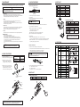
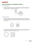
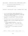
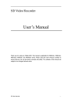
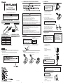
4. WARNINGS, CAUTIONS, NOTES AND EXAMPLES
WARNING
Instruction Manual
CAUTION
●HAKKO FX-8804 can not be operated by itself. Read the instruction manual for the
HAKKO FX-888D soldering station used in conjunction with the HAKKO FX-8804.
●Do not set the temperature 400℃(752℉) or more.
1
1
Please make sure that all items listed
below are included in the package.
Heat resistant pad
Instruction manual
Do not operate this station
over 400℃(752℉) with
FX-8804 SMD HOT TWEEZER.
●HAKKO FX-8804
Power consumption
Temperature range
Tip to ground resistance
Tip to ground potential
Length of cord
Length (w/o cord)
Weight (w/o cord)
Heat resistant pad
Caution label
HAKKO FX-8804
2. SPECIFICATIONS
1
1
Tip
(Chip 2L)
Handle
3. COMPATIBLE STATIONS
AC 26V 65W
200 400℃ (400~752℉)
<2Ω
<2 mV
1.2 m (47.2in.)
186 mm (7.3in)
93 g (0.21lb.)
Push on the plug
until it stops,
making sure
it is securely
connected.
receptacle
1. Connect the cord assembly of HAKKO FX-8804
to the receptacle of HAKKO FX-888D.
Thank you for purchasing the HAKKO FX-8804 SMD Hot Tweezer
Please read this manual before operating the HAKKO FX-8804.
Keep this manual readily accessible for reference.
HAKKO FX-8804
Caution label
A. Connection
Be sure to turn off the power before connecting
or disconnecting the cord assembly for
the iron to and from the receptacle to avoid
damaging the unit.
SMD HOT TWEEZER
1. PACKING LIST AND PART NAMES
6. OPERATION
Use the HAKKO FX-8804 with the HAKKO
FX-888/888D soldering station.
When power is ON, tip temperature will be between 200℃ and 400℃ (400 to 752℉).
To avoid injury or damage to personnel and items in the work area, observe the following :
● Do not touch the tip or metal parts near the tip
● Do not allow the tip to come close to, or touch, flammable materials.
● Inform others in the area that the unit is hot and should not be touched.
● Turn the power off when not in use, or left unattended.
● Turn the power off when changing parts or storing the HAKKO FX-8804.
● This appliance is not intended for use by persons (including children) with reduced physical,
sensory or mental capabilities, or lack of experience and knowledge, unless they have been
given supervision or instruction concerning use of the appliance by a person responsible for their safety.
● Children should be supervised to ensure that they do not play with the appliance.
● Do not use the HAKKO FX-8804 for applications other than desoldering.
● When you use the HAKKO FX-8804 for the first time, note that calibration is recommended.
● Do not set the temperature above 400℃ (752℉).
● Do not strike the iron against hard objects to remove excess solder. This will damage the iron.
● Do not modify the HAKKO FX-8804.
● Use only genuine HAKKO replacement parts.
● Do not allow the HAKKO FX-8804 to become wet, or use it when hands are wet.
● Remove power and iron cords by holding the plug - not the wires.
● Since smoke is produced when using the HAKKO FX-8804, be sure the work area is well ventilated.
● While using HAKKO FX-8804, do not do anything which may cause bodily harm or physical damage.
5. ASSEMBLY
1. Put the caution label on the HAKKO FX-888D
soldering station.
NOTE :
The HAKKO FX-8804 can not be used at
temperature above 400℃(752℉). If setting
the temperature over 400℃(752℉), the station
will result in accidents or damage.
2. Attach the heat resistant pad.
Pass the iron cord through the hole in the
heat resistant pad. Use it when removing the tips.
NOTE:
※Specifications and design are subject to change without notice.
※This product is protected against electrostatic discharge.
This product includes such features as electrically conductive plastic parts and grounding of the unit
as measures to protect the device to be soldered from the effects of static electricity. Be sure to observe
the following instructions:
1. The plastic parts are not insulators, they are conductors. When making repairs or replacing
parts, take sufficient care not to expose live electrical parts or damage insulation materials.
2. Be sure to ground the unit during use.
Dial type label only
Put the label above the temperature
indicator lines.
Do not operate this station
over 400℃(752℉) with
FX-8804 SMD HOT TWEEZER.
Put the label in a visible area such as
the front or top panel of the station.
2. Place the iron into the iron holder.
3. Plug the power cord into the power supply.
B. Turn on the power switch
Turn on the power for HAKKO FX-888D soldering station.
The heater lamp flashes as the tip comes up to the set temperature.
The unit is now ready to perform soldering work.
●Place the HAKKO FX-8804 in the iron holder when not in use.
●Turn the power off when not using the station for a long time.
C. Calibration
Before using the HAKKO FX-8804, be sure to calibrate the station.
(Refer to the HAKKO FX-888D instruction manual.)
Use HAKKO FG-100 Thermometer or HAKKO FG-101
Soldering Tester to measure the tip temperature.
When calibrating the tip, place the edge of the tip on
the measuring point of the HAKKO FG-100 or FG-101.
1. Temperature setting
Tip for SOP
Very high tip temperature may damage
the P.W.B., possibly causing the printed
pattern to become detached.
Recommend setting the temperature
depending on work conditions.
Setting the lowest possible effective
temperature helps protect parts that
are sensitive to heat and extends tip
life.
●Never set the temperature to any value
over 400℃(752℉). Doing so may damage the station.
●Set the temperature depending on the type
of work to be done.
●Refer to the HAKKO FX-888D instruction manual
for setting the temperature.
2. Apply solder or flux.
If there is not enough solder on the P.W.B.
or the soldered area is too small,
apply the solder or flux to the P.W.B.
Solder wets to the tip.
(Fig.1)
If you use the iron holder for FH-800 included with HAKKO FX-888D,
remove the iron receptacle and insert the holder clip (not included) as the figure below indicates.
Solder
Holder clip
4. Remove the component.
After confirming that the solder is fully melted,
hold the tweezer lightly to lift the
component, and remove it. (Fig. 2)
Instruction manual in the language of Japanese, English, Chinse, French, German and Korean
can be downloaded from the HAKKO Document Portal.
(Please note that some languages may not be available depending on the product.)
Tip for Chip
●Removing components
3. Melt the solder
Place the tip on the soldered part and
melt the solder. Confirm the solder is fully
melted. (Fig.1)
●Iron holder
To disconnect, hold the plug.
(Fig. 2)
Never force the component or squeeze with excessive
force as this may damage the work and/or tips.
●Replacing the tip
The tip may be hot. Avoid holding the hot tip for a long time even if using the
heat resistant pad. Otherwise burns may result.
1. Turn the nipple counterclockwise and loosen it.
NOTE :
Do not remove the nipple.
2. Insert the new tip into the HAKKO FX-8804.
When the tips click, they are fully inserted.
Using the holder clip, attach the tip parallel
to other tip.
Copyright © 2012 HAKKO Corporation. All Rights Reserved.
2012.10
MA02040XZ121001
3. Tighten the nipple firmly, fix the tip.
7. MAINTENANCE
Performing proper and periodic maintenance extends product life and contributes to the
quality of soldering work. Efficient soldering depends upon the temperature, the quality and quantity of
the solder and flux. Apply the following service procedure as dictated by the conditions of the usage.
8. CHECK PROCEDURE
Cleaning
Always clean the tip before use to remove any residual solder or flux adhering to it.
Use a cleaning sponge or the HAKKO 599B tip cleaner.
Contaminants on the tip may have negative effects, including reduced heat conductivity,
which contribute to poor performance.
● HAKKO FX-8804
1. Broken heating element / sensor
Sensor (Blue)
1. Loosen the nipple by turning it counterclockwise.
2. Pull out the tip.
3. Remove the screw and strut pin. Separate into handle A and B.
Remove the tension spring.
4. Remove each tapping screw of the handle A and B, and remove the handle cover.
5. Pull out the P.W.B. and heating element.
After use
*Measure when the heating element is at room temperature.
1. Heating element resistance (red) 2.5-4.5 Ω
2. Sensor resistance (blue) 43-58 Ω
If the resistance value is not normal, replace the heating element.
(Refer to the instructions included with the replacement part.)
Always clean the tip and coat it with fresh solder after use. This guards against oxidation.
●Tip Maintenance
1. Set the temperature to 250℃(482℉).
2. When the temperature stabilizes, clean the tip and
check the condition of the tip. If the tip is badly worn or deformed, replace it.
3. If the solder plated part of the tip is covered with black oxide, apply fresh solder,
containing flux, and clean the tip again. Repeat until all the oxide is removed,
then coat the tip with fresh solder.
4. Turn the power OFF and remove the tip, using the heat resistant pad. Set the tip aside to
cool.
After replacement
1. Measure the resistance between pins 4 and 1, 4 and 2, 5 and 1, 5 and 2.
If it is not ∞, the heating element and sensor are touching. This will damage the circuit board.
2. Measure the resistance “a” , “b” and “c” to confirm that the leads are not twisted and that
the grounding spring is properly connected.
● If the values of “a” and ”b” are outside
the value in the table, replace the heating
element(sensor) and/or cord assembly.
2.5 ~ 4.5 Ω
a. Between pins 4 & 5
The power lamp starts to flash when the temperature reaches 400℃(752℉)
regardless of the condition of the cord.
b. Between pins 1 & 2 (Sensor)
43 ~ 58 Ω
c. Between pin 3 & tip
2 or less Ω
2. Check the resistance between the plug pin and the terminal lead.
Pin 1: Red Pin 2: Blue Pin 3 : Green
Pin 4 : White Pin 5 : Black
If it is higher than 0 Ω or ∞, the cord should be replaced.
● If the value of “c” is over the value in the
table, remove the oxidization film by lightly
rubbing with sand-paper or steel wool
the points shown in the drawing on the right.
Rub lightly with sand-paper or
steel wool.
Handle B
Nut
●HAKKO FX-8804 Hot Tweezer
Item No.
1∼6
Part No.
FX8804-02
Part Name
HAKKO FX-8804
6
Tension spring
4
2
Handle A
3
Tip
Be sure to measure the resistance of the heating element in both handles A and B.
If one of the heating elements is broken, replace both heating elements.
Specifications
AC26V 65W
5
Strut pin
Screw
Nipple
10. TIP STYLES
For
CHIP
For
SOP
9. PARTS LIST
1
7
Part No.
Part Name
A1559 Cleaning sponge
B3666 Holder clip
B3475 Bottom plate with
protection plate
Specifications
with Protective Sheet
& rubber foot
CAUTION
(at time of room temperature)
(heating element)
holder parts
Specifications
Blue-Yellow
Silver
For safety reasons, please attach the protective sheet
to the bottom plate when using the HAKKO FX-8804.
Item No.
1. Turn the power on and set the temperature control knob to 400℃(752℉). Then, bend the cord
at various locations along its length, including in the strain relief area.
If the LED heater lamp flashes, then the cord needs to be replaced.
Disconnect the plug of the cord assembly
and measure the resistance value
between the pin of the connecting plug as follows.
Specifications
See”TIP STYLES”
2 PCS.
● Iron
Item No.
1
2
3
There are two methods of testing the cord assembly as below.
8. CHECK PROCEDURE
A1578
B2289
B2290
B2295
B2296
B2300
Part Name
Tip
Heating element
Nipple
Terminal
Tension spring
Strut pin
Heat resistant pad
● HAKKO FH-800 Iron holder
Item No. Part No.
Part Name
1 ∼ 3 FH800-04BY HAKKO FH-800
1 ∼ 3 FH800-04SV HAKKO FH-800
2. Broken cord assembly
Do not file the tip in an attempt to remove the black oxide.
Part No.
Do not lose the tension spring.
When not in use
Never allow the unit to idle at a high temperature for extended periods. This will allow the
tip to become oxidized. Turn the power switch OFF. If it is to be out of service for
several hours, it is advisable to disconnect the power plug as well.
Item No.
1
2
3
4
5
6
7
Heating element (Red)
WARNING
Since the tip can reach a very high temperature, please work carefully.
Except where indicated, always turn the power switch OFF and disconnect the power plug
before performing any maintenance procedure.
Tip temperature
High temperatures shorten tip life and may cause thermal shock to components.
Always use the lowest possible temperature. The excellent thermal recovery characteristics
of the HAKKO FX-888D ensures effective soldering at low temperature.
9. PARTS LIST
Part Name
Size A(B)
A1577
Tip /CHIP 0.5L
0.5 mm
A1379
Tip /CHIP 1L
1 mm
A1378
Tip /CHIP 2L
2 mm
A1388
Tip /CHIP 0.5C
1.5(0.5)
A1389
Tip /CHIP 0.5I
R0.25
A1576
Tip /CHIP 2.6C
2.6
A1390
Tip /SOP 4L
4 mm
A1391
Tip /SOP 6L
6 mm
A1380
Tip /SOP 8L
8 mm
A1381
Tip /SOP 10L
10 mm
A1382
Tip /SOP 13L
13 mm
A1392
Tip /SOP 15L
15 mm
A1383
Tip /SOP 18L
18 mm
A1384
Tip /SOP 20L
20 mm
A1385
Tip /SOP 25L
25 mm
Shape