1
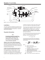
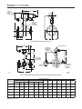
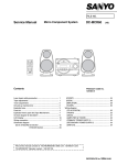
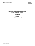
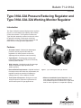
Bulletin 71.2:310A
January 2009
Type 310A-32A Pressure Reducing Regulator and
Type 310A-32A-32A Working Monitor Regulator
Introduction
The Type 310A pilot-operated high-pressure regulator
(Figure 1) is used where high capacity and accurate
control are essential. This regulator includes one
Type 32A pilot assembly mounted on the main valve
for pressure reducing or wide-open monitoring
applications, or two Type 32A pilots mounted on the
main valve for working monitor applications.
Features
• Accurate Control—Molded pilot diaphragms provide a narrow proportional band and registration of outlet pressure on the main
diaphragm allows excellent control sensitivity.
• Tight Shutoff—Throttling-sleeve design with Polytetrafluoroethylene (PTFE) seat in the body ensures positive shutoff.
• High Capacity—Straight-through flow passage
allows exceptionally high capacities and stable operation.
W6278
Figure 1. Type 310A Regulator with Type 32A Pilot
• Fast Speed of Response—Designed to meet stringent speed of response requirements for turbine startup and fuel gas applications.
• Minimum Installation Space Required—Since main valve design incorporates actuator spring, less installation space is needed for the Type 310A than for other regulators of comparable capacity.
D102066X012
• Reduced Relief Requirements—Optional restricted trim helps reduce relief valve size requirements; the
regulator is easily converted to full capacity by changing the trim, if flow conditions increase.
www.emersonprocess.com/regulators
Bulletin 71.2:310A
Specifications
Available Configurations
Type 310A-32A: Type 310A main valve with one Type 32A pilot for standard pressure-reducing and wide-open monitoring applications
Type 310A-32A-32A: Type 310A main valve with two Type 32A pilots for working monitor applications
Body Sizes and End Connection Styles
1-inch body with NPT ends; and 1, 2, 3, 4, or 4 x 6-inch (DN 25, 50, 80, 100, and
100 x 150) body with CL300 RF or
CL600 RF flanged ends
Maximum Inlet and Pilot Supply Pressures(1)
NPT and CL600 RF: 1500 psig (103 bar)
CL300 RF: 750 psig (51,7 bar)
Maximum Pressure Drop(1)
NPT and CL600 RF: 1425 psig (98,3 bar) CL300 RF: 720 psig (49,6 bar)
Maximum Outlet Pressure(1)
Operating: 700 psig (48,3 bar)
To Avoid Internal Part Damage: 800 psig (55,2 bar)
Exceeding this pressure may result in gas venting from pilot spring case.
Emergency (Casing): 1500 psig (103 bar) or maximum inlet pressure whichever is lower.
Outlet Pressure Ranges and Proportional Bands
See Table 1
Maximum Travel
See Table 3
Minimum Differential Pressure(1)
15 psig (1,0 bar)
Flow Coefficients
See Tables 4, 5, and 6
IEC Sizing Coefficients
See Table 7
Flow Capacities
See Tables 8, 9, 10, 11, and 12
Maximum Temperature Capabilities(1)
Nitrile (NBR) with Wiper Ring:
-20° to 150°F (-29° to 66°C)
Fluorocarbon (FKM) with Wiper Ring:
0° to 150°F (-18° to 66°C)
Fluorocarbon (FKM) without Wiper Ring:
0° to 300°F (-18° to 149°C)
External Pilot Supply Connection
1/4-inch NPT
Pilot Vent Connection
1/4-inch NPT
Pressure Connections
See Figure 9
Options
• Main valve body without pilot for on-off service
• Remote-mounted pilot
• Electrically controlled pilot using Type 662 Kixcel™
• Travel indicator
• Pressure loaded pilot
• Type 252 pilot supply filter
• Backpressure protection system
• Restricted Trim (30%, 50%, or 70%)
• NACE construction
• Inlet tap
Approximate Weights
1-inch (DN 25): 45 pounds (20 kg)
2-inch (DN 50): 90 pounds (41 kg)
3-inch (DN 80): 145 pounds (66 kg)
4-inch (DN 100): 190 pounds (86 kg)
4 x 6-inch (DN 100 x 150): 235 pounds (107 kg)
Construction Materials
Main Valve
Body: WCC steel
Throttling Sleeve: Stainless steel
Seat: PTFE
Diaphragm Plates: Steel
Diaphragm and O-rings: Nitrile (NBR) (standard) or Fluorocarbon (FKM)
Main Spring: Steel
Valve Plug: Stainless steel
Travel Indicator Rod: Stainless steel
Wiper Ring: Nitrile (NBR)
Pilot
Spring Case, Diaphragm Spacer, Pilot Body, and Spring Case Cap: Cast steel
Adjusting Screw and Diaphragm Plate: Plated steel
Diaphragm: Nitrile (NBR) (standard) or Fluorocarbon (FKM)
Orifice Assembly and Yoke: Stainless steel
Valve Disk Assembly: Stainless steel/Nitrile (NBR) (standard) or Stainless steel/Fluorocarbon (FKM) Bleed Valve and Orifice: Stainless steel
Piston and Piston Seat Assembly: Stainless steel and Nylon (PA)
Pilot Main Spring: Plated steel
1. The pressure/temperature limits in this bulletin or any applicable standard limitation should not be exceeded.
2
Bulletin 71.2:310A
PILOT DIAPHRAGM PLATE
AND YOKE ASSEMBLY
PILOT Control
spring
BLEED VALVE
FIXED
RESTRICTION
BOTTOM
DIAPHRAGM
RELAY SEAT
TOP DIAPHRAGM
MAIN VALVE DIAPHRAGM
THROTTLING SLEEVE
MAIN VALVE SPRING
E0696
STATIONARY
VALVE PLUG
INLET PRESSURE
OUTLET PRESSURE
atmospheric pressure
LOADING PRESSURE
PILOT SUPPLY PRESSURE
Figure 2. Type 310A-32A Regulator Operational Schematic
Principle of Operation
Single-Pilot Regulator (Figure 2)
The regulator inlet pressure enters the pilot through
the external pilot supply line and is utilized as the
supply pressure for the pilot. The setting of the
pilot control spring determines the reduced outlet
(downstream) pressure.
In operation, assume the outlet pressure is less than
the setting of the pilot control spring. Pilot control
spring force then overcomes the force resulting from
outlet pressure acting on the bottom diaphragm.
The spring pushes the diaphragm plate and yoke
assembly away from the relay seat, opening it and
supplying additional loading pressure to the main
valve diaphragm. When this additional loading
pressure exceeds the force resulting from outlet
pressure acting on the main valve diaphragm plus
the force of the main valve spring, the diaphragm is
pushed away from the stationary valve plug. The
throttling sleeve opens wider, and the required gas is
supplied to the downstream system.
When gas demand in the downstream system has
been satisfied, the outlet pressure tends to increase. The increased outlet pressure acting on the bottom
diaphragm of the diaphragm plate and yoke assembly
results in a force that overcomes the pilot spring
setting and forces the assembly toward the relay
seat, closing it. The loading pressure acting on the
main valve diaphragm bleeds to the downstream
system through the fixed restriction in the diaphragm
plate and yoke assembly. When rapid main valve
closure is required by unusual control conditions,
the bleed valve opens for increased bleed rate. The
force of increased outlet pressure acting on the main
valve diaphragm plus the main valve spring force
overcomes the force of decreased loading pressure
acting on the main valve diaphragm and moves the
3
Bulletin 71.2:310A
E0694
E0695
Figure 3. Typical Wide-Open Monitor
Figure 4. Typical Working Monitor
throttling sleeve toward the stationary valve plug to
decrease the gas flow to the downstream system.
of the Type 32A monitoring pilot. A plug in both the
working and monitoring pilots makes the internal
bleed nonfunctional. A restriction placed in the
external tubing between the diaphragm loading
pressure and the intermediate pressure acts as a
downstream bleed.
The top diaphragm in the pilot acts as a sealing
member for the loading chamber and as a balancing
member to the bottom diaphragm. The two
diaphragms are connected by a yoke. Pressure
change to the center chamber has little effect on the
positioning of the valve disk.
Monitor Systems
Wide-Open Monitors (Figure 3)
Monitoring regulators serve as overpressure protection
devices to limit system pressure in the event of failure
of working regulators feeding the system. The control
line of a wide-open monitoring regulator may be
connected downstream of the working regulator, so
that during normal operation the wide-open monitoring
regulator is standing wide open with the pressure
reduction being taken across the working regulator.
Only in case of working regulator failure does the
wide-open monitoring regulator operate.
Working Monitors (Figures 4 and 5)
The Type 310A-32A-32A working monitor regulator
differs from wide-open monitors in that it has working
monitor capability. This means that it normally
reduces pressure and throttles while the second-stage
regulator is in operation. Should the second-stage
working regulator fail open, the Type 310A-32A-32A
will take over the entire pressure reduction function.
The working monitor pilots are adaptations of two
Type 32A pilots with special internal parts, due to
the pressure conditions in this piloting system. A
spacer blocks open the differential regulator portion
4
If the second-stage working regulator fails to open,
the distribution pressure increases to the setting of
the Type 32A monitoring pilot (slightly higher than
the original distribution pressure) and is controlled
at that level by the Type 310A-32A-32A. Thus,
downstream equipment is protected against a major
overpressure condition without disrupting service or
venting gas to atmosphere.
In the working pilot, the inlet pressure is reduced
to a pre-determined pilot supply pressure, which is
further reduced to loading pressure for the Type 310A
diaphragm. The loading pressure is piped through
the portion of the monitoring pilot blocked open by the
spacer and, as long as distribution pressure is below
the setting of the monitoring pilot, passes through the
relay orifice of the monitoring pilot to the diaphragm
case of the Type 310A body.
Distribution pressure is piped back to the monitoring
pilot. As long as the distribution pressure is less than
the monitoring pilot setting, the working pilot controls
the Type 310A to maintain intermediate pressure. If
the distribution pressure increases to the monitoring
pilot setting, the monitoring pilot relay orifice starts
to throttle the loading pressure to the Type 310A
diaphragm. This allows the Type 310A main spring
to move the throttling sleeve closer to the seat and
control distribution pressure at the monitoring pilot set
point. Therefore, failure of the second-stage working
regulator is controlled with only a slight increase in
distribution pressure, with the Type 310A-32A-32A
accomplishing the entire pressure reduction function.
Bulletin 71.2:310A
WORKING PILOT
PLUG
RESTRICTION
SPACER
E0693
INLET PRESSURE
PLUG
MONITORING PILOT
OUTLET PRESSURE
ATMOSPHERIC PRESSURE
LOADING PRESSURE
INTERMEDIATE PRESSURE
PILOT SUPPLY PRESSURE
Figure 5. Type 310A-32A-32A Working Monitor Regulator Operational Schematic
Table 1. Outlet Pressure Ranges
OUTLET PRESSURE RANGE, PSIG (bar)
SPRING COLOR
SPRING PART NUMBER
10 to 20 (0,69 to 1,4)
PROPORTIONAL BAND, PSIG (bar)
0.5 (0,03)
Silver
1D809627022
10 to 100 (0,69 to 6,9)
2 (0,14)
Yellow
1E392527022
100 to 250 (6,9 to 17,2)
5 (0,34)
Blue
1D387227022
250 to 600 (17,2 to 41,4)
12 (0,83)
Red
1D465127142
400 to 700 (27,6 to 48,3)(1)
20 (1,4)
Green
13A5543X012
1. Available with Nitrile (NBR) pilot diaphragm only.
Table 2. Recommended Minimum Differential Between Monitoring Pilot Setting and Distribution Pressure
OUTLET PRESSURE RANGE, PSIG (bar)
SPRING COLOR
SPRING
PART NUMBER
MINIMUM PRESSURE AT WHICH
MONITORING PILOT CAN BE SET, PSIG (bar)
10 to 20 (0,69 to 1,4)
Silver
1D809627022
3.0 (0,21) over normal distribution pressure
10 to 100 (0,69 to 6,9)
Yellow
1E392527022
5.0 (0,34) over normal distribution pressure
100 to 250 (6,9 to 17,2)
Blue
1D387227022
10 (0,69) over normal distribution pressure
250 to 600 (17,2 to 41,4)
Red
1D465127142
15 (1,0) over normal distribution pressure
400 to 700 (27,6 to 48,3)
Green
13A5543X012
20 (1,4) over normal distribution pressure
5
Bulletin 71.2:310A
LOADING TUBING
HAND VALVE
1/4-INCH NPT PILOT
SUPPLY CONNECTION
VENT VALVE
LOCATE 6 TO 10 PIPE
DIAMETERS FROM
VALVE OUTLET
VENT VALVE
BLOCK VALVE
HAND VALVE
BLOCK VALVE
ALTERNATE
DOWNSTREAM
CONTROL LINE TAP
1/2-INCH (13 mm)
DOWNSTREAM CONTROL LINE
BYPASS VALVE
VENT VALVE
BYPASS LINE
24B4134
B2444
Figure 6. Typical Pressure Reducing Installation
Installation
The Type 310A may be installed in any position, but is
normally installed in a horizontal pipeline with the pilot
or pilots above the body. See Figures 6, 7, and 8 for
typical piping installation.
Capacity Information
Note
Type 310A regulator flow capacities
are laboratory verified; therefore, they
may be sized for 100% flow using
capacities as shown in Tables 8, 9,
10, 11, and 12. It is not necessary to
reduce published capacities.
Tables 8, 9, 10, 11, and 12 show the natural gas
regulating capacities of the Type 310A regulator at
selected inlet pressures and outlet pressure settings.
Flows are in thousands of SCFH at 60°F and 14.7 psia
(and in thousands of Nm3/h at 0°C and 1,01325 bar) of
0.6 specific gravity natural gas.
To determine equivalent capacities for air, propane,
butane, or nitrogen, multiply the capacity by the
following appropriate conversion factor: 0.775 for
air, 0.628 for propane, 0.548 for butane, or 0.789
for nitrogen. For gases of other specific gravities,
multiply the given capacity by 0.775, and divide by the
square root of the appropriate specific gravity. Then,
6
if capacity is desired in normal cubic meters per hour
at 0°C and 1,01325 bar, multiply SCFH by 0.0268.
To find approximate regulating capacities at pressure
settings not given in Tables 8, 9, 10, 11, and 12 or
to find wide-open flow capacities for relief sizing
at any inlet pressure, perform one of the following
procedures. Then, if necessary, convert using the
factors provided above.
For critical pressure drops (absolute outlet pressure
equal to or less than one-half of absolute inlet
pressure), use the following formula:
Q = (P1)(Cg)(1.29)
For pressure drops lower than critical (absolute
outlet pressure greater than one-half of absolute
inlet pressure).
Q =
520 3417
P
CgP1SIN DEG
GT
C1
P1
where,
Q = gas flow rate, SCFH P1 = absolute inlet pressure, psia
(P1 gauge + 14.7)
Cg = regulating or wide-open gas sizing coefficient from Table 4, 5, or 6 G = gas specific gravity of the gas T = absolute temperature of gas at inlet, °Rankine
C1 = flow coefficient P = pressure drop across the regulator, psi
Bulletin 71.2:310A
24B4134
B2445_2
FLEXIBLE WIDE-OPEN MONITOR ARRANGEMENT THAT PERMITS
WIDE-OPEN MONITOR TO BE EITHER UPSTREAM OR
DOWNSTREAM OF THE WORKING REGULATOR
MINIMUM PIPING WIDE-OPEN MONITOR ARRANGEMENT THAT
REQUIRES WIDE-OPEN MONITOR ALWAYS TO BE
UPSTREAM OF WORKING REGULATOR
Figure 7. Typical Wide-Open Monitor Installation
Table 3. Maximum Travel
BODY SIZE, INCHES (DN)
MAXIMUM TRAVEL, INCH (mm)
1 (25)
0.5 (13)
2 (50)
0.875 (22)
3 (80)
1 (25)
4 (100)
1.125 (28)
4 x 6 (100 x 150)
1.5 (38)
A0714_2
Figure 8. Typical Working Monitor Installation
Table 4. Wide-Open Flow Coefficients for Relief Valve Sizing with Body Size Piping for Relief Valve Sizing
BODY SIZE, INCHES (DN)
TRIM SIZE
30%
50%
70%
100%
1 (25)
2 (50)
3 (80)
4 (100)
Cg
238
835
1810
3080
4 x 6 (100 x 150)
4400
Cv
8.6
30.6
64.6
114.9
181.8
C1
27.7
27.3
28
26.8
24.2
Cg
313
1240
2810
4620
6600
Cv
10.3
46.3
99.3
172.4
280.9
C1
30.4
26.8
28.3
26.8
23.5
Cg
----
1800
3780
6660
9000
Cv
----
69
129
213
360
C1
----
26.2
29.3
31.3
25
Cg
612
2610
5510
8830
16200
Cv
22
95
200
322
661
C1
28.1
27.5
27.5
27.4
24.5
7
Bulletin 71.2:310A
Table 5. Regulating Flow Coefficients for Body Size Piping
COEFFICIENT
AT PERCENT
OF MAXIMUM
TRAVEL
10%
20%
30%
40%
50%
60%
70%
80%
90%
100%
TRIM SIZE (PERCENT OF FLOW CAPACITY) BY BODY SIZE, INCHES (DN)
1 (25)
2 (50)
3 (80)
4 (100)
4 x 6 (100 x 150)
100%
50%
30%
100%
70%
50%
30%
100%
70%
50%
30%
100%
70%
50%
30%
100%
70%
50%
Cg
65
60
56
210
200
190
185
346
340
325
305
805
725
615
510
895
800
780
30%
760
Cv
2.2
2.0
2.0
7.6
7.5
6.9
7.0
12.5
11.6
11.3
10.8
29.6
24.0
22.6
19.2
41.6
32.0
33.2
31.4
Cg
115
93
83
460
396
311
260
810
735
615
460
1800
1310
1040
705
2235
1680
1420
1160
Cv
4.0
3.2
3.0
16.6
14.9
11.3
9.8
29.3
25.2
21.4
16.3
66.2
43.4
38.2
26.6
104.0
67.2
60.4
47.9
Cg
210
124
107
810
583
430
325
1520
1120
85
606
3100
1990
1480
917
3800
2550
2050
1550
Cv
7.3
4.2
3.8
29.2
21.9
15.6
12.3
55.1
38.4
3.0
21.4
114.0
65.9
54.4
34.6
176.7
102.0
87.2
64.0
Cg
343
151
126
1120
758
540
385
2380
1480
1130
755
4350
2650
1900
1130
5510
3300
2650
1940
Cv
11.9
5.1
4.5
40.4
28.5
19.6
14.6
86.2
50.7
39.4
26.7
159.9
87.7
69.9
42.6
256.3
132.0
112.8
80.2
Cg
427
178
140
1440
925
646
444
3270
1840
1380
902
5480
3280
2300
1340
7300
4150
3250
2330
Cv
14.8
6.0
5.0
52.0
34.8
23.4
16.8
118.5
63.0
48.1
31.9
201.5
108.6
84.6
50.6
339.5
166.0
138.3
96.3
Cg
485
204
150
1750
1090
744
502
3890
2190
1630
1060
6310
3950
2730
1540
9010
5010
3840
2720
112.4
Cv
16.8
6.9
5.4
63.2
41.0
27.0
19.0
140.9
75.0
56.8
37.5
232.0
130.8
110.4
58.1
419.1
200.4
163.4
Cg
523
226
159
2040
1240
841
561
4410
2540
1880
1210
7040
4550
3140
1740
10580
5870
4430
3110
Cv
18.2
7.7
5.7
73.6
46.6
30.5
21.3
159.8
87.0
65.5
42.8
258.8
150.7
115.4
65.7
492.1
234.8
188.5
128.5
Cg
549
250
168
2260
1400
946
624
4820
2900
2130
1360
7640
5110
3540
1950
12100
6720
5030
3500
Cv
19
8
6
82
53
34
24
175
99
74
48
281
169
130
74
563
269
214
145
Cg
573
272
177
2430
1550
1040
690
5080
3210
2380
1510
8140
5700
3950
2200
13600
7570
5650
3870
Cv
20
9
6
88
58
38
26
184
110
83
53
299
189
145
83
633
303
240
160
Cg
597
289
184
2520
1700
1130
761
5330
3530
2640
1670
8670
6390
4390
2680
14900
8450
6320
4120
Cv
C1
21
10
7
91
64
41
29
193
121
92
59
319
212
161
101
693
338
269
174
28.8
29.5
28
27.7
26.6
27.6
26.4
27.6
29.2
28.7
28.3
27.2
30.2
27.2
26.5
24.5
25
23.5
24.2
Table 6. Regulating Flow Coefficients for 2:1 Swaged Piping and 100% Trim
TRIM SIZE (PERCENT OF FLOW CAPACITY) BY BODY SIZE, INCHES (DN)
COEFFICIENT AT PERCENT
OF MAXIMUM TRAVEL
10%
20%
30%
40%
50%
60%
70%
80%
90%
100%
1 (25)
2 (50)
3 (80)
4 (100)
Cg
60
210
340
810
4 x 6 (100 x 150)
850
Cv
2.0
7.1
11.6
28.1
29.8
Cg
115
450
825
1700
2050
Cv
3.8
15.2
28.3
59.0
71.9
Cg
205
795
1540
3050
3300
115.8
Cv
6.7
26.8
52.7
105.9
Cg
330
1110
2350
4300
4650
Cv
10.8
37.4
80.5
149.3
163.2
Cg
395
1380
3025
5400
6050
Cv
13.0
46.5
103.6
187.5
212.3
Cg
450
1610
3550
6200
7430
Cv
14.8
54.2
121.6
215.3
260.7
Cg
490
1800
3900
3900
8700
Cv
16.1
60.6
133.6
135.4
305.3
Cg
515
1960
4200
7400
9860
Cv
17
66
144
257
346
Cg
533
2055
4440
7800
10800
Cv
17
69
152
271
379
Cg
548
2140
4610
8150
11600
Cv
18
72
158
283
407
30.5
29.7
29.2
28.8
28.5
C1
Table 7. IEC Sizing Coefficients
8
BODY SIZE, INCHES (DN)
1 (25)
2 (50)
3 (80)
4 (100)
4 x 6 (100 x 150)
Xt
0.53
0.49
0.48
0.47
0.29
FD
0.66
0.59
0.56
0.48
0.58
FL
0.74
0.74
0.74
0.74
0.74
Bulletin 71.2:310A
Table 8. 1-inch (DN 25) Body Capacities with 100% Trim and Body Size Piping (Thousands of SCFH (Nm3/h)) of 0.6 Specific Gravity Gas)
INLET
PRESSURE,
PSIG (bar)
Outlet Pressure, Psig (bar)
25 (1,7)
50 (3,5)
48 (1,3)
50 (3,5)
75 (5,2)
100 (6,9)
125 (8,6)
150 (10,3)
175 (12,1)
200 (13,8)
225 (15,5)
250 (17,2)
300 (20,7)
75 (5,2)
69 (1,8)
100 (6,9)
88 (2,4)
61 (1,6)
87 (2,3)
73 (1,9)
150 (10,3)
127 (3,4)
127 (3,4)
125 (3,4)
115 (3,1)
92 (2,5)
200 (13,8)
165 (4,4)
165 (4,4)
165 (4,4)
163 (4,4)
156 (4,2)
139 (3,7)
107 (2,9)
250 (17,2)
204 (5,5)
204 (5,5)
204 (5,5)
204 (5,5)
202 (5,4)
195 (5,2)
182 (4,9)
160 (4,3)
121 (3,2)
300 (20,7)
243 (6,5)
243 (6,5)
243 (6,5)
243 (6,5)
242 (6,5)
240 (6,4)
234 (6,3)
223 (6,0)
206 (5,5)
178 (4,8)
350 (24,1)
281 (7,5)
281 (7,5)
281 (7,5)
281 (7,5)
281 (7,5)
281 (7,5)
278 (7,5)
273 (7,3)
263 (7,1)
248 (6,6)
195 (5,2)
400 (27,6)
320 (8,6)
320 (8,6)
320 (8,6)
320 (8,6)
320 (8,6)
320 (8,6)
319 (8,5)
317 (8,5)
312 (8,4
303 (8,1)
272 (7,3)
450 (31,0)
358 (9,6)
358 (9,6)
358 (9,6)
358 (9,6)
358 (9,6)
358 (9,6)
358 (9,6)
358 (9,6)
355 (9,5)
350 (9,4)
331 (8,9)
500 (34,5)
397 (10,6)
397 (10,6)
397 (10,6)
397 (10,6)
397 (10,6)
397 (10,6)
397 (10,6)
397 (10,6)
396 (10,6)
393 (10,5)
381 (10,2)
550 (38,0)
435 (11,7)
435 (11,7)
435 (11,7)
435 (11,7)
435 (11,7)
435 (11,7)
435 (11,7)
435 (11,7)
435 (11,7)
434 (11,6)
427 (11,4)
600 (41,4)
474 (12,7)
474 (12,7)
474 (12,7)
474 (12,7)
474 (12,7)
474 (12,7)
474 (12,7)
474 (12,7)
474 (12,7)
474 (12,7)
470 (12,6)
650 (44,8)
512 (13,7)
512 (13,7)
512 (13,7)
512 (13,7)
512 (13,7)
512 (13,7)
512 (13,7)
512 (13,7)
512 (13,7)
512 (13,7)
511 (13,7)
700 (48,3)
551 (14,8)
551 (14,8)
551 (14,8)
551 (14,8)
551 (14,8)
551 (14,8)
551 (14,8)
551 (14,8)
551 (14,8)
551 (14,8)
551 (14,8)
750 (51,7)
589 (15,8)
589 (15,8)
589 (15,8)
589 (15,8)
589 (15,8)
589 (15,8)
589 (15,8)
589 (15,8)
589 (15,8)
589 (15,8)
589 (15,8)
800 (55,2)
628 (16,8)
628 (16,8)
628 (16,8)
628 (16,8)
628 (16,8)
628 (16,8)
628 (16,8)
628 (16,8)
628 (16,8)
628 (16,8)
628 (16,8)
850 (58,6)
666 (17,8)
666 (17,8)
666 (17,8)
666 (17,8)
666 (17,8)
666 (17,8)
666 (17,8)
666 (17,8)
666 (17,8)
666 (17,8)
666 (17,8)
900 (62,1)
705 (18,9)
705 (18,9)
705 (18,9)
705 (18,9)
705 (18,9)
705 (18,9)
705 (18,9)
705 (18,9)
705 (18,9)
705 (18,9)
705 (18,9)
950 (65,5)
744 (19,9)
744 (19,9)
744 (19,9)
744 (19,9)
744 (19,9)
744 (19,9)
744 (19,9)
744 (19,9)
744 (19,9)
744 (19,9)
744 (19,9)
1000 (68,9)
782 (21,0)
782 (21,0)
782 (21,0)
782 (21,0)
782 (21,0)
782 (21,0)
782 (21,0)
782 (21,0)
782 (21,0)
782 (21,0)
782 (21,0)
1100 (75,8)
859 (23,0)
859 (23,0)
859 (23,0)
859 (23,0)
859 (23,0)
859 (23,0)
859 (23,0)
859 (23,0)
859 (23,0)
859 (23,0)
859 (23,0)
1200 (82,7)
936 (25,1)
936 (25,1)
936 (25,1)
936 (25,1)
936 (25,1)
936 (25,1)
936 (25,1)
936 (25,1)
936 (25,1)
936 (25,1)
936 (25,1)
1300 (89,6)
1013 (27,1)
1013 (27,1)
1013 (27,1)
1013 (27,1)
1013 (27,1)
1013 (27,1)
1013 (27,1)
1013 (27,1)
1013 (27,1)
1013 (27,1)
1013 (27,1)
1400 (96,5)
1090 (29,2)
1090 (29,2)
1090 (29,2)
1090 (29,2)
1090 (29,2)
1090 (29,2)
1090 (29,2)
1090 (29,2)
1090 (29,2)
1090 (29,2)
1090 (29,2)
Table 8. 1-inch (DN 25) Body Capacities with 100% Trim and Body Size Piping (continued)
INLET
PRESSURE,
PSIG (bar)
Outlet Pressure, Psig (bar)
325 (22,4)
350 (24,1)
400 (27,6)
425 (29,3)
450 (31,0)
500 (34,5)
550 (38,0)
600 (41,4)
650 (44,8)
700 (48,3)
50 (3,5)
75 (5,2)
100 (6,9)
150 (10,3)
200 (13,8)
250 (17,2)
300 (20,7)
350 (24,1)
145 (3,9)
400 (27,6)
246 (6,6)
211 (5,7)
450 (31,0)
315 (8,4)
294 (7,9)
225 (6,0)
165 (4,4)
500 (34,5)
371 (9,9)
357 (9,6)
314 (8,4)
282 (7,6)
239 (6,4)
550 (38,0)
420 (11,3)
411 (11,0)
381 (10,2)
360 (9,6)
333 (8,9)
252 (6,7)
600 (41,4)
466 (12,5)
459 (12,3)
438 (11,7)
423 (11,3)
404 (10,8)
351 (9,4)
264 (7,1)
650 (44,8)
508 (13,6)
504 (13,5)
489 (13,1)
478 (12,8)
465 (12,5)
427 (11,4)
369 (9,9)
276 (7,4)
700 (48,3)
549 (14,7)
547 (14,7)
536 (14,4)
528 (14,2)
518 (13,9)
490 (13,1)
448 (12,0)
385 (10,3)
750 (51,7)
589 (15,8)
588 (15,8)
581 (15,6)
575 (15,4)
567 (15,2)
546 (14,6)
514 (13,8)
468 (12,5)
401 (10,7)
297 (8,0)
800 (55,2)
628 (16,8)
628 (16,8)
623 (16,7)
619 (16,6)
614 (16,5)
597 (16,0)
572 (15,3)
537 (14,4)
487 (13,1)
416 (11,1)
850 (58,6)
666 (17,8)
666 (17,8)
664 (17,8)
662 (17,7)
658 (17,6)
645 (17,3)
626 (16,8)
598 (16,0)
559 (15,0)
506 (13,6)
900 (62,1)
705 (18,9)
705 (18,9)
704 (18,9)
703 (18,8)
700 (18,8)
691 (18,5)
676 (18,1)
653 (17,5)
622 (16,7)
580 (15,5)
950 (65,5)
744 (19,9)
744 (19,9)
743 (19,9)
743 (19,9)
741 (19,9)
734 (19,7)
723 (19,4)
705 (18,9)
680 (18,2)
646 (17,3)
1000 (68,9)
782 (21,0)
782 (21,0)
782 (21,0)
782 (21,0)
781 (20,9)
777 (20,8)
768 (20,6)
754 (20,2)
733 (19,6)
705 (18,9)
1100 (75,8)
859 (23,0)
859 (23,0)
859 (23,0)
859 (23,0)
859 (23,0)
858 (23,0)
853 (22,9)
845 (22,6)
831 (22,3)
812 (21,8)
1200 (82,7)
936 (25,1)
936 (25,1)
936 (25,1)
936 (25,1)
936 (25,1)
936 (25,1)
935 (25,1)
930 (24,9)
921 (24,7)
908 (24,3)
1300 (89,6)
1013 (27,1)
1013 (27,1)
1013 (27,1)
1013 (27,1)
1013 (27,1)
1013 (27,1)
1013 (27,1)
1011 (27,1)
1006 (27,0)
998 (26,7)
1400 (96,5)
1090 (29,2)
1090 (29,2)
1090 (29,2)
1090 (29,2)
1090 (29,2)
1090 (29,2)
1090 (29,2)
1090 (29,2)
1090 (29,2)
1082 (29,0)
287 (7,7)
9
Bulletin 71.2:310A
Table 9. 2-inch (DN 50) Body Capacities with 100% Trim and Body Size Piping (Thousands of SCFH (Nm3/h)) of 0.6 Specific Gravity Gas)
INLET
PRESSURE,
PSIG (bar)
Outlet Pressure, Psig (bar)
25 (1,7)
50 (3,5)
205 (5,5)
50 (3,5)
75 (5,2)
100 (6,9)
125 (8,6)
150 (10,3)
175 (12,1)
200 (13,8)
225 (15,5)
250 (17,2)
300 (20,7)
75 (5,2)
292 (7,8)
265 (7,1)
100 (6,9)
373 (10,0)
369 (9,9)
315 (8,4)
150 (10,3)
536 (14,4)
536 (14,4)
532 (14,3)
497 (13,3)
399 (10,7)
200 (13,8)
698 (18,7)
698 (18,7)
698 (18,7)
695 (18,6)
668 (17,9)
602 (16,1)
250 (17,2)
861 (23,1)
861 (23,1)
861 (23,1)
861 (23,1)
858 (23,0)
835 (22,4)
785 (21,0)
693 (18,6)
300 (20,7)
1024 (27,4)
1024 (27,4)
1024 (27,4)
1024 (27,4)
1024 (27,4)
1020 (27,3)
1000 (26,8)
959 (25,7)
889 (23,8)
775 (20,8)
350 (24,1)
1186 (31,8)
1186 (31,8)
1186 (31,8)
1186 (31,8)
1186 (31,8)
1186 (31,8)
1183 (31,7)
1165 (31.2)
1130 (30,3)
1072 (28,7)
849 (22,8)
400 (27,6)
1349 (36,2)
1349 (36,2)
1349 (36,2)
1349 (36,2)
1349 (36,2)
1349 (36,2)
1349 (36,2)
1345 (36,0)
1329 (35,6)
1298 (34,8)
1175 (31,5)
450 (31,0)
1512 (40,5)
1512 (40,5)
1512 (40,5)
1512 (40,5)
1512 (40,5)
1512 (40,5)
1512 (40,5)
1512 (40,5)
1508 (40,4)
1493 (40,0)
1421 (38,1)
500 (34,5)
1674 (44,9)
1674 (44,9)
1674 (44,9)
1674 (44,9)
1674 (44,9)
1674 (44,9)
1674 (44,9)
1674 (44,9)
1674 (44,9)
1670 (44,8)
1631 (43,7)
550 (38,0)
1837 (49,2)
1837 (49,2)
1837 (49,2)
1837 (49,2)
1837 (49,2)
1837 (49,2)
1837 (49,2)
1837 (49,2)
1837 (49,2)
1837 (49,2)
1820 (48,8)
600 (41,4)
2000 (53,6)
2000 (53,6)
2000 (53,6)
2000 (53,6)
2000 (53,6)
2000 (53,6)
2000 (53,6)
2000 (53,6)
2000 (53,6)
2000 (53,6)
1995 (53,5)
650 (44,8)
2162 (57,9)
2162 (57,9)
2162 (57,9)
2162 (57,9)
2162 (57,9)
2162 (57,9)
2162 (57,9)
2162 (57,9)
2162 (57,9)
2162 (57,9)
2162 (57,9)
700 (48,3)
2325 (62,3)
2325 (62,3)
2325 (62,3)
2325 (62,3)
2325 (62,3)
2325 (62,3)
2325 (62,3)
2325 (62,3)
2325 (62,3)
2325 (62,3)
2325 (62,3)
750 (51,7)
2488 (66,7)
2488 (66,7)
2488 (66,7)
2488 (66,7)
2488 (66,7)
2488 (66,7)
2488 (66,7)
2488 (66,7)
2488 (66,7)
2488 (66,7)
2488 (66,7)
800 (55,2)
2650 (71,0)
2650 (71,0)
2650 (71,0)
2650 (71,0)
2650 (71,0)
2650 (71,0)
2650 (71,0)
2650 (71,0)
2650 (71,0)
2650 (71,0)
2650 (71,0)
850 (58,6)
2813 (75,4)
2813 (75,4)
2813 (75,4)
2813 (75,4)
2813 (75,4)
2813 (75,4)
2813 (75,4)
2813 (75,4)
2813 (75,4)
2813 (75,4)
2813 (75,4)
900 (62,1)
2976 (79,8)
2976 (79,8)
2976 (79,8)
2976 (79,8)
2976 (79,8)
2976 (79,8)
2976 (79,8)
2976 (79,8)
2976 (79,8)
2976 (79,8)
2976 (79,8)
950 (65,5)
3138 (84,1)
3138 (84,1)
3138 (84,1)
3138 (84,1)
3138 (84,1)
3138 (84,1)
3138 (84,1)
3138 (84,1)
3138 (84,1)
3138 (84,1)
3138 (84,1)
1000 (68,9)
3301 (88,5)
3301 (88,5)
3301 (88,5)
3301 (88,5)
3301 (88,5)
3301 (88,5)
3301 (88,5)
3301 (88,5)
3301 (88,5)
3301 (88,5)
3301 (88,5)
1100 (75,8)
3626 (97,2)
3626 (97,2)
3626 (97,2)
3626 (97,2)
3626 (97,2)
3626 (97,2)
3626 (97,2)
3626 (97,2)
3626 (97,2)
3626 (97,2)
3626 (97,2)
1200 (82,7)
3952 (106)
3952 (106)
3952 (106)
3952 (106)
3952 (106)
3952 (106)
3952 (106)
3952 (106)
3952 (106)
3952 (106)
3952 (106)
1300 (89,6)
4277 (115)
4277 (115)
4277 (115)
4277 (115)
4277 (115)
4277 (115)
4277 (115)
4277 (115)
4277 (115)
4277 (115)
4277 (115)
1400 (96,5)
4602 (123)
4602 (123)
4602 (123)
4602 (123)
4602 (123)
4602 (123)
4602 (123)
4602 (123)
4602 (123)
4602 (123)
4602 (123)
468 (12,5)
529 (14,2)
Table 9. 2-inch (DN 50) Body Capacities with 100% Trim and Body Size Piping (continued)
INLET
PRESSURE,
PSIG (bar)
Outlet Pressure, Psig (bar)
325 (22,4)
350 (24,1)
400 (27,6)
425 (29,3)
450 (31,0)
500 (34,5)
550 (38,0)
600 (41,4)
650 (44,8)
700 (48,3)
50 (3,5)
75 (5,2)
100 (6,9)
150 (10,3)
200 (13,8)
250 (17,2)
300 (20,7)
10
350 (24,1)
634 (17,0)
400 (27,6)
1070 (28,7)
917 (24,6)
450 (31,0)
1359 (36,4)
1271 (34,1)
981 (26,3)
724 (19,4)
500 (34,5)
1592 (42,7)
1537 (41,2)
1361 (36,5)
1226 (32,9)
1041 (27,9)
550 (38,0)
1796 (48,1)
1761 (47,2)
1645 (44,1)
1559 (41,8)
1446 (38,8)
1098 (29,4)
600 (41,4)
1983 (53,1)
1961 (52,6)
1884 (50,5)
1824 (48,9)
1748 (46,8)
1526 (40,9)
1152 (30,9)
650 (44,8)
2158 (57,8)
2146 (57,5)
2095 (56,1)
2054 (55,0)
2000 (53,6)
1846 (49,5)
1603 (43,0)
1204 (32,3)
700 (48,3)
2325 (62,3)
2320 (62,2)
2289 (61,3)
2261 (60,6)
2223 (59,6)
2112 (56,6)
1939 (52,0)
1677 (44,9)
1253 (33,6)
750 (51,7)
2488 (66,7)
2488 (66,7)
2472 (66,3)
2453 (65,7)
2427 (65,0)
2346 (62,9)
2218 (59,4)
2029 (54,4)
1746 (46,8)
1301 (34,9)
800 (55,2)
2650 (71,0)
2650 (71,0)
2645 (70,9)
2634 (70,6)
2617 (70,1)
2558 (68,6)
2463 (66,0)
2321 (62,2)
2113 (56,6)
1814 (48,6)
850 (58,6)
2813 (75,4)
2813 (75,4)
2813 (75,4)
2808 (75,3)
2797 (75,0)
2756 (73,9)
2685 (72,0)
2576 (69,0)
2418 (64,8)
2196 (58,9)
900 (62,1)
2976 (79,8)
2976 (79,8)
2976 (79,8)
2975 (79,7)
2970 (79,6)
2944 (78,9)
2891 (77,5)
2808 (75,3)
2684 (71,9)
2513 (67,3)
950 (65,5)
3138 (84,1)
3138 (84,1)
3138 (84,1)
3138 (84,1)
3138 (84,1)
3123 (83,7)
3085 (82,7)
3021 (81,0)
2924 (78,4)
2789 (74,7)
1000 (68,9)
3301 (88,5)
3301 (88,5)
3301 (88,5)
3301 (88,5)
3301 (88,5)
3295 (88,3)
3270 (87,6)
3222 (86,4)
3145 (84,3)
3038 (81,4)
1100 (75,8)
3626 (97,2)
3626 (97,2)
3626 (97,2)
3626 (97,2)
3626 (97,2)
3626 (97,2)
3620 (97,0)
3596 (96,4)
3549 (95,1)
3482 (93,3)
1200 (82,7)
3952 (106)
3952 (106)
3952 (106)
3952 (106)
3952 (106)
3952 (106)
3952 (106)
3945 (106)
3919 (105)
3878 (104)
1300 (89,6)
4277 (115)
4277 (115)
4277 (115)
4277 (115)
4277 (115)
4277 (115)
4277 (115)
4277 (115)
4277 (115)
4245 (114)
1400 (96,5)
4602 (123)
4602 (123)
4602 (123)
4602 (123)
4602 (123)
4602 (123)
4602 (123)
4602 (123)
4602 (123)
4602 (123)
Bulletin 71.2:310A
Table 10. 3-inch (DN 80) Body Capacities with 100% Trim and Body Size Piping (Thousands of SCFH (Nm3/h)) of 0.6 Specific Gravity Gas)
INLET
PRESSURE,
PSIG (bar)
Outlet Pressure, Psig (bar)
25 (1,7)
50 (3,5)
434 (11,6)
50 (3,5)
75 (5,2)
100 (6,9)
125 (8,6)
150 (10,3)
175 (12,1)
200 (13,8)
225 (15,5)
250 (17,2)
300 (20,7)
75 (5,2)
617 (16,5)
100 (6,9)
739 (19,8)
561 (15,0)
781 (20,9)
668 (17,9)
150 (10,3)
1133 (30,4)
1133 (30,4)
1126 (30,2)
1052 (28,2)
845 (22,6)
200 (13,8)
1477 (39,6)
1477 (39,6)
1477 (39,6)
1471 (39,4)
1414 (37,9)
1276 (34,2)
993 (26,6)
250 (17,2)
1821 (48,8)
1821 (48,8)
1821 (48,8)
1821 (48,8)
1815 (48,6)
1768 (47,4)
1663 (44,6)
1470 (39,4)
1123 (30,1)
300 (20,7)
2165 (58,0)
2165 (58,0)
2165 (58,0)
2165 (58,0)
2165 (58,0)
2159 (57,9)
2118 (56,8)
2032 (54,5)
1884 (50,5)
1643 (44,0)
350 (24,1)
2510 (67,3)
2510 (67,3)
2510 (67,3)
2510 (67,3)
2510 (67,3)
2510 (67,3)
2503 (67,1)
2467 (66,1)
2393 (64,1)
2271 (60,9)
1800 (48,2)
400 (27,6)
2854 (76,5)
2854 (76,5)
2854 (76,5)
2854 (76,5)
2854 (76,5)
2854 (76,5)
2854 (76,5)
2847 (76,3)
2814 (75,4)
2749 (73,7)
2491 (66,8)
450 (31,0)
3198 (85,7)
3198 (85,7)
3198 (85,7)
3198 (85,7)
3198 (85,7)
3198 (85,7)
3198 (85,7)
3198 (85,7)
3190 (85,5)
3160 (84,7)
3011 (80,7)
500 (34,5)
3542 (94,9)
3542 (94,9)
3542 (94,9)
3542 (94,9)
3542 (94,9)
3542 (94,9)
3542 (94,9)
3542 (94,9)
3542 (94,9)
3534 (94,7)
3453 (92,5)
550 (38,0)
3886 (104)
3886 (104)
3886 (104)
3886 (104)
3886 (104)
3886 (104)
3886 (104)
3886 (104)
3886 (104)
3886 (104)
3851 (103)
600 (41,4)
4230 (113)
4230 (113)
4230 (113)
4230 (113)
4230 (113)
4230 (113)
4230 (113)
4230 (113)
4230 (113)
4230 (113)
4222 (113)
650 (44,8)
4574 (123)
4574 (123)
4574 (123)
4574 (123)
4574 (123)
4574 (123)
4574 (123)
4574 (123)
4574 (123)
4574 (123)
4574 (123)
700 (48,3)
4918 (132)
4918 (132)
4918 (132)
4918 (132)
4918 (132)
4918 (132)
4918 (132)
4918 (132)
4918 (132)
4918 (132)
4918 (132)
750 (51,7)
5262 (141)
5262 (141)
5262 (141)
5262 (141)
5262 (141)
5262 (141)
5262 (141)
5262 (141)
5262 (141)
5262 (141)
5262 (141)
800 (55,2)
5606 (150)
5606 (150)
5606 (150)
5606 (150)
5606 (150)
5606 (150)
5606 (150)
5606 (150)
5606 (150)
5606 (150)
5606 (150)
850 (58,6)
5950 (159)
5950 (159)
5950 (159)
5950 (159)
5950 (159)
5950 (159)
5950 (159)
5950 (159)
5950 (159)
5950 (159)
5950 (159)
900 (62,1)
6294 (169)
6294 (169)
6294 (169)
6294 (169)
6294 (169)
6294 (169)
6294 (169)
6294 (169)
6294 (169)
6294 (169)
6294 (169)
950 (65,5)
6638 (178)
6638 (178)
6638 (178)
6638 (178)
6638 (178)
6638 (178)
6638 (178)
6638 (178)
6638 (178)
6638 (178)
6638 (178)
1000 (68,9)
6982 (187)
6982 (187)
6982 (187)
6982 (187)
6982 (187)
6982 (187)
6982 (187)
6982 (187)
6982 (187)
6982 (187)
6982 (187)
1100 (75,8)
7670 (206)
7670 (206)
7670 (206)
7670 (206)
7670 (206)
7670 (206)
7670 (206)
7670 (206)
7670 (206)
7670 (206)
7670 (206)
1200 (82,7)
8358 (224)
8358 (224)
8358 (224)
8358 (224)
8358 (224)
8358 (224)
8358 (224)
8358 (224)
8358 (224)
8358 (224)
8358 (224)
1300 (89,6)
9046 (242)
9046 (242)
9046 (242)
9046 (242)
9046 (242)
9046 (242)
9046 (242)
9046 (242)
9046 (242)
9046 (242)
9046 (242)
1400 (96,5)
9735 (261)
9735 (261)
9735 (261)
9735 (261)
9735 (261)
9735 (261)
9735 (261)
9735 (261)
9735 (261)
9735 (261)
9735 (261)
Table 10. 3-inch (DN 80) Body Capacities with 100% Trim and Body Size Piping (continued)
INLET
PRESSURE,
PSIG (bar)
Outlet Pressure, Psig (bar)
325 (22,4)
350 (24,1)
400 (27,6)
425 (29,3)
450 (31,0)
500 (34,5)
550 (38,0)
600 (41,4)
650 (44,8)
700 (48,3)
50 (3,5)
75 (5,2)
100 (6,9)
150 (10,3)
200 (13,8)
250 (17,2)
300 (20,7)
350 (24,1)
1345 (36,0)
400 (27,6)
2268 (60,8)
1946 (52,2)
450 (31,0)
2879 (77,2)
2695 (72,2)
2081 (55,8)
1536 (41,2)
500 (34,5)
3372 (90,4)
3256 (87,3)
2886 (77,3)
2601 (69,7)
2209 (59,2)
550 (38,0)
3803 (102)
3729 (100)
3487 (93,5)
3304 (88,5)
3066 (82,2)
2330 (62,4)
600 (41,4)
4196 (112)
4151 (111)
3990 (107)
3866 (104)
3705 (99,3)
3237 (86,8)
2445 (65,5)
650 (44,8)
4566 (122)
4541 (122)
4437 (119)
4351 (117)
4238 (114)
3913 (105)
3400 (91,1)
2555 (68,5)
700 (48,3)
4918 (132)
4909 (132)
4846 (130)
4788 (128)
4709 (126)
4475 (120)
4111 (110)
3556 (95,3)
2658 (71,2)
750 (51,7)
5262 (141)
5262 (141)
5231 (140)
5193 (139)
5138 (138)
4969 (133)
4701 (126)
4301 (115)
3703 (99,2)
2760 (74,0)
800 (55,2)
5606 (150)
5606 (150)
5597 (150)
5575 (149)
5539 (148)
5418 (145)
5219 (140)
4919 (132)
4481 (120)
3847 (103)
850 (58,6)
5950 (159)
5950 (159)
5950 (159)
5941 (159)
5920 (159)
5836 (156)
5688 (152)
5459 (146)
5125 (137)
4657 (125)
900 (62,1)
6294 (169)
6294 (169)
6294 (169)
6293 (169)
6284 (168)
6231 (167)
6122 (164)
5948 (159)
5687 (152)
5327 (143)
950 (65,5)
6638 (178)
6638 (178)
6638 (178)
6638 (178)
6637 (178)
6608 (177)
6532 (175)
6399 (171)
6194 (166)
5911 (158)
1000 (68,9)
6982 (187)
6982 (187)
6982 (187)
6982 (187)
6982 (187)
6972 (187)
6922 (186)
6823 (183)
6662 (179)
6437 (173)
1100 (75,8)
7670 (206)
7670 (206)
7670 (206)
7670 (206)
7670 (206)
7670 (206)
7659 (205)
7612 (204)
7515 (201)
7374 (198)
1200 (82,7)
8358 (224)
8358 (224)
8358 (224)
8358 (224)
8358 (224)
8358 (224)
8358 (224)
8347 (224)
8295 (222)
8210 (220)
1300 (89,6)
9046 (242)
9046 (242)
9046 (242)
9046 (242)
9046 (242)
9046 (242)
9046 (242)
9046 (242)
9046 (242)
8984 (241)
1400 (96,5)
9735 (261)
9735 (261)
9735 (261)
9735 (261)
9735 (261)
9735 (261)
9735 (261)
9735 (261)
9375 (251)
9375 (251)
11
Bulletin 71.2:310A
Table 11. 4-inch (DN 100) Body Capacities with 100% Trim and Body Size Piping (Thousands of SCFH (Nm3/h)) of 0.6 Specific Gravity Gas)
INLET
PRESSURE,
PSIG (bar)
Outlet Pressure, Psig (bar)
25 (1,7)
50 (3,5)
709 (19,0)
50 (3,5)
75 (5,2)
100 (6,9)
125 (8,6)
150 (10,3)
175 (12,1)
200 (13,8)
225 (15,5)
250 (17,2)
300 (20,7)
75 (5,2)
1004 (26,9)
919 (24,6)
100 (6,9)
1284 (34,4)
1274 (34,1)
1096 (29,4)
150 (10,3)
1843 (49,4)
1843 (49,4)
1836 (49,2)
1724 (46,2)
1390 (37,3)
200 (13,8)
2403 (64,4)
2403 (64,4)
2403 (64,4)
2396 (64,2)
2313 (62,0)
2094 (56,1)
1635 (43,8)
250 (17,2)
2963 (79,4)
2963 (79,4)
2963 (79,4)
2963 (79,4)
2957 (79,2)
2889 (77,4)
2725 (73,0)
2415 (64,7)
1849 (49,6)
300 (20,7)
3522 (94,4)
3522 (94,4)
3522 (94,4)
3522 (94,4)
3522 (94,4)
3517 (94,3)
3460 (92,7)
3327 (89,2)
3090 (82,8)
2701 (72,4)
350 (24,1)
4082 (109)
4082 (109)
4082 (109)
4082 (109)
4082 (109)
4082 (109)
4077 (109)
4027 (108)
3915 (105)
3723 (99,8)
2962 (79,4)
400 (27,6)
4642 (124)
4642 (124)
4642 (124)
4642 (124)
4642 (124)
4642 (124)
4642 (124)
4636 (124)
4592 (123)
4495 (120)
4087 (110)
450 (31,0)
5201 (139)
5201 (139)
5201 (139)
5201 (139)
5201 (139)
5201 (139)
5201 (139)
5201 (139)
5196 (139)
5156 (138)
4929 (132)
500 (34,5)
5761 (154)
5761 (154)
5761 (154)
5761 (154)
5761 (154)
5761 (154)
5761 (154)
5761 (154)
5761 (154)
5756 (154)
5641 (151)
550 (38,0)
6321 (169)
6321 (169)
6321 (169)
6321 (169)
6321 (169)
6321 (169)
6321 (169)
6321 (169)
6321 (169)
6321 (169)
6281 (168)
600 (41,4)
6880 (184)
6880 (184)
6880 (184)
6880 (184)
6880 (184)
6880 (184)
6880 (184)
6880 (184)
6880 (184)
6880 (184)
6875 (184)
650 (44,8)
7440 (199)
7440 (199)
7440 (199)
7440 (199)
7440 (199)
7440 (199)
7440 (199)
7440 (199)
7440 (199)
7440 (199)
7440 (199)
700 (48,3)
8000 (214)
8000 (214)
8000 (214)
8000 (214)
8000 (214)
8000 (214)
8000 (214)
8000 (214)
8000 (214)
8000 (214)
8000 (214)
750 (51,7)
8559 (229)
8559 (229)
8559 (229)
8559 (229)
8559 (229)
8559 (229)
8559 (229)
8559 (229)
8559 (229)
8559 (229)
8559 (229)
800 (55,2)
9119 (244)
9119 (244)
9119 (244)
9119 (244)
9119 (244)
9119 (244)
9119 (244)
9119 (244)
9119 (244)
9119 (244)
9119 (244)
850 (58,6)
9679 (259)
9679 (259)
9679 (259)
9679 (259)
9679 (259)
9679 (259)
9679 (259)
9679 (259)
9679 (259)
9679 (259)
9679 (259)
900 (62,1)
10 238 (274)
10 238 (274)
10 238 (274)
10 238 (274) 10 238 (274)
10 238 (274)
10 238 (274)
10 238 (274)
10 238 (274)
10 238 (274)
10 238 (274)
950 (65,5)
10 798 (289)
10 798 (289)
10 798 (289)
10 798 (289) 10 798 (289)
10 798 (289)
10 798 (289)
10 798 (289)
10 798 (289)
10 798 (289)
10 798 (289)
1000 (68,9)
11 357 (304)
11 357 (304)
11 357 (304)
11 357 (304)
11 357 (304)
11 357 (304)
11 357 (304)
11 357 (304)
11 357 (304)
11 357 (304)
11 357 (304)
1100 (75,8)
12 477 (334)
12 477 (334)
12 477 (334)
12 477 (334) 12 477 (334)
12 477 (334)
12 477 (334)
12 477 (334)
12 477 (334)
12 477 (334)
12 477 (334)
1200 (82,7)
13 596 (364)
13 596 (364)
13 596 (364)
13 596 (364) 13 596 (364)
13 596 (364)
13 596 (364)
13 596 (364)
13 596 (364)
13 596 (364)
13 596 (364)
1300 (89,6)
14 715 (394)
14 715 (394)
14 715 (394)
14 715 (394) 14 715 (394)
14 715 (394)
14 715 (394)
14 715 (394)
14 715 (394)
14 715 (394)
14 715 (394)
1400 (96,5)
15 835 (424)
15 835 (424)
15 835 (424)
15 835 (424) 15 835 (424)
15 835 (424)
15 835 (424)
15 835 (424)
15 835 (424)
15 835 (424)
15 835 (424)
Table 11. 4-inch (DN 100) Body Capacities with 100% Trim and Body Size Piping (continued)
INLET
PRESSURE,
PSIG (bar)
Outlet Pressure, Psig (bar)
325 (22,4)
350 (24,1)
400 (27,6)
425 (29,3)
450 (31,0)
500 (34,5)
550 (38,0)
600 (41,4)
650 (44,8)
700 (48,3)
50 (3,5)
75 (5,2)
100 (6,9)
150 (10,3)
200 (13,8)
250 (17,2)
300 (20,7)
12
350 (24,1)
2217 (59,4)
400 (27,6)
3728 (99,9)
3202 (85,8)
450 (31,0)
4720 (126)
4424 (119)
3427 (91,8)
2533 (67,9)
500 (34,5)
5517 (148)
5335 (143)
4741 (127)
4278 (115)
3638 (97,5)
550 (38,0)
6211 (166)
6098 (163)
5717 (153)
5424 (145)
5039 (135)
3837 (103)
600 (41,4)
6843 (183)
6778 (182)
6531 (175)
6335 (170)
6078 (163)
5322 (143)
4027 (108)
650 (44,8)
7435 (199)
7404 (198)
7251 (194)
7118 (191)
6942 (186)
6422 (172)
5592 (150)
4209 (113)
700 (48,3)
8000 (214)
7994 (214)
7909 (212)
7823 (210)
7701 (206)
7334 (197)
6751 (181)
5850 (157)
4380 (117)
750 (51,7)
8559 (229)
8559 (229)
8527 (229)
8474 (227)
8393 (225)
8132 (218)
7709 (207)
7066 (189)
6093 (163)
4548 (122)
800 (55,2)
9119 (244)
9119 (244)
9113 (244)
9087 (244)
9038 (242)
8857 (237)
8546 (229)
8070 (216)
7363 (197)
6331 (170)
850 (58,6)
9679 (259)
9679 (259)
9679 (259)
9673 (259)
9648 (259)
9529 (255)
9303 (249)
8945 (240)
8411 (225)
7654 (205)
900 (62,1)
10 238 (274)
10 238 (274)
10 238 (274)
10 238 (274)
10 233 (274)
10 163 (272)
10 003 (268)
9734 (261)
9322 (250)
8745 (234)
950 (65,5)
10 798 (289)
10 798 (289)
10 798 (289)
10 798 (289)
10 798 (289)
10 769 (289)
10 662 (286)
10 462 (280)
10 143 (272)
9694 (260)
1000 (68,9)
11 357 (304)
11 357 (304)
11 357 (304)
11 357 (304)
11 357 (304)
11 352 (304)
11 288 (303)
11 144 (299)
10 897 (292)
10 545 (283)
1100 (75,8)
12 477 (334)
12 477 (334)
12 477 (334)
12 477 (334)
12 477 (334)
12 477 (334)
12 471 (334)
12 411 (333)
12 271 (329)
12 057 (323)
1200 (82,7)
13 596 (364)
13 596 (364)
13 596 (364)
13 596 (364)
13 596 (364)
13 596 (364)
13 596 (364)
13 590 (364)
13 524 (362)
13 403 (359)
1300 (89,6)
14 715 (394)
14 715 (394)
14 715 (394)
14 715 (394)
14 715 (394)
14 715 (394)
14 715 (394)
14 715 (394)
14 715 (394)
14 645 (392)
1400 (96,5)
15 835 (424)
15 835 (424)
15 835 (424)
15 835 (424)
15 835 (424)
15 835 (424)
15 835 (424)
15 835 (424)
15 835 (424)
15 835 (424)
Bulletin 71.2:310A
Table 12. 4 x 6-inch (DN 100 x 150) Body Capacities with 100% Trim and 2:1 Swaged Piping (Thousands of scfh (Nm3/h)) of
0.6 Specific Gravity Gas)
INLET
PRESSURE,
PSIG (bar)
Outlet Pressure, Psig (bar)
25 (1,7)
50 (3,5)
933 (25,0)
50 (3,5)
75 (5,2)
100 (6,9)
125 (8,6)
150 (10,3)
175 (12,1)
200 (13,8)
225 (15,5)
250 (17,2)
300 (20,7)
75 (5,2)
1342 (36,0)
1199 (32,1)
100 (6,9)
1716 (46,0)
1686 (45,2)
1423 (38,1)
150 (10,3)
2465 (66,1)
2465 (66,1)
2434 (65,2)
2253 (60,4)
1794 (48,1)
200 (13,8)
3213 (86,1)
3213 (86,1)
3213 (86,1)
3180 (85,2)
3035 (81,3)
2720 (72,9)
2104 (56,4)
250 (17,2)
3961 (106)
3961 (106)
3961 (106)
3961 (106)
3926 (105)
3802 (102)
3555 (95,3)
3126 (83,8)
2375 (63,7)
300 (20,7)
4709 (126)
4709 (126)
4709 (126)
4709 (126)
4709 (126)
4672 (125)
4561 (122)
4353 (117)
4017 (108)
3488 (93,5)
350 (24,1)
5457 (146)
5457 (146)
5457 (146)
5457 (146)
5457 (146)
5456 (146)
5417 (145)
5315 (142)
5135 (138)
4835 (130)
3818 (102)
400 (27,6)
6206 (166)
6206 (166)
6206 (166)
6206 (166)
6206 (166)
6206 (166)
6203 (166)
6163 (165)
6067 (163)
5906 (158)
5312 (142)
450 (31,0)
6954 (186)
6954 (186)
6954 (186)
6954 (186)
6954 (186)
6954 (186)
6954 (186)
6949 (186)
6908 (185)
6818 (183)
6453 (173)
500 (34,5)
7702 (206)
7702 (206)
7702 (206)
7702 (206)
7702 (206)
7702 (206)
7702 (206)
7702 (206)
7695 (206)
7653 (205)
7430 (199)
550 (38,0)
8450 (226)
8450 (226)
8450 (226)
8450 (226)
8450 (226)
8450 (226)
8450 (226)
8450 (226)
8450 (226)
8441 (226)
8316 (223)
600 (41,4)
9198 (247)
9198 (247)
9198 (247)
9198 (247)
9198 (247)
9198 (247)
9198 (247)
9198 (247)
9198 (247)
9198 (247)
9144 (245)
650 (44,8)
9947 (267)
9947 (267)
9947 (267)
9947 (267)
9947 (267)
9947 (267)
9947 (267)
9947 (267)
9947 (267)
9947 (267)
9933 (266)
700 (48,3)
10 695 (287)
10 695 (287)
10 695 (287)
10 695 (287)
10 695 (287)
10 695 (287)
10 695 (287)
10 695 (287)
10 695 (287) 10 695 (287)
10 695 (287)
750 (51,7)
11 443 (307)
11 443 (307)
11 443 (307)
11 443 (307)
11 443 (307)
11 443 (307)
11 443 (307)
11 443 (307)
11 443 (307) 11 443 (307)
11 443 (307)
800 (55,2)
12 191 (327)
12 191 (327)
12 191 (327)
12 191 (327)
12 191 (327)
12 191 (327)
12 191 (327)
12 191 (327)
12 191 (327) 12 191 (327)
12 191 (327)
850 (58,6)
12 939 (347)
12 939 (347)
12 939 (347)
12 939 (347)
12 939 (347)
12 939 (347)
12 939 (347)
12 939 (347)
12 939 (347) 12 939 (347)
12 939 (347)
900 (62,1)
13 688 (367)
13 688 (367)
13 688 (367)
13 688 (367)
13 688 (367)
13 688 (367)
13 688 (367)
13 688 (367)
13 688 (367) 13 688 (367)
13 688 (367)
950 (65,5)
14 436 (387)
14 436 (387)
14 436 (387)
14 436 (387)
14 436 (387)
14 436 (387)
14 436 (387)
14 436 (387)
14 436 (387) 14 436 (387)
14 436 (387)
1000 (68,9)
15 184 (407)
15 184 (407)
15 184 (407)
15 184 (407)
15 184 (407)
15 184 (407)
15 184 (407)
15 184 (407)
15 184 (407) 15 184 (407)
15 184 (407)
1100 (75,8)
16 680 (447)
16 680 (447)
16 680 (447)
16 680 (447)
16 680 (447)
16 680 (447)
16 680 (447)
16 680 (447)
16 680 (447) 16 680 (447)
16 680 (447)
1200 (82,7)
18 177 (487)
18 177 (487)
18 177 (487)
18 177 (487)
18 177 (487)
18 177 (487)
18 177 (487)
18 177 (487)
18 177 (487) 18 177 (487)
18 177 (487)
1300 (89,6)
19 673 (527)
19 673 (527)
19 673 (527)
19 673 (527)
19 673 (527)
19 673 (527)
19 673 (527)
19 673 (527)
19 673 (527) 19 673 (527)
19 673 (527)
1400 (96,5)
21 170 (567)
21 170 (567)
21 170 (567)
21 170 (567)
21 170 (567)
21 170 (567)
21 170 (567)
21 170 (567)
21 170 (567) 21 170 (567)
21 170 (567)
Table 12. 4 x 6-inch (DN 100 x 150) Body Capacities with 100% Trim and 2:1 Swaged Piping (continued)
INLET
PRESSURE,
PSIG (bar)
Outlet Pressure, Psig (bar)
325 (22,4)
350 (24,1)
400 (27,6)
425 (29,3)
450 (31,0)
500 (34,5)
550 (38,0)
600 (41,4)
650 (44,8)
700 (48,3)
50 (3,5)
75 (5,2)
100 (6,9)
150 (10,3)
200 (13,8)
250 (17,2)
300 (20,7)
350 (24,1)
2843 (76,2)
400 (27,6)
4822 (129)
4123 (110)
450 (31,0)
6150 (165)
5739 (154)
4407 (118)
3244 (87,0)
500 (34,5)
7233 (194)
6965 (187)
6139 (165)
5519 (148)
4675 (125)
550 (38,0)
8188 (219)
8007 (215)
7447 (200)
7039 (189)
6516 (175)
4928 (132)
600 (41,4)
9064 (243)
8943 (240)
8552 (229)
8266 (222)
7903 (212)
6874 (184)
5170 (139)
650 (44,8)
9889 (265)
9812 (263)
9539 (256)
9332 (250)
9070 (243)
8338 (223)
7216 (193)
5400 (145)
700 (48,3)
10 679 (286)
10 634 (285)
10 449 (280)
10 299 (276)
10 107 (271)
9565 (256)
8753 (235)
7542 (202)
5622 (151)
750 (51,7)
11 442 (307)
11 424 (306)
11 306 (303)
11 200 (300)
11 058 (296)
10 651 (285)
10 039 (269)
9151 (245)
7856 (211)
5835 (156)
800 (55,2)
12 191 (327)
12 190 (327)
12 125 (325)
12 052 (323)
11 950 (320)
11 643 (312)
11 173 (299)
10 494 (281)
9534 (256)
8159 (219)
850 (58,6)
12 939 (347)
12 939 (347)
12 915 (346)
12 870 (345)
12 799 (343)
12 570 (337)
12 206 (327)
11 676 (313)
10 933 (293)
9903 (265)
900 (62,1)
13 688 (367)
13 688 (367)
13 684 (367)
13 661 (366)
13 615 (365)
13 449 (360)
13 168 (353)
12 750 (342)
12 161 (326)
11 356 (304)
950 (65,5)
14 436 (387)
14 436 (387)
14 436 (387)
14 430 (387)
14 430 (387)
14 291 (383)
14 077 (377)
13 746 (368)
13 275 (356)
12 630 (338)
1000 (68,9)
15 184 (407)
15 184 (407)
15 184 (407)
15 184 (407)
15 177 (407)
15 105 (405)
14 946 (401)
14 686 (394)
14 306 (383)
13 783 (369)
1100 (75,8)
16 680 (447)
16 680 (447)
16 680 (447)
16 680 (447)
16 680 (447)
16 670 (447)
16 596 (445)
16 442 (441)
16 198 (434)
15 848 (425)
1200 (82,7)
18 177 (487)
18 177 (487)
18 177 (487)
18 177 (487)
18 177 (487)
18 177 (487)
18 162 (487)
18 086 (485)
17 937 (481)
17 706 (475)
1300 (89,6)
19 673 (527)
19 673 (527)
19 673 (527)
19 673 (527)
19 673 (527)
19 673 (527)
19 673 (527)
19 654 (527)
19 576 (525)
19 431 (521)
1400 (96,5)
21 170 (567)
21 170 (567)
21 170 (567)
21 170 (567)
21 170 (567)
21 170 (567)
21 170 (567)
21 170 (567)
21 146 (567)
21 066 (565)
13
Bulletin 71.2:310A
8.31
(211)
Type 32A
1/4-inch NPT
supply connection
e
1/2-INCH NPT
control CONNECTION
both sides
g
b
l
m
A
TYPE 310A REGULATOR WITH Type 32a PILOT
9.62
(244)
f
MONITORING PILOT
1/2-INCH NPT
DISTRIBUTION
PRESSURE
CONNECTION
8.75
(222)
c
1/4-INCH NPT
PILOT SUPPLY
CONNECTION
D
1/2-INCH NPT
INTERMEDIATE
PRESSURE
CONNECTION
WORKING
PILOT
g
A
INCHes
(mm)
14B0914-K
44B4135-B
TYPE 310A REGULATOR WITH TWO type 32a PILOTS FOR WORKING MONITOR SERVICE
DIMENSIONS, INCHES (mm)
BODY SIZE,
INCHES (DN)
A
C
D
E
F
G
L
M
3.19
(81)
9.62
(244)
8.25
(210)
10.56
(268)
2.25
(57)
3.06
(78)
3.56
(90)
4.00
(102)
3.44
(87)
3.81
(97)
10.68
(271)
11.25
(286)
11.56
(294)
3.12
(79)
4.44
(113)
4.56
(116)
5.44
(138)
----
3.81
(97)
4.19
(106)
11.50
(292)
13.25
(337)
12.38
(314)
3.12
(79)
5.25
(133)
5.38
(137)
6.25
(159)
15.53
(394)
----
4.88
(124)
5.38
(137)
13.38
(340)
15.50
(394)
14.25
(362)
3.88
(99)
7.12
(181)
7.25
(184)
8.12
(206)
17.38
(441)
----
4.88
(124)
5.38
(137)
13.38
(340)
15.50
(394)
14.25
(362)
3.88
(99)
7.12
(181)
7.25
(184)
8.00
(203)
CL150 RF
CL300 RF
CL600 RF
CL150 RF
CL300 RF
CL600 RF
1
(25)
----
7.78
(198)
8.28
(210)
----
2.94
(75)
2
(50)
10.06
(256)
10.53
(267)
11.28
(287)
3.19
(81)
3
(80)
----
12.53
(318)
13.28
(337)
4
(100)
----
14.53
(369)
4x6
(100 x 150)
----
16.19
(411)
Figure 9. Dimensions
14
B
Bulletin 71.2:310A
Ordering Guide
Type (Select One)
Main Valve Trim Size (Select One)
310A-32A (one pilot for standard pressure reducing and wide-open monitor applications)***
310A-32A-32A (two pilots for working monitor applications)***
Body Size and End Connection Style (Select One)
Main Valve Diaphragm and O-Rings (Select One)
1-inch (DN 25) Body
NPT***
CL300 RF***
CL600 RF***
2-inch (DN 50) Body
CL300 RF***
CL600 RF***
100% (standard)***
70% (not available on 1-inch (DN 25) body)
50% 30%
Nitrile (NBR) (standard)***
Fluorocarbon (FKM)**
Pilot Diaphragm (Select One)
Stainless Steel/Nitrile (NBR) (standard)***
Stainless Steel/Fluorocarbon (FKM)**
Pilot Valve Disk Assembly (Select One)
3-inch (DN 80) Body
CL300 RF***
CL600 RF***
4-inch (DN 100) Body
CL300 RF***
CL600 RF***
Yes, send one replacement parts kit to match this order.
4 x 6-inch (DN 100 x 150) Body
CL300 RF***
CL600 RF***
Nitrile (NBR) (standard)***
Fluorocarbon (FKM)(2)**
Main Valve Replacement Parts Kit (Optional)
Pilot Replacement Parts Kit (Optional)
Yes, send one replacement parts kit to match this order.
Outlet Pressure Range (Select One)
10 to 20 psig (0,69 to 1,4 bar)***
10 to 100 psig (0,69 to 6,9 bar)***
100 to 250 psig (6,9 to 17,2 bar)***
250 to 600 psig (17,2 to 41,4 bar)***
400 to 700 psig (27,6 to 48,3 bar)(1)***
Specification Worksheet
1. Only available in Nitrile (NBR).
2. Maximum Operating Pressure of 600 psig (41,4 bar).
Regulators Quick Order Guide
***
**
*
Standard - Readily Available for Shipment
Non-Standard - Allow Additional Time for Shipment
Special Order, Constructed from Non-Stocked Parts.
Consult your local Sales Office for Availability.
Application (Please designate units):
Specific Use
Line Size
Gas Type and Specific Gravity
Gas Temperature
Does the Application Require Overpressure Protection?
No Yes, if so, which is preferred:
Relief Valve Monitor Regulator Shutoff Device
Is overpressure protection equipment selection assistance
desired?
Pressure (Please designate units):
Maximum Inlet Pressure (P1max)
Minimum Inlet Pressure (P1min)
Downstream Pressure Setting(s) (P2)
Maximum Flow (Qmax)
Performance Required:
Accuracy Requirements?
Need for Extremely Fast Response?
Other Requirements:
Availability of the product being ordered is determined by the component with the
longest shipping time for the requested construction.
15
Bulletin 71.2:310A
Industrial Regulators
Natural Gas Technologies
TESCOM
Emerson Process Management
Regulator Technologies, Inc.
Emerson Process Management
Regulator Technologies, Inc.
Emerson Process Management
Tescom Corporation
USA - Headquarters
McKinney, Texas 75069-1872 USA
Tel: 1-800-558-5853
Outside U.S. 1-972-548-3574
USA - Headquarters
McKinney, Texas 75069-1872 USA
Tel: 1-800-558-5853
Outside U.S. 1-972-548-3574
USA - Headquarters
Elk River, Minnesota 55330-2445 USA
Tel: 1-763-241-3238
Asia-Pacific
Shanghai, China 201206
Tel: +86 21 2892 9000
Asia-Pacific
Singapore, Singapore 128461
Tel: +65 6777 8211
Europe
Bologna, Italy 40013
Tel: +39 051 4190611
Europe
Bologna, Italy 40013
Tel: +39 051 4190611
Gallardon, France 28320
Tel: +33 (0)2 37 33 47 00
Middle East and Africa
Dubai, United Arab Emirates
Tel: +971 4811 8100
Europe
Selmsdorf, Germany 23923
Tel: +49 (0) 38823 31 0
For further information visit www.emersonprocess.com/regulators
The Emerson logo is a trademark and service mark of Emerson Electric Co. All other marks are the property of their prospective owners. Fisher is a mark owned by Fisher Controls, Inc., a
business of Emerson Process Management.
The contents of this publication are presented for informational purposes only, and while every effort has been made to ensure their accuracy, they are not to be construed as warranties or
guarantees, express or implied, regarding the products or services described herein or their use or applicability. We reserve the right to modify or improve the designs or specifications of such
products at any time without notice.
Emerson Process Management does not assume responsibility for the selection, use or maintenance of any product. Responsibility for proper selection, use and maintenance of any Emerson
Process Management product remains solely with the purchaser.
©Emerson Process Management Regulator Technologies, Inc., 1994, 2009; All Rights Reserved