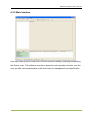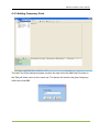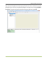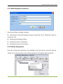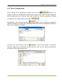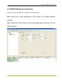
1
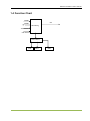
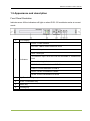
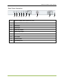
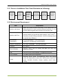
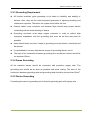
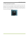
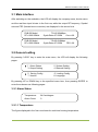
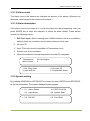
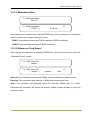
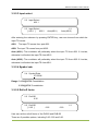
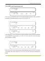
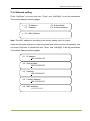
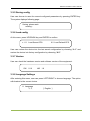
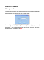
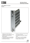
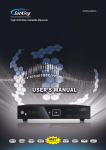
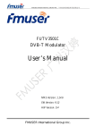
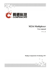
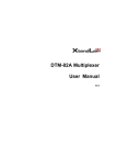
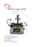
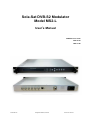
Sola-Sat DVB-S2 Modulator Model MS2-L User’s Manual NMS Version: V4.01 SW: V0.16 HW: V1.90 Sola-Sat Inc Pompano Beach, Florida www.sola-sat.net TABLE OF CONTENTS CHAPTER 1 PRODUCT OUTLINE ................................................................................. 1 1.1 OUTLINE............................................................................................................. 1 1.2 FEATURES ......................................................................................................... 1 1.3 SPECIFICATIONS .............................................................................................. 2 1.4 FUNCTION CHART ............................................................................................ 3 1.5 APPEARANCE AND DESCRIPTION ................................................................. 4 CHAPTER 2 INSTALLATION GUIDE ............................................................................. 6 2.1 ACQUISITION CHECK ....................................................................................... 6 2.2 INSTALLATION PREPARATION ....................................................................... 6 2.3 ELECTRICAL CABLE CONNECTION ............................................................... 9 2.4 SIGNAL CABLE CONNECTION ........................................................................ 9 CHAPTER 3 OPERATION ............................................................................................ 11 3.1 MAIN INTERFACE ............................................................................................ 12 3.2 GENERAL SETTINGS ...................................................................................... 12 CHAPTER 4 NMS SETTINGS ...................................................................................... 23 4.1 INSTALLATION ................................................................................................ 23 4.2 SOFTWARE OPERATION................................................................................ 24 4.3 DVB-S2 MODULATOR OPERATION ............................................................... 31 CHAPTER 5 TROUBLE SHOOTING ............................................................................ 35 CHAPTER 6 PACKING LIST ........................................................................................ 36 Sola-Sat Inc Pompano Beach, Florida www.sola-sat.net DVB-S2 Modulator User’s Manual Chapter 1 product outline 1.1 Outline The DVB-S2 modulator is a high performance modulator developed according to DVB-S2 (EN302307) standard which is the standard of second generation of the European broadband satellite telecommunication. It adopts advanced framing structure, channel coding and modulation technology, increasing over 50% transmission ability more than DVB-S modulator under the same transmission condition and also providing a more powerful receiving ability in the same spectral efficiency. In addition, it is backwards-compatible with DVB-S (EN300421) modulating standard. This DVB-S2 modulator supports local and remote control through NMS software. The DVB-S2 modulator can be used for Broadcasting, Interactive Services, News Gathering and other Broadband satellite applications. 1.2 Features Fully compliant with DVB-S2(EN302307) standard Backwards-compatible with DVB-S (EN300421) modulating standard Two ASI inputs supporting hot backup Supporting local and remote control Output level attenuation 10MHz outer reference clock input Output frequency range: 950~2150MHz Full-size front panel LCD display and keyboard www.sola-sat.net DVB-S2 Modulator User’s Manual 1.3 Specifications Supporting both packet and byte mode TS input Supporting 188/204Byte transmission stream packet MPEG-TS Input Two ASI inputs, supporting hot backup ASI input connector: BNC, impedance 75Ω Frequency is continuously adjustable from 950 to 2150MHz Output Level attenuation is continuously adjustable from 0 to 31.5 dB; in step of 0.5 dB. RF Output Maximum Output level: 0dBm MER≥32dB Connector: N type, impedance 50Ω DVB-S DVB-S2 RS coding BCH coding Inner coding Convolutional LDPC coding Code Rate 1/2,2/3,3/4,5/6,7/8 1/2,3/5,2/3,3/4,4/5,5/6,8/9, 9/10 Constellation QPSK QPSK,8PSK Roll-off Factor 0.2, 0.25, 0.35 0.2, 0.25, 0.35 Symbol Rate 1-45MBauds Dimension 44mm×482mm×410mm Environmental 0~45℃(operation), -20~80℃ (storage) Power 100-240VAC±10%,50Hz-60Hz Outer coding Channel coding and modulation Miscellaneous 1-30M@8PSK; 1-45 M@QPSK www.sola-sat.net DVB-S2 Modulator User’s Manual 1.4 Function Chart 10MHz RF 10MHz Modulating ASI interface ASI interface CPU control LCD KEY RJ45 www.sola-sat.net DVB-S2 Modulator User’s Manual 1.5 Appearance and description Front Panel Illustration Indicator area: All the indicators will light on when DVB –S2 modulator works at current mode. 1. LCD display Power : Power Indicator Ext 10M : 10MHZ Outer Reference Clock ASI1 : ASI1 input ASI2 : ASI2 input 2. Indicators TS Overflow: Input TS bit rate over the bandwidth of Transmission Limit Alarm : Alarming Indicator DVB-S2: Current Modulation is DVB-S2 DVB-S: Current Modulation is DVB-S 8PSK: Current constellation is 8PSK QPSK: Current constellation is QPSK 3. Up/Down/Left /Right key 4. Enter: Confirmation key 5. Menu key 6. Locking key www.sola-sat.net DVB-S2 Modulator User’s Manual Rear Panel Illustration 1 2 3 4 5 6 7 1. Input of 10Mhz Outer Reference Clock 2. Output of 10Mhz Inner Reference Clock 3. ASI1Input 4. ASI2 Input 5. ASI1Loop Output 6. ASI2 Loop Output 7. Network Interface 8. RF Output 9. Power Socket 10. Grounding pole 8 9 10 www.sola-sat.net DVB-S2 Modulator User’s Manual Chapter 2 Installation Guide 2.1 Acquisition Check When user opens the package of the device, it is necessary to check items according to packing list. Normally it should include the following items: DVB-S2 modulator User’s Manual ASI Cable Power Cord If any item is missing or mismatching with the list above, please contact local dealer. 2.2 Installation Preparation When users install device, please follow the below steps. The details of installation will be described at the rest part of this chapter. Users can also refer rear panel chart during the installation. The main content of this chapter including: Checking the possible device missing or damage during the transportation Preparing relevant environment for installation Installing modulator Connecting signal cables Connecting communication port (if it is necessary) www.sola-sat.net DVB-S2 Modulator User’s Manual 2.2.1 Device’s Installation Flow Chart Illustrated as following: Acquisition Check Fixing Device Connecting Grouding Wire and Power Cord Connecting Signal Wire Setting Parameter Running Device 2.2.2 Environment Requirement Item Machine Hall Space Requirement When user installs machine frame array in one machine hall, the distance between 2 rows of machine frames should be 1.2~1.5m and the distance against wall should be no less than 0.8m. Electric Isolation, Dust Free Machine Hall Floor Volume resistivity of ground anti-static material: 1X10⁷~1X10¹⁰, Grounding current limiting resistance: 1M (Floor bearing should be greater than 450Kg/㎡) Environment Temperature 5~40℃(sustainable ),0~45℃(short time), Relative Temperature 20%~80% sustainable 10%~90% short time Pressure 86~105KPa Door & Window Installing rubber strip for sealing door-gaps and dual level glasses for window Wall It can be covered with wallpaper, or brightness less paint. Fire Protection Fire alarm system and extinguisher Power Requiring device power, air-conditioning power and lighting power are independent to each other. Device power requires AC power 100-240V 50-60Hz. Please carefully check before running. installing air-conditioning is recommended www.sola-sat.net DVB-S2 Modulator User’s Manual 2.2.3 Grounding Requirement All function modules’ good grounding is the basis of reliability and stability of devices. Also, they are the most important guarantee of lightning arresting and interference rejection. Therefore, the system must follow this rule. Coaxial cable’s outer conductor and isolation layer should keep proper electric conducting with the metal housing of device. Grounding conductor must adopt copper conductor in order to reduce high frequency impedance, and the grounding wire must be as thick and short as possible. Users should make sure the 2 ends of grounding wire well electric conducted and be antirust. It is prohibited to use any other device as part of grounding electric circuit The area of the conduction between grounding wire and device’s frame should be no less than 25mm2. 2.2.4 Frame Grounding All the machine frames should be connected with protective copper strip. The grounding wire should be as short as possible and avoid circling. The area of the conduction between grounding wire and grounding strip should be no less than 25mm 2. 2.2.5 Device Grounding Connecting the device’s grounding rod to frame’s grounding pole with copper wire. www.sola-sat.net DVB-S2 Modulator User’s Manual 2.3 Electrical Cable Connection The grounding wire conductive screw is located at the right end of rear panel, and the power switch, fuse, power supply socket is just beside ,whose order goes like this, power switch is on the left ,power supply socket is on the right and the fuse is just between them. Connecting Power Cord User can insert one end into power supply socket, while insert the other end to AC power. Connecting Grounding Wire When the device solely connects to protective ground, it should adopt independent way, say, share the same ground with other devices. When the device adopts united way, the grounding resistance should be smaller than 1Ω. Caution: Before connecting power cord to DVB-S2 modulator, user should set the power switch to “OFF”. 2.4 Signal Cable Connection The signal connections include the connection of input signal cable and the connection of output signal cable. The details are as follows: 2.4.1 ASI input and loop output cable illustration: www.sola-sat.net DVB-S2 Modulator User’s Manual 2.4.2 RF output interface connection User can firstly find the RF out interface on the device according to the connector mark described on the rear panel illustration, and then connect the coaxial cable (in the accessories). One end is connected to the modulator’s RF out connector while the other end to the power transmitter’s RF input. The modulator’s RF output interface and its connection are illustrated as follow: www.sola-sat.net DVB-S2 Modulator User’s Manual Chapter 3 Operation DVB-S2 modulator’s front panel is user operation interface. Before operating, user can decide whether directly use the default setting or customize the input and output parameters setting. The detail operations go as follows: Keyboard Function Description: MENU: Canceling presently entered value, resuming previous setting; Return to previous menu. ENTER: Activating the parameters which need modifications, or confirming the change after modification. LEFT/RIGHT: To choose and set the parameters. UP/DOWN: Modifying activated parameter or paging up/down when parameter is inactivated. LOCK: Lock the screen / cancel the lock state. After pressing lock key, the system will question the users to save present setting or not. If not, the LCD will display the current configuration state. At the “Resume Factory Setting” page, user can firstly press “ENTER” key, consequently system resumes factory parameter setting. www.sola-sat.net DVB-S2 Modulator User’s Manual 3.1 Main Interface After switching on the modulator, the LCD will display the company name, device name and the real-time input bit-rate in the first row, while the output RF frequency, Symbol rate and FEC (forward error correction) are displayed in the second row. DVB-S2 Modul RF=1000.00MHz TS=05.654Mbps Symb-Rate=27.500M Conv=3/4 DVB-S2 Modul RF=1000.00MHz TS=05.654Mbps Symb-Rate=27.500M FEC=3/4 3.2 General setting By pressing “LOCK” key to enter the main menu, the LCD will display the following pages: 1 Alarm Status 3 Output Setting 2 System Setting 4 Network Setting 5 Saving Config 7 Version 6 Loading Config 8 Language By pressing UP or DOWN key to the specified menu item, then pressing ENTER to enter the submenu as following pages: 3.2.1 Alarm Status Temperature: Alarm Count: 34 Centidegree 0 3.2.1.1 Temperature The figure displayed in the first row shows the real-time housing temperature. www.sola-sat.net DVB-S2 Modulator User’s Manual 3.2.1.2 Alarm count The Alarm count in the second row indicates the amount of the alarms. Whenever an abnormal event happens, the number will increase 1. 3.2.1.3 Alarm description If the alarm count is not equal to 0, it must be at least one alarm happening. User can press ENTER key to enter the submenu to check the alarm details. These alarms include the following events: 1. Ref Clock Lose: When choosing outer 10MHz reference clock as modulator’s working clock, the modulator cannot detect reference clock input. 2. No input TS 3. Input TS bit rate over the bandwidth of Transmission Limit 4. Internal error of the modulator 5. When the modulator’s house temperature exceeds 70 centigrade. Temperature: Alarm Count: 34 Centidegree 4 1. Ref Clock Lose 4. Internal Error 2. No input TS 5. Temperature Alarm 3.2.2 System setting By pressing UP/DOWN or LEFT/RIGHT to choose this item, ENTER and LEFT/RIGHT to set the parameters. The system displays following pages: ▶ 2.1 Alarm Status 2.3 Input Select 2.2 REF Clock Sel 2.4 Symbol Rate ▶ 2.5 Roll Off 2.6 Conv Rate www.sola-sat.net DVB-S2 Modulator User’s Manual 3.2.2.1 Modulation State 2.1 Modulate Mode DVB_S 2.1 Modulate Mode [ DVB_S ] 1/1 DVB_S2 After entering the submenu by pressing ENTER key, user can choose the “modulation state” to choose the needed modulation mode. DVB-S: this modulator works as DVB-S modulator (QPSK modulator). DVB-S2: this modulator works as DVB-S2 modulator. 3.2.2.2 Reference Clock Select After entering the submenu by pressing ENTER key, user can choose from which the “Reference Clock” comes. 2.2 REF Clock Sel internal 2.2 REF Clock Sel [ internal ] 1/1 external auto Internal: This modulator uses internal 10MHz crystal oscillator as reference clock. External: This modulator uses external 10 MHz input as reference clock. Auto: The modulator will preferably select the external 10MHz input if it exists. Otherwise the modulator will select the internal 10MHz crystal oscillator’s output as reference clock. www.sola-sat.net DVB-S2 Modulator User’s Manual 3.2.2.3 Input select 2.3 Input Select ASI 1 2.3 Input Select [ ASI 1 ] ASI 2 1/1 Auto(ASI 2) Auto(ASI 1) After entering the submenu by pressing ENTER key, user can choose from which the input TS comes. ASI1: The input TS comes from port ASI1. ASI2: The input TS comes from port ASI2. Auto (ASI1): The modulator will preferably select the input TS from ASI1 if it exists; otherwise it will select the input TS from ASI 2. Auto (ASI2): The modulator will preferably select the input TS from ASI2 if it exists; otherwise it will select the input TS from ASI 1. 3.2.2.4 Symbol rate 2.4 Symbol Rate 27.500M Range: 0-45M@QPSK Constellation 0-30M@8PSK Constellation 3.2.2.5 Roll-off factor 2.5 Roll Off 0.35 2.5 Roll Off [ 0.35 ] 1/1 0.25 0.20 User can set the roll-off factor of the DVB-S and DVB-S2 There are 3 possible options, including 0.35, 0.25 and 0.20. www.sola-sat.net DVB-S2 Modulator User’s Manual 3.2.2.6 FEC rate/Convolutional rate 2.6 Conv Rate 3/4 2.6 Conv Rate 1/2 2/3 1/1 [ 3/4 ] 5/6 7/8 User can set convolutional value at this submenu when modulator works as DVB-S modulator. The possible options include 1/2, 2/3, 3/4, 5/6, 7/8. 2.6 FEC Rate 1/2 2.6 FEC Rate [ 1/2 ] 3/5 2/3 3/4 4/5 2.6 FEC Rate [ 8/9 ] 9/10 1/2 5/6 1/2 User can set FEC value at this submenu when modulator works as DVB-S2 modulator. The possible FEC rates include 1/4, 1/3, 2/5, 1/2, 3/5, 2/3, 3/4, 4/5, 5/6, 8/9, 9/10 when the constellation is QPSK. 2.6 FEC Rate 3/5 2.6 FEC Rate [ 3/5 ] 2/3 3/4 5/6 8/9 1/1 9/10 User can set FEC value at this submenu when modulator works as DVB-S2 modulator. The possible FEC rates include 3/5, 2/3, 3/4, 5/6, 8/9, 9/10 when the constellation is 8PSK. www.sola-sat.net DVB-S2 Modulator User’s Manual 3.2.2.7 Constellation (This menu item only shows when MODUALTO STATE is DVB-S2) 2.7 Constellation QPSK 2.7 Constellation [ QPSK ] 1/1 8PSK User can choose the DVB-S2 modulation’s constellation, either QPSK or 8PSK. 3.2.2.8 Pilot Insert (This menu item only shows when MODUALTO STATE is DVB-S2) 2.8 Pilot Insert Off 2.8 Pilot Insert [ Off ] 1/1 On User can choose whether to insert the Pilot block. Off: without pilots On: with pilots www.sola-sat.net DVB-S2 Modulator User’s Manual 3.2.3 Output setting Pressing UP/DOWN or LEFT/RIGHT to choose this item, ENTER and LEFT/RIGHT to set the parameters. The system displays following page: ▶ 3.1 Frequency 3.3 Spec Invert 3.2 Attenuation 3.4 RF Output 3.2.3.1 RF setting After entering the submenu by pressing ENTER key, user can set RF output frequency. The RF output frequency range is from 950 to 2150MHz. 3.1 Frequency 1000.00MHz 3.2.3.2 RF ATT Setting User can set the attenuation of the RF output at this submenu. The RF attenuation range is from 0-31.5db in 0.5db step. 3.2 Attenuation 30.5 db 3.2.3.3 Spectrum Invert User can set the Spectrum of RF output invert or not. 3.3 Spec Invert normal 3.3 Spec Invert [ normal ] 1/1 invert www.sola-sat.net DVB-S2 Modulator User’s Manual 3.2.3.4 RF Output 3.4 RF Output single tone 3.4 RF Output [ single tone ] modulation 1/1 off User can set the RF output mode for different applications. Single tone: the RF output is only carrier without modulation. Modulation: The RF output carrier with modulation. www.sola-sat.net DVB-S2 Modulator User’s Manual Off: Turn off the RF output. www.sola-sat.net DVB-S2 Modulator User’s Manual 3.2.4 Network setting Press “Up/Down” to choose this item. “Enter” and “Left/Right” to set the parameters. The system displays following pages. ▶ 4.1 IP Address 4.3 Gateway 4.2 Subnet Mask 4.4 Console Address ▶ 4.5 MAC Address Note: The MAC address is according to the factory setting, and it’s unique. Under the following submenus, there are parameters which can be set manually; user can press “Up/Down” to choose this item. “Enter” and “Left/Right” to set the parameters. The system displays following pages. 4.1 IP Address 192.168.000.136 4.2 Subnet Mask 255.255.255.000 4.3 Gateway 192.168.000.001 4.4 Console Address 192.168.000.221 4.5 MAC Address ffffffffffff www.sola-sat.net DVB-S2 Modulator User’s Manual 3.2.5 Saving config User can choose to save the current configured parameters by pressing ENTER key. The system displays following page: Saving, please wait: erasing... 3.2.6 Load config At this menu, press UP/DWON key and ENTER to confirm. ▶ 6.1 Load Saved CFG 6.2 Load Default CFG User can restore the device into the last saved configuration by choosing “6.1” and restore the device into factory configuration by choosing “6.2”. 3.2.7 Version User can check the hardware version and software version of the equipment. SW 0.16 HW 1.9 3.2.8 Language Settings After entering this menu, user can press LEFT/RIGHT to choose language. The option with bracket is the current choice. 8 Language 中文 [ English ] www.sola-sat.net DVB-S2 Modulator User’s Manual Chapter 4 NMS Setting Network Management System Profile Network management system is applied to digital TV equipment operation, control and management and parameters setting, etc. It centralizes digital TV equipment through network. 4.1 Installation The software doesn’t need special installation. User can just copy “Network Management Software X.XXY.exe” to the specified directory (X.XX is version number, Y represents language. For example: the version number of network management software 4.01E.exe is 4.01 English version) or place different versions of network management software to the same directory. When the network management software is running, it will generate two documents as follows: Network management software X.XXY.log (It preserves the log file.) Info. Bin (It’s the user configuration data.) www.sola-sat.net DVB-S2 Modulator User’s Manual 4.2 Software Operation 4.2.1 Login Interface A login interface will pop up firstly when the software is running and give user prompts to input user name and password, the menu shows as follows: User can login the NMS by pressing Confirm key after inputting user name and password. Upon the inputs, the software will verify them with database record automatically. If both of them are correct, the main interface will appear. Both of the default user name and password are admin. www.sola-sat.net DVB-S2 Modulator User’s Manual 4.2.2 Main Interface User can create a device node tree in the left column by adding, modifying and deleting the device node. This software provides a powerful node operation function, and the user can edit various parameters in the device tree for management and classification. www.sola-sat.net DVB-S2 Modulator User’s Manual 4.2.3 Adding Frequency Point The Add Freq Point dialog box popes up when the user clicks the Add Freq Point item in the Edit pull down menu on the menu row. The device will confirm the given frequency while user clicks OK. www.sola-sat.net DVB-S2 Modulator User’s Manual User can also click right mouse key to pop up the short-cut menu in device tree or in the left blank column, then the corresponding dialog box will pop up by choosing Add Main Freq Point. The device will confirm the given frequency while user clicks OK. www.sola-sat.net DVB-S2 Modulator User’s Manual 4.2.4 Adding Equipment under Given Frequency Point User should choose the frequency point in advance, and then the dialog box of Add Equipment will pop up when user clicks “Add Equipment” item in the Edit pull down menu on the menu row. www.sola-sat.net DVB-S2 Modulator User’s Manual 4.2.5 Edit Equipment Interface User should follow the steps as below: Choosing the connected equipment type in drop down list of “Equipment Type” by clicking the “▼”. Inputting the Equipment Name Inputting the device IP Address Inputting the device Port Number 4.2.6 Delete Equipment User can choose the equipment to be deleted in the left column, and then click the “delete” item in the pull down menu which appears by clicking the right mouse key. www.sola-sat.net DVB-S2 Modulator User’s Manual 4.2.7 Save Configuration After finishing all the parameters setting, user can click button on the toolbar to save the modifications to the device’s flash, while user can also reload the saved parameters from device’s flash and refresh the device’s parameters setting according to the loaded values by clicking Alternatively, user can also click the button on the toolbar to popup the “save file” dialog box, which gives prompts to save all the device’s parameters as binary files in the computer’s hard disk. Similarly, user can choose to click the button on the toolbar to popup the read file dialog box, to read the stored binary file and set the device’s parameters according to the loaded binary files. www.sola-sat.net DVB-S2 Modulator User’s Manual 4.3 DVB-S2 Modulator Operation User can choose the DVB-S2 modulator in the device tree. Set: making the current parameters, which show in the NMS software, activate. Get: reading the current device’s activating parameters and show them on NMS software. www.sola-sat.net DVB-S2 Modulator User’s Manual 4.3.1 Modulation Mode User can select the modulator’s working mode and relevant constellation at this drop-down list. DVB-S: This modulator works as DVB-S modulator (QPSK modulator) DVB-S2 QPSK: This modulator works as DVB-S2 modulator with QPSK constellation. DVB-S2 8PSK: This modulator works as DVB-S2 modulator with 8PSK constellation. www.sola-sat.net DVB-S2 Modulator User’s Manual 4.3.2 Reference Clock Internal: This modulator uses internal 10MHz crystal oscillator as reference clock. External: This modulator uses external 10 MHz input as reference clock. Auto: The modulator will preferably select the external 10MHz input if it exists. Otherwise the modulator will select the internal 10MHz crystal oscillator’s output as reference clock. 4.3.3 Input Select ASI1: The input TS comes from port ASI1. ASI2: The input TS comes from port ASI2. Auto (ASI1): The modulator will preferably select the input TS from ASI1 if it exists; otherwise it will select the input TS from ASI 2. Auto (ASI2): The modulator will preferably select the input TS from ASI2 if it exists; otherwise it will select the input TS from ASI 1. 4.3.4 Roll off factor User can set the roll-off factor of the DVB-S and DVB-S2 There are 3 possible options, including 0.35, 0.25 and 0.20. 4.2.5 Conv Rate This option only activate when the modulation mode is DVB-S, in other words, this modulator works as DVB-S modulator. The possible convolutional options include 1/2, 2/3, 3/4, 5/6, 7/8. 4.2.6 FEC Code Rate User can set FEC value at this menu when modulator works as DVB-S2 modulator. The possible FEC rates include 1/4, 1/3, 2/5, 1/2, 3/5, 2/3, 3/4, 4/5, 5/6, 8/9, 9/10 when the constellation is QPSK. www.sola-sat.net DVB-S2 Modulator User’s Manual 4.2.7 Pilot Insert User can choose whether to insert the Pilot block in the check box. 4.2.8 Symbol Rate Range: 0~45M@QPSK Constellation 0~30M@8PSK Constellation 4.2.9 RF ATT User can set the attenuation of the RF output. The RF attenuation range is from 0-31.5db in 0.5db step. 4.2.10 Modulation On Optional: User can set the RF output mode for different applications. Single tone: the RF output is only carrier without modulation. Modulation: The RF output carrier with modulation. Off: Turn off the RF output. 4.2.11 RF User can set RF output frequency. The RF output frequency range is from 950 to 2150MHz. www.sola-sat.net DVB-S2 Modulator User’s Manual Chapter 5 Troubleshooting The supplier’s ISO9001 quality assurance system has been approved by CQC organization. For guarantee the products’ quality, reliability and stability. All products have been passed the testing and inspection before ship out factory. The testing and inspection scheme already covers all the Optical, Electronic and Mechanical criteria which have been published by the supplier. To prevent potential hazard, please strictly follow the operation conditions. Preventive Measures Installing the device at the place in which environment temperature between 0 to 45 °C Making sure good ventilation for the heat-sink on the rear panel and other heat-sink bores if necessary Checking the input AC voltage within the power supply working range and the connection is correct before switching on device Checking the RF output level varies within tolerant range if it is necessary Checking all signal cables have been properly connected Frequently switching on/off device is prohibited; the interval between every switching on/off must greater than 10 seconds. Conditions need to unplug power cord Power cord or socket damaged. Any liquid spilled onto device. Any cause of a short circuit Device in damp environment physical damage to the device Prolonged idle period. After switching on and restoring to factory setting, device still not working properly. www.sola-sat.net DVB-S2 Modulator User’s Manual Chapter 6 Packing List DVB-S2 modulator 1pcs User’s manual 1pcs Power cord 1pcs ASI Cable 1pcs www.sola-sat.net