1
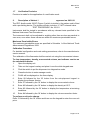
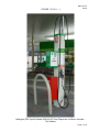
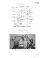
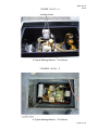
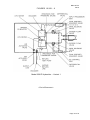
NMI 10/1/21
Rev 6
Certificate of Approval
No 10/1/21
Issued by the Chief Metrologist under Regulation 60
of the
National Measurement Regulations 1999
This is to certify that an approval for use for trade has been granted in respect of
the instruments herein described.
Gallagher Model 3261N LPG Fuel Dispenser for Motor Vehicles
submitted by
Gallagher Fuel Systems Ltd
2 Station Road
Marton
4741
New Zealand
NOTE: This Certificate relates to the suitability of the pattern of the instrument for
use for trade only in respect of its metrological characteristics. This Certificate
does not constitute or imply any guarantee of compliance by the manufacturer or
any other person with any requirements regarding safety.
This approval has been granted with reference to document NMI R 117 Measuring
Systems for Liquids Other than Water, dated June 2011.
This approval becomes subject to review on 1/12/19, and then every
5 years thereafter.
DOCUMENT HISTORY
Rev
0
1
2
3
4
5
6
Reason/Details
Pattern & variant 1 approved – interim certificate issued
Pattern & variant 1 approved – certificate issued
Variant 2 approved – interim certificate issued
Variant 2 approved – certificate issued
Pattern & variants 1 & 2 reviewed– notification of change
issued
Pattern & variants 1 & 2 amended, reviewed & updated –
certificate issued
Test Procedure amended (procedure to view temperature, etc.)
– certificate issued
Date
28/11/01
8/03/02
18/10/06
23/03/07
11/02/08
13/02/14
12/08/15
Page 1 of 10
NMI 10/1/21
Rev 6
CONDITIONS OF APPROVAL
General
Instruments purporting to comply with this approval shall be marked with pattern
approval number ‘NMI (or NSC) 10/1/21’ and only by persons authorised by the
submittor.
It is the submittor’s responsibility to ensure that all instruments marked with this
approval number are constructed as described in the documentation lodged with
the National Measurement Institute (NMI) and with the relevant Certificate of
Approval and Technical Schedule. Failure to comply with this Condition may
attract penalties under Section 19B of the National Measurement Act and may
result in cancellation or withdrawal of the approval, in accordance with document
NMI P 106.
Auxiliary devices used with this instrument shall comply with the requirements of
General Supplementary Certificates No S1/0/A or No S1/0B.
Signed by a person authorised by the Chief Metrologist
to exercise their powers under Regulation 60 of the
National Measurement Regulations 1999.
Dr A Rawlinson
Page 2 of 10
NMI 10/1/21
Rev 6
TECHNICAL SCHEDULE No 10/1/21
1.
Description of Pattern
approved on 28/11/01
A Gallagher model 3261N LPG fuel dispenser (Figures 1 and 2) for refuelling
motor vehicles using liquefied petroleum gas (LPG). The dispenser is approved
for use) in attendant-operated mode, or in self-service mode when interfaced to a
compatible (#) approved self-service device. May also be known as PEC Apollo
instruments of the same models.
(#)
‘Compatible’ is defined to mean that no additions/changes to
hardware/software are required for satisfactory operation of the complete
system.
1.1
Field of Operation
The following specifies the field of operation for which the metering system is
approved:
•
•
•
•
•
•
•
Minimum measured quantity, Vmin
2L
Maximum flow rate, Qmax
60 L/min
Minimum flow rate, Qmin
10 L/min
LPG density range (at 15°C)
505 kg/m³ to 570 kg/m³
Volume conversion to 15°C over a liquid
temperature range of
-10°C to 40°C
Maximum operating pressure, Pmax
2450 kPa
Operating pressure is maintained at least 200 kPa above the
equilibrium vapour pressure of LPG
Ambient temperature range of
-25°C to 55°C
Accuracy Class
1.0
1.2
LPG Metering System
•
•
The model 3261N LPG dispenser (Figures 1 and 2) includes the following
components or features:
•
•
•
•
A Batchen model Mk-V constant bleed vapour elimination device.
Two Batchen model Mk III LPG liquefied petroleum gas (LPG) flowmeters
each fitted with a PEC model 07439 pulse generator.
Two Batchen model Mk VI spring-loaded pressure differential valves.
A calculator/indicator configured for use with a density detection device
enabling the volume conversion to 15°C.
(i)
An LPG supply tank may be located either above or below the ground level.
(ii)
The pump is positioned either below the supply tank in which case the
pump is designed for use in a state of flooded suction, or the pump is
positioned above the supply tank in which case the pump shall be a
multistage regenerative turbine LPG pump designed for use in suction lift.
There shall be no restrictive fittings within ten pipe diameters of the pump
inlet and the diameter of the inlet pipe is not less than the diameter of the
pump inlet. The external pump by-pass relief valve is installed in a line
returning to the vapour space of the supply tank. A single pump supplying
LPG to several flowmeters shall be of sufficient capacity rating to ensure
that when all flowmeters are in use, the flow rate through each flowmeter is
greater than Qmin.
Page 3 of 10
NMI 10/1/21
Rev 6
(iii)
A Batchen model Mk-V constant bleed vapour eliminator with an integral
strainer positioned upstream of the flowmeter, in conjunction with a
pressure differential valve downstream of each flowmeter (Figure 2), protect
the flowmeters from the measurement of vapour. The thermometer well for
checking the temperature measurement is situated at the top of the vapour
eliminator.
(iv)
Two Batchen model Mk III two-piston LPG flowmeters are used (Figure 3)
each fitted with a PEC model 07439 pulse generator producing 100 pulses
per channel (×2 channels) per meter revolution.
(v)
A Batchen model Mk VI spring-loaded pressure differential valve (Figures 2
and 3) is fitted to the outlet. A pressure-equalising pipe is connected from
the top of the differential valve to the vapour space of the supply tank. The
pressure differential valve is fitted with a bleed valve and a ¼”NPT
extension union which gives provision for a pressure gauge. Any bleed
valves in normal operation are sealed with to prevent leakage.
(vi)
A Batchen hydraulic accumulator may be fitted downstream of the pressure
differential valve.
(vii)
A ½” NPT solenoid valve is located downstream of the pressure differential
valve. The valve controls the delivery and prevents delivery during the reset
cycle.
(viii)
The dispenser is fitted with hoses of 15 or 20 mm nominal bore and
incorporates Batchen Sentry 20 hose break-away couplings, fitted between
the flow solenoid valves and the nozzles.
(ix)
Gasguard model LG1DNS nozzles or any other NMI-approved compatible
(#) LPG nozzles (*) may be used that are suitable for the Gallagher/PEC
nozzle hang-up mechanism.
(*)
Note that the submittor must be consulted regarding the acceptability of any
alternative nozzles.
(x)
A recirculation line with a double check filler valve is provided at the
dispenser for returning the LPG back to the supply tank. The recirculation
line is used for maintenance checking or calibration of the dispenser.
(xi)
The calculator/ indicator comprises a PEC model MHP indicator-computing
unit and a display unit. A separate display is provided for volume, total
price, and unit price. The indicators display the following maximum values:
Volume 999.99 L
Unit price 999.9 c/L
Total price $999.99
Totaliser 9999999
The calculator/indicator can display LPG density at 15°C used for
conversion of volume to 15°C, and can display the temperature of LPG
flowing through the meter (refer Test Procedure).
The software version numbers for the calculator/indicator are VA 3.06P (for
the main processor) and VI 3.05S (for the input processor). These version
numbers may be viewed using the set-up keypad (refer to the Test
Procedure).
(#)
‘Compatible’ is defined to mean that no additions/changes to
hardware/software are required for satisfactory operation of the complete
system.
Page 4 of 10
NMI 10/1/21
Rev 6
1.3
Operation
Removal of the nozzle from its receptacle starts the operating cycle. The display
will be cleared of any previous sale and the remote pump will start. The systems
electronics will automatically check for pulser rotation and correct electronic
parameters.
A segment check is initiated; when completed, the unit price is displayed, and the
price and volume displays show zeroes. At the end of this cycle the solenoid valve
opens allowing a delivery. Replacing the nozzle to its normal hang up position
closes the solenoid valve. The delivery details are displayed until the next reset
cycle.
1.4
Volume Conversion Device
The electronic volume conversion for temperature facility is used to convert the
measured volume to volume at 15°C using the volume conversion factors as a
function of density in accordance with Table 54 of the ASTM-IP-API Petroleum
Measurement Tables for Light Hydrocarbon Liquids.
The calculator/indicator is configured for use with an LPG Measurement model
DSS*-98 (##) density detector probe to display the delivered volume at 15°C.
(##)
DSS*-98 where * may be either B or P.
1.5
Markings and Notices
Instruments are marked with the following data, together in one location on a data
plate:
Pattern approval number
NMI No 10/1/21
Manufacturer’s identification mark or trade mark
.....
Manufacturer’s designation (model number)
.....
Serial number
.....
Year of manufacture
.....
Environmental class
class N
Maximum flow rate (Qmax)
..... L/min
Minimum flow rate (Qmin)
..... L/min
1800 kPa
Maximum operating pressure (Pmax)
Minimum pressure (Pmin)
200 kPa above vapour pressure
Approved for LPG density range
505 kg/m³ to 570 kg/m³ (at 15°C)
Maximum liquid temperature (Tmax)
50°C
Minimum liquid temperature (Tmin)
–10°C
Accuracy class
class 1.0
Note: The minimum measured quantity (Vmin) shall be clearly visible on any
indicating device visible to the user during measurement, in the form
‘Minimum Delivery 2 L’.
Volume indicated for LPG shall be clearly identified as ‘Litres at 15°C’ or
similar wording.
1.6
Sealing Provision
A plate covering the calibration switch situated inside the calculator/indicator, and
the mechanical calibration device on the flowmeter, have provision for sealing.
(Figures 4 & 5).
The flowmeter bleed valve has provision for sealing.
Page 5 of 10
NMI 10/1/21
Rev 6
1.7
Verification Provision
Provision is made for the application of a verification mark.
2.
Description of Variant 1
approved on 28/11/01
The PEC Apollo model 3261P (Figure 6) which is similar to the pattern and is fitted
with a pre-setting device. The system will also include a ¼” NPT solenoid valve.
TEST PROCEDURE No 10/1/21
Instruments shall be tested in accordance with any relevant tests specified in the
National Instrument Test Procedures.
The instrument shall not be adjusted to anything other than as close as practical to
zero error, even when these values are within the maximum permissible errors.
Maximum Permissible Errors
The maximum permissible errors are specified in Schedule 1 of the National Trade
Measurement Regulations 2009.
Calibration Procedure
For detailed configuration and code setting procedures, refer to the manufacturer’s
service manual.
The calibration of the flowmeter shall be carried out using the unconverted volume.
To view temperature, density, unconverted volume, and software version on
the calculator/indicator
1.
Open the display unit.
2.
Take out the keypad overlay and place it over the white keypad area.
3.
Flick the switch to put the dispenser into diagnostics mode.
4.
Press the button to enter manager mode.
5.
FN-00 will be displayed on the litres display.
6.
Enter 08 followed by the ‘fill’ button from the set-up/pre-set keypad to
display the software version.
7.
Enter 37 followed by the ‘fill’ button to display the unconverted volume.
8.
Enter 82 followed by the ‘fill’ button to display the density at 15°C.
9.
Enter 83 followed by the ‘fill’ button to display the temperature at metering
conditions.
10.
Enter 84 followed by the ‘fill’ button to display the volume correction factor.
To perform a unit price change
Enter 31 followed by the ‘fill’ button and then use the keypad to enter the new unit
price.
Page 6 of 10
NMI 10/1/21
Rev 6
FIGURE 10/1/21 – 1
Gallagher (PEC Apollo) Model 3261N LPG Fuel Dispenser for Motor Vehicles –
The Pattern
Page 7 of 10
NMI 10/1/21
Rev 6
FIGURE 10/1/21 – 2
Model 3261N LPG Hydraulics – The Pattern
FIGURE 10/1/21 – 3
Batchen Model Mk III LPG Meter and
Batchen Model Mk VI Pressure Differential Valve
Page 8 of 10
NMI 10/1/21
Rev 6
FIGURE 10/1/21 – 4
A Typical Sealing Method – The Pattern
FIGURES 10/1/21 – 5
A Typical Sealing Method – The Pattern
Page 9 of 10
NMI 10/1/21
Rev 6
FIGURES 10/1/21 – 6
Model 3261P Hydraulics – Variant 1
~ End of Document ~
Page 10 of 10