1
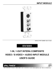
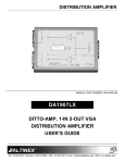
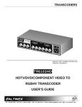
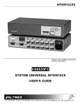
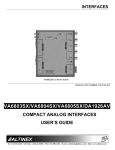
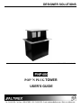
DESIGNER SOLUTIONS
MANUAL PART NUMBER: 400-0109-005
PNP400
POP 'N PLUG TOWER
USER'S GUIDE
DESIGNER SOLUTIONS
TABLE OF CONTENTS
Page
PRECAUTIONS / SAFETY WARNINGS .............. 3
ABOUT YOUR PNP400 ................................ ....... 4
TECHNICAL SPECIFICATIONS .......................... 4
PNP400 DIMENSIONS ................................ ........ 5
APPLICATION DIAGRAMS ................................ . 6
INSTALLATION ................................ ................... 8
OPERATION................................ ........................ 9
FREQUENTLY ASKED QUESTIONS (FAQ) ..... 10
CABLES AND ACCESSORIES.......................... 11
TROUBLESHOOTING GUIDE........................... 11
ALTINEX POLICY................................ .............. 11
DESIGNER SOLUTIONS
PRECAUTIONS / SAFETY WARNINGS
Please read this manual carefully before using your
PNP400 Interconnect Tabletop Solution. Keep this
manual handy for future reference. These safety
instructions are to ensure the long life of your
PNP400 and to prevent fire and shock hazard.
Please read them carefully and heed all warnings.
1.1 GENERAL
•
•
Unauthorized personnel shall not open the
unit since there are high-voltage components
inside.
Qualified ALTINEX service personnel, or their
authorized representatives must perform all
service.
1.2 INSTALLATION
•
•
•
•
•
•
•
•
cord that is attached to the PNP400
Interconnect Tabletop Solution.
1
For best results, place the PNP400
Interconnect Box in a dry area away from dust
and moisture, indoors only.
To prevent fire or shock, do not expose this
unit to rain or moisture. Do not place the
PNP400 Interconnect Tabletop Solution in
direct sunlight, near heaters or heat radiating
appliances, or near any liquid. Exposure to
direct sunlight, smoke, or steam can harm
internal components.
Handle the PNP400 Interconnect Tabletop
Solution carefully. Dropping or jarring can
damage internal components.
Be careful. Serious injury could result
because of the sharp edges inside of the
PNP400.
Do not place heavy objects on top of the
PNP400. Do not use excessive force to push
down on the top of the unit.
To turn off main power, disconnect the power
cord, which powers the power socket on the
PNP400 outlets.
We recommend using wall outlets with a
Ground Fault Circuit Interrupter (GFCI) for
maximum protection.
Install all cables according to the instructions.
Do not force or pull out any cable or power
1.3 CLEANING
•
Surfaces should be cleaned with a dry cloth.
Never use strong detergents or solvents, such
as alcohol or thinner. Do not use a wet cloth
or water to clean the unit.
DESIGNER SOLUTIONS
ABOUT YOUR PNP400
2
The PNP400 is designed for installation into a
conference room table. The PNP400 Interconnect
Tabletop Solution provides a means of connecting
A/V, network and power sources into a presentation
system. It is ideal for use together with ALTINEX
computer video interfaces, such as VA6804FC. The
PNP400 Interconnect Box can “pop up” into a
raised position to provide access to connectors or it
can be lowered into a table when not in use. The
PNP400 uses a tower-type construction with gas
spring suspension to accomplish this.
The PNP400 Interconnect Box has two openings
on either side of the unit, servicing both sides of a
table. Several optional sectional plates with
Computer Video (15-pin HD); Composite Video
(RCA), Audio (RCA), Computer Audio (Stereo
Mini), Modem (RJ-11), 9-pin D-type RS-232 and
Network (RJ-45) input connections can be used
with the PNP400. For additional information
regarding optional connectors, contact the
ALTINEX Sales Department.
The PNP400 Interconnect Box is designed for use
with tables ranging from one to three inches thick.
The PNP400 comes in a standard matte black
color. Custom finishes for the top of the PNP400
allow the unit to accent any table top. This is
available on a custom per order basis at an
additional charge.
TECHNICAL SPECIFICATIONS
MECHANICAL
Mechanical
Base Width (inches)
Height (opened)
Height Above Table
PNP400 (standard)
6.600in (167mm)
8.690in (220mm)
2.956in (75mm)
5.552in (141mm)
Height Below Table
(minus table thickness)
Base Depth (inches)
4.834in (122mm)
Finish
Black
T° Operating
10°C-35°C
T° Maximum
50°C
Humidity
90% non-condensing
Table 1. PNP400 Mechanical
3
DESIGNER SOLUTIONS
PNP400 DIMENSIONS
Diagrams: 1A, 1B, 1C, & 1D
4
DESIGNER SOLUTIONS
APPLICATION DIAGRAMS
5
Diagram 2: Application
Note: Diagram 2 is shown with special connector plates and cables installed. Connectors and cables are not
shipped with PNP400, they must be ordered separately. For more information regarding connectors and
cables designed for the PNP400, contact the ALTINEX Sales Department at (714) 990-2300 or visit the
ALTINEX website at www.altinex.com.
DESIGNER SOLUTIONS
Diagram 3: Table Cutout Requirements
Note: Specifications subject to change without notice. Measurements are NOT to scale. Always confirm
measurements before cutting to insure that specifications have not changed. Always make sure to
orient cutout in the direction necessary for proper operation of the installed unit.
DESIGNER SOLUTIONS
INSTALLATION
6
Step 1. The PNP400 ships with a shipping screw.
To remove the shipping screw, push down
and turn the spring retaining knob by 90
degrees. Then remove the knob from the
PNP400. The spring retaining knob is the
smallest silver colored knob that is located
in the center on the bottom of the unit.
Step 4. Secure the cables by using a cable clamp.
Pass the power cord from the bottom of
the housing and attach it to the table
using the cable clamp supplied with the
PNP400 unit. Do not keep the cord too
tight or too loose. (See Figure 2)
Re-engage the gas spring by pushing
down on the retaining knob and turning it
back to the original position, thereby
locking the gas spring into place.
Step 2. Cut an opening into the table’s surface
Refer to diagram 3 on page 6 of the
manual or the ALTINEX website at
www.altinex.com
for
table
cutout
requirements. Note: The table can be 3
inches or less in thickness. Always
confirm dimensions before cutting to
ensure that specifications have not
changed.
Step 3. Place the table support brackets under
the table and place them between the
grooves on the side of the PNP400 unit.
Place the brackets at the desired height
and secure them to the bottom of the
table using a setscrew. There are two
support brackets, one for each side of the
unit. (See Figure 1)
Figure 2: Cable Clamp Installation for Service
Loop (diagram above shows only the
power cord not the cables)
Step 5. Connect the appropriate cables with the
correct connectors of the media sources
(video, audio, etc.) being used on the
sectional plates.
Step 6. Once you have connected power and the
proper cables to the unit, you may raise
the unit. To raise the PNP400 into
position, press the top of the unit.
Step 7. To lower the unit, push on the top of the
PNP400 until it fits into place.
For more information, please refer to the FAQ
Section or the Troubleshooting Guide.
Figure 1:
Attachment of the PNP400 to the
table using support brackets and
set screws
DESIGNER SOLUTIONS
OPERATION
7
7.1 HOW TO RELEASE GAS SPRING
In order to remove and install the gas spring,
begin with the pop-up unit in the down position.
Apply some pressure in order to compress the
gas spring so it will not be ejected with force.
While the gas spring is compressed, remove the
side screws from the gas spring support bracket
on the bottom of the base unit.
7.3 HOW TO INSTALL GAS SPRING
Screw the replacement spring into the top of the
pop-up assembly. Do NOT over tighten. The spring
should be finger tightened only.
Attach the spring support bracket
compression rod portion of the spring.
to
the
Carefully compress the new spring while aligning
the support bracket mounting holes with those in
the base unit.
Fasten the compression rod using 4-40 hardware.
Under normal conditions the gas spring will last
more than five years.
Shock
Screws
In Here
Shock
Clearance
Hole
PNP400
Bottom
Top of
Shock
Remove
Screw
Remove
Screw
Figure 3: Spring Support Bracket
7.2 HOW TO REMOVE GAS SPRING
Unscrew the support bracket from the gas
spring.
On the bottom of the pop-up assembly, there is
a support bracket. This bracket has a clearance
hole the spring passes through.
Unscrew the gas spring from the top of the
pop-up assembly.
Remove the spring by sliding through the
clearance hole in the pop-up assembly support
bracket.
Figure 4: Removing the Gas Spring
DESIGNER SOLUTIONS
7.4 HOW TO INSTALL SECTIONAL PLATES
Install sectional plates in the empty slots on each
side of the PNP400 until the plates snap into place.
Secure the plates using the plastic reusable rivets
as shown in figure 5.
FREQUENTLY ASKED QUESTIONS (FAQ) 8
No:
1.
2.
3.
4.
What if my table
is thicker than 3
inches?
5.
Are cables
available for
connecting a
PC/laptop to the
PNP400
available?
Does ALTINEX
honor any
warranty on field
modifications?
Figure 5: Installing Sectional Plates
(Internal view of PNP400)
Question
What happens if
the spring
breaks?
What do I do if
the PNP400
won’t stay open?
How much room
is taken up on
the underside of
the table?
6.
Answer
The unit will not stay
open.
Replace the gas spring.
Call ALTINEX for service
information.
The unit is 5.5 inches
deep maximum below
the table; to this
dimension add about 2.5
inches for cable
clearance.
Then the area under the
table near the PNP400
must be reduced to 3
inches of thickness.
Consider using
MS8126CA (3ft) or
MS8156CA (6ft) for VGA
connection.
Anything modified by
non-ALTINEX personnel
is not covered by
warranty.
DESIGNER SOLUTIONS
CABLES AND ACCESSORIES
9
Model No.
Description
INPUT/OUTPUT LABELS
MS8301LB
Adhesive label with text
COVER CUTOUTS
CVR1001
Cover cutouts for PNP or TNP units
SECTIONAL PLATES
Dual AC Power Outlet for United States
SP2107US & Canada with 2 slots and 12ft metal
conduit
AC Power Outlet for United Kingdom,
SP2201UK
Singapore & Hong Kong
AC Power Outlet for Continental
SP2301CE
Europe
AC Power Outlet for Australia & New
SP2401AU
Zealand
SP3102EP Dual Empty Snap-in Ports with 1 slot
Dual Empty Ortronics CAT-6 Snap-in
SP3103EP
Ports with 1 slot
15-pin HD-Female to Male + 3.5mm
SP3201AV
Stereo Female to Male
15-pin HD-Female to Female Gender
SP3202AV Changer + 3.5mm Stereo Female to
Terminal Block
4-pin Mini DIN + RCA Female 3.5mm
SP3204AV Stereo with 1 slot (universal plate for
PNP400)
TROUBLESHOOTING GUIDE
10
The PNP400 supplied unit was carefully tested and
no problems were detected; however, we would like
to offer the following suggestions:
•
Please make sure that the highest quality video,
audio, network, and telephone cables or
connectors are used.
•
If there has been damage, then do not use the
PNP400 unit. Immediately contact the ALTINEX
Sales Department to have the unit repaired.
ALTINEX POLICY
11
11.1 LIMITED WARRANTY / RETURN POLICY
Please
see
the
Altinex
website
at
www.altinex.com for details on warranty and
return policy.
11.2 CONTACT INFORMATION
ALTINEX, INC
592 Apollo street
Brea, CA 92821 USA
TEL: 714 990-2300
TOLL FREE: 1-800-ALTINEX
WEB: www.altinex.com
E-MAIL: [email protected]