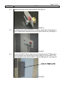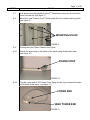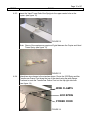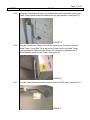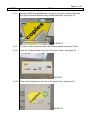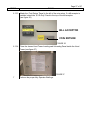
1
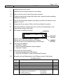
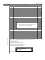
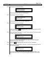
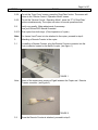
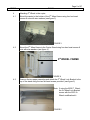
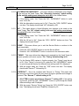
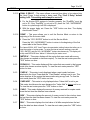
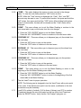
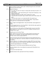
December 1, 2003
Page 1 of 27
Subject
US and Canada 2223 Konica Copier Installation Procedures
Applicability
All Konica 2223 Copiers using a Remote Counter
Or a Jamex 6552 or 6557 Vend Towers
SUMMARY
The following procedures are for installing a US or Canadian 2223 Konica
copier in an account that requires a Jamex Vend Tower.
This procedure includes the following:
1. Unpacking and set up of the copier
2. Programming the copier
3. Attaching a Remote Counter to the copier
4. Attaching the Vend Tower to the copier
5. Programming the Vend Tower
6. Placement of the decals on the copier
REQUIREMENTS
NOTES:
* These items are only used with the Jamex Vend Tower.
**These items are used only on Special Installation Options. Refer to the
MLA to determine if your account install is a Special Installation Option.
† Refer to the MLA to determine the Price Decal needed for your account.
Parts
Qty
1
1
1
1
1
1
1
2
2
1
Part Description
Konica 2223 Copier
Konica 2223 Copier Stand
*Jamex 6552 Vend Tower
** Jamex 6557 Vend Tower
*5th Wheel Assembly
*5TH Wheel Modification Kit
*Surge Protector
Riverside Brackets
Riverside Brackets Screws 3M x 16 Machine Screws
*Misc. Vend Tower Install Parts Kit
Part Number
K2223
39016
39017
39061
30215
CPD135
30225
30358
28140
Page 2 of 27
STEPS
REQUIREMENTS
Decals
TASKS
-continuedQty
Part Description
Part Number
1
1
1
1
1
1
1
1
1
1
1
1
1
1
1
1
1
Service / Supply Decal
** $1.00 Only Decal
*Change Return Decal
*Jamex Vend Tower Face Plate
† Price Decal $.05 Burst
† Price Decal $.07 Burst
† Price Decal $.10 Burst
† Price Decal $.15 Burst
† Price Decal $.25 Burst
Paper Placement Letter Decal
Paper Placement Legal Decal
Paper Alignment Decal Set
Self Service Instructions Decal – English
Self Service Instructions Decal – Spanish
Small $.05 Price Decal
Small $.07 price Decal
*Vend Tower Loading Instruction Decal
28081
28100
28110
28142
30028
30031
30032
30102
30103
30201
30202
30203
30204
30205
30209
30210
39023
Montreal Only
1
1
1
1
1
1
1
1
1
1
Service / Supply Decal
† Price Decal $.05 Burst
† Price Decal $.07 Burst
† Price Decal $.10 Burst
Paper Alignment Decal Set
Paper Placement Legal Decal – French
Paper Placement Letter Decal – French
Self Service Instructions Decal – French
*Change Return Decal
*Jamex Vend Tower Face Plate
28148
30171
30173
30174
30217
30218
30219
30355
39038
39039
Tools
Tool Description
Technician Tool Kit
Digital Multi-Meter
Optics Positioning Jig
Drill with a 3/32” drill bit
* 3/16” drill bit
Part Number
N/A
N/A
N/A
N/A
Documentation
2223 Konica Manual
2223 Konica Unpacking Installation Procedures
Standards Check Off Sheet
Key Operator Briefing
IMPORTANT
It is highly recommended that a certified 2223 Konica Technician with
Vend Tower training perform this procedure.
WARNING
Serious damage to the copier and/or Vend Tower may result if this
procedure is not followed correctly.
Page 3 of 27
STEPS
TASKS
1
Unpacking the Konica Copier
1.1
Unpack the Konica copier stand from its container.
1.2
Remove the top cover of the Konica copier container.
1.3
Collect the packet that contains the Konica user’s manual and the unpacking
installation procedures.
1.4
Remove the unpacking installation procedures and follow the directions from
pages E-1 to E-8.
2
Program the Konica copier. (Refer to the Konica Manual if needed.)
2.1
Enter the 25 Mode by holding down the 2 and the 5 simultaneously on the
keypad while turning on the copier.
2.2
The display will read the following:
P – MODE
DIPSWITCH
:
P01
0 0
The P01 is the Dipswitch number or ‘Address’.
The first zero is the current setting or ‘Bit Number’.
The Second zero is the selected setting or ‘Bit Number’.
SELECTED
SETTING
CURRENT
SETTING
2.3
Two change the Address:
1. Press the ‘P’ button
2. Enter the desired Dipswitch using the keypad
3. Press the ‘P’ button
2.4
Two change the Current Setting:
1. Enter the desired setting or Bit Number
2. Press the ‘Print Button’ to enter the selected Bit number
2.5
Set and/or verify all Dipswitches in the 25 Mode using the Table below.
25 MODE TABLE
DIP SW
NO.
00
01
02
03
04
05
FUNCTION
Not Used
Not Used
Not Used
Not Used
Not Used
Selection of Vender interface
Use if Remote or Vend is attached –
Not Used at this time –
No accessories attached –
Setting
0
0
0
0
0
0
0: Pulse Mode
1: Level Mode
2: Enable without Jumper
Page 4 of 27
STEPS
TASKS
DIP SW
NO.
06
07
08
FUNCTION
Setting
0
0
0
09
10
11
12
13
Not Used
Not Used
Selection of Vend Counter Display
Use if Vend Tower is attached –
0: Main & Cash
Use if Remote or no accessories are attached –
1: Main
Not Used
Auto Start Original Selection
0: default
Counter Selection (P+1)
0: default
Not Used
Copy Quantity Setting Limit Selection
0:Max. Count
14
Message Language Selection
0
15
16
17
18
19
20
21
22
23
24
25
26
27
28
29
30
“A” Size Mode Selection
Preferential Paper Size Selection
Not Used
Original Turn Back Selection
Auto Low Power Mode Time Setting
Auto Shut Off Mode Selection
Auto Start Release Time
Not Used
Not Used
Not Used
Copy Control Protection- Area 1
ADF Frame Erase
104
PM Cycle Specification
103
Not Used
LCD Message
31
32
33
34
35
36
37
38
Please Insert Coins –
See Retailer For Assistance –
Not Used
105
PM Count
104
103
102
101
100
Not Used
0: English
1: French
2: German
3: Italian
4: Spanish
0: default
2: 8 ½ x 11
0: None
4: 15 min.
0: Used
1: 20 Sec.
2: Unprotected
5: USA
4: Default
5: Default
0: Not Used
1: Not Used
2: With Vend
3: With Remote
0
0
0
0
0
0
2
0
0
4
0
1
0
0
0
2
5
9
0
0
3
0
0
0
0
0
0
0
0
Page 5 of 27
STEPS
TASKS
DIP SW
NO.
39
40
41
42
43
44
45
46
47
48
49
50
51
52
53
54
55
56
57
58
59
60
61
62
63
64
65
66
67
68
69
70
71
FUNC
Setting
TION
105
Drum Count
104
Note: Reset Drum Count back to zero after installing a
103
new drum.
102
101
100
Minimum original size detection
0: Default
Sort initial mode setting
0: Default
Clearing fixing failures
0: Cancel
1-9: Fault
Auto Reset Setting
1: Auto Reset
Clearing current Leakage / Main Relay Failure
0: Cancel
1: Current Leakage Fault
2: Main Relay Fault
Double Count for 11 X 17 Copies
0: 1 Count
Initial Tray Selection (When Canceling APS)
0: Tray 1
Copy Control Protection
8: Not Protected
Auto Tray Switch
0: Not Selected
Auto Start Button
2: Default
Energy Star Initial Mode Selection
0: Default
Mode Selection at Time of Reset: Being Individual 3: Default
Key Counter Operation
0: Default
Initial Mode Setting
3: AES Priority
AMS Auto Selection When Releasing APS
0: Default
User’s Bias Shift Selection
0: L0
Mixed Original Function Setup
0: Not Selected
Auto Shut Off Timer Setting
1: 60 Min.
Odd Number of Original Count Mode Selection 0: Not Used
105
Total Count
104
Note: Set Dip Switches 64 through 69 to match the
103
Mechanical Main Meter.
102
101
100
Priority of Original/transfer Sheet Selection
1: Default
Entire Scanning When Selecting Bypass Tray1: Yes
0
0
0
0
0
0
0
0
0
1
0
0
0
8
0
2
0
3
0
3
0
0
0
1
0
0
0
0
0
0
0
1
1
Page 6 of 27
STEPS
TASKS
DIP SW
NO.
72
73
74
75
76
77
78
79
80
81
82
83
84
85
86
87
88
89
90
91
92
93
94
95
96
97
98
99
FUNCTION
Master Key Code (Upper Digit)
Master Key Code
Master Key Code
Master Key Code
Master Key Code
Master Key Code
Master Key Code
Master Key Code (Lower Digit)
Not Used
Internal Heater setting
1: Installed
LCT Paper Size
3: USA
Switching the Size/Cassette Selection
1: Cassette
Not Used
105
Copy Developing Count
104
Note: Copy Developing Count will automatically reset to
103
000000 after an L – Detect is performed.
102
101
100
Not Used
Immediate Stop Mode Setting
0: Enable
Not Used
Not Used
Not Used
Not Used
Not Used
Not Used
Not Used
2.6
With all the 25 Mode dipswitches verified, TURN COPIER OFF
2.7
TURN COPIER ON.
2.8
Setting the Internal Meter Counts
2.8.1
Press the ‘P’ and 9 keys simultaneously.
The display will read the following:
ENTER YOUR MASTER
KEY CODE
At this time, enter ‘Zero’ eight times.
Setting
0
0
0
0
0
0
0
0
0
1
3
1
0
0
0
0
0
0
0
0
0
0
0
0
0
0
0
0
Page 7 of 27
STEPS
2.8.2
TASKS
The display will read the following:
SERVICE CONTROL
OPERATION MODE
At this time press the ‘Nine’ key on the Keypad.
2.8.3
The display will read the following:
9: READ PAPER SIZE
COPY COUNT
At this time press the ‘Print’ (or Start Copy) button.
2.8.4
The display will read the following:
NO. 001
COUNT 00000000
At this time press the
007 Count” is displayed.
2.8.5
‘Enlargement Key’ on the Operation panel until “NO.
This is the Internal Cash Meter. If a Vend Tower is attached, This meter counts
all copies made using currency.
NO. 007
COUNT 00000000
Verify that the ‘Count’ reads 00000000. If not, type in 00000000 using the
Keypad and press the ‘Print’ button.
2.8.6
Press the
‘Enlargement Key’ until “NO. 9 Count” is displayed.
2.8.7
This is the internal Main Meter. This meter, counts all copies made just like the
Main Mechanical Meter.
NO. 009
COUNT 00000000
Verify that the ‘Count’ reads the same as the Main Mechanical Meter. If not
type in the correct meter count using the Keypad and press the ‘Print’ button.
Page 8 of 27
STEPS
TASKS
2.8.8
To exit the ‘Copy Count’ screen, press the ‘Stop/Clear’ button. The screen will
return to the “Service Control / Operation Mode” screen.
2.8.9
To exit the “Service Control / Operation Mode”, press the “P” & ‘Stop/Clear’
buttons simultaneously. The copier will return to normal operation mode.
2.9
Verify copy quality. Make adjustments if necessary.
Use your Konica 2223 Manual if needed.
2.8.10 Run copies from both trays. (Check operation of copier)
Note:
If a Jamex Vend Tower is to be attached to the copier, proceed to step 4.
3.
Attaching a Remote Counter to the copier.
3.1
If installing a Remote Counter, plug the Remote Counter connector into the
6-pin connector located on the back of copier. (see figure 1)
FIGURE 1
Note:
Some of the copiers may require a Pigtail between the Copier and Remote
Counter connector. (see figure 2)
FIGURE 2
3.2
Once the Remote Counter is attached, proceed to step 6.
Page 9 of 27
STEPS
TASKS
4
Attaching 5th Wheel to the copier.
4.1
Mount the caster to the bottom of the 5th Wheel frame using four hex head
screws & nuts with star washers (see figure 3)
FIGURE 3
4.2
Mount the 5th Wheel frame to the Copier Stand using four hex head screws &
nuts with star washers (see figure 4)
5th WHEEL FRAME
FIGURE 4
4.3
Remove the two paper cassettes and attach the 5th Wheel Lock Bracket to the
top of the stand using the two flat head screws provided. (see figure 5)
Note: If using the 2230 5th Wheel,
the 5th Wheel Lock Bracket
comes with the 2223 5th
Wheel modification kit.
FIGURE 5
Page 10 of 27
STEPS
4.4
TASKS
Attach the key lock to the locking bracket. (see figure 6)
FIGURE 6
4.5
If using the new modified 2230/2223 5th Wheel, attach the locking bracket to
the 5th Wheel frame using the first and third holes from the top. (see figure 7)
FIGURE 7
4.6
If using the 2230 5th Wheel, attach the Hole Template to the 5th Wheel using
the two existing holes and drill the two holes using a 3/16” inch drill bit. The
Hole Template comes with the 2223 5th Wheel modification kit. (see figure 8)
HOLE TEMPLATE
FIGURE 8
Page 11 of 27
STEPS
TASKS
4.7
Now attach the locking bracket to the 5th Wheel frame using the first and third
holes from the top. (see figure 7)
4.8
Mount the Vend Tower to the 5th Wheel using the four outside mounting holes.
(see figure 9)
MOUNTING HOLES
FIGURE 9
4.9
Routing the Vend Tower Cables to the Copier.
4.9.1
Secure the power strip to the inside of the stand using double sided tape.
(see figure 10)
POWER STRIP
FIGURE 10
4.9.2
Plug the copier end of 2223 Vend Tower Sprig into the 6-pin connector located
on the back of the copier. (see figure 11)
COPIER END
VEND TOWER END
FIGURE 11
Page 12 of 27
STEPS
4.9.3
TASKS
Insert the Vend Tower End of the Sprig into the upper center hole on the
copier. (see figure 12)
FIGURE 12
Note: Some of the copiers may require a Pigtail between the Copier and Vend
Tower Sprig. (see figure 13)
FIGURE 13
4.9.4
Attach two wire clamps to the stand as shown. Route the 2223 Sprig and the
Transformer Power Cord along the top of the stand using the wire clamps.
Continue to route the Transformer Power Cord out the top right side hole.
(see figure 14)
WIRE CLAMPS
2223 SPRIG
POWER CORD
FIGURE 14
Page 13 of 27
STEPS
4.9.5
TASKS
Route the Transformer Power Cord towards the Vend Tower while routing the
Vend Tower interface harness towards the top right side hole. (see figure 15)
FIGURE 15
4.9.6
Plug the Transformer Power Cord into the 4-pin Power Connector from the
Vend Tower. Use a Wire Tie to secure the Power Cord to the Vend Tower
interface harness. Make sure the Power Cord connector is between the 5th
Wheel Bracket and the Vend Tower. (see figure 16)
FIGURE 16
4.9.7
Plug the Vend Harness interface connector into the 2223 sprig. (see figure 17)
FIGURE 17
Page 14 of 27
STEPS
4.9.8
TASKS
Secure the Vend Tower interface harness and the Transformer Power Cord to
the 5th Wheel using Nylon Clips. (see figure 18)
FIGURE 18
Page 15 of 27
STEPS
TASKS
5
Program the Jamex 6552 or 6557 Vend Tower.
5.1
Power up the Vend Tower and Copier. The display will read; “Copies $.10”
followed by “Make Single or Multiple Copies” followed by “Deposit Up To
$5.00”.
5.2
Open the Vend Tower by turning the door lock key. The door will open from the
back of the Vend Tower.
5.3
Setting Coin Changer Dip Switches.
On the Coin Changer, lift the two tabs located on ether side of the Coin
Acceptor at the top of the Coin Changer. Pull the Coin Acceptor down to gain
access to the dip switches located behind the Coin Acceptor.
5.3.1
US Coin Changers Only.
•
•
•
5.3.2
Set the dip switches as follows:
Dip Switch 1 to OFF
Dip Switch 2 to OFF
Dip Switch 3 to ON
Canadian Coin Changers Only.
•
•
•
Set the dip switches as follows:
Dip Switch 1 to ON
Dip Switch 2 to OFF
Dip Switch 3 to ON
5.3.3
Place the Coin Acceptor back in the upright position making sure that the Coin
Acceptor is secure and seated properly.
5.4
US Vend Towers Only.
Setting the Bill Acceptor Dip Switches.
If the Coin-Op unit has a Bill Acceptor. Remove the Bill Acceptor Controller Board by
removing the 3 screws that secure the Controller Board to the Bill Acceptor.
5.4.1
With the Bill Acceptor Controller Board detached from the Bill Acceptor, remove
the one screw located on the back and slide the Bill Acceptor Controller Board
cover off the board to gain access to the dip switches.
5.4.2
Set the dip switches as follows:
Dip Switch 1 to OFF
Dip Switch 2 to OFF
Dip Switch 3 to OFF
Dip Switch 4 to OFF
Dip Switch 5 to OFF
Dip Switch 6 to OFF
Dip Switch 7 to OFF
Dip Switch 8 to ON
NOTE: If circumstances require that the Bill Acceptor have a
higher security level, dip switches 1 and 2 may be set to ON.
Dip Switch 1 ON, sets high security mode.
Dip Switch 2 ON, bill acceptor accept bills in one direction only.
5.4.3
With the dip switches set, slide the cover back over the board and replace the
securing screw.
5.4.4
Reattach the Bill Acceptor Controller Board to the Bill Acceptor using the three
securing screws.
Page 16 of 27
STEPS
TASKS
5.5
Set (confirm) all program settings as follows:
These instructions will walk you through the setup parameters.
5.5.1
“SERVICE MODE” - Enter the “Service Mode” by pressing and holding the
“RESET” button located on the Controller Board. While still holding down the
“RESET” button, press and hold the “YES / ENTER” button. Release the
“RESET” button, while still holding down the “YES / ENTER” button. The
display will read SERVICE. Once the display reads SERVICE, release the
“YES / ENTER” button. The TRM 6552 or 6557 Vend Tower will now be in the
program mode. The display will read “Price A” followed by $0.10.
5.5.2
PRICE A” - This menu allows you to set the desired price point (price per
copy).
A If the price point displayed is lower than the desired price point, press the
“NO / INCREMENT” button until the desired price point is reached (the price
displayed will increase by increments of five).
B If you should go over the desired price point or the original price point
displayed is higher than the desired price point. Press and hold the “NO /
INCREMENT” button while pressing the “YES / ENTER” button to lower the
displayed price (the price displayed will decrease by increments of five).
C With the correct price point set. Press the “YES / ENTER” button one time.
The display should read “Price B” followed by $.10.
5.5.3
“PRICE B” - This menu allows you to set a second price point (price per copy).
A TRM is not currently using this second price point. However, set the “Price
B” price point to the same price point as “Price A”. Example; if “Price A” is
set to $0.10. Set “Price B” to $0.10. The “Price B” price point is increased
and decreased the same way as “Price A”.
B With the correct price point set. Press the “YES / ENTER” button one time.
The display should read “Escrow” followed by $5.00.
5.5.4
“ESCROW” – This menu sets the maximum credit allotment allowed by the
Vend Tower for making multiple copies. The “Escrow” default setting is
$5.00.
A If the credit allotment is lower than $5.00. Press the “NO / INCREMENT”
button to count the credit allotment up.
B If the credit allotment is higher than $5.00. Press and hold the “NO /
INCREMENT” button while pressing the “YES / ENTER” button to count the
credit allotment down.
C With the credit allotment is set. Press the “YES / ENTER” button one time.
The display should read “Done?”.
Page 17 of 27
STEPS
5.5.5
TASKS
“DONE” - This menu allows you to exit the Service Mode or continue to the
next menu table.
A Press the “YES / ENTER” button to exit the Service Mode.
Press the “NO / INCREMENT” button to continue to the next menu table.
5.5.6
“1 COPY MINIMUM” - This menu allows the Vend Tower to force customers to
make a copy before any money is returned. The “1 Copy Minimum” default
setting is No.
A If the display reads “Yes” Press the “NO / INCREMENT” button to cycle
from Yes to No.
B With the force copy set to “No”. Press the “YES / ENTER” button one time.
The display should read “1 Bill Minimum” followed by NO.
5.5.7
“1 BILL MINIMUM” – This menu allows the coin tower to force customers to
make a copy before any money is returned if a dollar bill is used. The “Bill
Minimum” default setting is No.
A If the display reads “Yes” Press the “NO / INCREMENT” button to cycle
from Yes to No.
B With the dollar force copy set to “No”. Press the “YES / ENTER” button one
time. The display should read “Card Reader” followed by NO.
5.5.8
“CARD READER” – This menu enables the card reader if a card reader is
attached to the Vend Tower. TRM is not currently using card readers on the
Vend Towers. The “Card Reader” default setting is No.
A If the display reads “Yes” Press the “NO / INCREMENT” button to cycle
from Yes to No.
B With the card reader set to “No”. Press the “YES / ENTER” button one time.
The display should read “Value Add” followed by NO.
5.5.9
“VALUE ADD” – This menu allows the card reader to add value to copy cards if
a card reader was attached to the Vend Tower. The “Value Add” default
setting is No and must always be set to NO.
A If the display reads “Yes” Press the “NO / INCREMENT” button to cycle
from Yes to No.
B With the value add set to “No”. Press the “YES / ENTER” button one time.
The display should read “Alternative Inventory” followed by NO.
Page 18 of 27
STEPS
TASKS
5.5.10 “ALTERNATIVE INVENTORY” – This menu allows an alternative coin changer
to be used on the Vend Tower. The “Alternative Inventory” default setting
is No and this setting must always be set to NO in the United States.
A If the display reads “Yes” Press the “NO / INCREMENT” button to cycle
from Yes to No.
B With the alternative inventory set to “No”. Press the “YES / ENTER” button
one time. The display should read “UK” followed by NO.
5.5.11 UK” – This menu allows a United Kingdom coin changer to be used on the
Vend Tower. The “UK” default setting is No and this setting must always
be set to NO in the United States.
A If the display reads “Yes” Press the “NO / INCREMENT” button to cycle
from Yes to No.
B With the UK set to “No”. Press the “YES / ENTER” button one time. The
display should read “Done?”.
5.5.12 “DONE” - This menu allows you to exit the Service Mode or continue to the
next menu table.
A Press the “YES / ENTER” button to exit the Service Mode.
Press the “NO / INCREMENT” button to continue to the next menu table.
5.5.13 “TIMING” - This menu allows time delays to be entered into the Vend Tower for
proper operation with some copiers. The “Timing” default setting is 00.
A For the Konica 2230 copiers to function properly, the “Timing” must be set
to 00. If the “Timing” is not set to 00, press the “NO / INCREMENT” button
to cycle though the twenty-five different time settings until 00 is displayed.
B With the proper delay set. Press the “YES” button one time. The display
should read “Escrow T” followed by 02.
5.5.14 “ESCROW T” - Not to be confused with ‘Escrow’ or ‘Timing’. This menu sets
the amount of time from when the coin return plunger is pressed and change is
returned. The “Escrow T” default setting is 02.
A All of TRM’s copiers must have a “Escrow T” setting of 02. If the setting
is incorrect, press the “NO / INCREMENT” button to cycle though the fifteen
different settings until 02 delayed.
B With the proper “Escrow Timing” set. Press the “YES / ENTER” button one
time. The display should read “Dual$Dly” followed by 50.
Page 19 of 27
STEPS
TASKS
5.5.15 “DUAL $ DELAY” - This menu allows a second time delay to be entered into
the Vend Tower if dual pricing is being used. The “Dual $ Delay” default
setting is 50. This setting must always be set to 50.
A For the Konica 2230 copiers to function properly, the “Dual$Dly” must be
set to 50. If the “Dual$Dly” is not set to 50, press the “NO / INCREMENT”
button to cycle though until 50 is displayed.
B With the proper delay set. Press the “YES” button one time. The display
should read “Done?”.
5.5.16 “DONE” – This menu allows you to exit the Service Mode or return to the
beginning of the first menu table.
A Press the “YES / ENTER” button to exit the Service Mode.
Press the “NO / INCREMENT” button to return to the beginning of the first
menu table in the Service Mode.
5.6
The Jamex 6552 & 6557 Vend Towers incorporated a totaling feature that allow you to
view the number of copies made. To enter the internal meters readings, press the
“YES / ENTER” and the “NO / INCREMENT” buttons simultaneously. The display will
briefly read SERVICE then “Meter A” followed by the meter count.
5.6.1
“METER A” - This meter displays all the copies that were made with money
(also known as vended or customer copies). To view the next meter press the
“YES” button one time.
5.6.2
“BYPASS A” - This meter displays all the copies that were made in the bypass
mode (also known as store copies). To view the next meter press the “YES”
button on time.
5.6.3
“CARD A” - This meter is only displayed when a card reader has been
attached to the Vend Tower and the “Card Reader” setting is set to yes. This
meter displays all the copies that were made using a copy card. To view the
next meter press the “YES” button on time.
5.6.4
“CARD ADD” - This meter is only displayed when “Value Add” is set to yes.
This meter should never be seen because the “Value Add” is always set to no.
To view the next meter press the “YES” button on time.
5.6.5
“CASH” - This meter displays the amount of money received for copies made
since the last time the data has been cleared.
5.6.6
“BOX” - This meter displays the amount of money routed to the coin box since
the last time the data has been cleared. To view the next meter press the
“YES” button on time.
5.6.7
“BILL” - This meter displays the total value of all bills accepted since the last
time the data has been cleared. To view the next meter press the “YES” button
on time.
Page 20 of 27
STEPS
5.6.8
TASKS
“TUBE” – This meter displays the amount of coins currently in the change
tubes. To view the next meter press the “YES” button on time.
NOTE: While the “Tube” amount is displayed, the “Cash”, “Box”, and “Bill”
amounts may be reset to zero. To perform this function; first press and hold the
“NO” button, then press and hold the “YES” button. After holding both buttons
down for five seconds, the data will be cleared and the “Cash” meter will be
displayed.
5.6.9
“DONE” - This menu allows you to exit the Meter Reading or continue to the
next menu table to pay out the coins from the coin changer.
A Press the “YES / ENTER” button to exit the Meter Reading.
Press the “NO / INCREMENT” button to continue to the next menu table.
5.6.10 “DISPENSE .05” - This menu allows you to dispense (pay out) the nickels from
the coin tubes.
A Press the “NO” button to pay out the nickels.
Press the “YES” button to continue to the next menu.
5.6.11 DISPENSE .10” - This menu allows you to dispense (pay out) the dimes from
the coin tubes.
A Press the “NO” button to pay out the dimes.
Press the “YES” button to continue to the next menu.
5.6.12 “DISPENSE .25” - This menu allows you to dispense (pay out) the quarters
from the coin tubes.
A Press the “NO” button to pay out the quarters.
Press the “YES” button to continue to the next menu.
5.6.13 “DONE” - This menu allows you to exit the Meter Reading or return to the
beginning of the first Meter Reading menu table.
A Press the “YES / ENTER” button to exit the Meter Reading.
Press the “NO / INCREMENT” button to return to the beginning of the first
menu table in the Meter Reading.
5.7
Test the Vend Tower for proper operation.
NOTE: The following test is designed to test the Vend Tower with a price point
of ten cents. If the desired price point is not ten cents, modification to the test
procedures may be necessary
5.7.1
Load $.20 in nickels (4 nickels), $.40 in dimes (4 dimes), and $.75 in quarters
(3 quarters) through the coin slot located on the top of the Vend Tower and
press the ‘RESET’ button. Verify that the “No Change” light goes out.
Page 21 of 27
STEPS
TASKS
5.7.2
Insert another $.75 cents (5 dimes and 5 nickels) through the coin slot located
on the top of the Vend Tower.
5.7.3
Verify the following:
• The copier goes from not ready to a ready state once the price point of .10
cents is met.
• After selecting 7 copies and pressing print. Verify that the balance on the
display counts down.
• Verify the ‘Customer’ and ‘Main’ meters register the 7 copies.
• Verify that after the seventh copy is made, that the Vend Tower returns .05
cents.
• Verify the copier stays in a not ready state after the seventh copy.
5.7.4
Insert and turn the bypass key to enter the ‘Bypass Mode’. Verify that the
copier goes from a not ready state to a ready state.
5.7.5
Make 5 copies in the ‘Bypass Mode’. Verify that the ‘Main’ meter register the 5
copies.
5.7.6
Turn the bypass key back to the ‘Vend Mode’. Verify that the copier goes from
a ready state back to a not ready state.
5.7.7
Pay out all the coins. Verify that the “No Change” light comes on once all the
coins are paid out. Coins paid out from the Coin Changer will empty into the
Change Return trough.
5.8
Load the coins into the Vend Tower.
NOTE: TRM recommends that thirty-four dollars ($34.00) be loaded into all
Vend Tower. For example, two rolls of nickels ($4.00), two rolls of dimes
($10.00), and two rolls of quarters ($20.00).
5.8.1
Insert the coins into the Vend Tower through the coin slot located at the top of
the Vend Tower. Make sure to load the nickels first, followed by the dimes, then
the quarters.
5.8.2
When the balance on the display reaches five dollars ($5.00), the Vend Tower
will not accept any more coins. Press the ‘Reset Button’ inside the Vend Tower
to clear the escrowed amount on the display.
5.8.3
Repeat step 31.2 until all the coins are loaded into the Vend Tower.
5.8.4
Verify the display is clear of any balance but pressing the ‘Reset Button’ one
more time.
5.8.5
Close and lock the Vend Tower.
6
Attach the decals to the copier and Vend Tower (if attached).
Page 22 of 27
STEPS
6.1
TASKS
Center a piece of 8½ x 11 sheet of paper length wise with the Konica alignment
scale. Once the paper is aligned, tape paper to the exposure glass so it will not
move. (see figure 21)
11
8 1/2
KONICA
ALIGNMENT
SCALE
TAPE
FIGURE 21
6.2
Remove the Konica Alignment Scale and replace it with the new TRM Side
Alignment Scale Decal. Make sure the Black strip labeled Legal is aligned with
the paper taped to the exposure glass. (see figure 22)
FIGURE 22
6.3
Attach the Upper and Lower Alignment Decals to the exposure glass. Make
sure the Yellow and Black on the Upper and Lower Decals align with the
Yellow and Black on the Side Alignment Decal. (see figures 23 and 24)
UPPER
ALIGNMENT
LOWER ALIGNMENT
DECAL
FIGURE 23
Page 23 of 27
STEPS
TASKS
FIGURE 24
6.4
Attach the Lower Scale Decal to the copier just under the Lower Alignment
Decal. Make sure the 8½ mark on the Lower Scale Decal is aligned with the
Yellow mark on the Lower Alignment Decal. (see figure 25)
8 ½ AND
YELLOW MARKS
ALIGNED
LOWER SCALE
DECAL
FIGURE 25
6.5
Attach the Left Alignment Instruction Decal to the copier as shown.
(see figure 26)
LEFT ALIGNMENT
INSTRUCTION
DECAL
FIGURE 26
Page 24 of 27
STEPS
6.6
TASKS
Remove the protective film from the decals. Next remove the taped paper from
the exposure glass and clean the glass to remove any tape residue.
(see figure 27)
FIGURE 27
6.7
Attach the Self Service Instructions and the Paper Placement Decals to the
Platen Cover. The Self Service Decals attach on the left hand side 4 inches in
from the lip of the platen, with the English decal on top. (see figure 28)
ENGLISH DECAL
4”
SPANISH OR FRENCH
DECAL
FIGURE 28
6.8
The Paper Placement decals attach on the right hand side 4 inches in from the
lip of the platen, with the Letter decal on top. (see figure 29)
LETTER DECAL
4”
LEGAL DECAL
FIGURE 29
Page 25 of 27
STEPS
6.9
TASKS
The Service/Supplies Decal attaches in the center of the platen, 7 inches in
from either lip of the platen. (see figure 30)
7”
7”
SERVICE/SUPPLIES
DECAL
FIGURE 30
6.10
As an option only, attach the small Price Point Decal to the user panel as
shown. (see figure 31)
FIGURE 31
6.11
Attach the Large Price Point Decal to the front of the copier. Make sure to
center the decal and align it with the ridge on the front door. (see figure 32)
FIGURE 32
Page 26 of 27
STEPS
6.12
TASKS
Using two 2223 Riverside Brackets mounted to the copier, attach a Riverside
Sign to the Riverside Brackets using double sided tape. (see figure 33)
FIGURE 33
6.13
If a Vend Tower is attached, attach the following decals to the Vend Tower.
6.13.1 Place the Faceplate Decal on the top of the Vend Tower. (see figure 34)
FIGURE 34
6.13.2 Place the Pricing Decal on the front of the Vend Tower. (see figure 35)
FIGURE 35
Page 27 of 27
STEPS
TASKS
6.13.3 Attach the ‘Coin Return’ Decal to the left of the coin return. If a bill acceptor is
installed, attach the ‘$1.00 Only’ Decal to the top of the bill acceptor.
(see figure 36)
BILL ACCEPTOR
COIN RETURN
FIGURE 36
6.13.4 Place the Jamex Vend Tower Loading and Unloading Decal inside the Vend
Tower (see figure 37)
FIGURE 37
7
Perform the proper Key Operator Briefings.