1
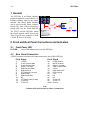
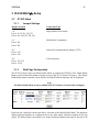
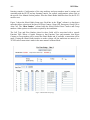
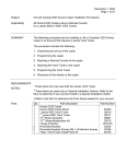
Model NI223plus
IP-223 iDen® Interface
Technical Manual
March 2008
Telex P/N LIT000150000
Revision C
NI223Plus
-3-
Table of Contents
1 General ................................................................................... 4
2 Front and Rear Panel Connections and Indicators ............ 4
2.1
2.2
Front Panel LED ............................................................................................................. 4
Rear Panel Connectors.................................................................................................... 4
3 IP-223/NI223plus Setup............................................................ 5
3.1
IP-223 Setup.................................................................................................................... 5
3.1.1 Jumper Settings........................................................................................................... 5
3.1.2 Web Page Configuration............................................................................................. 5
3.2
Connecting the IP-223 and the NI223plus ....................................................................... 7
3.3
IDen® Radio Setup......................................................................................................... 7
3.4
C-Soft Setup.................................................................................................................... 8
3.4.1 Setup IP Multicast List................................................................................................ 8
3.4.2 Set Global Parameters................................................................................................. 8
3.4.3 C-Soft Phone Control Buttons .................................................................................... 9
3.4.4 C-Soft Radio Line Types: ........................................................................................... 9
4 IDen® Network Calling .......................................................... 9
4.1
Console Selected Calling ................................................................................................ 9
4.2
Manual Connections ....................................................................................................... 9
4.2.1 A-Key, Alert ............................................................................................................. 10
4.2.2 B-Key, Send.............................................................................................................. 10
4.2.3 C-Key, Group Call .................................................................................................... 10
4.2.4 D-Key, Direct Connect Call...................................................................................... 10
5 Audio Alignment Procedure ............................................... 10
5.1.1
5.1.2
Transmit Audio Alignment ....................................................................................... 10
Receive Audio Alignment......................................................................................... 11
6 Cable Assembly ................................................................... 12
7 Warranty, Service, Repair, and Comments ....................... 13
8 NI223Plus Specifications ...................................................... 14
Table of Figures
Figure 1 Multicast Setup Screen IP-223 Showing iDen® Radio Setup ......................................... 5
Figure 2 iDen® Radio Setup Page.................................................................................................. 6
Figure 3 Connections between IP-223 and NI223plus..................................................................... 7
Figure 4 Setup IP Multicast List – iDen® Radio in Phone Mode operation .................................. 8
Figure 5 Setup Global Parameters - Phone Ring Multicast and Port.............................................. 8
Figure 6 C-Soft Phone Control Buttons Setup................................................................................ 9
Figure 8 IP-223 Transmit Audio Gain Setup................................................................................ 10
Figure 9 IP-223 Receive Audio Alignment Example ................................................................... 11
-4-
NI223Plus
1 General
The NI223plus is an iDen® interface
product designed to connect the IP-223
Ethernet Adapter Panel to the iDen®
network. The iDen® Radio Interface
can be used to make Direct Connect,
Group Call, Alert Calls or Emergency
Group calls over the iDen® network.
The IP-223 and the NI223plus makes
the Nextel network an IP asset to any
Telex/Vega IP base consoles (C-Soft,
C-6200, IP-1616 or IP-2002).
NI223
to iDen
LAN/WAN
NI223
To iDen
IP Network
2 Front and Rear Panel Connections and Indicators
2.1
Front Panel LED
POWER:
2.2
Green LED indicates power to the NI223plus.
Rear Panel Connectors
A DB25 connector terminates all connections on the rear of the NI223plus.
Pin # Signal
Pin # Signal
1)
2)
3)
4)
5)
6)
7)
8)
9)
10)
11)
12)
13)
14)
15)
16)
17)
18)
19)
20)
21)
22)
23)
24)
25)
Shield
+12VDC
IP-223 Transmit Data
IP-223 Receive Data
Option 2 (unused)
Radio Receive Data
Radio Audio IN
PTT Relay NO (unused)
Radio DGND
Radio Audio GND
NC
PTT Relay COM (unused)
IP-223 RXIP-223 TX-
IP-223 Ground
MUTE (unused)
Option 1 (unused)
Radio Transmit Data
+5VDC
Radio Audio OUT
RTS (unused)
CTS
NC
NC
IP-223 RX+
IP-223 TX+
Ground
Note
Connect the Earth Ground to reduce system noise.
Analog
NI223Plus
-5-
3 IP-223/NI223plus Setup
3.1
IP-223 Setup
3.1.1
Jumper Settings
Jumper Position
Connection Type
“A”
Line 1: J3, J9, J11, J16, J21
Line 2: J19, J20, J25, J28, J29
Single Ended Tx/Rx Audio
“A”
Line 1: J14
Line 2: J24
600 Ohm Rx Termination
“B”
Line 1: J35
Line 2: J26
Serial Port Communications Jumpers (TTL)
“B”
Line 1: J33, J34
Line 2: J5, J6
4 Wire Interface
3.1.2
Web Page Configuration
The IP-223 must be placed in iDen® Radio Mode to control the NI223plus. The iDen® Radio
Mode is selected from the Multicast Setup Screen of the IP-223 shown in Figure 1. The iDen®
Radio Mode must be initially selected before the iDen® Radio Setup Page may be displayed.
Note
The iDen® Radio Mode is only available in IP-223 Software Versions 1.09 and higher.
Figure 1 Multicast Setup Screen IP-223 Showing iDen® Radio Setup
Each line has a pull down menu that allows selection of the iDen® Radio Mode. The multicast
address and port numbers are configured just as any other mode, with the exception of the ring
signal. The Ring Signal is broadcast on a unique multicast address and must be known to all
-6-
NI223Plus
listening consoles. Configuration of the ring multicast and port numbers must be unique and
consistent with the IP-223 and any listening console. For console configurations, please refer to
the specific User Manual for that product. After the iDen® Radio Mode has been set, the IP-223
must be reset.
Figure 2 shows the iDen® Radio Setup page. Each line in the “Type” column is a drop down
menu that allows selection of the line as a Direct Connect, Group Call, Emergency Group Call or
Alert Call. The “iDen Number” column holds the iDen® Radio Direct Connect and Group
numbers. Other options are selected as required by the installation.
The Call Type and iDen Number placed in these fields will be associated with a console
Function Tone. When a Console changes to that Function Tone and transmits, that Direct
Connect or Group number will be sent to the iDen® Radio and, if available, a connection will be
made. If using the iDen® Radio interface to make a phone call, the multicasts are unused, as a
TCP/IP socket connection is made in the same manner as Phone Mode.
Figure 2 iDen® Radio Setup Page
NI223Plus
3.2
-7-
Connecting the IP-223 and the NI223plus
Figure 3 Connections between IP-223 and NI223plus
Connect the IP-223 and the NI223plus to the iDen® radio as shown in Figure 3. The power for
the NI223plus will be obtained from the same power connector the IP-223 is using. Make sure the
polarities are correct to avoid damaging the units. Figure 3 shows the iDen® Radio configured
for use with IP-223 Radio 1. Radio 1, Radio 2 or both radio ports on the IP-223 may be used. If
both ports are used, a DB9 splitter cable (Telex P/N 301953) is required to route serial channel
one and two to the respective NI223plus devices.
3.3
IDen® Radio Setup
At power up or reset, with the iDen® radio properly connected, the display on the IP-223 should
show “iDen” on the line that was enabled, either the top (line 1) or bottom (line 2) of the display.
If after connecting and configuring the IP-223, “iDen” is not displayed, check the following
items:
• Check all connections as described above.
• From the Multicast Port Setup page, check the iDen® Radio Mode, then reset.
• Check the Jumpers for TTL serial communications.
• Make sure the baud rate of the iDen® radio is set at 19200.
-8-
3.4
NI223Plus
C-Soft Setup
Note
This example shows a basic setup for C-Soft. Please refer to the User manual for other
Vega IP based consoles if necessary.
3.4.1
Setup IP Multicast List
Figure 4 Setup IP Multicast List – iDen® Radio in Phone Mode operation
Figure 4 shows an example of setting two lines in Phone mode. In this example, the Line Type is
selected as Phone mode. The Line Name is arbitrary and called Line 31 and Line 32 in this case.
The Rx port numbers need to be unique; typically they are just the next number in a standard
assignment sequence. The Base Radio IP address will be the IP address of the IP-223 that is
connected to the NI223plus.
3.4.2
Set Global Parameters
Figure 5 Setup Global Parameters - Phone Ring Multicast and Port
Figure 5 shows the Phone Ring Multicast and Port number setting. This value will be the same as
that shown in Figure 1.
NI223Plus
3.4.3
-9-
C-Soft Phone Control Buttons
Figure 6 C-Soft Phone Control Buttons Setup
Figure 6 shows a few of the basic C-Soft Phone Control buttons. Any button can be configured
for a task by Right-Clicking on the button, then using the UI Element Function pull down menu.
In this case, Phone – On/Offhook was selected. The Remote Phone Line Select tab shows that no
specific line was selected as the Phone asset. Instead Pool was selected. In the case of the IP-223,
Pool mode means that if both lines are setup as Phone Mode (PSTN or iDen® System), the open
line will be selected for use when the console tries to connect. This is the same function as the
multi-line telephone. Also shown is an example of a few phone control buttons. Please refer to
the C-Soft manual for further details on the button configuration.
3.4.4
C-Soft Radio Line Types:
To use the IP-223 iDen® Radio interface in Direct Connect Mode, the line type will be the
standard radio type. As shown in Figure 2, each Function tone entry will have a Direct Connect
number association. Simply changing the Function Tone selection will steer the Direct Connect
dial string. The same can be said for Group Call and Call Alert.
4 IDen® Network Calling
4.1
Console Selected Calling
As shown in Figure 2, each Function Tone entry is assigned a Direct Connect, Group,
Emergency, or Alert number. Pressing the Function Tone on the console will route the dial string
to the iDen® phone.
4.2
Manual Connections
The console DTMF keypad may be used to manually initiate Group, Emergency Group, Direct
Connect, Direct Connect, Alert calls or dial a phone number. Using the standard keys, enter the
dial string to be called. The A, B, C, or D keys are used to complete the calling function. C-Soft
allows the user to customize the DTMF button labels. The A, B, C, and D buttons may then be
labeled with the specific iDen® calling function.
- 10 -
4.2.1
NI223Plus
A-Key, Alert
The ‘A’ key is used to send an Alert function over the iDen®
system. Using the standard dialing keys, enter the ID of the
radio. Press the “A” key to send the alert.
4.2.2
B-Key, Send
The “B” key is used as a send button when placing a manually
dialed phone call. Take the phone line offhook, dial the
number, and then press the “B” key to connect the call.
4.2.3
C-Key, Group Call
Enter the group number to be called followed by the “C” key.
When the PTT button is pressed, a group call will be completed.
4.2.4
D-Key, Direct Connect Call
Enter the Direct Connect number then press the “D” key. When
the PTT button is pressed, the Direct Connect call will be
completed.
Figure 7 - Manual DTMF key layout
with iDen® commands
5 Audio Alignment Procedure
5.1.1
Transmit Audio Alignment
The Transmit audio (Audio IN) to the iDen® Radio should not be overdriven. The levels to the
radio should be at or near -5dBm as measured at the IP-223 radio test point on the front of the
unit. The TX Pot on the front panel of the IP-223 will be near 9-12 o’clock depending on the
microphone source. Alternatively, the Software Gains may be adjusted to gain more granularity
in the pot setting to accommodate different microphones. Figure 8 shows an example Transmit
Gain setting. From here a simple talk test will result in good audio levels.
Figure 8 IP-223 Transmit Audio Gain Setup
NI223Plus
5.1.2
- 11 -
Receive Audio Alignment
The standard Receive audio alignment procedures should be followed for the NI223Plus
installation. With AGC turned OFF, inject a 0dBm test tone into the IP-223 front end and
measure the level at the Receive audio test points for line 1 or 2. (TP13 or TP1) The level should
be near, but below 0dBm reference from the test point to ground (TP14, near TP13). This should
result in audio levels from the iDen® Radio at –5dBm to –10dBm as shown in Figure 9. A meter
can be used if the unit is on the bench top, or if installed, the front panel VU meter can be used.
To access the VU meter Press and Hold the line button, then press the IC button three times. A
general talk test is still the best mechanism for ensuring a quality connection. The system can be
tested with a handset from the front panel as well. To purchase the handset, contact the Telex
Vega Sales department.
Figure 9 IP-223 Receive Audio Alignment Example
TO
NC
NC
NC
NC
NC
NC
NC
NC
-
PIN
P1-1
P1-2
P1-3
P1-4
P1-5
P1-6
P1-7
P1-8
P1-9
P1-10
P1-11
P1-12
P1-13
P1-14
P1-15
P1-16
P1-17
P1-18
P1-19
P1-20
P1-21
P1-22
P1-23
P1-24
P1-25
ORANGE
RED
BLK WITH GREEN
BLACK
BLUE
GREEN
BLK WITH WHT
BLK WITH RED
WHITE
BROWN
RED
WHITE
WHITE
RED
P3-J5
P2 RING
P5-14
P3-J10
P3-J9
P5-2
P5-12
P5-13
P4-2
P3-J4
P3-J3
P2 TIP
P5-24
P5-25
16
9
4
4
2
2
1
4
4
4
3
2
1
4
2
2
3
5
5
CABLE No.
WIRING TABLE
UNDERSIDE
COLOR
19
P1
RED
RED
WHITE
22
10
P4-1
P6-9
P6-1
PIN
1
2
21
12
CABLE No. 3
CABLE No. 2
CABLE No. 1
7
6
13
3
15
6
8
11
CABLE No. 5
P4
DETAIL A
SCALE 1 : 1
14
CABLE No. 4
P3
A
17
P2
P5
2
18
4
3
2
1
1
2
2
2
9
1
20
2
-001 ITEM
QTY. No.
6
7
2
5
8
1
1
9
.094
.333
10
11
1
2
12
13
2
1
15
1
14
16
1
17
1
18
1
1
20
19
1
21
1
22
1
P6
1
6
9
66035J
804147
804230-1
803629
804142-6
804142-7
TUBING, SHRINK, 1/2 ID
DESCRIPTION
CONN D 25 PIN MALE SOLDER
8800101954
PART NUMBER
BACKSHELL, 25 PIN D-SUB
CABLE,SHIELDED
HOUSING, D-SUB METALIZE CONNECTOR
CONN, 9 PIN D-SUB MALE SOLDER
SHRINK FIT 221 1/4 BLACK
CABLE, 3 PR 22 GA SHIELDED
BEND RELIEF
TUBING, 3/64 BLACK
CABLE,SHIELDED
TERMINAL STRIP CONNECTOR 3 POLE
CABLE, SHIELDED, 7 CONDUCTOR, GRAY
CLAMP,STRAIN RELIEF,.190,NAT-B
PC BOARD, IDEN INTERFACE CONNNECTOR
CONNECTOR, iDEN 17 PIN DATA PLUG
CABLE, 2.5MM STEREO, 2 FT.
LABEL, TELEX MONOGRAM
LABEL, SMALL, " TO IP223"
LABEL, TELEX KEY
LABEL, LARGE "TO IP-223"
LABEL, LARGE "TO NI223"
ITC000001
58341001
6503681
8800102114
411829
8800227356
63351004
51379001
58341001
21-04-038986
550252
57082000
750735
539237000
EML000050000
4
5
- 12 NI223Plus
6 Cable Assembly
NI223Plus
- 13 -
7 Warranty, Service, Repair, and Comments
Important! Be sure the exact return address and a description of the problem or
work to be done are enclosed with your equipment.
Warranty (Limited)
All Telex Communications, Inc. manufactured Vega Signaling products are guaranteed against
malfunction due to defects in materials and workmanship for three years, beginning at the date of original
purchase. If such a malfunction occurs, the product will be repaired or replaced (at our option) without
charge during the three-year period, if delivered to the Telex factory. Warranty does not extend to
damage due to improper repairs, finish or appearance items, or malfunction due to abuse or operation
under other than the specified conditions, nor does it extend to incidental or consequential damages.
Some states do not allow the exclusion or limitation of incidental or consequential damages, so the above
limitation may not apply to you. This warranty gives the customer specific legal rights, and there may be
other rights which vary from state to state.
Factory Service Center
TELEX Communications, Inc.
Vega Signaling Products
8601 East Cornhusker Highway, Lincoln, Nebraska, 68507
Phone: (402) 465-7026 / (800) 752-7560 Fax: (402) 467-3279
E-mail: [email protected]
Web: www.vega-signaling.com
Claims
No liability will be accepted for damages directly or indirectly arising from the use of our materials or from
any other causes. Our liability shall be expressly limited to replacement or repair of defective materials.
Suggestions or Comments
We’d appreciate your input. Please send us your suggestions or comments concerning this manual, by
fax (402-467-3279) or e-mail them to: [email protected]
Visit our web site at www.vega-signaling.com
Technical Support:
[email protected]
Telephone: 1-800-898-6723
- 14 -
NI223Plus
8 NI223Plus Specifications
Operating Temperature Range:
• 0 to 55°C for full specifications
Front Panel Indicators:
• Green LED Power Indicator
Power Requirements:
• +12 to +16 VDC, semi-regulated, 1A Max.
Rear Panel Connections:
• DB25
• Earth Ground.
Dimensions:
• 2¾”Wx4¾”Dx1¾”H
Specifications are subject to change without notice
Accessories:
•
•
DB9 Splitter Cable Assembly, Telex PN 301953
19” Rack Mount Kit Telex P/N DSP223RACK (holds up to 4 NI223Plus boxes)
TELEX Communications, Inc.
Vega Signaling Products
8601 East Cornhusker Highway, Lincoln, Nebraska, 68507
Phone: (402) 465-7026 / (800) 752-7560 Fax: (402) 467-3279
E-mail: [email protected], Web: www.vega-signaling.com