1
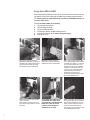
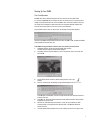
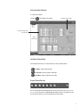
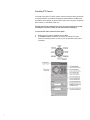
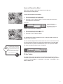
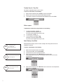
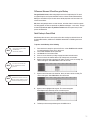
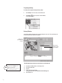
Set-up and Instruction Manual
©2009 i³DVR International Inc.
The contents of this user manual are protected under copyright
and computer program laws.
INNOVATIONS AT THE SPEED OF THOUGHT
™
SRX-Pro DVMS
Thank you for purchasing the i³DVR Digital Video Management System (DVMS). The following items
should be included in the i³DVR DVMS box. If any of these items are missing, please contact your
dealer or call our Customer Care Department toll free at 1.866.840.0004.
Typical Rackmount DVMS (RM)
Video pigtail cable - 10 or 16 BNC
inputs depending on the model
(not included with all DVMS models)
Keyboard
Typical Compact Wallmount DVMS (CW)
Audio pigtail cable - 4 or 8 RCA
inputs depending on the model
(not included with all DVMS models)
USB Mouse
Power cord
Additional accessories:
•
•
•
•
•
•
•
•
•
Rack Ears and Handles
(RM models only)
Wallmount Bracket
(For CW units.
Only if purchased)
18 small black bracket screws (only with purchased Wallmount Bracket)
8 small silver hard drive screws (with CW units only)
4 black bracket screws, 16 small silver hard drive screws, 2 SATA keys (with RM units only)
System recovery DVD (also taped to the inside of the DVMS top cover)
SRX-Pro Server and Remote software CD
SRX-Pro video tutorial CD
Motherboard manual and/or CD(s)
Video card driver CD (not included with all DVMS models)
Additional accessories may include USB SIIG card, USB Network card, and/or POS cables as per customer
order
Precautions:
When selecting a storage location for your system, be sure to avoid:
•
excessive heat, such as direct sunlight or heating appliances
moisture, dust, and smoke
• magnetic fields or electrical waves
• temperatures below 5º Celsius or 41º Fahrenheit
• any obstructions to the system’s ventilation holes
•
Before installing this system, always ensure the:
•
•
•
•
•
•
power source is located within 3 feet or 1 meter of the UPS
power is switched off (**Do not plug in the DVMS unit)
system and its connecting cables have sufficient space
system is placed on an even surface
system is situated far from electronic equipment such as microwaves, radios, fridge compressors, or any
type of wireless equipment such as telephones or cell phones)
system is at room temperature (18º – 25º Celsius or 64º – 77º Fahrenheit)
2
Setting Up the SRX-Pro DVMS:
Before installing SRX-Pro DVMS, ground yourself. This will remove any static electrical charge your
body might be carrying. Before powering up the DVMS, connect all cables and peripheral devices
first. Uninterrupted power supply (UPS) must be used with the i³DVR DVMS; otherwise, all
warranties will be voided.
To set up the SRX-Pro DVMS, do the following:
1. Plug in the mouse and keyboard.
2. Plug in the monitor VGA cable.
3. Plug in all the BNC video cables.
4. Plug the power cable into the DVMS. (Do NOT power up)
5. Plug the power cable into the UPS (uninterrupted power supply).
6. Power up the system.
3
Step 1: Plug the mouse into the USB port.
Depending on the DVMS model, you will receive
either USB or PS2 keyboard. Plug the keyboard
into either a purple-colored PS2 port or USB
port depending on keyboard connection type.
Step 2: Plug the monitor cable into the
VGA connector on the video card (or on the
motherboard for Ultra Lite and Lite models)
Step 3: Connect the BNC Cables to the BNC
Ports. 1. Begin connecting the BNC video cables
to the i³DVR server’s BNC ports. 2. Ensure they
are secure and locked into position. 3. Once
completed, ensure that the 75Ω impendance
dip switches are in the upward position. This
is necessary in order to terminate the video
signals. NOTE: The dip switch terminal is
located below the Loop Out ports for
the Rackmount, and below the video in/output
for the Compact Wallmount chassis.
Step 4: Connect the power cable to the power
supply on your DVMS.
NOTE: At this point, locate the power switch
next to the power plug and make sure it is in the
OFF position.
Step 5: CONNECT THE POWER CABLE TO
AN UNINTERRUPTIBLE POWER SUPPLY
(UPS). IMPORTANT: AN UNINTERRUPTIBLE
POWER SUPPLY (MIN. 500 VA) MUST
ALWAYS BE USED; OTHERWISE ALL
WARRANTIES WILL BE VOIDED.
Step 6: Turn the power switch in the back of
the system to the ON position. The system will
then power on automatically. If this does not
happen, press and hold the power switch for 2
seconds. The system will then power up.
NOTE: The power switch is located at the front
of your DVMS (toggle button switch)
Starting Up Your DVMS
Time Zone Adjustment
All DVMS units sold by i³DVR International are pre-set to Eastern Time zone (GMT -5:00).
It is, therefore, imperative that you configure the time zone setting on the first system startup according to the physical location of the unit. If the DVMS is later re-located to a different time zone,
this setting must be changed once again. All previously-recorded data should be formatted after
each time zone change. Failure to do so may result in system malfunction.
Once the SRX-Pro Server starts for the first time, the following message will be displayed:
Click Yes if the DVMS is being installed in the Eastern time zone (GMT -5:00). Click No if the DVMS
is being installed in a different time zone.
If the DVMS is being installed in a different time zone, follow instructions below:
1. On Windows Desktop, go Start ► Control Panel ► Date and Time
The Date and Time Properties window will be displayed.
2. In the Date and Time Properties window, go to the Time Zone tab, select correct time zone
and click OK.
3.
4.
Launch SRX-Pro Server software by double-clicking the Server icon on the
Desktop.
Once the software loads, the following message will be displayed on the screen.
5. 6.
7.
Click OK (highly recommended) to format all storage drives and erase video data recorded in
a different time zone.
Click OK in the “All old data will be formatted” warning window, Allocation window will be
displayed in the top left corner.
Wait until the “Start allocating selected drive(s). It may take several minutes to finish.”
message changes to “Storage Drives have been allocated”. Click OK in the Allocation
window to close it.
The login window will be displayed on the screen. Follow instructions in First Login section.
4
First Login
Once the SRX-Pro Server software starts, a login window appears:
FOR DETAILED INSTRUCTIONS
Please refer to the complete
SRX-Pro manual. To access,
login first, then click Help menu
and select Help Index.
NOTE
1.
To log into the system, type your user name and password.
2.
If logging in for the first time, enter user for User Name and user for Password.
For administrative account, enter
i3dvr for User Name and i3dvr for
Password.
Virtual keyboard
Use the virtual keyboard
if keyboard is not available
5
Activating Video Channels
To activate video channels:
Click Setup.
The following screen appears:
Scroll down for more channels
Activate channels by clicking
on the checkboxes
SRX-Pro
Control Centre
Live/Search/Setup Mode
The following buttons allow you to switch between Live, Search and Setup modes:
Live Mode - Allows viewing live video.
Search Mode - Allows searching recorded video.
Setup Mode - Allows configuring server settings.
Screen Division Buttons
The screen division buttons allow displaying video channels on the main screen in a 4-, 6-, 9-,10-,
13-, 16-, or 25-screen division. The Full Screen button displays the live screen without user interface (no menu bars shown). To exit, press the Esc button on the keyboard.
6
Controlling PTZ Cameras
It is possible to control the PTZ cameras remotely. Please ensure that the camera you would like
to control has PAN/TILT text displayed in the appropriate channel window on the Main Screen.
If no PAN/TILT text is displayed, the selected camera is either fixed, is not properly configured in
SRX-Pro Server, or is controlled by another user.
Each PTZ camera can be controlled by one (1) user at a time. If another user is already
controlling the PTZ camera remotely, the PTZ controls will not be displayed.
To control the PTZ camera, follow instructions below:
1. 2. 7
Double-click the PTZ camera in the Main Screen (Live Mode).
Click Advanced Control in the SRX-Pro Control Centre to show the PTZ controls.
Use the PTZ control panel to Pan, Tilt, Zoom, or Focus the camera and to adjust speed
or brightness.
Search and Playback (Live Mode)
SRX-Pro allows searching the specific video channels in the Live Mode view,
while monitoring the remaining channels.
To access the search mode, do the following:
1.
2.
3.
Right-click on the desired channel in the Live Mode.
From the Context Menu, select Search Mode.
Repeat steps 1 and 2 for all desired channels. The 24-hour timeline with control buttons will be displayed for selected channels.
Channel number
To return to the live mode, do the following:
1.
2.
3.
You can move the timeline
anywhere in the channel view box
by left clicking on the time line and
moving in to desired position
Right-click on the desired channel in the Live Mode.
From the Context menu, select Live Mode.
Repeat steps 1 and 2 for all desired channels.
The red timeline marker indicates the playback start time. To change the playback start time, use
the mouse to move the red marker.
The exact time will be displayed inside the timeline on the mouse cursor roll-over. Note that the rollover time is displayed for the mouse cursor and not the red timeline marker. In the example below,
the red timeline marker is positioned at 5:20AM, while the mouse cursor is pointed at 12:00PM.
The roll-over time displayed inside the timeline is 12:00:00 PM.
NOTE
To search the video data recorded
outside of the current 24-hour time
line, please click the Search icon on
the main screen to go to the Search
Mode, where the video recording
may be searched by date & time.
24-Hour Timeline
The timeline provides a visual representation of the recorded data for the 24-hour period. The recorded data is represented by multi-colored bars. The color of the bar indicates the type of the video
recording: For example, emergency = red, continuous = pink, sensor = orange, motion = blue or
sensor + motion= green
8
Timeline Zoom In / Zoom Out
The timeline is expanded by default for ease of search.
To zoom out of the timeline, do the following:
1.
2.
3.
Right-click on the timeline and select Zoom Out, from the Context Menu.
Repeat to zoom out twice. Entire 24-hour timeline will become visible.
To zoom back in, right-click on the timeline and select Zoom In from the Context Menu.
Video Playback
To playback the recorded video using the timeline, do the following:
1.
2.
3.
To start/resume playback, click Play.
Click again to increase the playback speed.
The current speed is displayed in the top left corner.
To stop playback, click Stop.
To reverse playback, click Reverse.
Click again to increase the playback speed.
The current speed is displayed in the top left corner.
Quick Backup in Live Mode
NOTE
9
Please avoid using the
CD-RW/DVD-RW.
DVD-R media preferred
NOTE
The start time will be marked with
the broken green line.
NOTE
The end time will be marked with
the broken red line.
Quick Backup allows saving a portion of the video recording in AVI or Encrypted format onto the
CD-R/DVD-R or hard drive.
To perform a Quick Backup, do the following:
1.
2.
3.
4.
Right-click on the desired channel in the Live Mode.
From the Context Menu, select the Search Mode.
Position the mouse cursor over the desired start time.
Right-click on the timeline and select Mark Start from the context menu.
In the example below, the start time is 11:42:00 AM. Position the mouse cursor over the
desired end time.
5.
Right-click on the timeline and select Mark End from the context menu. In the example below,
the end time is 11:46:00AM.
6.
Right-click on the timeline and select Export from the context menu to proceed with the
backup.
7.
The following message window will appear. Click OK to close it.
Search and Playback (Search Mode)
SRX-Pro allows the user to search specific video channels in the Search Mode view. Several
channels can be searched simultaneously. The Search Mode features a larger timeline, which
simplifies the backup process.
Click Search to access the Search mode
. The Search window will appear.
2
1
3
4
5
6
7
8
10
1. 2. 3. 4. 5. Search view window
Calendar. In the calendar window, select the Date and Start Time for the search.
Tools panel. For backup options, click Backup in the Tools panel.
Advance/Image panels. Index/Object search is available from the Advance panel. A still image can be edited with the buttons from the Image panel.
Playback control panel
Skip to the beginning of the recorded data
View previous frame
Reverse playback
Stop
Play
View next frame
Skip to the end of the recorded data
Individual Search – check off to select a different start playback time for different channels
Speed – By adjusting the Speed scrollbar, configure the speed of playback. By default, the
video is played back at a regular (1X) speed. To increase the playback speed, drag the scroll
bar to the right, to reduce the playback speed, drag the scrollbar to the left.
6. Channel selection buttons. Click the buttons to select specific channels for search.
7. 24-hour Timeline
8. Current date and time
To search specific video channels, do the following:
1. Click the channel selection buttons in the timeline to select the desired video channels.
2. Use the playback control panel to control the playback for selected channels.
Tools Panel
11
Print. To activate the Print function, double-click the desired video channel. Click Print to print the still image on the connected printer.
Zoom In / Zoom Out / Drag. Click Zoom button to switch between the Zoom In, Zoom Out and Drag functions. The user can zoom in or out of a still image and drag the enlarged image on the display screen.
Bookmark. Click Bookmark button to save the exact time of the video recording, so that it can be quickly located on the timeline later.
Backup. Click Backup button to save the still image on the local or remote media or to access the video Backup Sessions list.
Differences Between AVI and Encrypted Backup
Encrypted (default format): allows saving multiple cameras in a single backup file. The saved
encrypted backup file can be opened with SRX-Pro Server or Remote software (Advanced Data
Manager) or with SRX-Pro Player. All saved cameras will be played back at the same time in the
selected screen division.
AVI: allows saving multiple cameras at a time. However, each video channel is saved in a separate
file. During playback, the files are opened with any Windows media player – one-at-a-time. This type
of video backup does not require any additional software and can be opened on any PC that
operates on Windows OS.
Quick Backup in Search Mode
Quick Backup allows the user to save a portion of the video recording from the hard drive to the
local/removable hard drive, a USB drive or CD-R/DVD-R media in AVI or i³DVR Encrypted format
(default).
To perform a Quick Backup, do the following:
NOTE
Please avoid using the CD-RW/
DVD-RW media.
DVR-R media preferred.
NOTE
Start time on the Timeline has
been marked with the broken
green line
NOTE
End time on the Timeline has been
marked with the broken red line and
the video segment between start and
end time lines have been grayed out.
1. 2. 3. 4. 5. 6. Ensure that there is enough free space on the D drive - at least 650MB should be available.
If no drive/partition D is present, drive C will be used.
Insert a blank CD-R/DVD-R into the optical drive.
Click Search to access the Search mode.
Select one or more channels by clicking on appropriate channel selection buttons.
Set the start time in the Calendar window or by clicking directly on the timeline.
Right-click on the data area on the Search Bar, where you want to start the recording. The
context menu appears. Select Mark Start to select the start time.
7. Right-click on the data area of the Search Bar, where you want to end the recording. The context menu appears. Select Mark End to select the end time.
8. Right-click on the highlighted video segment. The context menu appears. Select Export to save the backup session to the Backup menu.
9. The Backup session message window appears. Click OK to close it.
12
Completing Backup
To view, edit or complete backup session(s), either:
1. Select Backup in the Tools menu (if in Live Mode), OR
2. Click Backup,
in the Tools panel (if in Search Mode).
A new window appears.
Backup Window
In the Backup window, all backup clips are saved awaiting the user action. The saved backup clips
may be previewed, edited, deleted or completed.
Make sure the
“Video” backup type
is selected
Select all desired
channels by clicking
on the checkboxes
The following backup parameters may be edited for each backup clip:
NOTE
13
To save any changes to the selected
backup clip, click Update in the
bottom of the window.
To perform any action, the clip has
to be check marked in the list.
1. 2. 3. 4. 5. Destination: CD/DVD (default); Local Storage; Email
Start and End Date/Time
Channels
Format: AVI; Encrypted (default)
To change format to AVI, open Channels ► Video Settings tab
AVI Embedded Text
Add a new backup session. Adds a new backup clip based on the configured
Start and End Date/Time.
Delete selected backup session(s).
Start creating a new backup file. Starts the backup for the selected backup
clips.
Stop creating a complete backup file. Interrupts the backup session already
in progress.
In the example below, Clip 1 backup session has already been finished. Clip 2 backup session is
ready for backup, and Clips 3 and 4 backup sessions are in progress. Three out of four backup clips
are in I3DVR Encrypted format, one clip is in AVI format. All clips are being saved onto CD/DVD
media.
Snapshot Backup
To perform a snapshot backup, do the following:
1. 2. 3. 4. 5. In the Search mode, select the channel for playback.
Double-click, the selected channel to display it separately in the view screen.
On the Playback Control panel, click Play.
Stop the playback at the desired frame.
In the Tools panel, click Backup button
.
The following screen will be displayed:
Make sure the “Snapshot”
backup type is selected
14
In the Snapshot Backup window, you can:
1. 2. 3. 4. 5. Change the file name and backup destination folder.
To change the file name, click Browse ... in the File Name field. Select the destination folder and enter the desired file name. When finished, click Save
to return to the Backup window. Click Save again in the bottom of the screen to save the
snapshot onto the chosen drive/media.
Change the snapshot format.
To change the snapshot format, click Browse ... in the Image Format field.
Choose BMP or JPEG format in the drop-down menu.
Change image quality.
To change the image quality, adjust the Image Quality slider.
Print the selected image.
To print the snapshot, click Print in the bottom of the window.
Save the snapshot to the chosen destination.
To proceed with the snapshot backup, click Save in the bottom of the window.
Remote viewing minimum requirements:
•
•
•
•
•
•
•
•
•
•
15
CPU: Celeron 1.7 GHz
RAM: 256 MB Memory
Graphics: Radeon 64 MB AGP video card
OS: Windows XP
Monitor: 1024 x 768 screen resolution, 32 bits colour minimum
Hard drive: Minimum 1.5 GB free hard drive space
High speed internet
.NET 3.0 framework must be installed onto the system
Microsoft Visual C++ 2005 SP1 Redistributable Package (x86) must be installed onto the
system
Nero 6.6.1.15 must be installed on the system to support all backup features
NOTE: SRX-Pro Remote software relies on Nero 6.6.1.15 software to perform all backup
functions, therefore the supported Nero version must be installed onto your computer.
Nero 7 and Nero 8 are not supported by SRX-Pro software at this time.
Provided the required Nero software version has not been previously installed on your
computer, you must install Nero 6.6.1.15 software before using SRX-Pro Remote.
Creating a New Remote Site Connection in SRX-Pro Remote
To create a new Server connection, do the following:
1.
2.
NOTE
When the Dynamic IP domain service
is used, the network administrator
must open all required ports.
3.
In the left-hand panel click the Add/Edit Server icon:
Complete the Add a new site window
a. Enter the Server ID – (a maximum of 31 alphanumeric characters). This must match the remote Server ID as entered in the Server Information Setup. (Case sensitive)
b. Enter a Server Name – (a descriptive name for the server). For example
“Toronto office”
c. Enter the Server IP address. This must match the remote Server IP address. Unless SRX-Pro Server has a static IP address or a Dynamic IP domain service, the
remote connection will not be established.
d. Edit the Main Control Port if necessary (must match Server setting)
e. Enter the user name and password. (Case sensitive)
When trying to connect to the remote server, the system will check the Server ID,
user name and password together. If either of the variables is incorrect, the Remote
software will not be able to connect to the site.
f. Click Add to save the new connection.
When information for the new site is completed, it will appear on the left-hand side panel.
a. Double-click on the server name to connect.
b. Click on the Disconnect Server icon to disconnect from server.
c. Click on Delete Server icon to remove the server from the remote connections list.
d. Click on the Add/Edit Server icon to edit the connection information.
Connection status/disconnect
Connect to site
Site editor
Delete Selected site
16
Switching Between Connected Servers
Only one connected remote server is active at each given time.
To search or configure setup for the specific server it MUST be active.
To switch between connected remote servers, do the following:
1. 2. 3. 4. Select the desired inactive remote site in the Servers list.
Right-click and select Active from the context menu.
The server icon will change from to
.
To deactivate server, select the desired active remote site in the Servers list.
Right-click and select Inactive from the context menu. The next connection on the list will
become active.
Environmental Requirements for Installation of the DVMS
•
•
•
•
•
Elevated Operating Ambient - If installed in a closed or multi-unit rack assembly, the
operating ambient temperature of the rack environment may be greater than room ambient.
Therefore, consideration should be given to installing the equipment in an environment
compatible with the maximum ambient temperature (Tma) specified by the manufacturer.
Reduced Air Flow - Installation of the equipment in a rack should be such that the amount
of air flow required for safe operation of the equipment is not compromised.
Mechanical Loading - Mounting of the equipment in the rack should be such that a hazardous condition is not achieved due to uneven mechanical loading.
Circuit Overloading - Consideration should be given to the connection of the equipment to
the supply circuit and the effect that overloading of the circuits might have on current
protection and supply wiring. Appropriate consideration of equipment nameplate ratings
should be used when addressing this concern.
Reliable Earthling - Reliable earthling of rack-mounted equipment should be maintained. Particular attention should be given to supply connections other than direct connections to the branch circuit. For example, use of power strips.
WARNING: Risk of Explosion
There is a risk of explosion if the system battery is replaced with the incorrect type of battery.
Dispose of used batteries according to the instructions.
If you have any further technical questions, please contact our technical support
at 1-877-877-7241.
17
i³DVR INTERNATIONAL INC.
1.866.840.0004
www.i3dvr.com
U.S.A. 440 Lawrence Bell Drive,
Suite 16, Williamsville.
NY, 14221
Canada 780 Birchmount Road,
Unit 16, Scarborough.
ON, M1K 5H4