1
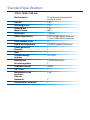
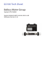
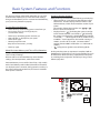
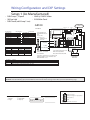
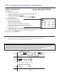
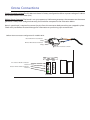
MARS
USER’S GUIDE
WM00175
MARS SPA
User’s manual
_____________________
Version: 01.2014
Standard Specification:
2130×1600×780 mm
Shell material
Persons
Reclining places
Sitting place
Water volume
Net weight
Power requirement
Total number of jets
Hydro massage pump
Ozone generator
Diverter
Filter
Chromotherapy
lighting
Heating unit
Air inlet regulator
Computer control
3/4” Drain
Maintenance-free
Synthetic
Cabinet
Headrests
Thermo cover with lock
PU reinforced antimicrobial
acrylic (6,3 mm)
3 Prs
2 Prs
1 Prs
660 l
~250 kg
1×25 A (230V/50Hz) optimum
1×16 A (230V/50Hz) minimum
37
1×2 HP 2 speed (230V/50Hz)
1
1
1
12×1 LED
1 (3kW/230V/50Hz)
3
VL260
1
1 set
2
1
Warranty letter
Serial number:...............................................
Model: .............................................................
Distributor
Retailer
Date of buying:
Date of buying:
Signature:
Signature:
(stamp)
(stamp)
2013 MyLine Spa Limited Warranty
WARRANTY FOR EXPORT
Warranty; Limitations of Liability and Damages.
Company offers a limited warranty comprised of replacement of faulty parts and offers no
reimbursement for labour of repairs outside any abnormal failure rates to be determined by
both parties.
5 years on spa shell: WELLIS warrants the structure of the spa shell against defects in workmanship and material for a period of 5 years, subject to the limitations and conditions listed
in this Warranty.
3 years on spa shell surface: The acrylic spa shell is warranted against cracking, blistering or
delaminating due to defects in materials or workmanship for three years from the original
date of delivery.
2 years on spa plumbing: Spa fittings and plumbing are warranted against leaks due to defects in materials or workmanship for two years from the original date of delivery. There is no
labour coverage on internal jet parts replacement, cleaning or adjusting.
2 years on standard and optional spa equipment – Balboa Control Systems, Jet Pump(s),
Laing Circulation Pump, Heater, Wi-Fi module, IR receiver: The spa equipment systems are
warranted against failure due to defects in materials or workmanship for two years from the
date of delivery. Fuses, bulbs, and seals are not covered.
2 years on Pulsar hydrotherapy system: The factory installed Pulsar hydrotherapy systems are
warranted against failure due to defects in materials or workmanship for one year from the
original date of delivery.
2 years on spa cabinets/skirts: The factory installed spa cabinets/skirts are warranted against
failure due to defects in materials or workmanship for one year from the original date of
delivery.
2 years on ozone generator: The ozone generator is warranted against failure due to defects
in materials or workmanship for one year from the original date of delivery.
2 years on audio system components: The factory installed audio components (i.e. power
supply, speakers, wires, etc.) are warranted against failure due to defects in materials or workmanship for one year from the original date of delivery. There is no in-field labour service on
these items.
2 years on LED lights: The factory installed LED lights are warranted against failure due to
defects in materials or workmanship for one year from the original date of delivery.
2 years on UV-C sanitizer lamp: The factory installed UV-C sanitizer lamps are warranted
against failure due to defects in materials or workmanship for one year from the original date
of delivery.
2 years on I.S.I.S. water disinfection system: The factory installed I.S.I.S. water disinfection systems are warranted against failure due to defects in materials or workmanship for one year
from the original date of delivery.
1 year on blower: The blower is warranted against failure due to defects in materials or workmanship for one year from the original date of delivery.
1 year on thermo cover: The thermo cover is warranted against failure due to defects in materials or workmanship for one year from the original date of delivery.
1 year on WELLIS Spa Umbrella: The factory installed WELLIS Spa Umbrellas are warranted
against failure due to defects in materials or workmanship for one year from the original date
of delivery.
1 year on LCD TV system: The factory installed LCD TV systems are warranted against failure
due to defects in materials or workmanship for one year from the original date of delivery.
90 days on skimmer house: Skimmer houses are subject to water chemistry variation and
are warranted for ninety days from the original date of delivery. NO warranty on filters, spa
pillows and skimmer house tops.
WARRANTY PERFORMANCE
1.
This warranty does not cover cleaning or adjusting spa or for customer error in following
correct procedures.
2.
WELLIS Magyarország Kft. reserves the right to substitute a spa or component of equivalent value, either new or factory reconditioned and any such repair or replacement
shall assume as its warranty only the remaining portion of the warranty on the original
product.
3.
WELLIS Magyarország Kft. is not liable for any costs associated with in-ground, in-deck,
or in-home installations or removal. Costs associated with installations other than
standard residential portable spa use will be the sole responsibility of the spa owner.
The spa owner is responsible for any freight and/or delivery and set up charges for a
replacement spa.
4.
The radio reception is not covered under warranty due to the following: The radio signal
reception may be impaired by the positioning of the spa next to or near structures, high
power lines, main power lines or metallic towers. The signal reception may be impaired
if the spa is located near hills or it is in a valley or simply outside the broadcasting range
of the radio stations. The position of the spa and radio may be “out of phase with the
bandwidth” or the radio frequency. External signal reception assistance may be required
and is not part of this warranty.
5.
WELLIS Magyarország Kft. shall not be liable for any incidental or consequential damages for breach of any expressed or implied warranty, breach of contract, negligence, strict
liability, or any other legal theory related to this product. All consequential expenses
including loss of use, damages, or contingent liabilities arising out of any alleged deficiencies of the spa are specifically excluded from this warranty.
6.
Warranty coverage is only extended to the original buyer. Spas purchased from anyone
other than a current WELLIS Spas Authorized Dealer are specifically excluded from any
warranty coverage. To obtain warranty service, please notify your WELLIS Spas Authorized Dealer in writing within 14 days of the problem (with problem details, original
proof of purchase).
7.
The Authorized Dealer will repair or replace any component found defective under the
terms of this warranty – and permitted by WELLIS Magyarország Kft. Travelling expenses
may apply outside of every European cities.
8.
If the Authorized Dealer doesn`t supply the customer with proper service, please notify
WELLIS Magyarország Kft. by mail within 10 days of the problem.
9.
Electrical connection: All electrical connections are required to be done by a qualified
electrician solely. The spa has to be connected to separate current circuit equipped with
suitable power switch and life safety relay. Omission of these electrical conditions/requirements entails immediate loss of the warranty.
10. Water connection: All water connections are required to be done by a qualified plumber
solely. If the spa is placed indoor make allowances for the following special requirements: The water accumulates around the spa so the socket cover has to be in possession of a suitable drainage. This arrangement hinders the water in collecting.
11. WELLIS Magyarország Kft. offers a limited warranty as described in the Warranty Letter.
12. Warranty claim is enforceable with this warrant letter. Irregular establishing of this
warrant letter doesn`t affect to the validity of warranty obligation. If customer doesn`t
get this warrant letter from the Authorized Dealer, it doesn`t affect to the validity of
warranty obligation.
SPA WARRANTY COVERAGE WILL BE VOID
UNDER THE FOLLOWING CONDITIONS
1.
If damages caused by inefficient maintenance of water and/or chemical dosage.
Terms of water hardness (limits): between 6-10 German degrees.
2.
If the spa surface or equipment has been damaged or discoloured as a result of improper water chemistry maintenance, including sanitizers such as trichlor type chlorine,
calcium hypochlorite, sodium hypochlorite, and any other chemicals or a chemical
dispenser that may rest on the spa surface. Some household cleaners can damage the
spa shell or equipment and will void this warranty completely. Use only products that
are recommended for spas.
3.
If damage to the spa has resulted from an Act of God, force majeure, moving of the
spa, improper installation, unstable power conditions, customer negligence, customer
abuse, weather and sunlight damage or damage caused in shipment.
4.
If damage to the spa has resulted from operation outside – temperature exceed 45°C.
5.
If the spa has been subjected to any alterations, after-market product installations, misuses, abuses, or if any repairs are attempted by anyone other than its authorised dealers.
6.
If damage to the spa has resulted from improper use of thermo cover.
7.
If damage to the spa has resulted from clogged, dirty and/or clogged filter. The spa warranty will be void if the owner does not follow all the instructions in the owner’s manual
regarding the proper use and care of the spa. Warranty doesn`t apply to filters!
8.
If damage to the spa has resulted from improper electrical installation, voltage drop,
peak voltage and/or operation is outside the pale of + / - 10% voltage range.
Electrical conditions:
For electrical installation it is required to build a 30mA circuit breaker (life safety relay),
which is just connected to the spa (not allowed to connect any other devices). This 30
mA circuit breaker is not permitted to be installed in the same place as the spa.
Required to install IEC, RCCB system in spa`s common surroundings.
Length of cable is 3 meters at the place of spa installed.
It is obligatory to observe all information, details and requirements which are in the
product`s installation diagram regarding electricity demand and drain installation.
These information can be found in the user manual, or able to download from www.
wellis.eu. If you didn`t get the document from your dealer, please contact support@
wellis.eu.
If damage to the spa has resulted from debris in jets (i.e. sand, dirty calcium, leaves etc.).
9.
Warranty doesn`t extend to the waste water manifold (drain hose), pillows, filters, bulbs
and/or pump sealing.
LIMITATIONS
The Warranty expressions specified excludes any other implied or oral undertakings. Purchasers also have current rights under statute which will be respected by WELLIS Magyarország
Kft. After a period of 12 months, for the purpose of assessing WELLIS Magyarország Kft.
liability, all aspects covered by this Warranty will be treated on a pro-rata basis. WELLIS
Magyarország Kft. or its agents will not be liable for any incidental or consequential loss or
injury. Nor will WELLIS Magyarország Kft. be liable for costs associated with but not limited to
building alterations or finishes and under no circumstances will be liable for greater expense
than the amount paid for the product.
THE SPA OWNER MUST DO EVERYTHING STATED IN THE SPA OWNERS MANUAL
AND WARRANTY LETTER TO SAFEGUARD AND MAINTAIN THE SPA!
MANUFACTURER OF YOUR SPA:
WELLIS Magyarország Kft.
Registered:....................................31/C, Budaörsi út, H-1118 Budapest, Hungary
Central premise:..........................hrsz: 0417, Mánteleki út, H-2371 Dabas, Hungary
AUTHORIZED DEALER OF YOUR SPA
Company in charge of your spa
Company name:.........................................................................................................................................................
Registered: ...................................................................................................................................................................
Central premise: .......................................................................................................................................................
Place of complaint: ................................................................................................................................................
E-mail address: ..........................................................................................................................................................
Website:......................................................................................................................................................................
Phone number: .........................................................................................................................................................
Fax: ..................................................................................................................................................................................
Person in charge of installation: ..........................................................................................................................
Date of installation: .................................................................................................................................................
Service-work
The announcement date of damage:
_____________________________
Date of received goods/parts for repair:
_____________________________
Date of the return of repaired goods/parts: _____________________________
Date of site service:
_____________________________
Improved error:
_____________________________
Mode of repair:
_____________________________
Failed component:
_____________________________
New deadline for the warranty:
_____________________________
A
stamp
B
stamp
C
stamp
D
stamp
SAFETY INSTRUCTIONS
ATTENTION: PLEASE READCAREFULLY AND FOLLOW THE INSTRUCTIONS
AVOIDING THE RISK of injury of CHILDREN
1. In order to reduce the risk of injury to children, do not allow children to use this spaalone
unless they are carefully supervised at all the times.
2. Lower water temperatures arerecommended for young children. Please test the water
temperature with yourhands before allowing children to get into the spa, and make sure
it iscomfortable for children’s usage.
3. Remember that wet surfaces can be slippery, please remind children to be careful when
entering or exiting the spa.
4. Don’t permit children to climb onto the spa cover.
AVOIDING THE RISK of injury of bathers
1. In order to reducing the risk of injury to bathers, do not remove or lose anysuction fittings. Never operate spa if the suction fitting are broken or missing.
2. Remember that wet surfaces can be very slippery. Take care of a danger ofslipping and
falling when entering or exiting the spa.
3. For the sake of health, people with infectious diseases should not be allowed touse the
spa.
4. Keep any loose articles of clothing or hanging jewelry away from rotating jets orother
moving components.
5. The use of drugs, alcohol or medicine before or during spa use may lead to unconsciousness with the possibility of drowning. Persons using medicines shouldconsult a physician
before using spa; some medicine may cause a user to becomedrowsy. While other medicine may affect heart beating, blood pressure changing and circulation problem.
6. Pregnant women should consult a doctor before using the spa.
AVOIDING TNE RISK OF ELECTROCUTION
1. Test the ground fault circuit interrupters before use. Must always to be connectedto a
circuit protected by a ground fault interrupt.
2. Check the power cables cord, a damaged power cord may result in death, or seriouspersonal injury due to electrocution. Do not use the spa with damaged power cable, change
that immediately before using and need to disconnect the spa from power supply.
3. Do not permit any electrical appliances, such as a light, telephone, radio, or television
within 1,5m of a spa. Keep a safe distance from spa, because this failure may result indeath, or serious injury due to electrocuting if the appliance should fallinto the spa.
4. Install your spa in such a way that drainage is away from the electricalcompartment and
from all electrical components.
5. Disconnect the spa from the power supply before servicing the electricalcomponents.
NOTICE:
Your spa is anequippedwith two/three massage pumps that allow you tooperate eachpart of
the jet system separately or all valves simultaneously.
Do not connect power to an empty spa. Otherwise the components such ascontroller, heater,
circulation pump, and other systems could be damaged.
INSTALLATION INSTRUCTIONS
SITE PREPARATION
1.
INDOOR/BASEMENT INSTALLATION
If you take it place your spa indoors, be aware of some special requirements. Water
willaccumulate around the spa, so the flooring materials must provide a good grip
whenwet proper drainage is essential to prevent a build-up of water around the spa.
When building a new room for the spa it is recommended that a floor drain isinstalled.
The humidity will naturally increase with the spa installed water may getinto woodwork
and produce rot, mildew or otherproblems. Check for airborne moisture’s effects on
exposed wood, paper, etc in theroom .To minimize these effects, it is best to provide
plenty of ventilation to the spa area.
2.
OUTROOR AND PATIO INSTALLATION
It is important that you have solid foundation to support the new spa when youinstall
it .Tobe certain your deck or foundation can support your spa. You mustknow the deck
maximum load capacity. Consult a qualified building contractor orstructural engineer.
To find the weight of your spa, its contents and occupants, please refer to the spa specification chart. This weight per square foot must notexceed the structure’s rated capacity:
otherwise serious structural damages couldresult,if you install the spa outdoors we
recommend a reinforced concrete pad a tleast four inches thick. Don’t forget to install
some floor drains around your spa sothat it can take the water away during and after the
heavy rain.
INSTALLATION
1.
2.
3.
4.
Please read and study the OWNER’S MANUAL carefully. Please finda professional people
to install and setup for first time.
Remove the package, and take down the new spa on the prepared foundation.
Open the control box compartment under the display by loosenthe screw and then
open the control box. Prepare the accordingly cooper cable(the length will be enough
to connect to the power supply), with electricalplug one side and another side without
plug and then take the empty side of cablefrom electrical cable. Lead the cable through
the pump compartment to the channelof control box compartment.Connect the electrical cable to control box according by electrical drawing in user manual.
Your spa has been thoroughly tested duringthe manufacturing process to ensure reliability. So there is a small amount of water even within some grease may have remained
in the plumbing after testing, as a result,may have spotted the spa shell or the spa siding
prior thedelivery so before filling spa.
OPERATING INSTRUCTIONS
1.
Close the drain stub and fill the spa with water
After closing the drain stub, and fill up the tub with soft water to theindicated line inside
of the body. If you see any leak(orflood) anywhere, stop the filling procedure until it will be
fixed.
2.
Power up your spa
First check the main house CIRCUIT INTERRUPTORY that controls the electricto the spa
are functioning properly. Then connect the spa plug to the power supply.
3.
Trail open and test
Your controller with a factory‘s first setup already. push the button of PUMP/JET andAIR
BLOWER to make jets run for some minutes to check the operations of the jetsystem and
purge any remaining air from the heating system. once the jet systemfully operational, priming of the spa is complete. Check and make sure the all aircontroller and all jets are open.
Possible symptom is an AIR LOCK on the first starting or when fills up with new
water.
It can cause the jets to appear not work well or at all. It happens when you are filling the spa
up fairly rapidly, and air can get trapped in the pipe system that goes to the suction fittings
and to the jets. The water level rises up past the openings in the spa, but air becomes locked
in the pipes, and then when you start the spa pump, it tries to air bubble(s) still in water, but
only air is in the pipes. Sometimes the pump cannot prime itself at that point, so it just runs,
but does not pump any water.
Solution:
1.
Open the door of pump compartment.
2.
Loosen the quick disconnectfitting (white rim on the pump) in front of the pump a
little.
3.
Let some air get in and it will break the air lock that has developed, and then see
some water start to come out.
4.
Re-tighten the fitting.
5.
Turn the pump on again. It will surge for a few seconds and then start to pump
properly.
If it still does not work, please contact a local spa professional to check it for you.
CLEANING
GENERAL INFORMATION:
Water recirculation-filtering
The basic conditions for keeping the water of the spa clean are the removal of mechanical
dirt and the blending of the chemicals in the water with continuous water recirculation.
In all our spa’s appliances comprising of a pump and a filter are used for this purpose.
- The filter removes the dirt floating in the water or at the surface of the water. Filters with
paper or textile filter medium are used in the spa. The dirt settled at the bottom of the spa is
filtered out with the aid of the suction and stirring created by the massage pumps.
Protecting the spa
Don’t leave the spa expose to the sun without water or the cover. Exposure to direct sunlight
can cause solar distress of the shell material. Use a spa cover when spa is not in use, whether
it is empty or full. Try to keep your spa away from rain and snow. If possible, build a gazebo
for your spa.
1.
2.
3.
4.
Don’t attempt to open the electrical control box. There are no user serviceable parts
inside.
Drain, clean and refill your spa with fresh water on a regular schedule.
Clean the filter cartridge at least once a month.
Have spa users bathe before entering the spa water, showering without soap prior to
enter the spa, and using only the rinse cycle when laundering your bathing suit, will
help avoiding detergent and soap residue in spa water.
FILTER CARTRIDGE RMOVAL AND CLEANING
You spa filter cartridge can become clogged with mineral particles of calcification from hard
water. Which may result in reduced water flow. We recommend to clean the filter cartridges
every month.
1. Remove filter grid.
2. Unscrew filter cartridge.
3. Clean with high pressure nozzle to remove all debris that clinging the filter.
4. Soak filter in warm water and WELLIS Alga Shock to remove all body oils and grime.
Never use chlorine to clean the filter!
The chemical equilibrium of the water
The water of the spa will be clean and clear if its chemical components are in equilibrium.
1. pH-value:
The first important indicator is the pH value of the water. pH is measured in a scale
between 0-14 where 7 is the neutral value. Below this level the water is acidic, above it
is alkaline. The pH value of the human eye is around 7.5, below 7.2 and above 7.8 the
water will sting the eyes of the bather. Experiences have shown that most problems are
caused by a too high pH value. An improper value reduces the effect of the disinfectant.
2. Water hardness:
Water hardness is determined by the quantity of calcium and magnesium salts dissolved
in the water.
Hard waters contain too much of these dissolved salts and thus, left alone, scale will
form. Scales can cause significant damage both to the walls of the spa, to the piping,
filter and to the heating and engineering units. In Hungary waters are medium hard.
Water hardness cannot be reduced by the addition of chemicals, but the formation of
scales can be prevented.
3. Disinfection:
Disinfectant is the chemical that eliminates or neutralises the microorganisms (bacteria, algae, fungi, viruses) present in the water. Microorganisms are small, microscopic
organisms, which cannot be detected with the naked eye and are continuously getting
into the water through rain, wind and the body of the bathers. If they are not eliminated
they pass from one person to the other through the water (and may cause sickness,
infection). Organic matter turns the water of the spa opaque and cloudy. Most often – as
we are dealing with warm water spas – bromine or active oxygen is used.
4. Frothing:
Froth is the smaller-bigger agglomeration of the bubbles and colloid contaminants
found on the surface of the water. It is mostly caused by the mixing of the dirt, cosmetics, body care lotions, etc. that soak out of the human skin and the chemicals. It endangers the conservation of the aesthetic appearance and cleanliness of the water.
5. Water analysers:
There are several different types of water analysers, which are mostly used to measure
chemical and disinfectant effect. Chemical (pH); Disinfectant (Br, O3)
Tester types:
- Box containing tablets and graduated measuring glass.
- Litmus paper indicators in a box.
Chemicals should always be loaded into the filter housing.
Then proper disinfection of the spa balance, if the chemical levels are not at least 48 hours
below the specified value.
Even with the most accurate disinfection after 2-3 months, the water quality is no longer
maintain and necessary replace the full water quantity.
Then proposed a large swimming pool, shock-like disinfection.
Replacing underwater light
1. Turn off the power of the spa.
2. Remove plastic panel behind where the underwater light
is situated.
3. There is a plug with two wires going into the back of the
light.
4. Remove this plug by turning anticlockwise.
5. Replace faulty light globe with a new one.
6. Replace parts and put the plastic panel back on.
TROUBLESHOOTING
Problem
Probable causes
Solutions
Cloudy Water
Dirty filters.
Clean filters.
Shock spa with sanitizer.
Add sanitizer.
Improper sanitization.
Suspended particles/organic Adjust PH andl or alkalinity to recommatter.
mended range.
Run jet pump(s) and clean filters.
Overused water.
Drain and refill the spa.
Water Odor
Excessive organics in water.
Improper sanitization.
Low PH level.
Shock spa with sanitizer.
Add sanitizer.
Adjust PH or refill the spa.
Chlorine Odor
Chloramines level too high.
Low PH level.
Shock spa with sanitizer.Adjust PH to
recommended range.
Musty Odor
Bacteria or algae growth.
Shock spa with sanitizer id problem is
visible or persistent drain, clean and
refill the spa.
Organic build-up/
scum ring around
spa
Build-up of oils and dirt.
Wipe off scum with clean rag-if
severe.
Drain the spa.
Use a spa surface cleaner to remove
the scum, and refill the spa.
Algae Growth
High PH level.
Shock spa with sanitizer and adjust
PH level.
Shock spa with sanitizer and maintain
sanitizer level.
Low sanitizer level.
Eye irritation
Low PH level.
Low sanitizer level.
Ajust PH level.
Shock spa with sanitizer and maintain
sanitizer level.
Skin irritation/rash
Unsanitary water.
Shock spa with sanitizer and maintain
s anitizer level.
Allow free chlorine level to drop
below 5ppm before spa use.
Free chlorine level above
5ppm.
Stains
Total alkalinity andl or PH
too low high iron or copper
in source water
Adjust total alkalinity and/or PH level.
Use a metal deposit inhibitor.
Scale
High calcium content in
water-total alkalinity and PH
level too high.
Adjust total alkalinity and PH level.
If scale requires removal, drain the
spa, scrub off the scale, refill the spa
and balance the water.
Problem
Probable causes
Solutions
Entire spa is inoperative.
Power failure.
GFCI tripped heater
high-limit thermostat
tripped.
Check power source.
Reset GFCI, call for service if not reset.
Disconnect power for at least thirty
second to reset heater high limit.
If it will not reset check for clogged
filters. If tripping continues, call for
service.
Spa does not heat
jets and light operate (Ready, and
power indicators
are blinking.
Integrated pressure switch
open Circulation pump
thermal cut-off tripped.
Check for cartridge filters. Integrated
pressure switch will reset when the
flow of water through the heater has
been retored Call for ervice if the
heater trips frequently.
Check for cartridge filters or are looks
in plumbing Disconnected power to
the spa, allow circulation pump to
cool Circulation pump thermal cut off
will reset when pump has cooled and
power is reapplied. Call for service if
circulation pump thermal cutoff trips frequently.
Jets weak or surging.
Spa water level too low.
Filters clogged.
Air regulator is closed.
Jet closed.
Add water.
Clean filters.
Open air regulator.
Open the jet.
Light inoperative.
Light wiring or assembly is
faulty.
Replace light assembly.
Power indicator is
blinking. (Entire
spa inoperative)
Heater high-limit thermostat Disconnect power for at least thirty
tripped.
seconds to reset heater high limit. If it
will not reet. Check for clogged filters
if tripping continues, call for service.
Ready indicator
blinking.
Temperature sensor problem.
Disconnect power for at feast thirty
second problem if blinking continues,
call for service.
GS100 Tech Sheet
Balboa Water Group
System PN 56300
System Model # MP7-GS100-DCA-3.0K
Software Version # 41
Basic System Features and Functions
Power Requirements
• 230VAC, 1~, minimum 16A, optimum 25A, 50Hz
• 3 wires (line, neutral, ground)
System Outputs
Setup 1 (As Manufactured)
• 230V Pump 1, 2-Speed
• 230V Ozone
• 10V Spa Light
• 230V 3.0kW Heater
Basic System Features and Functions
Any time you change a DIP Switch, other than A1, you must
reset Persistent Memory for your new DIP Switch Settings
changes to take effect. If you do not reset Persistent Memory,
your system may function improperly.
To reset Persistent Memory:
• Power down by disconnecting power source from spa.
• Put a jumper across J43, covering both pins.
•
•
•
•
(See illustration below)
Power up by connecting power source to spa.
Wait until “ ” is displayed on your panel.
Power down again.
Remove jumper from J43
(May also move to cover 1 pin only)
•
Power up again.
About Persistent Memory and Time of Day Retention:
This system uses memory that doesn’t require a battery to
store a variety of settings.
What we refer to as Persistent Memory stores the filter
settings, the set temperature, and the heat mode.
Power Up Display Sequence
Upon power up, you should see the following on the display:
Three numbers in a row, which are the SSID (the System
Software ID). The third display of these numbers is the
Software Version, which should match the version of your
system.
For example, if these three numbers are
,
that is a VS511SZ at version 38.
• Displayed next is: “ ” (indicating the system is configured for a heater between 3 and 6 kW) or “ ” (indicating
the system is configured for a heater effectively* between
1 and 3 kW). ” ” should appear for all VS models running
at 240VAC. ” should appear for all VS models running at
120VAC, as well as all GS models. (*A heater which is
rated at 4 kW at 240VAC will function as a 1 kW heater at
120VAC.)
• “ ” will appear to signal the start of Priming Mode.
•
At this point, the power up sequence is complete. Refer to
the Reference Card for the VS or GS System model of your spa
for information about how the spa operates from this point
on, including how to adjust the Time of Day if using a Serial
Deluxe style panel.
J43 MEM RESET
J6 TEST
Persistent Memory is not used for Time of Day. Only models
with a Serial Deluxe panel installed (VS5xxDZ and GS5xxDZ)
can display the time. However, during power loss to the spa,
the system will lose the correct time, and reset to 12:00 PM
when power is restored.
J11
J1
J7
HI/LOW J8
Wiring Configuration and DIP Settings
Setup 1 (As Manufactured)
• 230V Pump 1, 2-Speed
• 3.0kW @ 230VAC Heater
• 10V Spa Light
• VL260 Main Panel
• 230V Ozone (with Pump 1 Low)
PN 56300
PUMP TIMEOUTS TABLE
SWITCH 5 SWITCH 9
OFF
OFF
ON
OFF
OFF
ON
ON
ON
LOW SPEED
2 HOURS
2 HOURS
15 MINUTES
30 MINUTES
12VAC-A
J13
ON
F5 3A 250V
K5
230V
L1 (BRN)
K3
K6
J9
HEATER
J57
NEU (BLU)
K2
J28
115V 115V
J3
F1 20A 250V
J29
J23
K4
K1
VS100C
P/N 24084_A
J90
J26
J7
J1
HI/LOW J8
J18
GROUND (GRN)
HIGH SPEED
15 MINUTES
30 MINUTES
15 MINUTES
30 MINUTES
SENSOR B
GROUND - TERRE - ERDE
GELB/GRUN - JAUNE/VERT
YELLOW/GREEN
USE COPPER CONDUCTORS ONLY.
EMPLOYER UNIQUEMENT
DES CONDUCTEURS DE CUIVRE.
SENSOR A
HEATER
3.0 KW @ 230VAC
HEIZELEMENT
RADIATEUR
FOR SUPPLY CONNECTIONS, USE CONDUCTORS
SIZED ON THE BASIS OF 60°C AMPACITY BUT
RATED MINIMUM OF 90°C.
LOCATION
J23
J29
J20
J11
T1
J10
BONDING GROUND
(INSTALLED)
ALL UNUSED SWITCHES SHOULD BE OFF
LIGHT
AUX F
J22
PUMP 1
TORQUE RANGE FOR
MAIN TERMINAL BLOCK
(TB1):
27-30 IN. LBS.
(31.1-34.5 kg cm)
TEST MODE ON*
P1, LT, TEMP DOWN, TEMP UP
MINI PANEL
N/A MUST BE OFF
SEE PUMP TABLE
50HZ OPERATION
STANDARD MODE ONLY
DEGREES CELSIUS
SEE PUMP TABLE
LOW AMP - NO HEAT W/P1 HI
J27
*SWITCH 1 IS NORMALLY OFF
1
2
3
4
5
6
7
8
9
10
TB1
TEST MODE OFF*
UNUSED, P1, TEMP, LIGHT
DUPLEX PANEL
N/A MUST BE OFF
SEE PUMP TABLE
60HZ OPERATION
STD, ECON, SLEEP ALLOWED
DEGREES FAHRENHEIT
SEE PUMP TABLE
HIGH AMP - HEAT W/P1 HI
J12
ON POSITION
F2 0.125A 250V
DIP SWITCH #
J20
J43 MEM RESET
J6 TEST
12-10-12
OFF POSITION
CONTROL PANEL
TO J1
12VAC-B
OZONE
GS100
DEVICE
NETZSTROMVERSORGUNG 2-GESCHW.-PUMPE 1 ALIMENTATION POMPE 1 A 2 VITESSES 2-SPEED PUMP 1
OZONGENERATOR GENERATOROZONE OZONE GENERATOR
BELEUCHTUNG ECLAIRAGE BAIN HYDRO SPA LIGHT
WARNING: Main Power to system should be turned OFF BEFORE adjusting DIP switches.
WARNING: Persistent Memory (J43) must be RESET to allow new DIP switch settings to take effect. (See Persistent Memory page)
Board Connector Key
,
g
Panel Button Positions
Panel Button Assignments
1=Unused
1=Pump
1
2=Pump 1
2=Light
3=Temp Down
4=Light Up
4=Temp
p
1
2
3
4
1
4
2
3
1
Typically Line voltage
2
Typically Line voltage for 2-speed pumps
3
Neutral (Common)
4
Ground
Note flat sides in connector
DIP Switches and Jumpers Definitions
SSID 100 59 41
Base Model GS100
DIP Switch Key
A1 Test Mode (normally OFF)
A2 “ON” position: Button layout will be: Pump 1, Light, Temp Down, Temp Up *
“OFF” position: Button layout will be: Unused, Pump 1, Temp, Light
A3 “ON” position: use Mini Panel *
“OFF” position: use Lite Duplex or Digital Duplex panel
A4 N/A (must be OFF)
A5 Pump 1 timeout, see Table 1
Table 1
Pump 1 Timeouts
A6 “ON” position: 50Hz operation
“OFF” position: 60Hz operation
A5
A9
Low-spd Hi-spd
A7 “ON” position: Standard mode only
OFF OFF
2 hours 15 min
“OFF” position: Std/Ecn/Sleep mode changes allowed
ON OFF
2 hours 30 min
A8 “ON” position: temperature is displayed in degrees Celsius
OFF ON
15 min 15 min
“OFF” position: temperature is displayed in degrees Fahrenheit
ON
ON
30 min 30 min
A9 Pump 1 timeout, see Table 1
A10 “ON” position: heater is disabled while the high-speed pump is running (low amperage mode)
“OFF” position: heater can run while the high-speed pump is running (high amperage mode)
are not compatible when A2 or A3 is ON.
* Panels with button layout
Note: No blower or second pump available.
Jumper Key
J43
When jumper is placed on 2 pins during power-up, system will reset persistent memory.
Leave on 1 pin only to enable persistent memory feature.
WARNING:
• Setting DIP switches incorrectly may cause abnormal system behavior and/or damage to system components.
• Refer to Switchbank illustration on Wiring Configuration page for correct settings for this system.
• Contact Balboa if you require additional configuration pages added to this tech sheet.
Panel Button Positions
A3: OFF
1
2
A3:ON
3
1
2
4
3
4
Panel Button Assignments
1=Unused
3=Temp
4=Light
1=Pump 1
2=Light
3=Temp Down
4=Temp Up
A2: OFF 2=Pump 1
A2:ON
1
4
2
3
Ozone Connections
Ozone Connector Voltage:The GS100 circuit board is factory configured to deliver a preset voltage of 120V to
the on-board ozone connector (J29).
Balboa Ozone Generator:The board is set up to operate a 120V ozone generator; the connector on the ozone
generator is likely to be configured correctly, but should be compared to the illustration below.
Note: A special tool is required to remove the pins from the connector body once they are snapped in place.
Check with your Balboa Account Manager for information on purchasing a pin-removal tool.
Balboa Ozone connector configuration for 230VAC 50Hz:
L
Black or Brown Line Conductor
Empty
White or Blue Neutral Conductor
Empty
N
Flat sides of sockets as shown
F1 20A 250V
J29
J23
PUMP 1
Line - Black or Brown conductor
Not used
Neutral - White or Blue conductor
Not used
OZONE
K4
K1
SETUP (AS
PN 54664 with Overlay PN 11884
• Connects to Main Panel terminal J1
Jets
Light
Cool
Warm
VL260 user’s manual
VL401 (Lite Digital)
PN 54665 with Overlay PN 11885
• Connects to Main Panel terminal J1
Initial Start-up
When your spa is first actuated, it will go into Priming mode, indicated by. “ ” Please see the M-7 Installation Instruction Manual
for complete instructions on Power-up and Pump Priming. The Priming mode will last for less than 5 minutes (press "Temp" or
"Set" to skip Priming Mode) and then the spa will begin to heat the spa and maintain the water temperature in the Standard
. mode
Jets
Light Cool
Warm
OPTIONAL PANELS
DIP switch A3 must be ON
VL200 (Mini Panel)
Temp/Sett (80°F - 104°F / 26°C - 40°C)
T
PNTemp/Se
55123 with Overlay PN 11852
The start-up temperature is set at 100F°/37°C. The last
• Connects
to Main Panel
terminal
J1 on the LCD.
measured temperature
is constantly
displayed
Light
Press the “Light” button to turn the light on and off. If left on,
the light automatically turns off after 4 hours.
Note that the last measured spa temperature displayed is
Mode
current only when the pump has been running for at least
Mode is changed by pressing the “Temp” or “Set” button, then
2 minutes.
pressing the “Light” button.
Light Coolor Warm
To display the set temperature, pressJets
the “Temp”
“Set”
Standard Mode is programmed to maintain the desired
pad once.
temperature. Note that the last measured spa temperature
To change the set temperature, press the pad a second time
displayed is current only when the pump has been running for at
before the LCD stops flashing. Each press of the “Temp” or “Set”
least 2 minutes. “ ” will be displayed momentarily when you
switch into Standard Mode.
pad will continue to either raise or lower the set temperature.
Economy Mode heats the spa to the set temperature only
If the opposite direction is desired, release the pad and let the
VL240
(MVP240)
display revert to the current water temperature. Press the pad to during filter cycles. “ ” will display solid when temperature
PNdisplay
55080
Overlay PN
11745
thewith
set temperature,
and
again to make the temperature
is not current, and will alternate with temperature when
Jets
Light Cool Warm
change in the
direction.
temperature is current.
• Connects
todesired
Main Panel
terminal J1
After three seconds, the LCD will stop flashing and display the
Sleep Mode heats the spa to within 20°F/10°C of the set
current spa temperature.
temperature only during filter cycles. “ ” will display solid
when temperature is not current, and will alternate with
Note: If there is not a blower on the system, an alternate panel
temperature when temperature is current.
with separate "Up" and "Down" buttons in place of a "Set" or
VL260
(MVP260)
Preset Filter Cycles
"Temp" button may be used. Simply press "Up"
or "Down"
where a "Temp" or "Set" button press is indicated.
PN 55081 with OverlayThe
PNfirst
11746
filter cycle begins 6 minutes after the spa is energized.
Jets
The second
filterJ1
cycle begins 12 hours later. Filter duration is
• Connects to Main Panel
terminal
programmable for 2, 4, 6, 8 hours or for continuous filtration
Touch the “Jets” button once to activate the low speed of the
(indicated by “ ”). The default filter time is 2 hours.
pump and again for the high speed. Press the “Jets” button
To program, press “Temp” or “Set,” then “Jets.” Press “Temp”
again to turn off the pump. If left running, the low speed of
or
“Set” to adjust. Press “Jets” to exit programming.
the pump will automatically turn off after 4 hours, and the high
speed will automatically turn off after 15 minutes. The low
The blower purges for 30 seconds at the beginning of each filter
speed of the pump runs when when the blower is on. It may
cycle. The low speed of the pump runs during filtration and the
also activate for at least 2 minutes every 30 minutes to detect
ozone generator (if installed) will be enabled.
the spa temperature and then to heat to the set temperature if
Freeze Protection
needed, depending upon mode. When the low speed turns on
If the temperature sensors detect a drop to below 44°F/6.7°C
automatically, it cannot be deactivated from the panel; however,
within the heater, the pump and blower will automatically
the high speed may be started.
activate to provide freeze protection. The equipment stays on
Blower (optional)
until 4 minutes after the sensors detect that the spa temperature
This button is used to turn the blower on and off. If left on, the
has risen to 45°F/7.2°C or higher. In colder climates, an
blower automatically turns off after 15 minutes.
optional additional freeze sensor may be added to protect against
freeze
conditions that may not be sensed by the standard sensors.
Jets 2 (optional)
Aux freeze sensor protection acts similarly except with the
If your system has a pump 2 installed instead of a blower, it
temperature thresholds determined by the switch and without a
behaves exactly like a blower would.
4-minute delay in turnoff. See your dealer for details.
Diagnostic messages
Message
Action Required
Meaning
No message on display.
Power has been cut off to the spa.
The control panel will be disabled until power returns. Spa
settings will be preserved until next power up.
Temperature unknown.
After the pump has been running for 2 minutes, the
temperature will be displayed.
“Overheat” - The spa has shut down. One of the
sensors has detected 118°F/48°C at the heater.
DO NOT ENTER THE WATER. Remove the spa cover
and allow water to cool. Once the heater has cooled, reset by
pushing any button. If spa does not reset, shut off the power to
the spa and call your dealer or service organization.
“Overheat” - The spa has shut down. One of
the sensors has detected that the spa water is
110°F/43°C.
DO NOT ENTER THE WATER. Remove the spa cover
and allow water to cool. At 107°F/42°C, the spa should
automatically reset. If spa does not reset, shut off the power to
the spa and call your dealer or service organization.
“Ice” - Potential freeze condition detected.
No action required. The pump and blower will automatically
activate regardless of spa status.
Spa is shut down. The sensor that is plugged into
the Sensor “A” jack is not working.
If the problem persists, contact your dealer or service
organization. (May appear temporarily in an overheat situation
and disappear when the heater cools.)
Spa is shut down. The sensor that is plugged into
the Sensor “B” jack is not working.
If the problem persists, contact your dealer or service
organization. (May appear temporarily in an overheat situation
and disappear when the heater cools.)
Sensors are out of balance. If alternating with
spa temperature, it may just be a temporary
condition. If flashing by itself, spa is shut down.
If the problem persists, contact your dealer or service
organization.
A significant difference between temperature
sensors has been detected. This could indicate a
flow problem.
Check water level in spa. Refill if necessary. If the water level
is okay, make sure the pumps have been primed. If problem
persists, contact your dealer or service organization.
Follow action required for “ ” message. Heating capability of
Persistent low flow problems. (Displays on the
fifth occurrence of “ ” message within 24 hours.) the spa will not reset automatically; you may press any button
to reset.
Heater is shut down, but other spa functions
continue to run normally.
Possible inadequate water, poor flow, or air
bubbles in detected in the heater. Spa is shut
down for 15 minutes.
Check water level in spa. Refill if necessary. If water level is
okay, make sure the pumps have been primed. Press any button
to reset, or this message will automatically reset within
15 minutes. If problem persists, contact your dealer or service
organization.
Inadequate water detected in heater. (Displays on Follow action required for “ ” message. Spa will not
automatically reset. Press any button to reset.
third occurrence of “ ” message.) Spa is
shut down.
Warning! Shock Hazard! No User Serviceable Parts.
Do not attempt service of this control system. Contact your dealer or service organization for assistance. Follow all owner’s manual
power connection instructions. Installation must be performed by a licensed electrician and all grounding connections must be
properly installed.