1
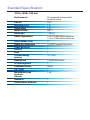
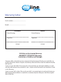
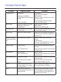
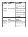
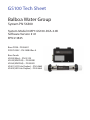
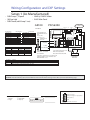
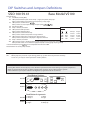
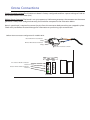
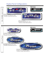
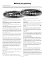
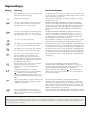
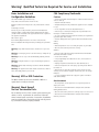
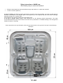
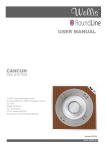
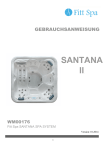
MARS USER’S GUIDE WM00175 MARS SPA User’s manual _____________________ Version: 02.2014 Standard Specification: 2130×1600×780 mm Shell material Persons Reclining places Sitting place Water volume Net weight Power requirement Total number of jets Hydro massage pump Ozone generator Diverter Filter Chromotherapy lighting Heating unit Air inlet regulator Computer control 3/4” Drain Maintenance-free Synthetic Cabinet Headrests Thermo cover with lock PU reinforced antimicrobial acrylic (6,3 mm) 3 Prs 2 Prs 1 Prs 660 l ~250 kg 1×25 A (230V/50Hz) optimum 1×16 A (230V/50Hz) minimum 37 1×2 HP 2 speed (230V/50Hz) 1 1 1 12×1 LED 1 (3kW/230V/50Hz) 3 VL260 1 1 set 2 1 Warranty letter Serial number:............................................... Model: ............................................................. Distributor Retailer Date of buying: Date of buying: Signature: Signature: (stamp) (stamp) 2014 MyLine Spa Limited Warranty WARRANTY FOR EXPORT Warranty; Limitations of Liability and Damages. Company offers a limited warranty comprised of replacement of faulty parts and offers no reimbursement for labour of repairs outside any abnormal failure rates to be determined by both parties. 5 years on spa shell: WELLIS warrants the structure of the spa shell against defects in workmanship and material for a period of 5 years, subject to the limitations and conditions listed in this Warranty. 3 years on spa shell surface: The acrylic spa shell is warranted against cracking, blistering or delaminating due to defects in materials or workmanship for three years from the original date of delivery. 2 years on spa plumbing: Spa fittings and plumbing are warranted against leaks due to defects in materials or workmanship for two years from the original date of delivery. There is no labour coverage on internal jet parts replacement, cleaning or adjusting. 2 years on standard and optional spa equipment – Balboa Control Systems, Jet Pump(s), Laing Circulation Pump, Heater, Wi-Fi module, IR receiver: The spa equipment systems are warranted against failure due to defects in materials or workmanship for two years from the date of delivery. Fuses, bulbs, and seals are not covered. 2 years on Pulsar hydrotherapy system: The factory installed Pulsar hydrotherapy systems are warranted against failure due to defects in materials or workmanship for one year from the original date of delivery. 2 years on spa cabinets/skirts: The factory installed spa cabinets/skirts are warranted against failure due to defects in materials or workmanship for one year from the original date of delivery. 2 years on ozone generator: The ozone generator is warranted against failure due to defects in materials or workmanship for one year from the original date of delivery. 2 years on audio system components: The factory installed audio components (i.e. power supply, speakers, wires, etc.) are warranted against failure due to defects in materials or workmanship for one year from the original date of delivery. There is no in-field labour service on these items. 2 years on LED lights: The factory installed LED lights are warranted against failure due to defects in materials or workmanship for one year from the original date of delivery. 2 years on UV-C sanitizer lamp: The factory installed UV-C sanitizer lamps are warranted against failure due to defects in materials or workmanship for one year from the original date of delivery. 2 years on I.S.I.S. water disinfection system: The factory installed I.S.I.S. water disinfection systems are warranted against failure due to defects in materials or workmanship for one year from the original date of delivery. 1 year on blower: The blower is warranted against failure due to defects in materials or workmanship for one year from the original date of delivery. 1 year on thermo cover: The thermo cover is warranted against failure due to defects in materials or workmanship for one year from the original date of delivery. 1 year on WELLIS Spa Umbrella: The factory installed WELLIS Spa Umbrellas are warranted against failure due to defects in materials or workmanship for one year from the original date of delivery. 1 year on LCD TV system: The factory installed LCD TV systems are warranted against failure due to defects in materials or workmanship for one year from the original date of delivery. 90 days on skimmer house: Skimmer houses are subject to water chemistry variation and are warranted for ninety days from the original date of delivery. NO warranty on filters, spa pillows and skimmer house tops. WARRANTY PERFORMANCE 1. This warranty does not cover cleaning or adjusting spa or for customer error in following correct procedures. 2. WELLIS Magyarország Kft. reserves the right to substitute a spa or component of equivalent value, either new or factory reconditioned and any such repair or replacement shall assume as its warranty only the remaining portion of the warranty on the original product. 3. WELLIS Magyarország Kft. is not liable for any costs associated with in-ground, in-deck, or in-home installations or removal. Costs associated with installations other than standard residential portable spa use will be the sole responsibility of the spa owner. The spa owner is responsible for any freight and/or delivery and set up charges for a replacement spa. 4. The radio reception is not covered under warranty due to the following: The radio signal reception may be impaired by the positioning of the spa next to or near structures, high power lines, main power lines or metallic towers. The signal reception may be impaired if the spa is located near hills or it is in a valley or simply outside the broadcasting range of the radio stations. The position of the spa and radio may be “out of phase with the bandwidth” or the radio frequency. External signal reception assistance may be required and is not part of this warranty. 5. WELLIS Magyarország Kft. shall not be liable for any incidental or consequential damages for breach of any expressed or implied warranty, breach of contract, negligence, strict liability, or any other legal theory related to this product. All consequential expenses including loss of use, damages, or contingent liabilities arising out of any alleged deficiencies of the spa are specifically excluded from this warranty. 6. Warranty coverage is only extended to the original buyer. Spas purchased from anyone other than a current WELLIS Spas Authorized Dealer are specifically excluded from any warranty coverage. To obtain warranty service, please notify your WELLIS Spas Authorized Dealer in writing within 14 days of the problem (with problem details, original proof of purchase). 7. The Authorized Dealer will repair or replace any component found defective under the terms of this warranty – and permitted by WELLIS Magyarország Kft. Travelling expenses may apply outside of every European cities. 8. If the Authorized Dealer doesn`t supply the customer with proper service, please notify WELLIS Magyarország Kft. by mail within 10 days of the problem. 9. Electrical connection: All electrical connections are required to be done by a qualified electrician solely. The spa has to be connected to separate current circuit equipped with suitable power switch and life safety relay. Omission of these electrical conditions/requirements entails immediate loss of the warranty. 10. Water connection: All water connections are required to be done by a qualified plumber solely. If the spa is placed indoor make allowances for the following special requirements: The water accumulates around the spa so the socket cover has to be in possession of a suitable drainage. This arrangement hinders the water in collecting. 11. WELLIS Magyarország Kft. offers a limited warranty as described in the Warranty Letter. 12. Warranty claim is enforceable with this warrant letter. Irregular establishing of this warrant letter doesn`t affect to the validity of warranty obligation. If customer doesn`t get this warrant letter from the Authorized Dealer, it doesn`t affect to the validity of warranty obligation. SPA WARRANTY COVERAGE WILL BE VOID UNDER THE FOLLOWING CONDITIONS 1. If damages caused by inefficient maintenance of water and/or chemical dosage. Terms of water hardness (limits): between 6-10 German degrees. 2. If the spa surface or equipment has been damaged or discoloured as a result of improper water chemistry maintenance, including sanitizers such as trichlor type chlorine, calcium hypochlorite, sodium hypochlorite, and any other chemicals or a chemical dispenser that may rest on the spa surface. Some household cleaners can damage the spa shell or equipment and will void this warranty completely. Use only products that are recommended for spas. 3. If damage to the spa has resulted from an Act of God, force majeure, moving of the spa, improper installation, unstable power conditions, customer negligence, customer abuse, weather and sunlight damage or damage caused in shipment. 4. If damage to the spa has resulted from operation outside – temperature exceed 45°C. 5. If the spa has been subjected to any alterations, after-market product installations, misuses, abuses, or if any repairs are attempted by anyone other than its authorised dealers. 6. If damage to the spa has resulted from improper use of thermo cover. 7. If damage to the spa has resulted from clogged, dirty and/or clogged filter. The spa warranty will be void if the owner does not follow all the instructions in the owner’s manual regarding the proper use and care of the spa. Warranty doesn`t apply to filters! 8. If damage to the spa has resulted from improper electrical installation, voltage drop, peak voltage and/or operation is outside the pale of + / - 10% voltage range. Electrical conditions: For electrical installation it is required to build a 30mA circuit breaker (life safety relay), which is just connected to the spa (not allowed to connect any other devices). This 30 mA circuit breaker is not permitted to be installed in the same place as the spa. Required to install IEC, RCCB system in spa`s common surroundings. Length of cable is 3 meters at the place of spa installed. It is obligatory to observe all information, details and requirements which are in the product`s installation diagram regarding electricity demand and drain installation. These information can be found in the user manual, or able to download from www. wellis.eu. If you didn`t get the document from your dealer, please contact support@ wellis.eu. If damage to the spa has resulted from debris in jets (i.e. sand, dirty calcium, leaves etc.). 9. Warranty doesn`t extend to the waste water manifold (drain hose), pillows, filters, bulbs and/or pump sealing. LIMITATIONS The Warranty expressions specified excludes any other implied or oral undertakings. Purchasers also have current rights under statute which will be respected by WELLIS Magyarország Kft. After a period of 12 months, for the purpose of assessing WELLIS Magyarország Kft. liability, all aspects covered by this Warranty will be treated on a pro-rata basis. WELLIS Magyarország Kft. or its agents will not be liable for any incidental or consequential loss or injury. Nor will WELLIS Magyarország Kft. be liable for costs associated with but not limited to building alterations or finishes and under no circumstances will be liable for greater expense than the amount paid for the product. THE SPA OWNER MUST DO EVERYTHING STATED IN THE SPA OWNERS MANUAL AND WARRANTY LETTER TO SAFEGUARD AND MAINTAIN THE SPA! MANUFACTURER OF YOUR SPA: WELLIS Magyarország Kft. Registered:....................................31/C, Budaörsi út, H-1118 Budapest, Hungary Central premise:..........................hrsz: 0417, Mánteleki út, H-2371 Dabas, Hungary AUTHORIZED DEALER OF YOUR SPA Company in charge of your spa Spa Industries Europe Company name:......................................................................................................................................................... Registered: ................................................................................................................................................................... Central premise: ....................................................................................................................................................... Place of complaint: ................................................................................................................................................ E-mail address: .......................................................................................................................................................... Website:...................................................................................................................................................................... http://www.spa-industries.eu/ Phone number: ......................................................................................................................................................... Fax: .................................................................................................................................................................................. Person in charge of installation: .......................................................................................................................... Date of installation: ................................................................................................................................................. Service-work The announcement date of damage: _____________________________ Date of received goods/parts for repair: _____________________________ Date of the return of repaired goods/parts: _____________________________ Date of site service: _____________________________ Improved error: _____________________________ Mode of repair: _____________________________ Failed component: _____________________________ New deadline for the warranty: _____________________________ The announcement date of damage: _____________________________ Date of received goods/parts for repair: _____________________________ Date of the return of repaired goods/parts: _____________________________ Date of site service: _____________________________ Improved error: _____________________________ Mode of repair: _____________________________ Failed component: _____________________________ New deadline for the warranty: _____________________________ The announcement date of damage: _____________________________ Date of received goods/parts for repair: _____________________________ Date of the return of repaired goods/parts: _____________________________ Date of site service: _____________________________ Improved error: _____________________________ Mode of repair: _____________________________ Failed component: _____________________________ New deadline for the warranty: _____________________________ The announcement date of damage: _____________________________ Date of received goods/parts for repair: _____________________________ Date of the return of repaired goods/parts: _____________________________ Date of site service: _____________________________ Improved error: _____________________________ Mode of repair: _____________________________ Failed component: _____________________________ New deadline for the warranty: _____________________________ A stamp B stamp C stamp D stamp SAFETy INSTRUCTIONS ATTENTION: PLEASE READ CAREFULLY AND FOLLOW THE INSTRUCTIONS AVOIDING THE RISK OF INJURy OF CHILDREN 1. In order to reduce the risk of injury to children, do not allow children to use this spaalone unless they are carefully supervised at all the times. 2. Lower water temperatures arerecommended for young children. Please test the water temperature with yourhands before allowing children to get into the spa, and make sure it iscomfortable for children’s usage. 3. Remember that wet surfaces can be slippery, please remind children to be careful when entering or exiting the spa. 4. Don’t permit children to climb onto the spa cover. AVOIDING THE RISK OF INJURy OF BATHERS 1. In order to reducing the risk of injury to bathers, do not remove or lose anysuction fittings. Never operate spa if the suction fitting are broken or missing. 2. Remember that wet surfaces can be very slippery. Take care of a danger ofslipping and falling when entering or exiting the spa. 3. For the sake of health, people with infectious diseases should not be allowed touse the spa. 4. Keep any loose articles of clothing or hanging jewelry away from rotating jets orother moving components. 5. The use of drugs, alcohol or medicine before or during spa use may lead to unconsciousness with the possibility of drowning. Persons using medicines shouldconsult a physician before using spa; some medicine may cause a user to becomedrowsy. While other medicine may affect heart beating, blood pressure changing and circulation problem. 6. Pregnant women should consult a doctor before using the spa. AVOIDING TNE RISK OF ELECTROCUTION 1. Test the ground fault circuit interrupters before use. Must always to be connectedto a circuit protected by a ground fault interrupt. 2. Check the power cables cord, a damaged power cord may result in death, or seriouspersonal injury due to electrocution. Do not use the spa with damaged power cable, change that immediately before using and need to disconnect the spa from power supply. 3. Do not permit any electrical appliances, such as a light, telephone, radio, or television within 1,5m of a spa. Keep a safe distance from spa, because this failure may result indeath, or serious injury due to electrocuting if the appliance should fallinto the spa. 4. Install your spa in such a way that drainage is away from the electricalcompartment and from all electrical components. 5. Disconnect the spa from the power supply before servicing the electricalcomponents. NOTICE: your spa is anequippedwith two/three massage pumps that allow you tooperate eachpart of the jet system separately or all valves simultaneously. Do not connect power to an empty spa. Otherwise the components such ascontroller, heater, circulation pump, and other systems could be damaged. INSTALLATION INSTRUCTIONS SITE PREPARATION 1. INDOOR/BASEMENT INSTALLATION If you take it place your spa indoors, be aware of some special requirements. Water willaccumulate around the spa, so the flooring materials must provide a good grip whenwet proper drainage is essential to prevent a build-up of water around the spa. When building a new room for the spa it is recommended that a floor drain isinstalled. The humidity will naturally increase with the spa installed water may getinto woodwork and produce rot, mildew or otherproblems. Check for airborne moisture’s effects on exposed wood, paper, etc in theroom .To minimize these effects, it is best to provide plenty of ventilation to the spa area. 2. OUTROOR AND PATIO INSTALLATION It is important that you have solid foundation to support the new spa when youinstall it .Tobe certain your deck or foundation can support your spa. You mustknow the deck maximum load capacity. Consult a qualified building contractor orstructural engineer. To find the weight of your spa, its contents and occupants, please refer to the spa specification chart. This weight per square foot must notexceed the structure’s rated capacity: otherwise serious structural damages couldresult,if you install the spa outdoors we recommend a reinforced concrete pad a tleast four inches thick. Don’t forget to install some floor drains around your spa sothat it can take the water away during and after the heavy rain. INSTALLATION 1. 2. 3. 4. Please read and study the OWNER’S MANUAL carefully. Please finda professional people to install and setup for first time. Remove the package, and take down the new spa on the prepared foundation. Open the control box compartment under the display by loosenthe screw and then open the control box. Prepare the accordingly cooper cable(the length will be enough to connect to the power supply), with electricalplug one side and another side without plug and then take the empty side of cablefrom electrical cable. Lead the cable through the pump compartment to the channelof control box compartment.Connect the electrical cable to control box according by electrical drawing in user manual. Your spa has been thoroughly tested duringthe manufacturing process to ensure reliability. So there is a small amount of water even within some grease may have remained in the plumbing after testing, as a result,may have spotted the spa shell or the spa siding prior thedelivery so before filling spa. OPERATING INSTRUCTIONS 1. Close the drain stub and fill the spa with water After closing the drain stub, and fill up the tub with soft water to theindicated line inside of the body. If you see any leak(orflood) anywhere, stop the filling procedure until it will be fixed. 2. Power up your spa First check the main house CIRCUIT INTERRUPTORY that controls the electricto the spa are functioning properly. Then connect the spa plug to the power supply. 3. Trail open and test Your controller with a factory‘s first setup already. push the button of PUMP/JET andAIR BLOWER to make jets run for some minutes to check the operations of the jetsystem and purge any remaining air from the heating system. once the jet systemfully operational, priming of the spa is complete. Check and make sure the all aircontroller and all jets are open. Possible symptom is an AIR LOCK on the first starting or when fills up with new water. It can cause the jets to appear not work well or at all. It happens when you are filling the spa up fairly rapidly, and air can get trapped in the pipe system that goes to the suction fittings and to the jets. The water level rises up past the openings in the spa, but air becomes locked in the pipes, and then when you start the spa pump, it tries to air bubble(s) still in water, but only air is in the pipes. Sometimes the pump cannot prime itself at that point, so it just runs, but does not pump any water. Solution: 1. Open the door of pump compartment. 2. Loosen the quick disconnectfitting (white rim on the pump) in front of the pump a little. 3. Let some air get in and it will break the air lock that has developed, and then see some water start to come out. 4. Re-tighten the fitting. 5. Turn the pump on again. It will surge for a few seconds and then start to pump properly. If it still does not work, please contact a local spa professional to check it for you. CLEANING GENERAL INFORMATION: Water recirculation-filtering The basic conditions for keeping the water of the spa clean are the removal of mechanical dirt and the blending of the chemicals in the water with continuous water recirculation. In all our spa’s appliances comprising of a pump and a filter are used for this purpose. - The filter removes the dirt floating in the water or at the surface of the water. Filters with paper or textile filter medium are used in the spa. The dirt settled at the bottom of the spa is filtered out with the aid of the suction and stirring created by the massage pumps. Protecting the spa Don’t leave the spa expose to the sun without water or the cover. Exposure to direct sunlight can cause solar distress of the shell material. Use a spa cover when spa is not in use, whether it is empty or full. Try to keep your spa away from rain and snow. If possible, build a gazebo for your spa. 1. 2. 3. 4. Don’t attempt to open the electrical control box. There are no user serviceable parts inside. Drain, clean and refill your spa with fresh water on a regular schedule. Clean the filter cartridge at least once a month. Have spa users bathe before entering the spa water, showering without soap prior to enter the spa, and using only the rinse cycle when laundering your bathing suit, will help avoiding detergent and soap residue in spa water. FILTER CARTRIDGE RMOVAL AND CLEANING You spa filter cartridge can become clogged with mineral particles of calcification from hard water. Which may result in reduced water flow. We recommend to clean the filter cartridges every month. 1. Remove filter grid. 2. Unscrew filter cartridge. 3. Clean with high pressure nozzle to remove all debris that clinging the filter. 4. Soak filter in warm water and WELLIS Alga Shock to remove all body oils and grime. Never use chlorine to clean the filter! The chemical equilibrium of the water The water of the spa will be clean and clear if its chemical components are in equilibrium. 1. pH-value: The first important indicator is the pH value of the water. pH is measured in a scale between 0-14 where 7 is the neutral value. Below this level the water is acidic, above it is alkaline. The pH value of the human eye is around 7.5, below 7.2 and above 7.8 the water will sting the eyes of the bather. Experiences have shown that most problems are caused by a too high pH value. An improper value reduces the effect of the disinfectant. 2. Water hardness: Water hardness is determined by the quantity of calcium and magnesium salts dissolved in the water. Hard waters contain too much of these dissolved salts and thus, left alone, scale will form. Scales can cause significant damage both to the walls of the spa, to the piping, filter and to the heating and engineering units. In Hungary waters are medium hard. Water hardness cannot be reduced by the addition of chemicals, but the formation of scales can be prevented. 3. Disinfection: Disinfectant is the chemical that eliminates or neutralises the microorganisms (bacteria, algae, fungi, viruses) present in the water. Microorganisms are small, microscopic organisms, which cannot be detected with the naked eye and are continuously getting into the water through rain, wind and the body of the bathers. If they are not eliminated they pass from one person to the other through the water (and may cause sickness, infection). Organic matter turns the water of the spa opaque and cloudy. Most often – as we are dealing with warm water spas – bromine or active oxygen is used. 4. Frothing: Froth is the smaller-bigger agglomeration of the bubbles and colloid contaminants found on the surface of the water. It is mostly caused by the mixing of the dirt, cosmetics, body care lotions, etc. that soak out of the human skin and the chemicals. It endangers the conservation of the aesthetic appearance and cleanliness of the water. 5. Water analysers: There are several different types of water analysers, which are mostly used to measure chemical and disinfectant effect. Chemical (pH); Disinfectant (Br, O3) Tester types: - Box containing tablets and graduated measuring glass. - Litmus paper indicators in a box. Chemicals should always be loaded into the filter housing. Then proper disinfection of the spa balance, if the chemical levels are not at least 48 hours below the specified value. Even with the most accurate disinfection after 2-3 months, the water quality is no longer maintain and necessary replace the full water quantity. Then proposed a large swimming pool, shock-like disinfection. Replacing underwater light 1. Turn off the power of the spa. 2. Remove plastic panel behind where the underwater light is situated. 3. There is a plug with two wires going into the back of the light. 4. Remove this plug by turning anticlockwise. 5. Replace faulty light globe with a new one. 6. Replace parts and put the plastic panel back on. TROUBLESHOOTING Problem Probable causes Solutions Cloudy Water Dirty filters. Clean filters. Shock spa with sanitizer. Add sanitizer. Improper sanitization. Suspended particles/organic Adjust PH andl or alkalinity to recommatter. mended range. Run jet pump(s) and clean filters. Overused water. Drain and refill the spa. Water Odor Excessive organics in water. Improper sanitization. Low PH level. Shock spa with sanitizer. Add sanitizer. Adjust PH or refill the spa. Chlorine Odor Chloramines level too high. Low PH level. Shock spa with sanitizer.Adjust PH to recommended range. Musty Odor Bacteria or algae growth. Shock spa with sanitizer id problem is visible or persistent drain, clean and refill the spa. Organic build-up/ scum ring around spa Build-up of oils and dirt. Wipe off scum with clean rag-if severe. Drain the spa. Use a spa surface cleaner to remove the scum, and refill the spa. Algae Growth High PH level. Shock spa with sanitizer and adjust PH level. Shock spa with sanitizer and maintain sanitizer level. Low sanitizer level. Eye irritation Low PH level. Low sanitizer level. Ajust PH level. Shock spa with sanitizer and maintain sanitizer level. Skin irritation/rash Unsanitary water. Shock spa with sanitizer and maintain s anitizer level. Allow free chlorine level to drop below 5ppm before spa use. Free chlorine level above 5ppm. Stains Total alkalinity andl or PH too low high iron or copper in source water Adjust total alkalinity and/or PH level. Use a metal deposit inhibitor. Scale High calcium content in water-total alkalinity and PH level too high. Adjust total alkalinity and PH level. If scale requires removal, drain the spa, scrub off the scale, refill the spa and balance the water. Problem Probable causes Solutions Entire spa is inoperative. Power failure. GFCI tripped heater high-limit thermostat tripped. Check power source. Reset GFCI, call for service if not reset. Disconnect power for at least thirty second to reset heater high limit. If it will not reset check for clogged filters. If tripping continues, call for service. Spa does not heat jets and light operate (Ready, and power indicators are blinking. Integrated pressure switch open Circulation pump thermal cut-off tripped. Check for cartridge filters. Integrated pressure switch will reset when the flow of water through the heater has been retored Call for ervice if the heater trips frequently. Check for cartridge filters or are looks in plumbing Disconnected power to the spa, allow circulation pump to cool Circulation pump thermal cut off will reset when pump has cooled and power is reapplied. Call for service if circulation pump thermal cutoff trips frequently. Jets weak or surging. Spa water level too low. Filters clogged. Air regulator is closed. Jet closed. Add water. Clean filters. Open air regulator. Open the jet. Light inoperative. Light wiring or assembly is faulty. Replace light assembly. Power indicator is blinking. (Entire spa inoperative) Heater high-limit thermostat Disconnect power for at least thirty tripped. seconds to reset heater high limit. If it will not reet. Check for clogged filters if tripping continues, call for service. Ready indicator blinking. Temperature sensor problem. Disconnect power for at feast thirty second problem if blinking continues, call for service. GS100 Tech Sheet Balboa Water Group System PN 56300 System Model # MP7-GS100-DCA-3.0K Software Version # 41 EPN # 3825 Base PCBA - PN 56301 PCB VS100C - PN 24084 Rev A Base Panels VL200 (Mini) – PN 55123 VL240 (MVP240) – PN 55080 VL260 (MVP260) – PN 55081 VL401 (LCD Lite Duplex) – PN 54665 VL403 (LED Lite Duplex) – PN 54664 Basic System Features and Functions Power Requirements • 230VAC, 1~, 16A, 50Hz • 3 wires (line, neutral, ground) System Outputs Setup 1 (As Manufactured) • 230V Pump 1, 2-Speed • 230V Ozone • 10V Spa Light • 230V 3.0kW Heater PN 58202 Page 2 56300_97_B Basic System Features and Functions Any time you change a DIP Switch, other than A1, you must reset Persistent Memory for your new DIP Switch Settings changes to take effect. If you do not reset Persistent Memory, your system may function improperly. To reset Persistent Memory: • Power down by disconnecting power source from spa. • Put a jumper across J43, covering both pins. • • • • (See illustration below) Power up by connecting power source to spa. Wait until “ ” is displayed on your panel. Power down again. Remove jumper from J43 (May also move to cover 1 pin only) • Power up again. About Persistent Memory and Time of Day Retention: This system uses memory that doesn’t require a battery to store a variety of settings. What we refer to as Persistent Memory stores the filter settings, the set temperature, and the heat mode. Power Up Display Sequence Upon power up, you should see the following on the display: Three numbers in a row, which are the SSID (the System Software ID). The third display of these numbers is the Software Version, which should match the version of your system. For example, if these three numbers are , that is a VS511SZ at version 38. • Displayed next is: “ ” (indicating the system is configured for a heater between 3 and 6 kW) or “ ” (indicating the system is configured for a heater effectively* between 1 and 3 kW). ” ” should appear for all VS models running at 240VAC. ” should appear for all VS models running at 120VAC, as well as all GS models. (*A heater which is rated at 4 kW at 240VAC will function as a 1 kW heater at 120VAC.) • “ ” will appear to signal the start of Priming Mode. • At this point, the power up sequence is complete. Refer to the Reference Card for the VS or GS System model of your spa for information about how the spa operates from this point on, including how to adjust the Time of Day if using a Serial Deluxe style panel. J43 MEM RESET J6 TEST Persistent Memory is not used for Time of Day. Only models with a Serial Deluxe panel installed (VS5xxDZ and GS5xxDZ) can display the time. However, during power loss to the spa, the system will lose the correct time, and reset to 12:00 PM when power is restored. J11 J1 J7 HI/LOW J8 Wiring Configuration and DIP Settings Setup 1 (As Manufactured) • 230V Pump 1, 2-Speed • 3.0kW @ 230VAC Heater • 10V Spa Light • VL401 Main Panel • 230V Ozone (with Pump 1 Low) PN 56300 PUMP TIMEOUTS TABLE SWITCH 5 SWITCH 9 OFF OFF ON OFF OFF ON ON ON LOW SPEED 2 HOURS 2 HOURS 15 MINUTES 30 MINUTES 12VAC-A J13 ON F5 3A 250V K5 230V L1 (BRN) K3 K6 J9 HEATER J57 NEU (BLU) K2 J28 115V 115V J3 F1 20A 250V J29 J23 K4 K1 VS100C P/N 24084_A J90 J26 J7 J1 HI/LOW J8 J18 GROUND (GRN) HIGH SPEED 15 MINUTES 30 MINUTES 15 MINUTES 30 MINUTES SENSOR B GROUND - TERRE - ERDE GELB/GRUN - JAUNE/VERT YELLOW/GREEN USE COPPER CONDUCTORS ONLY. EMPLOYER UNIQUEMENT DES CONDUCTEURS DE CUIVRE. SENSOR A HEATER 3.0 KW @ 230VAC HEIZELEMENT RADIATEUR FOR SUPPLY CONNECTIONS, USE CONDUCTORS SIZED ON THE BASIS OF 60°C AMPACITY BUT RATED MINIMUM OF 90°C. LOCATION J23 J29 J20 J11 T1 J10 BONDING GROUND (INSTALLED) ALL UNUSED SWITCHES SHOULD BE OFF LIGHT AUX F J22 PUMP 1 TORQUE RANGE FOR MAIN TERMINAL BLOCK (TB1): 27-30 IN. LBS. (31.1-34.5 kg cm) TEST MODE ON* P1, LT, TEMP DOWN, TEMP UP MINI PANEL N/A MUST BE OFF SEE PUMP TABLE 50HZ OPERATION STANDARD MODE ONLY DEGREES CELSIUS SEE PUMP TABLE LOW AMP - NO HEAT W/P1 HI J27 *SWITCH 1 IS NORMALLY OFF 1 2 3 4 5 6 7 8 9 10 TB1 TEST MODE OFF* UNUSED, P1, TEMP, LIGHT DUPLEX PANEL N/A MUST BE OFF SEE PUMP TABLE 60HZ OPERATION STD, ECON, SLEEP ALLOWED DEGREES FAHRENHEIT SEE PUMP TABLE HIGH AMP - HEAT W/P1 HI J12 ON POSITION F2 0.125A 250V DIP SWITCH # J20 J43 MEM RESET J6 TEST 12-10-12 OFF POSITION CONTROL PANEL TO J1 12VAC-B OZONE GS100 DEVICE NETZSTROMVERSORGUNG 2-GESCHW.-PUMPE 1 ALIMENTATION POMPE 1 A 2 VITESSES 2-SPEED PUMP 1 OZONGENERATOR GENERATOROZONE OZONE GENERATOR BELEUCHTUNG ECLAIRAGE BAIN HYDRO SPA LIGHT WARNING: Main Power to system should be turned OFF BEFORE adjusting DIP switches. WARNING: Persistent Memory (J43) must be RESET to allow new DIP switch settings to take effect. (See Persistent Memory page) Board Connector Key , g Panel Button Positions Panel Button Assignments 1=Unused 1=Pump 1 2=Pump 1 2=Light 3=Temp Down 4=Light Up 4=Temp p 1 2 3 4 1 4 2 3 1 Typically Line voltage 2 Typically Line voltage for 2-speed pumps 3 Neutral (Common) 4 Ground Note flat sides in connector DIP Switches and Jumpers Definitions SSID 100 59 41 Base Model VS100 DIP Switch Key A1 Test Mode (normally OFF) A2 “ON” position: Button layout will be: Pump 1, Light, Temp Down, Temp Up * “OFF” position: Button layout will be: Unused, Pump 1, Temp, Light A3 “ON” position: use Mini Panel * “OFF” position: use Lite Duplex or Digital Duplex panel A4 N/A (must be OFF) A5 Pump 1 timeout, see Table 1 Table 1 Pump 1 Timeouts A6 “ON” position: 50Hz operation “OFF” position: 60Hz operation A5 A9 Low-spd Hi-spd A7 “ON” position: Standard mode only OFF OFF 2 hours 15 min “OFF” position: Std/Ecn/Sleep mode changes allowed ON OFF 2 hours 30 min A8 “ON” position: temperature is displayed in degrees Celsius OFF ON 15 min 15 min “OFF” position: temperature is displayed in degrees Fahrenheit ON ON 30 min 30 min A9 Pump 1 timeout, see Table 1 A10 “ON” position: heater is disabled while the high-speed pump is running (low amperage mode) “OFF” position: heater can run while the high-speed pump is running (high amperage mode) are not compatible when A2 or A3 is ON. * Panels with button layout Note: No blower or second pump available. Jumper Key J43 When jumper is placed on 2 pins during power-up, system will reset persistent memory. Leave on 1 pin only to enable persistent memory feature. WARNING: • Setting DIP switches incorrectly may cause abnormal system behavior and/or damage to system components. • Refer to Switchbank illustration on Wiring Configuration page for correct settings for this system. • Contact Balboa if you require additional configuration pages added to this tech sheet. Panel Button Positions A3: OFF 1 2 A3:ON 3 1 2 4 3 4 Panel Button Assignments 1=Unused 3=Temp 4=Light 1=Pump 1 2=Light 3=Temp Down 4=Temp Up A2: OFF 2=Pump 1 A2:ON 1 4 2 3 Ozone Connections Ozone Connector Voltage:The VS100 circuit board is factory configured to deliver a preset voltage of 120V to the on-board ozone connector (J29). Balboa Ozone Generator:The board is set up to operate a 120V ozone generator; the connector on the ozone generator is likely to be configured correctly, but should be compared to the illustration below. Note: A special tool is required to remove the pins from the connector body once they are snapped in place. Check with your Balboa Account Manager for information on purchasing a pin-removal tool. Balboa Ozone connector configuration for 230VAC 50Hz: L Black or Brown Line Conductor Empty White or Blue Neutral Conductor Empty N Flat sides of sockets as shown F1 20A 250V J29 J23 PUMP 1 Line - Black or Brown conductor Not used Neutral - White or Blue conductor Not used OZONE K4 K1 SETUP (AS MANUFACTURED) Duplex Panel Configurations Heat Jets Light Cool DIP switch A3 must be OFF Warm VL403 (Lite Digital) PN 54664 with Overlay PN 11884 • Connects to Main Panel terminal J1 Heat Jets Light Cool Warm VL401 (Lite Digital) PN 54665 with Overlay PN 11885 • Connects to Main Panel terminal J1 Jets Light Cool Warm OPTIONAL PANELS DIP switch A3 must be ON VL200 (Mini Panel) PN 55123 with Overlay PN 11852 • Connects to Main Panel terminal J1 Jets Light Cool Warm VL240 (MVP240) PN 55080 with Overlay PN 11745 • Connects to Main Panel terminal J1 VL260 (MVP260) PN 55081 with Overlay PN 11746 • Connects to Main Panel terminal J1 Jets Light Cool Warm MVP260 Kurzanleitung Betrieb ohne Umwälzpumpe Erstmaliges Einschalten Der Whirlpool läuft beim erstmaligen Einschalten im Spülmodus (angezeigt durch „ ”). Ausführliche Anweisungen zum Einschalten und Durchspülen der Pumpe finden Sie in der Installationsanleitung des M7-Bedienungssystems. Der Spülmodus dauert bis zu 5 Minuten, danach wird der Whirlpool aufgeheizt und die Wassertemperatur im Standardmodus beibehalten. Jets Blower Jets Temp Jets Temp Light Light Temperatureinstellung (26 °C - 40 °C / 80 °F - 104 °F) Die Temperatur ist beim erstmaligen Einschalten auf 37 °C (100 °F) eingestellt. Die zuletzt gemessene Temperatur wird konstant in der LCD angezeigt. Bitte beachten, dass die zuletzt gemessene Wassertemperatur nur dann genau angezeigt wird, wenn die Pumpe mindestens 2 Minuten lang gelaufen ist. Zum Anzeigen der eingestellten Temperatur die Taste „Temp“ oder „Set“ einmal drücken. Zum Ändern der Temperatur Taste erneut drücken, bevor die LCD zu blinken aufhört. Jedes erneute Drücken des „Temp“ und „Set“ Feldes erhöht oder erniedrigt die Temperatur entspreched. Wird die entgegengesetzte Richtung gewünscht, Feld loslassen und Anzeige zur derzeitigen Wassertemperatur zurückkehren lassen. Feld drücken um die eingestellte Temperatur anzuzeigen und noch einmal drücken, um eine Richtungsänderung der Temperatur herbeizuführen. Nach drei Sekunden zeigt die LCD automatisch die zuletzt gemessene Whirlpool-Temperatur an. Hinweis: Sollte Ihr System kein Gebläse aufweisen, kann eine andere Konsole mit seperaten „Up“ und „Down“ Tasten anstatt „Set“ oder „Temp“ verwendert werden. Einfach „Up“ oder „Down“ drücken, wo ein Drücken von „Temp“ oder „Set“ verlangt wird. (Den „Richtungswechsel-Paragraph“ ignorieren) Jets Durch einmaliges Drücken der Taste „Jets“ wird Pumpe 1 mit langsamer Geschwindigkeit aktiviert, nach dem erneuten Drücken mit höherer Geschwindigkeit. Die Taste „Jets“ ein weiteres Mal drücken, um die Pumpe auszuschalten. Wenn die Pumpe eingeschaltet bleibt, schaltet sich die langsame Pumpgeschwindigkeit nach 4 Stunden automatisch aus, die schnelle Pumpgeschwindigkeit nach 15 Minuten. Die Pumpe läuft langsam, wenn das Gebläse an ist. Sie kann sich außerdem für mindestens 2 Minuten alle 30 Minuten einschalten, um die Whirlpooltemperatur zu messen und je nach Modus und Bedarf zu erhöhen. Nach der automatischen Aktivierung der langsamen Pumpgeschwindigkeit kann die Pumpe nicht per Tastendruck ausgeschaltet werden, die schnelle Pumpgeschwindigkeit lässt sich jedoch starten. Gebläse (optional) Diese Taste zum Ein- und Ausschalten des Gebläses verwenden. Wird das Gebläse angelassen, schaltet es sich nach 15 Minuten automatisch aus. Jets 2 (optional) Sollte in Ihrem System Pumpe 2 anstatt des Gebläses installiert sein, verhält sich diese genau wie ein Gebläse. Beleuchtung Zum Ein- und Ausschalten der Whirlpool-Beleuchtung die Taste „Light“ drücken. Wenn die Beleuchtung nicht manuell ausgeschaltet wird, schaltet sie sich nach 4 Stunden automatisch aus. Modus Zum Ändern des Modus die Tasten „Temp“ oder „Set“ und dann „Light“ drücken. Standardmodus Bei diesem Modus wird die gewünschte Temperatur beibehalten. Bitte beachten, dass die zuletzt gemessene Wassertemperatur nur dann genau angezeigt wird, wenn die Pumpe mindestens 2 Minuten lang gelaufen ist. Beim Umschalten auf Standardmodus wird kurz „ “ angezeigt. Sparmodus Bei diesem Modus wird das Wasser nur während der Filterzyklen auf die Solltemperatur aufgeheizt. „ “ wird konstant angezeigt, wenn die Temperatur noch nicht aktuell ist. Nach dem Erreichen der aktuellen Temperatur wird dieses Symbol abwechselnd mit der Temperatur angezeigt. Schlafmodus Bei diesem Modus wird das Wasser nur während der Filterzyklen auf ±10 °C / 20 °F der Solltemperatur aufgeheizt. „ “ wird konstant angezeigt, wenn die Temperatur noch nicht aktuell ist. Nach dem Erreichen der aktuellen Temperatur wird dieses Symbol abwechselnd mit der Temperatur angezeigt. Voreingestellte Filterzyklen Der erste Filterzyklus beginnt 6 Minuten nach dem Einschalten des Systems. Der zweite Filterzyklus beginnt 12 Stunden später. Die Filterdauer ist auf 2, 4, 6, 8 Stunden oder kontinuierlich (angezeigt durch „ “) programmierbar. Die vorgegebene Filterzeit beträgt 2 Stunden. Zum Programmieren „Temp“ oder „Set“ drücken, dann „Jets“. Zum Einstellen „Temp“ oder „Set“ drücken. Zum Verlassen des Programmiermodus die Taste „Jets“ drücken. Zu Beginn jedes Filterzyklus wird der Whirlpool von Pumpe fünf Minuten, und vom Sprudelgebläse 30 Sekunden lang durchgespült. Die Pumpe läuft während des Filtervorgangs mit langsamer Geschwindigkeit, und der Ozonsterilisator (falls installiert) wird eingeschaltet. Frostschutz Wenn die Sensoren im Heizelement einen Temperaturabfall auf unter 6,7 °C / 44 °F erfassen, schalten sich Pumpe und Gebläse automatisch ein und sorgen für Frostschutz. Das System bleibt noch 4 Minuten länger eingeschaltet, wenn die Sensoren eine Wassertemperatur von mindestens 7,2 °C / 45 °F messen. In kälteren Klimazonen kann wahlweise ein zusätzlicher Frostschutzsensor eingesetzt werden, der über die Empfindlichkeit der Standardsensoren hinausgeht. Der Zusatzfrostschutz funktioniert ähnlich, außer dass die Temperaturgrenze vom Regler bestimmt wird und keine 4-minütige Ausschaltverzögerung erfolgt. Ihr Händler erteilt Ihnen hierzu gerne weitere Auskünfte. (nächste Seite) Diagnosemeldungen Meldung Bedeutung Erforderliche Maßnahme Keine Meldung angezeigt. Die Stromzufuhr zum Whirlpool wurde unterbrochen. Die Bedienungskonsole wird ausgeschaltet, bis die Stromversorgung wieder hergestellt ist. Die Whirlpool-Einstellungen bleiben bis zum nächsten Einschalten gespeichert. Nachdem die Umwälzpumpe zwei Minuten gelaufen ist, wird die Temperatur angezeigt. NICHT INS WASSER STEIGEN! Die Whirlpool-Abdeckung entfernen und das Wasser abkühlen lassen. Nach dem Abkühlen des Heizelements das System durch Drücken einer beliebigen Taste zurückstellen. Wenn sich der Whirlpool nicht zurückstellt, die Stromzufuhr unterbrechen und den Händler oder Kundendienst anrufen. NICHT INS WASSER STEIGEN! Die Whirlpool-Abdeckung entfernen und das Wasser abkühlen lassen. Bei 42 °C /107 °F müsste sich der Whirlpool automatisch zurückstellen. Wenn sich der Whirlpool nicht zurückstellt, die Stromzufuhr unterbrechen und den Händler oder Kundendienst anrufen. Keine Maßnahme erforderlich. Die Pumpe und das Gebläse werden ohne Rücksicht auf den Whirlpool-Status automatisch aktiviert. Wenn das Problem weiter besteht, den Händler oder Kundendienst verständigen. (Erscheint ggf. vorübergehend bei Überhitzung und verschwindet wieder, nachdem sich das Heizelement abgekühlt hat.) Wenn das Problem weiter besteht, den Händler oder Kundendienst verständigen. (Erscheint ggf. vorübergehend bei Überhitzung und verschwindet wieder, nachdem sich das Heizelement abgekühlt hat.) Wenn das Problem weiter besteht, den Händler oder Kundendienst verständigen. Temperatur nicht bekannt. „Overheat“ (Überhitzung) - Der Whirlpool hat sich ausgeschaltet. Einer der Sensoren hat am Heizelement 48 °C/ 118 °F gemessen. „Overheat“ (Überhitzung) - Der Whirlpool hat sich ausgeschaltet. Einer der Sensoren hat eine Wassertemperatur von 43 °C / 110 °F gemessen. „Ice“ (Eis) - Es besteht Frostgefahr. Der Whirlpool ist ausgeschaltet. Der an Buchse „A“ angeschlossene Sensor funktioniert nicht. Der Whirlpool ist ausgeschaltet. Der an Buchse „B“ angeschlossene Sensor funktioniert nicht. Die Sensoren sind nicht im Gleichgewicht. Falls diese Meldung abwechselnd mit der Wassertemperatur angezeigt wird, handelt es sich möglicherweise um einen vorübergehenden Zustand. Wenn diese Meldung allein blinkt, ist der Whirlpool ausgeschaltet. Zwischen den Sensoren wurde ein beträchtlicher Temperaturunterschied gemessen, was möglicherweise auf ein Strömungsproblem hinweist. Andauernde Probleme mit zu schwacher Strömung. (Wird angezeigt, wenn die Meldung „ “ innerhalb von 24 Stunden fünfmal erscheint.) Die Heizung ist ausgeschaltet, doch die anderen Whirlpool-Funktionen laufen normal weiter. Nicht genügend Wasser, schwache Strömung oder Luftblasen im Heizelement. Whirpool wird für 15 Minuten ausgeschaltet. Nicht genügend Wasser im Heizelement gemessen. (Wird angezeigt, wenn die Meldung „ “ zum dritten Mal erscheint.) Der Whirlpool ist ausgeschaltet. Den Wasserstand im Whirlpool prüfen. Bei Bedarf Wasser nachfüllen. Wenn genügend Wasser vorhanden ist, sicherstellen, dass die Pumpen durchgespült wurden. Wenn das Problem weiter besteht, den Händler oder Kundendienst verständigen. Gleiches Vorgehen wie bei Meldung „ ”. Die Heizfunktion des Whirlpools stellt sich nicht automatisch neu ein. Zum Aktivieren beliebige Taste drücken. Den Wasserstand im Whirlpool prüfen. Bei Bedarf Wasser nachfüllen. Wenn genügend Wasser vorhanden ist, sicherstellen, dass die Pumpen durchgespült wurden. Zum Rückstellen beliebige Taste drücken, automatisches Rückstellen erfolgt 15 Minuten nach Erscheinen dieser Anzeige. Wenn das Problem weiter besteht, den Händler oder Kundendienst verständigen. Gleiches Vorgehen wie bei Meldung „ “. Der Whirlpool stellt sich nicht automatisch zurück; zum Rückstellen beliebige Taste drücken. Achtung! Stromschlaggefahr! Keine vom Benutzer wartbaren Teile. Nicht versuchen, das Bedienungssystem selbst zu reparieren. Den Händler oder Kundendienst verständigen. Sämtliche Anschlusshinweise in der Bedienungsanleitung beachten. Die Installation darf nur von einem zugelassenen Elektriker vorgenommen werden, und alle Erdungsanschlüsse sind ordnungsgemäß zu installieren. Warning! Qualified Technician Required for Service and Installation Basic Installation and Configuration Guidelines Use minimum 6AWG copper conductors only. Torque field connections between 21 and 23 in lbs. Readily accessible disconnecting means to be provided at time of installation. Permanently connected. Connect only to a circuit protected by a Class A Ground Fault Circuit Interrupter (GFCI) or Residual Current Device (RCD) mounted at least 5’ (1.52M) from the inside walls of the spa/hot tub and in line of sight from the equipment compartment. CSA enclosure: Type 2 CSA Compliance/Conformité Caution: s4ESTTHEGROUNDFAULTCIRCUITINTERRUPTERORRESIDUALCURRENTDEVICEBEFORE each use of the spa. s2EADTHEINSTRUCTIONMANUAL s!DEQUATEDRAINAGEMUSTBEPROVIDEDIFTHEEQUIPMENTISTOBEINSTALLED in a pit. s&ORUSEONLYWITHINANENCLOSURERATED#3!%NCLOSURE s#ONNECTONLYTOACIRCUITPROTECTEDBYA#LASS!GROUNDFAULTCIRCUIT interrupter or residual current device. s4OENSURECONTINUEDPROTECTIONAGAINSTSHOCKHAZARDUSEONLYIDENTICAL replacement parts when servicing. Refer to Wiring Diagram inside the cover of the control enclosure. s)NSTALLASUITABLYRATEDSUCTIONGUARDTOMATCHTHEMAXIMUMmOWRATE marked. Refer to Installation and Safety Instructions provided by the spa manufacturer. Warning: s7ATERTEMPERATUREINEXCESSOFª#MAYBEINJURIOUSTOYOURHEALTH Warning: People with infectious diseases should not use a spa or hot s$ISCONNECTTHEELECTRICALPOWERBEFORESERVICING tub. Attention: Warning: To avoid injury, exercise care when entering or exiting the spa or hot tub. s4OUJOURSVERIlERLEFlCACITEDUDISJONCTEURDIFFERENTIELAVANTDUTILISER differentiel avant d’utiliser le bain. Warning: Do not use a spa or hot tub immediately following strenuous s,IRELANOTICETECHNIQUE exercise s,ORSQUELAPPAREILLAGEESTINSTALLEDANSUNEFOSSEONDOITASSURERUN drainage adequat. Warning: Prolonged immersion in a spa or hot tub may be injurious to your health Warning: Maintain water chemistry in accordance with the Manufacturers instructions. Warning: The equipment and controls shall be located not less than 1.5 meters horizontally from the spa or hot tub. s%MPLOYERUNIQUEMENTALINTERIEURDUNECLOTURE#3!%NCLOSURE s#ONNECTERUNIQUEMENTAUNCIRCUITPROTEGEPARUNDISJONCTEURDIFFERENtiel de Class A. s!lNDASSURERUNEPROTECTIONPERMANENTECONTRELEDANGERDESHOCK electrique, lors de l’entretien employer seulement des pieces de rechange identiques. Warning! GFCI or RCD Protection. s,ESPRISESDASPIRATIONDOIVENTETREEQUIPEESDEGRILLESCONVENANTAU debit maximal indique. The Owner should test and reset the GFCI or RCD on a regular basis to verify its function. Avertissement: s$ESTEMPERATURESDELEAUSUPERIEURESAª#PEUVENTPRESENTERUN danger pour la sante. Warning! Shock Hazard! No User Serviceable Parts. Do not attempt service of this control system. Contact your dealer or service organization for assistance. Follow all owner’s manual power connection instructions. Installation must be performed by a licensed electrician and all grounding connections must be properly installed. s$ECONNECTERDUCIRCUITDALIMENTATIONELECTRIQUEAVANTELENTRETIEN Warning/Advertissement: s$ISCONNECTTHEELECTRICPOWERBEFORESERVICING+EEPACCESSDOORCLOSED s$ECONNECTERDUCIRCUITDALIMENTATIONELECTRIQUEAVANTLENTRETIEN Garder la porte fermer. Piping instructions of MARS spa 30mA safety relay is need to be installed! E: Electric hole (500mm) to terminal facilities through spa cabinet. 3 m cabels are required! L: Drain connector (400 mm) In case of sinking just allowed to sinking part which is under the spa`s acrylic-flange. You have to make safe the diversion of inlet water in the deepest point of the inspection pit. The inspection pit has to be aired accordingly (proposal: building in an extractor fan). The inspection pit`s minimum width is 60 cm around the spa. If the spa is placed indoor please make allowances for the following special requirements: The water accumulates around the spa so the socket cover has to be in possession of a suitable drainage. This arrangement hinders the water in collecting. Given sizes above are only information, there may be variant sizes on the grounds of the spa`s manufacturing technique.