1
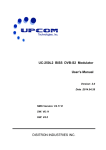
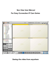
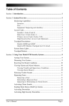
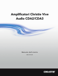
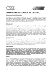
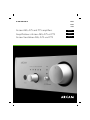
HANDBOOK
A65
A75
P75
Arcam A65, A75 and P75 amplifiers
Amplificateurs Arcam A65, A75 et P75
Arcam-Verstärker A65, A75 und P75
E nglis h
Fra nça is
D eut s ch
Safety guidelines
Safety instructions
10. Power-cord protection
This product is designed and manufactured to meet strict
quality and safety standards. However, you should be aware of
the following installation and operation precautions:
Power supply cords should be routed so that they are not likely
to be walked on or pinched by items placed upon or against
them, paying particular attention to cords and plugs, and the
point where they exit from the appliance.
1. Take heed of warnings and instructions
You should read all the safety and operating instructions
before operating this appliance. Retain this handbook for future
reference and adhere to all warnings in the handbook or on
the appliance.
2. Water and moisture
The presence of electricity near water can be dangerous. Do
not use the appliance near water – for example next to a
bathtub, washbowl, kitchen sink, in a wet basement or near a
swimming pool, etc.
3. Object or liquid entry
Take care that objects do not fall and liquids are not spilled into
the enclosure through any openings. Liquid filled objects such
as vases should not be placed on the equipment.
4. Ventilation
Do not place the equipment on a bed, sofa, rug or similar
soft surface, or in an enclosed bookcase or cabinet, since
ventilation may be impeded. We recommend a minimum
distance of 50mm (2 inches) around the sides and top of the
appliance to provide adequate ventilation.
5. Heat
Locate the appliance away from naked flames or heat
producing equipment such as radiators, stoves or other
appliances (including other amplifiers) that produce heat.
11. Grounding
Ensure that the grounding means of the appliance is not
defeated.
12. Power lines
Locate any outdoor antenna/aerial away from power lines.
13. Non-use periods
If the unit has a standby function, a small amount of current will
continue to flow into the equipment in this mode. Unplug the
power cord of the appliance from the outlet if left unused for
a long period of time.
14. Abnormal smell
If an abnormal smell or smoke is detected from the appliance,
turn the power off immediately and unplug the unit from the wall
outlet. Contact your dealer immediately.
15. Servicing
You should not attempt to service the appliance beyond that
described in this handbook. All other servicing should be
referred to qualified service personnel.
16. Damage requiring service
The appliance should be serviced by qualified service personnel
when:
A.
B.
6. Climate
The appliance has been designed for use in moderate climates.
C.
D.
7. Racks and stands
Only use a rack or stand that is recommended for use with
audio equipment. If the equipment is on a portable rack it
should be moved with great care, to avoid overturning the
combination.
8. Cleaning
Unplug the unit from the mains supply before cleaning.
The case should normally only require a wipe with a soft, damp,
lint-free cloth. Do not use paint thinners or other chemical
solvents for cleaning.
We do not advise the use of furniture cleaning sprays or
polishes as they can cause indelible white marks if the unit is
subsequently wiped with a damp cloth.
9. Power sources
Only connect the appliance to a power supply of the type
described in the operating instructions or as marked on the
appliance.
A65/A75/P75
2
E.
the power-supply cord or the plug has been damaged, or
objects have fallen, or liquid has spilled into the
appliance, or
the appliance has been exposed to rain, or
the appliance does not appear to operate normally or
exhibits a marked change in performance, or
the appliance has been dropped or the enclosure
damaged.
Safety compliance
This product has been designed to meet the EN60065
international electrical safety standard.
Using this handbook
This handbook has been designed to give you all the
information you need to install, connect, set up and use the
Arcam A65, A75 and P75 amplifiers. The remote control
handset supplied with the equipment is also described.
It may be that your amplifier has been set up as part of your
system installation by a qualified Arcam dealer. In this case, you
may wish to skip the sections of this handbook dealing with
installation and setting up the unit. Use the Contents list on this
page to guide you to the relevant sections.
Models covered
This handbook covers two integrated amplifiers:
A65
A75
and one power amplifier:
P75
These amplifiers have many features in common.
Both the A65 and A75 have remote controlled input selection
and a motorised volume control which can be operated by the
CR-389 remote control handset supplied.
Safety
Safety guidelines are set out on the inside front cover of this
handbook.
Many of these items are common sense precautions, but for
your own safety, and to ensure that you do not damage the unit,
we strongly recommend that you read them.
Contents
Safety guidelines
Safety instructions
Safety compliance
2
2
2
Using this handbook
Models covered
Safety
3
3
3
Installation: A65 and A75
Positioning the unit
Connecting to loudspeakers
Connecting to a power supply
4
4
4
4
Connecting to other equipment
5
Using the amplifiers
Recording onto tape
Using a remote control
6
6
6
Using the remote control
CR-389 remote control
7
7
Installation: P75
Loudspeaker connection
Connecting to other equipment
Connecting to a power supply
8
8
8
8
Using the power amplifier
8
Bi-wiring and bi-amping loudspeakers
Before you start
Bi-wiring your loudspeakers
Bi-amping your system
9
9
9
9
Technical specifications
10
Guarantee
11
On-line registration
11
A65/A75/P75
3
Installation: A65 and A75
Positioning the unit
SP1 DIRECT terminals
Place your amplifier on a level, firm surface.
Avoid placing the unit in direct sunlight or near sources of heat
or damp.
Ensure adequate ventilation. Do not place the unit in an
enclosed space such as a bookcase or cabinet as both of
these will impede air flow through the ventilation slots.
Connecting to loudspeakers
Your amplifier is fitted with loudspeaker terminals to BFA
(British Federation of Audio) standard specification.
3
Are switched off when a headphone jack plug is inserted in
on the front of the amplifier or, by
the headphone socket
pressing the MUTE button on the remote control handset.
co
SP2 SWITCHED terminals
4
Are switched off when a headphone jack plug is inserted in
the headphone socket
on the front of the amplifier or, by
pressing the MUTE button on the remote control handset.
co
If you want to connect speakers for occasional use (perhaps in
another room), connect them to these terminals. They can be
turned off easily by releasing the front panel switch
.
cn
Volume control settings
BFA loudspeaker terminals
The terminal will accept spade terminals, bare wires or a
BFA plug. BFA plugs are available from your Arcam dealer. To
connect a bare wire or spade terminal unscrew the red (or
black) part of the loudspeaker terminal first.
It is important to realise that the position of the volume control
is not an accurate indication of the power delivered to your
loudspeakers. The amplifier will often deliver its full power
long before the volume control reaches its maximum position
particularly when listening to heavily recorded compact discs.
However the amplifier also has to be capable of giving full
power output from much lower level sources, such as tuners
and cassette decks. Using these sources, the volume control
setting may be much higher before distortion (audible overload)
sets in.
Insert the wire or spade terminal and screw it back up.
CAUTION: Do not over tighten the loudspeaker terminals or
use a wrench, pliers, etc., as this could cause damage to the
terminals which will not be covered under warranty.
Connect the right hand speaker to the terminals on the back of
your amplifier marked R and the left speaker to the terminals
marked L.
Connect your loudspeakers so that the red (positive/+) terminal
on each loudspeaker is connected to the red (positive/+)
terminal on the amplifier. Your loudspeaker cables may be
marked to show polarity (negative/– and positive/+), if not,
then the positive terminal can usually be identified by a ridge
or coloured marking.
Now connect your loudspeakers’ black (negative/–) terminals
to the black (negative/–) terminals on the amplifier.
Ensure that no stray strands of inner wires are allowed to touch
another cable or the amplifier’s casing. This can cause a short
circuit and damage your amplifier! Two pairs of speakers may
be connected at the same time provided each pair is rated
between 8 and 16Ω. If one or both pairs have an impedance
of less than 8Ω, the combined load on the amplifier falls below
4Ω and could cause an overload. If so, the overload protection
circuit engages and the amplifier will not work.
Arcam A65 or A75 amplifier
+
–
+
+
–
L
R
–
+
Right
speaker
A65/A75/P75
4
–
Left
speaker
Wiring your loudspeakers
Connecting to a power supply
Wrong plug?
Check that the plug supplied with the unit fits your supply and
that your mains supply voltage agrees with the voltage setting
(120V or 230V) indicated on the rear panel of the unit.
If your mains supply voltage or mains plug is different, consult
your Arcam dealer or Arcam Customer Support on +44
(0)1223 203203.
Mains lead
The appliance is normally supplied with a moulded mains plug
already fitted to the lead. If for any reason the plug needs to
be removed, it must be disposed of immediately and securely,
as it is a potential shock hazard when inserted into the mains
socket. Should you require a new mains lead, contact your
Arcam dealer.
Plugging in
Push the plug (IEC line socket) of the power cable supplied with
the unit into the socket ( ) in the back of the unit. Make sure
it is pushed in firmly.
Put the plug on the other end of the cable into your power
supply socket and switch the socket on.
Connecting to other equipment
All of the input sockets (except PHONO) have the same
sensitivity and may be used with equipment other than that
labelled, if you need to do so.
The use of high quality interconnect cables to and from other
hi-fi equipment is recommended to ensure the best sound
quality (sonic performance). Ask your Arcam dealer’s advice on
cable selection.
AV PROCESSOR/TAPE switch
br (A75 only)
If you are using the amplifier with an external processor such
as a Dolby Pro Logic or Dolby Digital decoder you should
select the AV processor. Connect the left and right audio output
sockets of your processor to the corresponding AV/DVD input
. Press and hold the TAPE MONITOR switch
for five
or more seconds, the amplifier switches to a fixed gain. This
allows the volume control of your processor to act as a master
control and adjust the sound level of the speakers attached
to both the A75 and the processor simultaneously. If you then
switch back to another input, for example, CD, the volume
control is switched back in circuit again and the amplifier
functions as normal. You may hear a slight ‘click’ when you
switch to another input. This is normal.
8
PHONO/LINE switch
bn (A75 only)
If you don’t have a record deck and therefore don’t want to use
the PHONO input socket, press this button in (with the tip of a
pencil or a ball point pen) to convert the PHONO input to a LINE
input for equipment such as a CD player, tuner, VCR etc. Press
and release the button to use as PHONO input again.
Ground terminal
bo
Connect the earth lead (if fitted) from your turntable or pick-up
arm, to this.
br
WARNING: If the AV PROCESSOR/TAPE switch is set to
AV PROCESSOR and the LED is illuminated, do not
use the AV/DVD socket for any equipment except a
processor with its own volume control. Otherwise this
could result in a signal being sent to your loudspeakers
at high levels which may damage the loudspeakers.
PRE-AMP OUT
5
You will only need to use these sockets if you have a separate
power amplifier. To use your amplifier as a preamplifier connect
these sockets to the input sockets (POWER AMP IN or
PWR AMP IN) of your power amplifier. If your power amplifier
is an Arcam P75, P85 or Alpha series you can use it in
conjunction with the power amplifiers in your integrated amplifier
to bi-amplify suitable loudspeakers. See the section ‘Bi-wiring
and bi-amping loudspeakers’ for details.
TAPE RECORD OUT
6
Connect these output sockets to the input sockets of your
cassette deck (usually labelled RECORD).
TAPE PLAY IN
7
Connect these input sockets to the output sockets of your
cassette deck (usually labelled PLAY). If you do not have a
cassette deck you can use this input for other (line level)
equipment, such as a CD player, tuner, VCR, etc., but not a
turntable (record deck).
AV/DVD
8
VCR
9 TUNER bk CD bl
(AV=audio visual, DVD=digital versatile disc)
Connect these input sockets to the audio output sockets of the
above named equipment.
PHONO
bm
Connect these input sockets to the leads from your turntable
(record deck). The phono stage is suitable for moving magnet
(MM) or high output moving coil (MC) cartridges. If you are
using a low output MC cartridge ask your dealer about a
suitable external MC preamplifier.
A65/A75/P75
5
Using the amplifiers
Listen selector
bq
POWER
Selects the input you wish to listen to. The selected input signal
is also sent to the TAPE RECORD OUT
sockets to allow
the signal to be recorded, assuming you have a tape deck
connected. It is also sent to the PRE-AMP OUT sockets
.
6
5
TAPE
br
Push this switch in to listen to playback from a cassette deck
connected to the amplifier’s TAPE PLAY IN sockets
.
7
It also enables you to monitor the recording being made on a
3 head cassette deck.
Note: If the tape switch is in you will be unable to listen to a
.
source selected by the LISTEN SELECTOR
bq
VOLUME
bs
Adjusts the volume level of the loudspeakers, headphone and
pre-amplifier out sockets.
The volume control is motorised and can be controlled
remotely with the use of a suitable remote control handset,
such as the CR-389 supplied (see the section ‘Using the
remote control’ for details).
DIRECT
bt
Push this switch in to bypass the bass, treble and balance
controls. This switches these controls out of the circuit
(minimising the signal path) and will generally give a small
improvement in sound quality.
BASS
cl
Rotate clockwise to boost the treble response and anticlockwise to cut the treble response. For a flat response leave
in the central ‘click’ position.
The range of the tone controls has been deliberately limited
to approximately plus or minus 6dB (decibels) at the frequency
extremes. This is usually sufficient to correct small deficiencies
in recordings or speakers.
BALANCE
cm
Rotate clockwise or anti-clockwise to move the position of the
stereo image. This may be necessary if it is not possible to
sit centrally between the speakers. In normal use leave in the
central ‘click’ position.
cn
Push the button in to select the loudspeakers connected to
the SP2 4 speaker terminals. To disconnect the speakers
SP2
release the switch again.
HEADPHONE socket
A65/A75/P75
6
cq
When the amplifier is switched on, this will initially glow orange.
After a few seconds it will glow green and a slight click may
be heard (as the output muting relay disengages). When the
indicator glows orange, the speakers are disconnected and an
internal protection circuit is working.
If the indicator glows orange during normal use it may be due
to an amplifier output overload. Switch the amplifier off and wait
for 2 to 3 minutes before switching on again.
If the indicator continues to glow orange, switch the unit
off, remove all the speaker cables and switch on again.
If the indicator then goes to green when switched on this
indicates a problem with the speakers or speaker cables.
Check the speakers and speaker cables for short circuits
before reconnecting them. If the indicator continues to glow
orange with no speakers connected, contact your Arcam dealer.
Note that the power indicator glows orange when the amplifier is
muted from the remote control.
Remote control receiver
cr
Make sure nothing is standing in front of the remote control
receiver, otherwise messages from the remote control handset
cannot be received and it will appear not to work!
To record from another piece of hi-fi equipment (an input
source), e.g. CD, to a tape deck connected to the amplifier,
first select the CD input with the input selector
. Set your
tape deck into its record mode. Press PLAY on your CD player.
The CD signal will now be recorded onto your cassette deck.
If your cassette deck is a 3-head type it is possible to monitor
the actual recording on the tape. To do this push the TAPE
in. Switching this button in/out enables you to do
button
an A/B comparison between the source signal and the recorded
signal.
bq
br
Using a remote control
The A65 and A75 offer remote control of the input selection,
volume control and mute via the CR-389 remote handset
supplied. It may also be possible to operate these functions
with other remote control handsets that use the Philips RC-5
protocol.
If the amplifiers are muted via remote control, the power
indicator glows orange. To cancel the mute function, press
MUTE again or either of the volume up/down buttons on the
remote control handset. If you mislay the handset after muting
the amplifier, turn it off with the POWER switch
for 20
seconds, then switch it back on again to allow the internal mute
system to reset.
cp
co
Accepts headphones rated between 8Ω and 2kΩ fitted with
a 6.3mm stereo jack plug. If your headphones are fitted with
a different plug, contact your dealer for a suitable adaptor.
Inserting a headphone jack plug automatically mutes (i.e. cuts
off) the loudspeakers, but does not mute the PRE-AMP OUT
sockets
.
5
Power indicator
Recording onto tape
ck
Rotate clockwise to boost the bass response and anticlockwise to cut the bass response. For a flat response leave
in the central ‘click’ position.
TREBLE
cp
Switches the amplifier on and off.
Using the remote control
CR-389 Remote Control
The CR-389 remote control gives access to all functions
available on the front panel. It also has controls to operate
Arcam CD players, AM/FM and DAB tuners.
TUNER
FM
Not used with A65/A75
The Power/Standby button does not
operate with the A65 and A75
amplifiers.
FM
DAB
MENU
DISP
1-9
2-10
3-11
4-12
5-13
6-14
7-15
8-16
Tuner controls
These offer basic control of
Arcam tuners.
DAB
MODE
BAND
SP1
SP2
ENTER
Not used with A65/A75
DISP
These control features of other
amplifiers in the Arcam range.
SEL
Volume and Mute ( )
Press + to increase volume or – to decrease the
output volume on the amplifier.
Press to mute the speaker connections and
preamp outputs. Both tape outputs and the
headphone socket remain active.
PHONO
AUX
CD
TUNER
AV
DVD
VCR
TAPE
Input selection buttons
These operate in the same
way as the input selector
on the front panel of your
integrated amplifier.
Mute is disabled either by pressing
by adjusting the volume.
again, or
AMPLIFIER
RPT
PROG
DISP
CD controls
These offer basic controls of
Arcam CD players.
CD
CR-389
NOTE: Remember to install the two supplied AAA
batteries before trying to use your remote control!
Do not place anything in front of the IR receiver on the
left of the A65 or A75, or the remote control may not
work.
A65/A75/P75
7
Installation: P75 power amplifier
The P75 power amplifier can be used in conjunction with
the A65 and A75 integrated amplifiers (or other Arcam
amplifiers) to bi-amplify loudspeakers that have two pairs of
input connections (i.e. are bi-wireable). The P75 can also be
used with a pre-amplifier such as the Arcam 9C or an AV
processor or amplifier with PRE-AMP OUT sockets.
Utilising one P75 power amplifier per loudspeaker will enable
you to bi-amplify bi-wireable loudspeakers. This is particularly
beneficial for top quality stereo installations with a separate preamplifier, or for the left, centre and right channel loudspeakers
in a five speaker Dolby Pro Logic™ or Dolby Digital™ system.
Loudspeaker connections
DAISY CHAIN
Connect up following the instructions for installing the A65 and
A75 integrated amplifiers (see page 4).
Connecting to other equipment
PWR AMP IN
5
Connect these sockets to your preamplifier output sockets.
Alternatively, if you are using an integrated amplifier (as your
pre-amp) such as the A65, A75 or Alpha series amplifiers,
connect the PWR AMP IN sockets to the PRE AMP OUT sockets
on those amplifiers.
MONO LINK
Contact your Arcam dealer for more detailed information.
The P75 is capable of driving further P75 amplifiers (or any
other power amplifier), to drive more speakers (e.g. those in
other rooms or tri-amplified speakers etc). Connect the extra
power amplifier inputs to the MONO LINK outputs
left to
left, right to right with suitable high quality phono to phono
cables.
6
Connecting to a power supply
Connect up following the instructions for installing the A65 and
A75 integrated amplifiers (page 4).
CIM MODULE
6
The P75 can be adapted to provide two mono loudspeaker
outputs from a single input.
8
6
Pull out the U-link
supplied and use it to connect the
MONO LINK sockets
together.
7
The CIM (custom install module) is an optional module that
enables you to adjust the gain of the left and right channels
of the power amplifier independently and also to switch the
power amplifier on/off remotely, with a 12 volt trigger. The CIM
module would normally be used in a multi-room set up. When
a CIM module is fitted into a power amplifier, the front panel
power switch is disabled.
See your Arcam dealer for further information.
Using the power amplifier
SP1 DIRECT terminals
3
Are switched off when a headphone jack plug is inserted in
the headphone socket
on the front of the amplifier or, by
pressing the MUTE button ( ) on the remote control handset.
bk
SP2
9
4
Push the button in to select the loudspeakers connected to
the SP2
speaker terminals. To disconnect the speakers,
release the switch again.
HEADPHONE socket
bk
Accepts headphones rated between 8Ω and 2kΩ fitted with
a 6.3mm stereo jack plug. If your headphones are fitted with
a different plug contact your dealer for a suitable adaptor.
Inserting a headphone jack plug automatically mutes (i.e. cuts
off) the loudspeakers.
A65/A75/P75
8
POWER
bl
Switches the amplifier on and off.
Power indicator
bm
This initially glows orange. After a few seconds, the colour
changes to green and a slight click may be heard as the output
muting relay disengages.
When the indicator glows orange, the speakers are
disconnected and an internal protection circuit is working.
If the indicator glows orange during normal use it may be due
to an amplifier output overload. Switch the amplifier off and wait
for 2–3 minutes before switching on again.
If the indicator continues to glow orange, switch the unit off,
remove all the speaker cables and switch on again. If the
indicator goes green on switching on, there is a problem
with the speakers or speaker cables. Check the speakers and
speaker cables for short circuits before reconnecting them.
If the indicator continues to glow orange with no speakers
connected, contact your Arcam dealer.
Bi-wiring and bi-amping loudspeakers
Before you start
Bi-amping your system
WARNING: Do not make any connections to your
amplifier while it is switched on or connected to the
mains supply.
Before switching on please check all connections
thoroughly, making sure bare wires or cables are
not touching the amplifier in the wrong places (which
could cause short circuits) and you have connected
positive (+) to positive and negative (–) to negative.
Always ensure that the volume control on your
amplifier is set to minimum before starting these
procedures.
Bi-wiring your loudspeakers
Bi-wiring improves the sound of your system because it divides
the high and low frequency signal currents into separate
speaker cables. This avoids signal distortions arising from the
high and low frequency currents interacting with one another
within a single cable, as in conventionally wired systems.
The performance of your system can be further enhanced over
that achieved with bi-wiring, by extending the principle one
stage further to include separate amplification for the low and
high frequency drive units in each loudspeaker enclosure.
Connect the amplifier to the high frequency (HF) terminals and
connect the power amplifier to the low frequency (LF) terminals.
You will need:
Speakers – with four input terminals each (as with bi-wiring):
these will be marked HF (High Frequency) and LF (Low
Frequency).
Two amplifiers – one of these would be the A65 or A75 and the
other an Arcam power amplifier (e.g. P75).
Loudspeaker cables – one pair of cables per loudspeaker or
a suitably terminated cable set (a loom, probably prepared by
your dealer and capable of being used for bi-amping in one
length).
Interconnect cables – one pair of high quality interconnect
cables.
How to set up a bi-amped system
You will need:
1.
Speakers – with four input terminals each: these will be marked
HF (High Frequency) and LF (Low Frequency).
WARNING: This step is essential or damage
to your amplifier may result which is not
covered under warranty.
Loudspeaker cables – two pairs of cables per loudspeaker
(which may be joined at the amplifier end if your amplifier has
only one pair of output terminals per channel). Or, a suitably
terminated cable set (a loom, probably prepared by your dealer
and capable of being used for bi-wiring in one length).
2.
How to bi-wire loudspeakers
3.
1.
Remove the terminal links on the rear of your
loudspeakers
Remove the terminal links on the rear of your
loudspeakers.
Connect the cables as shown in the diagram below,
ensuring correct polarity at all times.
Use the interconnect cables to connect the AUDIO PREOUT sockets of the A65 or A75 to the corresponding
PWR AMP IN sockets of the power amplifier.
WARNING: This step is essential or damage
to your amplifier may result which is not
covered under warranty.
2.
Connect the cables as shown in the diagram below,
ensuring correct polarity at all times.
Arcam A65 or A75 amplifier
+
–
+
–
L
R
Arcam A65 or A75 amplifier
+
–
+
R
–
L
+
HF
+
LF
– Right
– speaker
+
HF
+
LF
–
+
– Left
– speaker
+
HF
Right
speaker
–
HF
–
LF
+
–
+
+
–
+
R
LF
Left
speaker
–
–
L
Arcam P75 power amplifier
Bi-wiring using one set of connections on amplifier
Recommended bi-amping configuration
A65/A75/P75
9
Technical specifications
Output power (20Hz–20kHz)
8Ω, continuous
8Ω, 1 channel, 1KHz
4Ω, 1 channel, 1KHz
Harmonic Distortion
Rated output into 8Ω at 1kHz
Peak current rating
L/R Crosstalk
Input sensitivity for rated power output
Frequency response ± 0.25dB
Inputs
Line inputs:
Noise (CCIR) ref. rated power
Input impedance
AV/DVD (Processor Mode):
Input impedance
Input sensitivity
Power Amplifier:
Input impedance
Phono input:
Noise (CCIR) ref. rated power
Input sensitivity
Input impedance
Overload margin
Outputs
Pre-amplifier output:
Nominal output level
Maximum output level
Output impedance
Tape output:
Output impedance
Headphones:
Maximum output level into 600Ω
Output impedance
Mains voltage
Power consumption (max)
Physical
Dimensions W x D x H
Weight net
Weight packed
Supplied accessories
A65
A75
P75
40W
50W
80W
50W
60W
90W
50W
60W
90W
0.01%
±15A
–68dB
250mV
20Hz–20kHz
0.01%
±15A
–68dB
260mV
20Hz–20kHz
0.005%
±15A
–90dB
540mV
20Hz–20kHz
–100dB
12kΩ
–100dB
12kΩ
–110dB
100kΩ
N/A
N/A
12kΩ
540mV
N/A
N/A
N/A
N/A
100kΩ
–75dB
1.9mV
47kΩ
30dB
–76dB
2.0mV
47kΩ
30dB
N/A
N/A
N/A
N/A
510mV
8V
<3Ω
540mV
8V
<3Ω
N/A
N/A
N/A
<3Ω
<3Ω
N/A
40mW
80Ω
230V ± 10%
115V ± 10%
370VA
40mW
80Ω
230V ± 10%
115V ± 10%
400VA
40mW
80Ω
230V ± 10%
115V ± 10%
400VA
430 x 330 x 85mm
5.4kg
6.9kg
Mains lead
CR-389 remote
2 x AAA batteries
430 x 330 x 85mm
5.6kg
7.1kg
Mains lead
CR-389 remote
2 x AAA batteries
430 x 330 x 85mm
5.6kg
7.1kg
Mains lead
E&OE
Continual improvement policy
Arcam has a policy of continual improvement for its products.
This means that designs and specifications are subject to
change without notice.
A65/A75/P75
10
NOTE: All specification values are typical unless otherwise
stated.