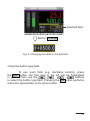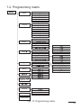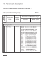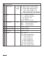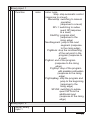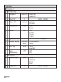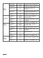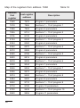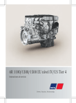
1
DUAL LOOP CONTROLLER
RE92 TYPE
USER’S MANUAL
1
2
Contents
1. INTRODUCTION ..................................................................... 5
1.1. Purpose .................................................................................................. 5
1.2. Controller properties ............................................................................... 5
2. CONTROLLER SET .................................................................. 6
3. BASIC REQUIREMENTS, OPERATIONAL SAFETY .............................. 7
4. INSTALLATION ...................................................................... 7
4.1. Controller installation.............................................................................. 7
4.2. Electrical connections ............................................................................. 9
4.3. Recommendations for installation ........................................................ 14
5. STARTING WORK .................................................................. 15
6. STARTING THE CONTROLLER ................................................... 15
6.1. Information bar ..................................................................................... 15
6.2. Button markings ................................................................................... 16
6.3. Screen with fixed set-point control ....................................................... 16
6.4. Screen with programming control ........................................................ 17
6.5. Change of displayed screens ................................................................ 17
6.6. Edit mode ............................................................................................. 18
6.7. Context menu ....................................................................................... 20
7. CONTROLLER CONFIGURATION ................................................. 21
7.1. Menu access password ......................................................................... 21
7.2. Programming matrix............................................................................. 23
7.3. Parameters description ......................................................................... 24
8. INPUTS AND OUTPUTS OF THE CONTROLLER ................................ 39
8.1. Measuring input 1 ................................................................................. 39
8.2. Measuring input 2 ................................................................................. 40
8.3. Measuring input 3 ................................................................................. 40
8.4. Binary inputs......................................................................................... 41
3
9. CONTROLLER OUTPUTS .......................................................... 42
9.1. Controlling outputs ............................................................................... 42
9.2. Alarm outputs ....................................................................................... 44
9.3. Retransmission outputs ........................................................................ 45
9.4. Signal outputs....................................................................................... 46
10. LOOP CONFIGURATION ......................................................... 47
10.1. Controlled signal ................................................................................. 47
10.2. Control types ...................................................................................... 48
10.3. Control range ...................................................................................... 54
10.4. Set value in loop ................................................................................. 54
10.5. Control algorithms .............................................................................. 54
11. PROGRAMMING CONTROL ..................................................... 59
11.1. Description of the programming control parameters .......................... 59
11.2. Defining the set value programs ......................................................... 62
12. MODBUS........................................................................... 65
12.1. Introduction ........................................................................................ 65
12.2. Error codes ......................................................................................... 66
12.3. Register map ...................................................................................... 66
13. SOFTWARE UPGRADE ......................................................... 106
14. TECHNICAL DATA .............................................................. 107
15. CONTROLLER ORDERING CODE ............................................. 112
This manual is valid for the controller using software v1.05.00.
4
1. INTRODUCTION
1.1. Purpose
Two-loop RE92 controller used to control temperature
and other physical values (e.g. pressure, humidity, flow level).
It can control two objects independently or control two physical
values in one object (e.g. two-chamber furnaces).
1.2. Controller properties
RE92 controller is characterized by the following features:
two-loop control and measurement,
•
3,5’’ TFT full-color screen, resolution: 320 x 240 pixel,
•
•
intuitive handling via six buttons and graphic user interface,
•
two universal measuring inputs (for thermoresistors, thermocouples or standard linear signals),
•
additional input,
•
communication interfaces: RS-485 Modbus Slave, Modbus
TCP Slave,
•
six binary outputs,
•
two voltage and current analog outputs,
•
three binary inputs,
•
object transducers supply output,
•
software upgrade possibility using SD card,
•
two-step control, three-step step-by-step control, three-step
control of heating-cooling type,
•
SMART PID innovative algorithm,
•
alarms.
5
2. Controller set
Complete set of the controller includes:
1.controller..............................................
2.seal......................................................
3.holders to fix the meter in the panel.....
4.plug with 16 screw terminals................
5.plug with 10 screw terminals................
6.user manual ........................................
7.guarantee card.....................................
1 pc
1 pc
4 pcs
2 pcs
2 pcs
1 pc
1 pc
l
k
m
n
3. BASIC REQUIREMENTS, OPERATIONAL
SAFETY
The controller conforms to a safety standard EN 61010-1.
Additional comments concerning safety:
Assembly and installation of the electrical connections
•
should conducted only by people authorized to perform
assembly of electric devices.
Always check the state of connections before turning
•
the controller on.
Prior to taking the controller housing off, always turn
•
the supply off and disconnect measuring circuits.
Removal of the controller housing during the warranty
•
period voids the warranty.
The device is designed to installation and usage in the indu•
strial electromagnetic environment.
A switch or a circuit-breaker should be installed in the buil•
ding or facility. This switch should be located near the device,
easily accessible by the operator, and suitably marked.
4. INSTALLATION
4.1. Controller installation
Fix the controller to the board with three screw
brackets as shown in the fig. 1A slot in the panel must have
the following dimensions: 92.5+0.6 x 92.5+0.6 mm. The thickness
of the panel material cannot exceed 6 mm.
7
Fig. 1. Controller installation.
Dimensions of the controller are presented on the fig. 2.
76,7
69
96
92
22
Fig. 2. Controller dimensions.
4.2. Electrical connections
The controller has three separate strips with screw
terminals. Two strips with 16 terminals each allow to connect
all signal sources by a wire with a 2.5 mm2 cross-section,
and two strips with 10 terminals each allow for connecting by
a wire with 1.5 mm2 cross-section.
Supply
Out6
Out5
Out4
Out3
Out2
Out1
Out
In3
In2
In1
In3B In2B In1B
Out2A
Out1A
Fig. 3. Connection strips of the controller.
9
CONNECTING THE SUPPLY
supply
supply should be connected to the terminals
51 and 52, according to technical data
CONNECTION OF 1 AND 2 INPUT
IN2
IN2
IN1
IN1
thermoresistor Pt100
in 3-wire system
thermoresistor Pt100
in 2-wire system
IN2
IN2
IN1
IN1
thermoresistor Pt1000
10
thermocouples
IN2
IN2
IN1
IN1
voltage input
0...5/10 V
current input
0/4...20 mA
CONNECTION OF INPUT 3
current input
0/4..20 mA
potentiometric
input
voltage input
0...5/10 V
CONNECTION OF THE BINARY OUTPUTS
load
OUT6 OUT5 OUT4 OUT3 OUT2 OUT1
output 1–6 – relay
11
load
OUT2 OUT1
output 1 and 2 – voltage 0/5 V
CONNECTING THE ANALOG OUTPUTS
load
load
OUT1A
output 1A – current 0/4–20 mA
and voltage 0–10 V
load
load
OUT2A
output 2A – current 0/4–20 mA
and voltage 0–10 V
12
CONNECTING THE BINARY INPUTS
IN1B
volt-free binary inputs
IN2B
IN3B
CONNECTING THE RS-485 INTERFACE
RS-485 slave interface
CONNECTING OBJECT TRANSDUCERS SUPPLY
supply object transducers of load up to 30 mA
ETHERNET CONNECTION
For Ethernet connection use the category 5 shielded
twisted-pair wire with RJ-45 connector, compliant to
the following standards:
•
EIA/TIA 568A for both connectors in strike-through connection (i.e. between RE92
and hub or switch),
•
EIA/TIA 568A for the first connector and EIA/
TIA 568B for the second one in the cross-over
connection (i.e. when connecting RE92
to the computer).
13
4.3. Recommendations for installation
To achieve full electromagnetic resistance of the controller, it is necessary to follow the rules described below:
–
do not supply the controller from the network in the proximity of devices generating high pulse noises and do not apply
common earthing circuits,
–
apply network filters,
–
wires leading measuring signal should be twisted in pairs
and for the resistance sensors in the three-wire connection
they should use twisted wires of exactly the same length,
cross-section and resistivity protected by shielding,
–
all shields should be one-side earthed or connected
to the protection wire, the nearest possible to the controller,
–
as a rule of thumb, wires transmitting different signals should be spaced as far as it is possible (at least 30 cm) and
should be crossed only at the right angle (90 degrees)°.
– to connect RE92 controller to the Ethernet it is recommended to use:
•
U/FTP – twisted pair cable with separate foil shielding
for every pair,
•
F/FTP – twisted pair cable with separate foil shielding
for every pair and additional foil shielding for the cable,
•
S/FTP (former SFTP) – twisted pair cable with separate foil shielding for every pair and additional mesh
cable shielding,
•
SF/FTP (former S-STP) – twisted pair cable
with separate foil shielding for every pair and additional
mesh and foil cable shielding.
14
5. STARTING WORK
After turning a supply on, the controller displays logo and then
moves to the normal operational mode.
6. STARTING THE CONTROLLER
6.1. Information bar
Information bar displays the state of outputs, binary
inputs and real-time clock. When active binary outputs
and inputs are displayed in black, inactive ones are displayed
in light grey color. State of the outputs, binary inputs and realtime clock can be hidden.
state of outputs
state of binary
inputs
date
time
Fig. 4. Information bar
15
6.2. Button markings
Depending on the service location, controller buttons
can perform different functions. Functions are described
in the bar on the bottom of the screen. If the button lacks
description, it is inactive at the moment. Fig. 5 shows an example
of the button marking.
Function
of button 1
Function
of button 2
Function
of button 3
Function
of button 4
Function
of button 5
Fig. 5. Buttons marking - example
6.3. Screen with fixed set-point control
Fig. 6. Screen with fixed set-point control
16
Function
of button 6
6.4. Screen with programming control
Fig. 7. Screen with programming control
6.5. Change of displayed screens
Button Screens allows for switching between two
loops - first and second. Fig. 8 presents the change of the displayed screens for the controller with fixed set-point control.
Button Screens
17
via Context
Menu
Button Screens
via Context
Menu
Fig. 8. Change of the displayed screens - example
6.6. Edit mode
Changing the value in the edit field.
To change the value in the edit field (i.e. set value),
press the Edit button, the first field of the list will by highlighted
in yellow. Then use the
,
,
,
buttons
to select the edit field for change. After pressing the Change
button, use
,
buttons to change the number position;
,
increase or decrease the value of the selected
number. The change must be accepted with the OK button or
cancelled with the Cancel button.
18
selected field
Button: Change
Fig. 9. Changing the value in the edit field.
Using the button type field.
To use such field (e.g. start/stop control), press
the Edit button; the first item in the list will be highlighted
in yellow. Then use the
,
,
,
buttons
to select the button type field. Pressing the OK button performs
a function appropriate to the given button.
19
Button OK
Fig. 10. Using the button type field.
6.7. Context menu
Pressing the ContxtM button displays the context
menu. This menu allows for quick access to a given feature.
Fig. 11. Context menu
20
7. CONTROLLER CONFIGURATION
7.1. Menu access password
To switch to the controller configuration from the screen
display level, choose the
Menu button. Use selection
and access password window will appear. On the first
run, there is only one user [Admin] with no set password.
It is possible to create four users with different access
rights. User [Admin] has all the rights, and can set them
for the other users. User privileges are selected from
the menu: Security g
User g
Level. [Level 0]
allows
for
changing
all
parameters,
including
the [Security], [Level 1] allows to change all parameters with the exception of the [Security] submenu,
[Level 2] allows for changing the set values, current program,
date and time.
Button
OK
Button
21
Button
OK
Button
Button
OK
22
MENU
7.2. Programming matrix
Analog input 1
Analog input 2
Analog input 3
Binary input 1
Binary input 2
Binary input 3
Inputs
Outputs
Output 1
Output 2
Output 3
Output 4
Output 5
Output 6
Analog output 1
Analog output 2
Inputs
Measured value
Setpoint value
Control
PID parameters
Loop
Inputs
Measured value
Setpoint value
Control
PID parameters
Loop
Programs
Config.Prg
Segment 1
Alarms
Segment 15
Security
User 1
User 2
User 3
Settings
Information
Fig. 12. Programming matrix
23
7.3. Parameters description
The list of parameters is presented in the table 1.
Symbol
of parameter
Lista parametrów konfiguracji
Table 1
Parameter modification range
Parameter
name
Factory
setting
sensors
linear input
Inputs
Analog input 1
Input type
24
Pt100
Pt100 : thermoresistor Pt100
Pt500 : thermoresistor Pt500
Pt1000: thermoresistor Pt1000
Ni100 : thermoresistor Ni100
Ni1000: thermoresistor Ni1000
Cu100 : thermoresistor Cu100
Tc J : J type thermocouple
Tc T : T type thermocouple
Tc K : K type thermocouple
Tc S : S type thermocouple
Tc R : R type thermocouple
Tc B : B type thermocouple
Tc E : E type thermocouple
Tc N : N type thermocouple
Tc L
: L type thermocouple
0..20mA: linear current 0-20mA
4..20mA: linear current 4-20mA
0..5V : linear voltage 0-5 V
0..10V : linear voltage 0-10 V
Unit
°C
°C : degrees Celsius
°F : degrees Fahrenheit
PU: physical units
%: percent
%RH: relative humidity
Dot.level
DP1
DP0 : without
a decimal
place
DP1 : 1 decimal
place
Compensation
Auto
Auto
Manual
Comp. temp.
0°C
0...50°C
DP0 : without
a decimal
place
DP1 : 1 decimal
place
DP2 : 2 decimal
places
-
MinInpAnalog
0
-
-9999...99999
MaxInpAnalog
100
-
-9999...99999
Correction
Filter
0
0.2
-35.00...35.00
Off: filter off
0.2: time constant 0.2 s
0.5: time constant 0.5 s
1: time constant 1 s
2: time constant 2 s
5: time constant 5 s
10: time constant 10 s
20: time constant 20 s
50: time constant 50 s
100: time constant 100 s
Analog input 2
as per analog
input 1
25
Analog input 3
Input type 1)
Unit
Dot.level
°C
DP1
0..20mA: linear current 0-20mA
4..20mA: linear current 4-20mA
0..5V: linear voltage 0-5 V
0..10V: linear voltage 0-10 V
R100: potentiometric input 100 Ohm
R1000: potentiometric input 1000 Ohm
°C : degrees Celsius
°F : degrees Farenheit
PU: physical units
%: percent
%RH: relative humidity
DP0 : without a decimal place
DP1 : 1 decimal place
DP2 : 2 decimal places
MinWeAnalog
0
-9999...99999
MaxWeAnalog
100
-9999...99999
0
-35.00...35.00
Korekta
Filter
26
4..20mA
0..10V
R100
0.2
Off: filter off
0.2: time constant 0.2 s
0.5: time constant 0.5 s
1: time constant 1 s
2: time constant 2 s
5: time constant 5 s
10: time constant 10 s
20: time constant 20 s
50: time constant 50 s
100: time constant 100 s
Binary input 1
Function
none
none: none
Stop: stop automatic control
(response to a level)
ManualOp: switching to manual
operation
(response to a level)
SP+1: switching to subse
quent SP(response
to a level)
StartPrg: program start
(response to the
rising edge)
NextSegment: jump to the next
segment (response
to the rising edge)
PrgBlock: stop the incrementing
of the set point in the
program (response to
a level)
PrgEnd: end of the program
(response to the rising
edge)
PrgStop: stop of the program
with possible continuation
(response to the rising
edge)
PrgStopBeg: stop the program and
jump to the beginning
(response to the
rising edge)
SP-IN3: switching to subsequent SP from the
additional input
(response to the rising
edge)
Binary input 2
as per binary
input 1
27
Binary input 3
as per binary
input 1
Outputs
Output 1
28
Connections
None
None: none
Loop 1: loop 1
Loop 2: loop 2
Input 1: input 1
Input 2: input 2
Input 3: input 3
INP1+2+3: input 1 + input 2 +
input 3
BinInp1: binary input 1
BinInp2: binary input 2
BinInp3: binary input 3
InvBinInp1: inverted binary input 1
InvBinInp2: inverted binary input 2
InvBinInp3: inverted binary input 3
Function
None
None: none
Heating: heating
Cooling: cooling
Opening: valve opening
Closing: valve closing
Alarm: alarm
Event Prg: progr. control event
CascadeSlv: signal of the slave
loop with cascade
control
Prg.Occ
None
Output type
-
Imp. period
20.0
None: none
Occ.1.Sec: event 1 from a section
Occ.2.Seg: event 2 from a section
Occ.3.Sec: event 3 from a section
Occ.4.Sec: event 4 from a section
Occ.5.Sec: event 5 from a section
Occ.6.Sec: event 6 from a section
Prg.Block.: deviation block
None:
Transmitter:
SSR:
0.5...99.0
Output 2
...
Output 6
as per output 1
Analog output 1
Connections
None
None: none
Loop 1: loop 1
Loop 2: loop 2
Input 1: input 1
Input 2: input 2
Input 3: input 3
INP1+2+3: input 1 + input 2 +
input 3
Function
None
None: none
Heating: heating
Cooling: cooling
Retransmission: retransmission
Retr. source
PV
PV: measuring value
SP: set value
Deviation: set value - measuring
value
29
Min for retr.
0
-9999...99999
Max for retr.
100
I-type output
4-20 mA
4-20mA: current 4...20 mA
0-20mA: current 0...20 mA
-9999...99999
U-type output
0-10V
0-10V: voltage 0...10 V
Analog output 2
as per analog
output 1
Loop 1
Inputs
Measuring
value
Val for Inp1
1
-10.00...10.00
Val for Inp2
1
-10.00...10.00
Val for Inp3
1
Binary inp.
30
Inp1: input 1
Inp2: input 2
Inp3: input 3
Inp1+Inp2: input 1 + input 2
Inp1+Inp3: input 1 + input 3
Inp2+Inp3: input 2 + input 3
-10.00...10.00
None: none
BinInp1: binary input 1
BinInp2: binary input 2
BinInp3: binary input 3
BinInp1,2: binary input 1 and 2
BinInp1,3: binary input 1 and 3
BinInp2,3: binary input 2 and 3
BinInp1,2,3: binary input 1, 2 and 3
Set point value
SP type
Program no.
SP1
Prg01
SP1: SP1 set point value
SP2: SP2 set point value
SP3: SP3 set point value
SP4: SP4 set point value
IN3: set point value from input 3
PRG: set point value from program
Prg01: program no 1
Prg02: program no 2
Prg03: program no 3
Prg04: program no 4
Prg05: program no 5
Prg06: program no 6
Prg07: program no 7
Prg08: program no 8
Prg09: program no 9
Prg10: program no 10
(for loop 2: Prg11–Prg20)
SP1
0
-9999...99999
SP2
0
-9999...99999
SP3
0
-9999...99999
SP4
0
-9999...99999
SPL
-199
-9999...99999
SPH
999
-9999...99999
SP accrual
Off
Ramp rate
0
Off: off
accrual/min: accrual in units /
minute
accrual/h: accrual in units / hour
-9999...99999
31
Control
Control type
Algorithm
Hysteresis
Heating
PID
Off: control off
Heating: heating-type control
Cooling: cooling-type control
Heat-Cool: heating-cooling control
Valve: step-by-step valve
control
Feedback valve.: step-by-step
feedback valve control
On-Off: on-off algorithm
PID: PID algorithm
2
0.1...100.0
Distance
0.0
-99.9...99.9
Valve Open
Time
30 s
3...600 s
Valve Close
Time
30 s
3...600 s
Min Work
Time
0.1 s
0.1...99.0 s
Out Min
0,00%
0.0...100.0 %
Out max
100.00%
0.0...100.0 %
Signal
demage
0
-100.0...100.0
Lower reg.
threshold
0
-9999...99999
Upper reg.
threshold
800
-9999...99999
30.0 °C
0.1...550.0 °C
(0.1...990.0 °F)
PID Parameters
PID 1
Pb
32
Ti
300 s
0...9999 s
Td
60.0 s
0.0...2500.0 s
Y0
0.00%
0...100.0 %
100.00%
0.1...200.0 %
PID 2
PID 3
PID 4
as per PID1
PID C
Pb
Ti
300 s
0...9999 s
Td
60.0 s
0.0...2500.0 s
Gain Scheduling
GS Type
Off
Off: off
SP: switched according to set
value
Set: fixed set
GS level no.
2
GS Level 1-2
0
-9999...99999
GS Level 2-3
0
-9999...99999
GS Level 3-4
GS Set
0
PID1
2: 2 PID sets used
3: 3 PID sets used
4: 4 PID sets used
-9999...99999
PID1: PID1 set
PID2: PID2 set
PID3: PID3 set
PID4: PID4 set
Loop 2
as per loop 1
33
Programs
Program 1
Config. Prg
PrgStart
Start PV
Start SP
Start PV
Start SP
0
Time Unit
mm:ss
Ramp Unit
Min
Min
Hour
Block
Off
Off
Lower
Upper
Intern.
Cycles Number
1
Supply decay
Continuation
End prg.
Gain
scheduling
Stop
Off
-9999...99999
mm:ss
hh:mm
1...9999
Continuation
Stop
Stop
Last SP
Off
On
Odcinek 1
Section type
Target SP
34
Time
0
Time
Accrual
Hold
End
-9999...99999
Segment time
00:00
00:00... 99:59
Ramp rate
0.1
0.1...999.9
Deviation
0
-9999...99999
Event 1
Off
Off
On
Event 2
Off
Off
On
Event 3
Off
Off
On
Event 4
Off
Off
On
Event 5
Off
Off
On
Event 6
Off
Off
On
PID set
PID1
PID1
PID2
PID3
PID4
Segment 2
...
Segment 10
as Segment 1
Program 2
...
Program 20
as Program 1
35
Alarms
Alarm 1
Type
SP
Deviation
Hysteresis
Memory
Abs.
upper
Abs. upper.: absolute upper
Abs. lower.: absolute lower
Rel. upper.: relative upper
Rel. lower.: relative lower
Rel. intern.: relative internal
Rel. extern.: relative external
100
-9999...99999
0
-9999...99999
2
Off
0.1...99.9
Off: off
On: on
Alarm 2
...
Alarm 6
as Alarm 1
Modbus
Address
36
1
1...247
Speed
9600 bps
4800 bps
9600 bps
19.2k bps
38.4k bps
57.6k bps
115.2k bps
Mode
RTU 8N2
Off
RTU 8N2
RTU 8E1
RTU 8O1
RTU 8N1
Modbus TCP 2)
On
No
Port number
Ethernet
No
Yes
502
0...65535
2)
DHCP
On
Off: off
On: on
IP Address
127.0.0.1
0.0.0.0...255.255.255.255
Subnet mask
255.0.0.1
0.0.0.0...255.255.255.255
0.0.0.0
0.0.0.0...255.255.255.255
Default
gateway
Safety
Admin
On
Yes
No
Yes
Password
0...99999999
User 1
On
Level
Password
Yes
Level 2
No
Yes
Level 0: all parameters change
Level 1: change of all parameters
.other than the Security
submenu
Level 2: change of SP, program
number, clock settings
0...99999999
User 2
same as User 1
37
User 3
same as User 1
Settings
LCD
illumination
100%
0...100 %
Language
Polish
English
Polish
Show out state
No
No
Yes
Show b.inp
state
No
No
Yes
Show clock
No
No
Yes
Hours
Date
Manufacturer’s
settings
Revert to manufacturer’s settings
(other than Ethernet group settings)
Information
Type
RE92
Loader version
eg. 1.00
Program
version
eg.
1.00.00
Serial number
eg.
12010001
MAC Address
2)
1) – default setting and extent of the changes depends on input 3 field
in the ordering code
2) – shown for Ethernet version
38
8. INPUTS AND OUTPUTS OF THE CONTROLLER
RE92 controller is fitted with two measuring inputs, one
additional input (optional) and three binary inputs.
8.1. Measuring inputs 1
Input 1 is the source of the measured value used
for control and alarms.
Input 1 is an universal input capable of accommodating
various sensors or standard signals. Input signal is selected with
a [Input type] parameter. Displayed unit is set through the [Unit]
parameter. Position of the decimal point that determines measured and set values is set through the [Digit Point] parameter.
For thermocouple, a cold terminal compensation must be
set through a [CJC Type] parameter. When the [CJC Type]
parameter is set to [Auto], compensation is automatic;
when it is set to [External], the compensation temperature is set
by the [CJC Temp] parameter.
For the linear inputs, set the indication for the lower and upper
analog input threshold through the [LowScale] and [HighScale]
parameter.
Correction of the indicated measuring value is done through
the [Shift] parameter.
When the measuring value is unstable, a digital filter
with a programmable time constant value may be used.
When using this feature, use the lowest filter time constant value
that allows for the stable measuring value. When the time constant is too high, it may cause the control to become unstable.
The range of a filter time constant – a [Filter] parameter – may
be set to 0.2 to 100 seconds.
39
Measuring input 1 parameters can be found in menu: Inputs g
Analog input 1.
8.2. Measuring input 2
Input 1 is the source of the measured value used
for control and alarms.
Measuring input 2 parameters are the same as the ones
for input 1 can be found in menu: Inputs g Analog input 2.
8.3. Measuring input 3
Input 3 may be used as:
•
signal controlled for any loop (as the independent input
or component for compound signal on different input),
•
set value for any loop,
•
additional measurement point – displayed on a measurement screen.
Input 3 is an input that can accommodate the standard signals.
Input signal is selected with a [Input type] parameter. Displayed
unit is set through the [Unit] parameter. Position of the decimal
point that determines measured and set values is set through
the [Digit Point] parameter.
Set the indication for a lower and upper analog input threshold
through the [LowScale] and [HighScale] parameter.
Correction of the indicated measuring value is done through
the [Shift] parameter.
When the measuring value is unstable, a digital filter
with a programmable time constant value may be used.
The range of a filter time constant – a [Filter] parameter – may
be set to 0.2 to 100 seconds.
40
Measuring input 3 parameters can be found in menu: Inputs g
Analog input 3.
8.4. Binary inputs
The function of the binary inputs are set through
the [Function] parameter that can be found in: menu:
Inputs g Binary input 1, Inputs g Binary input 2 and Inputs g
Binary input 3. Then you need to allocate binary inputs
to the appropriate loop.
The following functions of the binary input are available:
•
no function – state of binary input does not influence
the controller operation,
•
stop – during active binary input the control is interrupted
and control outputs start to function as after sensor failure;
alarm and retransmission operate normally,
•
switch to manual – during active binary input, the controller is in the manual operation mode,
•
switch to the next SP – during active binary input the set
point value is switched to another (eg. from SP1 to SP2)
•
program start – after activation of binary input, the process
of programming control starts,
•
jump to next segment – after activation of binary input,
follows the jump to the next segment of programming control,
•
stop counting program set value – during active binary
input, follows the stop of set value counting for programming control
•
end of the program – jump to the end of the program after
activation of the binary input,
•
stop of the program with possible continuation – control
stop and the program stop at the current position after activation of the binary input,
•
stop the program and jump to the beginning – control
stop and the program jump to start after activating
the binary input,
41
•
switching to SP from the additional input – set point is
switched to the value of the additional input during active
binary input.
Note!
If one channel is assigned to more than one binary input,
than for each of them must be set a different function.
9. CONTROLLER OUTPUTS
RE92 controller has six binary outputs and two analog
outputs: current and voltage (optional).
9.1. Controlling outputs
[Heat] function output is a reverse output. It is used during control, when the increase of the controlled signal causes the value
of output signal to drop. Such output is allocated during the loop
configuration to the heating control, heating loop in the heating
cooling control or valve opening in the step-by-step control.
[Cool] function output is a non-reverse output (direct). It is used
during control, when the increase of the controlled signal causes
the value of output signal to increase. Such output is allocated
during the loop configuration to the cooling control, cooling loop
in the heating-cooling control or valve closing in the step-by-step
control.
For the proportional control (with the exception of the analog
outputs) an impulse period is also set. Impulse period is a time
between two subsequent input engagements during proportional control. Impulse period length should be adjusted for the dynamic properties of the object and characteristics of the output
device. It is recommended to use SSR transmitter for quick processes. Relay output is used for a contactor control in the slow42
changing processes. Long impulse periods for quick-change
processes may cause unnecessary oscillation. In theory,
the shorter impulse period is, the better the control, however
for the relay output a period should be as large, as possible to
optimize lifespan of the relay.
Impulse period setting recommendations
Output
electromagnetic
transmitter
transistor output
Table 2
Impulse period is
Load
recommended >20 s,
min. 10 s
2 A/230 V a.c.
min. 5 s
1 A/230 V a.c.
1...3 s
semiconductor
transmitter (SSR)
43
9.2. Alarm outputs
Alarm configuration is done in two steps:
1. In [Output k] submenu - where k=1...6 (menu: Outputs):
select the number of loop or input allocated to the output
•
being configured – [Assignment] parameter,
set [Function] parameter to [Alarm].
•
2. In [Alarms] submenu, for every output defined as alarm
output, please set:
alarm type – [Type] parameter,
•
set value – [SP] parameter - it is the controlled or measu•
ring signal value that engages the input,
deviation from the value set in the loop [Deviation] para•
meter - it is the control deviation that engages the input,
input engagement hysteresis – [Hysteresis] parameter
•
- a zone around the set value in which output state does
not change,
alarm memory - [Latch] parameter, [Yes] - means that
•
the alarm will be locked until confirmed by operator.
SP
absolute high
[AbsHigh]
44
SP
absolute lower
[AbsLo]
Deviation (>0)
SP
Deviation (<0)
relative high
[DevHigh.]
Deviation (>0)
SP
Deviation (<0)
relative lower
[DevLo]
Deviation
SP
Deviation
relative internal
[DevInBand]
Deviation
SP
Deviation
relative external
[DevOutBand]
Fig.13. Alarm types
9.3. Retransmission outputs
Analog output may be used for retransmission
of the selected value, e.g. for registering object temperature
or copying set values in multi-zone furnaces.
Signal retransmission is possible if the controller is fitted
with analog output 1 or 2.
Set [Function] parameter to [Retransmiss]. Type of a signal
to be retransmitted is set through the [Retr Source] parameter.
Signal can be chosen from: [PV] – controlled signal, [Deviation]
– control deviation a [SP] – set point value. The next parameter,
[Output Type], sets the analog output range. Additionally,
it is necessary to set upper and lower limit of the signal to be
retransmitted [Retr Min] and [Retr Max].
Retransmission output parameters can be found in menu:
Outputs g Analog output 1 and Outputs g Analog output 2.
Picture 14 shows method of transforming the retransmitted
signal into proper analog output signal.
45
Fig. 14. Transformation of the signal to be retransmitted
The [Retr Min] parameter may be higher than [Retr Max],
but this will cause the output signal to be inverted.
9.4. Signal outputs
Any binary output can be used for „retransmission”
of the state of given binary input. To do this, while configuring
the [Assignment] parameter choose the:
•
[EvIn1] – binary input 1 short-cut will activate the output,
•
[EvIn2] – binary input 2 short-cut will activate the output,
•
[EvIn 3] – binary input 3 short-cut will activate the output,
•
[EvIn1Neg] – binary input 1 release will activate the output,
•
[EvIn2Neg] – binary input 2 release will activate the output,
•
[EvIn3Neg] – binary input 3 release will activate the output.
46
10. LOOP CONFIGURATION
10.1. Controlled signal
The signal controlled in a loop might be a measurement from the selected source (Inp1, Inp2, Inp3) or combination
of the measured values from two inputs.
Combined control signal is calculated by the controller, using
the following formula:
Controlled signal = [Coeff. for Inp k] * Inp k + [Coeff. for Inp k] * Inp k
Where k is a input number (1...3).
Example 1:
To control the difference between input 2 and input 3 signals,
enter:
[PV]= [Inp2+Inp3]; [Coeff for Inp 2] = 1,0 [Coeff. for Inp 3] = -1,0.
Example 2:
To control the mean of input 1 and input 2 signals, enter:
[PV] = [Inp1+Inp2]; [Coeff. for Inp 1] = 0.5 [Coeff. for Inp 2] = 0.5.
10.2. Control types
Heating-type control
Controller uses this type of control when the parameter [Control
Type] in menu: Loop 1 g Control or Loop 2 g Control is set
to [Heat]. It is a reverse control, when the increase of the controlled signal causes the value of output signal to drop. Output
allocated to the loop must have the [Heat] function set.
47
Cooling-type control
Controller uses this type of control when the parameter
[Control Type] in menu: Loop 1 g
Control or Loop 2 g
Control is set to [Cool]. It is a non-reverse (direct) control,
when the increase of the controlled signal causes the value
of output signal to increase. Output allocated to the loop must
have the [Cool] function set.
Control with two heating-cooling loops
Controller uses this type of control when the parameter
[Control Type] in menu: Loop 1 g Control or Loop 2 g Control
is set to [Heat-Cool]. For every control loop, set the distance
range – [Dead Band] parameter and select the parameter set
for PID and PIDC cooling.
steering
output
w
yjście ste
ru ją ce
100%
to r gloop
łó w n y
main
(g rza n ie )
(cooling)
Band]
[R[Dead
oz s unięc
ie]
to r pauxiliary
o m o cn iczy
loop
(ch ło d(heat)
ze n ie )
0%
w
a rto ść za d a n a
setpoint
oC]
te m p e ra tu[ra
[ °C ]
temperature
Fig. 15. Control with two heating-cooling loops
48
Three-step, step-by-step control
The controller offers two algorithms of the step-by-step control
for cylinder control:
•
with no feedback signal from the valve – opening and closing
of the valve is based on PID parameters and control
deviation,
•
with the feedback signal from the valve positioning device
– opening and closing of the valve is based on PID,
control deviation and valve position read from the input 3.
To select the three-step step-by-step control, the [Control Type]
parameter in menu: Loop 1 g Control or Loop 2 g Control should
be set to [Valve] or to [Valve Fdb]. For every control loop,
set the insensitivity range for the set point, in which the valve does
not change its position - the parameter [Dead Band] and select
the set of PID parameters. Auto-tuning algorithm is not available
for the step-by-step control.
Step-by-step control with no feedback additionally requires
the parameters settings: valve open time [Valve Open Time],
valve close time [Valve Close Time], minimum valve work time
[Min Work Time].
49
Fig.16. Three-step step-by-step control with no feedback
The principle of the algorithm shown in Fig. 16 is based
on conversion of changing the control signal to the relay opening /
closing time referred to the full opening / closing time.
The differences between the calculated and the actual valve
position are unavoidable because of multiple changes in the direction of valve movement due to the inertia of a drive or its wear
in the absence of a feedback. The controller uses the function
of automatic positioning of a drive during operation to eliminate
these differences. This function does not require user intervention and its function is to extend switching on time of the relay
when the control signal reaches 0% or 100%.
The relay for opening / closing will remain on for a time equal
to the time of a valve full open / close from a moment of a signal
reaching 100% / 0%.
50
The positioning of the valve will be stopped once the signal is
equal to the maximum value.
In the specific case, the positioning is performed by completely
closing the valve, it is carried out each time after:
- turning the controller supply on
- changing full open / close time.
The time of full opening of the valve can have a different value
than the time of closing.
Both parameters should be set to the same value when using
a drive with identical times.
Cascade control
Cascade control is used in the processes with a high latency
to obtain the best quality of control.
Second loop works as a slave controller which controls the output. First loop works as the master controller and sets the set
point for the slave controller.
SP
-
PID
P ID
KLoop
anał 11
PV
prze
skalo w a rescaling
nie
zakres
tona
loop
2
range
ka
nału 2
-
PID
P ID
KLoop
anał 22
w yjście
control
steoutput
ru jące
PV
Fig. 17.Cascade control
51
First loop should be set to PID control to select the cascade control. In the second loop the parameter [Control type] in menu:
Loop 2 g
Control should be set to [Cascade]. For rescaling the master loop output set the parameters [Casc.SO Lo]
and [Casc.SO Hi] in menu: Loop 2 g Set value.
„Gain Scheduling” Function
For control systems, where the object behaves decidedly
differently in various temperatures, it is recommended to use
the „Gain Scheduling” function. The controller allows to remember up to four sets of PID parameters and switch them over
automatically. Switching between PID sets runs percussiveless
and with a hysteresis to eliminate the oscillations on switching
limits.
The parameter [Typ GS] settles the way of the function
operation.
52
[Off]
The function is disabled
[SP]
a) Switching depending on the set point value.
Additionally, one must also choose the number
of PID sets – parameter [GS Level Nb],
and set their switching levels in dependence
from the number of PID sets [GS Level 1-2], [GS
Level 2-3], [GS Level 3-4].
b) For the programmed control, one can set
the PID set individually for each segment.
First, for the given program, one must set
the parameter [Gain Scheduling] in the menu:
Programs g
Program x g
Config Prg to
[On].
[Set]
Permanently setting of one PID set. The PID set
is set through the [GS Set] parameter.
S P
P ID 4
GS
G S P
o zLevel
i o m 33 -- 44
P ID 3
G S P
o zLevel
i o m 22 -- 33
GS
P ID 2
G S PGS
o zLevel
i o m 11 -- 22
P ID 1
P ID
Fig.18.”Gain Scheduling” switched over from SP
P ID 1 . . . P I D 4
P ID 1 . . . P I D 4
P ID 1 . . . P I D 4
P ID 1 . . . P I D 4
P ID 1 . . . P I D 4
PV
c za s
time
Fig. 19. „Gain Scheduling” switched over for each segment
in the programmed control.
53
10.3. Control range
Control range is defined by [Ctrl Lim Lo] and [Ctrl Lim Hi]
parameters. Control range defines limits for the PID control
and auto-tuning algorithm.
10.4. Set value in loop
A set value in loop may be one of the four values
defined as SP1, SP2, SP3, SP4, value read from the input 3
or one of the PRG programs.
Soft start
If the value is controlled in loop via SP1, SP2, SP3 or SP4,
it is possible to determine an allowable speed of controlled
changes (i.e. soft start) during object activation or while changing the set value. It allows for smooth achievement of a target
value without re-regulation. When accrual process starts,
temporary set value changes from the measured value
to the set value allocated to a loop. Selection of the Ramp rate
unit between [rate/min] and [rate/h] is set in the [Ramp Mode]
parameter, and the Ramp rate in the [Ramp Rate] parameter.
10.5. Control algorithms
on-off algorithm
When high accuracy of a temperature control is
not required, especially for the high time constant and small
delay, it is possible to use on-off control with hysteresis.
This method ensures simple and reliable control, its downside
is the oscillation, even at low hysteresis values.
54
w y jś c ie
output
hhysteresis
iste re za
za łą czoon
ne
w yłą czooff
ne
wsetpoint
a rto ść
zavalue
dana
measured
w
a rtoś ć
value
m ie rzona
Fig. 20. Heating output operation
SMART PID algorithm
When high precision of the temperature control is necessary,
it is recommended to use PID algorithm. Innovative SMART PID
algorithm ensures increased precision in the extended range
of the control object classes.
Tuning of the controller to object is achieved by manual
setting of the proportional term, derivation term or difference term
or automatically – by auto-tuning function.
Proceeding in case of a unsatisfactory PID control
PID parameters are best selected by doubling or halving
the value. The following rules should be observed during changes:
a) Oscillations
•
increase the proportional band,
•
increase integration time,
•
decrease the differentiation time,
b) Over-regulations
•
increase the proportional band,
•
increase integration time,
•
increase the differentiation time,
55
c) Instability
•
decrease the proportional band,
•
decrease the differentiation time,
d) Free jump response:
•
decrease the proportional band,
•
decrease integration time.
Trace
Przebieg
w ielkości
regulow anej
of controlled
value
Algorytm y działania
regulatora
Controller
operation
algorithms
P
PD
PI
P ID
x
Pb
Pb
td
Pb
Pb
td
Pb
Pb
ti
td
Pb
ti
td
t
x
Pb
ti
t
x
Pb td
Pb
td
Pb
ti
t
x
Pb
Pb
ti
t
Fig.21. PID parameters correction method
56
Auto-tuning
The controller has the function to select PID settings. In most
cases these settings ensure an optimal control.
To begin the auto-tuning, one must select the field ST on the
screen of a single loop with fixed set-point control and then
press a button Exec. For the correct execution of the auto-tuning
function, the setting of [Ctrl Lim Lo] and [Ctrl Lim Hi] parameters is required. The parameter [Ctrl Lim Lo] should be set
on the value corresponding to the measured value at the switched
off control. For object temperature control, one can set 0oC.
The parameter [Ctrl Lim Hi] should be set on the value corresponding to the maximum measured value when the control is
switched on the full power.
Message: SELF symbol in the control status field informs about
the activity of the auto-tuning function. The duration of auto-tuning depends on dynamic object properties and can last maximally 10 hours. During auto-tuning or directly after it, over-regulations can occur and because of this, one must set a smaller
set point if possible.
The auto-tuning is composed of following stages:
57
The auto-tuning process will be stopped without counting PID settings, if a supply decay occurs or the field ST will be
again selected and confirmed.
If the auto-tuning is not achieved with success, the error message will be displayed.
Auto-tuning and „Gain Scheduling”
In case, when „Gain Scheduling” is used, one can carry
out the auto-tuning in two ways.
The first way consists on choosing a suitable set of PID
parameters, in which calculated PID parameters will be stored
and realizing the auto-tuning
on the level of the currently chosen set point value for the fixed
set point control. One must set the parameter [GS Type]
in the menu: Loop x g Gain Scheduling to [Set], and select
the parameter [GS Set] between [PID1] and [PID4].
The second way enables an automatic realization
of the auto-tuning for all PID sets. One must set the [GS type]
to [SP], and choose a number of PID sets for setting - the parameter [GS Level Nb] Set point values for the individual PID
sets must be provided in the parameters [SP1], [SP2], [SP3],
[SP4] in the menu: Loop x g Set point value from the lowest
to the highest.
58
11. PROGRAMMING CONTROL
11.1. Description of the programming control parameters
List of configuration parameters
Table 3
[Programs] – programs defined for programming control
...
[Program 1] - program 1 submenu
[Program 20] - program 20 submenu
[Prg.Conf.] - podmenu parametrów programu
Factory
setting
Parameter modification
range
Symbol
of parameter
Parameter
description
PrgStart
Program
start
method
Start
SP
SP mode
Initial set
value
0,0 °C
MIN…MAX 1)
Time Unit
Unit of the
segment
duration
time
mm:ss
mm:ss: minutes and seconds
hh:mm: hours and minutes
Ramp Unit
Unit of the
set value
Ramp rate
Min
Min: minutes
Hour: hours
Holdback
Type
Block from
the control
deviation
Off
Off: inactive
Lower: lower
Upper: upper
Intern.: two-sided
sensors
linear input
Start SP: from the value
defined by SP0
Start PV: from the current
measured value
59
Cycles
Number
Program
iteration no.
1
1…999
Power Fail
Control
after supply
decay
Continuation
Continuation: program
continuation
Stop: control stop
End Type
Program
end control
Stop
Stop: control stop
Last SP: fixed set-point
control with set
value from last
segment
Gain
Sched.
„Gain
Scheduling”
function for
program
Off
Off: off
On: on
...
[Segment 1] – segment no. 1 parameters submenu
[Segment 15] – segment no. 15 parameters submenu
60
Symbol
of parameter
Parameter
description
Seg.Type
Segment
type
Target SP
Set value at
the end of a
segment
Factory
setting
Time
0,0 °C
Parameter modification
range
sensors
linear input
Time: time-defined segment
Accrual: accrual-defined
segment
Hold: set value hold
End: program end
MIN…MAX 1)
00.01…99.59 2)
Seg.Duration
Segment
duration
00.01
Ramp
Rate
Set value
Ramp rate
0.1
0.1...550.0 °C
/ time unit 4)
(0.1...990.0 °F
/ time unit 4))
1...5500°C 3)/
time unit 4)
(1...9900 °F 3)/
time unit 4))
Holdback
Val
Upper control deviation value;
after it is
exceeded,
set value
accrual is
stopped
0
0.0... 200.0°C
(0.0...360.0 °F)
0...2000 °C 3)
(0...3600 °F 3))
Event 1
Event 1
state
Off
Off: off
On: on
Event 2
Event 2
state
Off
Off: off
On: on
Event 3
Event 3
state
Off
Off: off
On: on
Event 4
Event 4
state
Off
Off: off
On: on
Event 5
Event 5
state
Off
Off: off
On: on
Event 6
Event 6
state
Off
Off: off
On: on
PID set
PID set for
a segment
PID1
PID1: PID1
PID2: PID2
PID3: PID3
PID4: PID4
1)
See TBD table.
Time unit is defined by the [Time unit] parameter
3)
Resolution of the parameter depends on the [Dot.pos,] parameter,
i.e. position of the decimal point.
4)
Ramp unit is defined by the [Ramp Unit] parameter
2)
61
11.2. Defining the set value programs
Up to 20 programs may be defined. One program may
include up to 15 sections.
To ensure that parameters related to the programming
control are displayed in the menu, a [SP Mode] parameter must
be set to [PRG]. Every program must have parameters set
in the program parameters submenu. For every segment, select
a segment type and proper parameters according to the segment type,as indicated in the table 4.
List of segment configuration parameters
[Seg.Type] =
[Time]
[Seg.Type] =
[Rate]
Target SP
Target SP
Segment time
Ramp rate
Holdback Val
Holdback Val
[Seg.Type] =
[Dwell]
Table 4
[Seg.Type] =
[End]
Segment time
Picture 22 and table 5 show an example of set value program.
The program assumes that the object temperature should
increase from initial temperature to 800°C with a rate of 20°C
per minute with active deviation block.
The temperature is then maintained for 120 minutes (block
disengaged), and then drops to 50°C through 100 minutes (block
disengaged); during object cooling it is necessary to engage
the fan connected to the output 2 (in Outputs g
Output2
menu: [Function] parameter set to [Prg Event] and [Prg Event]
parameter set to [SegEvent1]).
62
PV
8 0 0 °C
5 0 °C
czas
time
O U T2
ON
OFF
40 m in
120 m in
czas
100 m in
time
Fig.22. Example program
Parameter value for the example program
Parameter
Config.
Prg
Value
Table 5
Meaning
PrgStart
Start PV
Set value accrual start
from the initial (current)
temperature
Time Unit
hh:mm
The unit of time: hours
and minutes
Ramp Unit
Min
Holdback
Val
Intern.
Cycles
Number
1
Ramp rate unit: minutes
Program block active double-sided
Program iteration no.
Power Fail
Continuation
Program continuation after
supply decay
End Type
Stop
Control end after program
closes
63
Segment 1
Segment
2
Seg.Type
Accrual
Target SP
800
Target set value: 800.0 °C
Ramp rate
20
Ramp rate 20.0 °C /
minute
Holdback
Val
50
Block active when deviation
is higher than 50.0 °C
Event 1
Off
Events 1 on output 2: off
Segment
type
Segment
time
Segment
time
02.00
Event 1
Segment 3
Segment 4
64
Off
Segment
type
Segment
time
Segment type: Ramp rate
Section type: segment
duration time
Segment time 2h00 = 120
minutes
Events 1 on output 2: off
Section type: segment
duration time
Target SP
50
Target set value: 50.0 °C
Segment
time
01.40
Segment time 1h40 = 100
minutes
Holdback
Val
0
Block inactive
Event 1
On
Events 1 on output 2: on
Segment
type
End
Section type: program end
Event1
Off
Events 1 on output 2: on
12. MODBUS PROTOCOL
12.1. Introduction
RE92 controller is equipped with RS-485 serial interface
with implemented MODBUS protocol.
Summary of the RE92 controller Modbus protocol:
– device address: 1..247,
– baud rate: 4800, 9600, 19200, 38400, 57600 bit/s,
115200 bit/s
– operation modes: RTU,
– mode: 8N2, 8E1, 8O1, 8N1,
– maximum response time: 500 ms,
– data format: float (2x16 bits),
– maximum number of registers read/written in one command: 126.
In case of Modbus TCP slave, the parameters such as device
address, baud rate, operating mode, information unit, maximal
response time are not used. Additionally a port is set by default
at 502.
Registers addresses are identical for Modbus slave and Modbus
TCP slave.
RE92 controller uses following protocol functions:
Table 6
Code
Meaning
3
n-registers read
6
1 register write
16
n-registers write
17
slave device identification
65
12.2. Error codes
If the controller receives query with the transmission error or checksum error, then such query will be ignored.
When a query with correct syntax and invalid values is found,
the controller returns an error code.
Table 7 shows error codes and their meaning.
Error codes
Code
Table 7
Meaning
Cause
01
illegal function
function is not handled by the controller
02
illegal data address
register address out of range
03
illegal data value
register value out of range or register
is readout only
12.3. Register map
Register groups map
Address
range
Value type
Table 8
Description
4000 – 4099
integer
(16 bits)
7000 – 7099
float
(2x16 bits)
value set in the two subsequent
16-bit registers, readout only registers
7100 – 7499
float
(2x16 bits)
value set in the two subsequent
16-bit registers, readout and write
registers
7600 – 12000
float
(2x16 bits)
value set in the two subsequent
16-bit registers, readout and write
registers
66
value set in the 16-bit register
Table 9
Operations
Marking
Register
address
Map of the registers from address 4000
Parameter
range
4000
-W
1…11
Command register
1 – switch to manual
operation in loop 1
2 – switch to manual
operation in loop 2
3 – switch from manual
operation to automatic
control in loop 1
4 – switch from manual
operation to automatic
control in loop 2
5 – start auto-tuning in loop 1
6 – start auto-tuning in loop 2
7 – stop auto-tuning in loop 1
8 – stop auto-tuning in loop 2
9 – alarm reset
10 – revert to default settings
(with exception of
Ethernet group and
defined programs)
11 – revert defined programs
to default settings
4001
R-
100…999
Loader version number [x100]
4002
R-
10000…65000
Description
Loader version number
[x10000]
67
4003
R-
4004
R-
0…0xFFFF
Controller status – description
in table 10
4005
R-
0…0xFFFF
Alarm status – description
in table 11
4006
R-
0…0xFFFF
Error status – description
in table 12
4007
RW
-1000…1000
Controlling signal from loop 1
[x10] (for writing during manual operation)
4008
RW
-1000…1000
Controlling signal from loop 2
[x10] (for writing during manual operation)
4009
RW
0…2359
Current time – format: hour *
100 + minutes
4010
RW
0…59
4011
RW
101…1231
68
Controller manufacture code
bit 1 0 – INPUT 3:
0 0 – input 3 – none
1 0 – output 3 – current
0/4–20 mA
1 1 – output 3 – voltage
0–10 V
bit 3 2 – OUTPUT 1 and 2:
0 1 – output 1 and 2 – relay
1 0 – output 1 and 2 – 0/5 V
bit 4 – ANALOG OUTPUTS
0 0 – analog output - none
0 1 – analog output - 2
Current time – seconds
Current date – format: month
* 100 + day
4012
RW
2000…2099
Current date – year
4013
R-
1201…9999
Serial number (older part)
4014
R-
1…9999
Serial number (younger part)
Register 4004 – controller status
Table 10
bit
Description
0
Input 1 measuring value out of measurement range
1
Input 2 measuring value out of measurement range
2
Input 3 measuring value out of measurement range
3
Loop 1 measuring value out of measurement range
4
Loop 2 measuring value out of measurement range
5
Manual operation in loop 1: 1 – active, 0 – inactive
6
Manual operation in loop 2: 1 – active, 0 – inactive
7
Auto-tuning in loop 1: 1 – active, 0 – inactive
8
Auto-tuning in loop 2: 1 – active, 0 – inactive
9
Auto-tuning in loop 1 failed
10
Auto-tuning in loop 2 failed
69
11
12
13-14
15
Soft start in loop 1: 1 – active, 0 – inactive
Soft start in loop 2: 1 – active, 0 – inactive
Reserved
Controller error – check the error register
Register 4005 – alarm state
bit
Description
0
State of the alarm 1.:1 – active, 0 – inactive
1
Status of the alarm 2.:1 – active, 0 – inactive
2
Status of the alarm 3.:1 – active, 0 – inactive
3
Status of the alarm 4.:1 – active, 0 – inactive
4
Status of the alarm 5.:1 – active, 0 – inactive
5
6-15
Status of the alarm 6.:1 – active, 0 – inactive
Reserved
Register 4006 – error register
bit
Description
0
Uncalibrated input 1
1
Uncalibrated input 2
2
Uncalibrated input 3
2
Uncalibrated input 1 (current)
3
Uncalibrated input 1 (voltage)
4
Uncalibrated input 2 (current)
5
6-14
15
70
Table 11
Uncalibrated input 2 (voltage)
Reserved
Controller memory checksum error
Table 12
Map of the registers from address 7000
Register address
Operations
7000
R
Measuring value at input 1
7002
R
Measuring value at input 2
7004
R
Measuring value at input 3
7006
R
Measuring value in loop 1
7008
R
Set point value in loop 1
7010
R
Loop 1 controlling signal in loop 1
7012
R
Loop 2 controlling signal in loop 1
7014
R
Measuring value in loop 2
7016
R
Set point value in loop 2
7018
R
Loop 1 controlling signal in loop 2
7020
R
Loop 2 controlling signal in loop 2
Table 13
Description
Register
address
Operations
Map of the registers from address 7100
Parameter
range
7100
RW
0…18
Table 14
Description
Type of input no. 1:
0 – thermoresistor Pt100
1 – thermoresistor Pt500
2 – thermoresistor Pt1000
3 – thermoresistor Ni100
4 – thermoresistor Ni1000
5 – thermoresistor Cu100
6 – J type thermocouple
7 – T type thermocouple
8 – K type thermocouple
71
9 – S type thermocouple
10 – R type thermocouple
11 – B type thermocouple
12 – E type thermocouple
13 – N type thermocouple
14 – L type thermocouple
15 – current input 0-20 mA
16 – current input 4-20 mA
17 – voltage input 0-5 V
18 – voltage input 0-10 V
7102
RW
0…2
7104
RW
0…1 3) 4)
0…2 5)
7106
RW
0…1
7108
RW
0…50.0
7110
RW
-9999…99999
Indication for the lower limit for input 1
(linear input)
7112
RW
-9999…99999
Indication for the upper limit for input 1
(linear input)
7114
RW
-35.00…35.00
Measured value shift for input 1
7116
RW
0…9
72
Unit of input no 1:
0 – degrees Celsius
1 – degrees Fahrenheit
2 – physical units
Decimal point position for input 1:
0 – without a decimal place
1 – 1 decimal place
2 – 2 decimal places
Compensation of thermocouple cold
terminals for input 1:
0 – automatic
1 – manual
Cold terminals temperature with manual
compensation for input 1
Digital filter of input no 1:
0 – filter off
1 – time constant 0.2 s
2 – time constant 0.5 s
3 – time constant 1 s
4 – time constant 2 s
5 – time constant 5 s
6 – time constant 10 s
7 – time constant 20 s
8 – time constant 50 s
9 – time constant 100 s
7118
RW
0…18
Type of input no. 2:
0 – thermoresistor Pt100
1 – thermoresistor Pt500
2 – thermoresistor Pt1000
3 – thermoresistor Ni100
4 – thermoresistor Ni1000
5 – thermoresistor Cu100
6 – J type thermocouple
7 – T type thermocouple
8 – K type thermocouple
9 – S type thermocouple
10 – R type thermocouple
11 – B type thermocouple
12 – E type thermocouple
13 – N type thermocouple
14 – L type thermocouple
15 – current input 0-20 mA
16 – current input 4-20 mA
17 – voltage input 0-5 V
18 – voltage input 0-10 V
7120
RW
0…2
Unit of input no 2:
0 – degrees Celsius
1 – degrees Fahrenheit
2 – physical units
7122
RW
0…1 3) 4)
0…2 5)
7124
RW
0…1
7126
RW
0…50.0
7128
RW
-9999…99999
Indication for the lower limit for input 2
(linear input)
7130
RW
-9999…99999
Indication for the upper limit for input 2
(linear input)
7132
RW
-35.00…35.00
Measured value shift for input 2
Decimal point position for input 2:
0 – without a decimal place
1 – 1 decimal place
2 – 2 decimal places
Compensation of thermocouple cold
terminals for input 2:
0 – automatic
1 – manual
Cold terminals temperature with manual
compensation for input 2
73
7134
RW
0…9
Digital filter of input no 2:
0 – filter off
1 – time constant 0.2 s
2 – time constant 0.5 s
3 – time constant 1 s
4 – time constant 2 s
5 – time constant 5 s
6 – time constant 10 s
7 – time constant 20 s
8 – time constant 50 s
9 – time constant 100 s
7136
RW
0…6
Type of input no. 3:
0 – none
1 – current input 0-20 mA
2 – current input 4-20 mA
3 – voltage input 0-5 V
4 – voltage input 0-10 V
5 – potentiometric input 100 Ohm
6 – potentiometric input 1000 Ohm
7138
RW
0…2
Unit of input no 3:
0 – degrees Celsius
1 – degrees Fahrenheit
2 – physical units
7140
RW
0…1 3) 4)
0…2 5)
7142
RW
-9999…99999
Indication for the lower limit for input 3
(linear input)
7144
RW
-9999…99999
Indication for the upper limit for input 3
(linear input)
7146
RW
-35.00…35.00
Measured value shift for input 3
7148
RW
0…9
74
Decimal point position for input 3:
0 – without a decimal place
1 – 1 decimal place
2 – 2 decimal places
Digital filter of input no 3:
0 – filter off
1 – time constant 0.2 s
2 – time constant 0.5 s
3 – time constant 1 s
4 – time constant 2 s
5 – time constant 5 s
6 – time constant 10 s
7 – time constant 20 s
8 – time constant 50 s
9 – time constant 100 s
7150
RW
0…10
Function of binary input 1:
0 – none
1 – stop automatic control
2 – switch to manual operation
3 – switches to subsequent SP
4 – program start
5 – jump to the next segment
6 – stops the incrementing of the set
value in program
7 – end of the program
8 – stop of the program with possible
continuation
9 – stop the program and jump to the
beginning
10 – switching to subsequent SP from
the additional input
7152
RW
0…10
Function of binary input 2:
0 – none
1 – stop automatic control
2 – switch to manual operation
3 – switches to subsequent SP
4 – program start
5 – jump to the next segment
6 – stops the incrementing of the set
value in program
7 – end of the program
8 – stop of the program with possible
continuation
9 – stop the program and jump to the
beginning
10 – switching to subsequent SP from
the additional input
7154
RW
0…10
Function of binary input 3:
0 – none
1 – stop automatic control
2 – switch to manual operation
3 – switches to subsequent SP
4 – program start
75
5 – jump to the next segment
6 – stops the incrementing of the set
value in program
7 – end of the program
8 – stop of the program with possible
continuation
9 – stop the program and jump to the
beginning
10 – switching to subsequent SP from
the additional input
7156
RW
0…12
Allocation of output 1:
0 – none
1 – loop 1
2 – loop 2
3 – input 1
4 – input 2
5 – input 3
6 – input 1 + input 2 + input 3
7 – binary input 1
8 – binary input 2
9 – binary input 3
10 – inverted binary input 1
11 – inverted binary input 2
12 – inverted binary input 3
7158
RW
0…7
Output 1 function:
0 – none
1 – heating
2 – cooling
3 – opening a valve
4 – closing a valve
5 – alarm
6 – programming control event
7160
RW
0…7
Output 1 program event:
0 – none
1 – event 1 from a segment
2 – event 2 from a segment
3 – event 3 from a segment
4 – event 4 from a segment
5 – event 5 from a segment
6 – event 6 from a segment
7 – deviation block
7162
RW
0.5…99.9
76
Output 1 imp. period
7164
RW
0…12
Allocation of output 2:
0 – none
1 – loop 1
2 – loop 2
3 – input 1
4 – input 2
5 – input 3
6 – input 1 + input 2 + input 3
7 – binary input 1
8 – binary input 2
9 – binary input 3
10 – inverted binary input 1
11 – inverted binary input 2
12 – inverted binary input 3
7166
RW
0…7
Output 2 function:
0 – none
1 – heating
2 – cooling
3 – opening a valve
4 – closing a valve
5 – alarm
6 – programming control event
0…7
Output 2 program event:
0 – none
1 – event 1 from a segment
2 – event 2 from a segment
3 – event 3 from a segment
4 – event 4 from a segment
5 – event 5 from a segment
6 – event 6 from a segment
7 – deviation block
7168
7170
RW
0.5…99.9
Output 2 imp. period
7172
RW
0…12
Allocation of input 3:
0 – none
1 – loop 1
2 – loop 2
3 – input 1
4 – input 2
5 – input 3
77
6 – input 1 + input 2 + input 3
7 – binary input 1
8 – binary input 2
9 – binary input 3
10 – inverted binary input 1
11 – inverted binary input 2
12 – inverted binary input 3
7174
RW
7176
0…7
Output 3 function:
0 – none
1 – heating
2 – cooling
3 – opening a valve
4 – closing a valve
5 – alarm
6 – programming control event
0…7
Output 3 program event:
0 – none
1 – event 1 from a segment
2 – event 2 from a segment
3 – event 3 from a segment
4 – event 4 from a segment
5 – event 5 from a segment
6 – event 6 from a segment
7 – deviation block
7178
RW
0.5…99.9
7180
RW
0…12
78
Output 3 imp. period
Allocation of input 4:
0 – none
1 – loop 1
2 – loop 2
3 – input 1
4 – input 2
5 – input 3
6 – input 1 + input 2 + input 3
7 – binary input 1
8 – binary input 2
9 – binary input 3
10 – inverted binary input 1
11 – inverted binary input 2
12 – inverted binary input 3
7182
RW
7184
0…7
Output 4 function:
0 – none
1 – heating
2 – cooling
3 – opening a valve
4 – closing a valve
5 – alarm
6 – programming control event
7 – cascade control slave loop signal
0…7
Output 4 program event:
0 – none
1 – event 1 from a segment
2 – event 2 from a segment
3 – event 3 from a segment
4 – event 4 from a segment
5 – event 5 from a segment
6 – event 6 from a segment
7 – deviation block
7186
RW
0.5…99.9
7188
RW
0…12
Allocation of input 5:
0 – none
1 – loop 1
2 – loop 2
3 – input 1
4 – input 2
5 – input 3
6 – input 1 + input 2 + input 3
7 – binary input 1
8 – binary input 2
9 – binary input 3
10 – inverted binary input 1
11 – inverted binary input 2
12 – inverted binary input 3
7190
RW
0…7
Output 5 function:
0 – none
1 – heating
2 – cooling
3 – opening a valve
4 – closing a valve
5 – alarm
Output 4 imp. period
79
6 – programming control event
7 – cascade control slave loop signal
7192
0…7
Output 5 program event:
0 – none
1 – event 1 from a segment
2 – event 2 from a segment
3 – event 3 from a segment
4 – event 4 from a segment
5 – event 5 from a segment
6 – event 6 from a segment
7 – deviation block
7194
RW
0.5…99.9
7196
RW
0…12
Allocation of input 6:
0 – none
1 – loop 1
2 – loop 2
3 – input 1
4 – input 2
5 – input 3
6 – input 1 + input 2 + input 3
7 – binary input 1
8 – binary input 2
9 – binary input 3
10 – inverted binary input 1
11 – inverted binary input 2
12 – inverted binary input 3
0…7
Output 6 function:
0 – none
1 – heating
2 – cooling
3 – opening a valve
4 – closing a valve
5 – alarm
6 – programming control event
7 – cascade control slave loop signal
0…7
Output 6 program event:
0 – none
1 – event 1 from a segment
2 – event 2 from a segment
7198
7200
80
RW
Output 5 imp. period
3 – event 3 from a segment
4 – event 4 from a segment
5 – event 5 from a segment
6 – event 6 from a segment
7 – deviation block
7202
RW
0.5…99.9
7204
RW
0…6
Allocation of analog output 1:
0 – none
1 – loop 1
2 – loop 2
3 – input 1
4 – input 2
5 – input 3
6 – input 1 + input 2 + input 3
7206
RW
0…3
Linear output 1 function:
0 – none
1 – heating
2 – cooling
3 – retransmission
7208
RW
0…2
Analog output 1 retransmission source:
0 – measuring value
1 – set value
2 – set value – measuring value
Output 6 imp. period
7210
RW
-9999…99999
Min for retr. of analog output 1
7212
RW
-9999…99999
Max for retr. of analog output 1
7214
RW
0…2
I-output type for analog output 1:
0 – none
1 – 4…20 mA
2 – 0…20 mA
7216
RW
0…2
U-output type for analog output 1:
0 – none
1 – 0…5 V
2 – 0…10 V
7218
RW
0…6
Allocation of analog output 2:
0 – none
1 – loop 1
2 – loop 2
3 – input 1
81
4 – input 2
5 – input 3
6 – input 1 + input 2 + input 3
7220
RW
0…3
Linear output 2 function:
0 – none
1 – heating
2 – cooling
3 – retransmission
7222
RW
0…2
Analog output 2 retransmission source:
0 – measuring value
1 – set point value
2 – set point value – measuring value
7224
RW
-9999…99999
Min for retr. of analog output 2
7226
RW
-9999…99999
Max for retr. of analog output 2
7228
RW
0…2
I-output type for analog output 2:
0 – none
1 – 4…20 mA
2 – 0…20 mA
7230
RW
0…2
U-output type for analog output 2:
0 – none
1 – 0…5 V
2 – 0…10 V
7232
RW
0…5
Measuring value in loop 1:
0 – input 1
1 – input 2
2 – input 3
3 – input 1 + input 2
4 – input 1 + input 3
5 – input 2 + input 3
7234
RW
-10.0…10.0
Input 1 coefficient in loop 1
7236
RW
-10.0…10.0
Input 2 coefficient in loop 1
7238
RW
-10.0…10.0
Input 3 coefficient in loop 1
7240
RW
0…7
82
Binary inputs in loop 1:
0 – none
1 – binary input 1
2 – binary input 2
3 – binary input 3
4 – binary input 1 and 2
5 – binary input 1 and 3
6 – binary input 2 and 3
7 – binary input 1, 2 and 3
7242
RW
0…5
SP type in loop 1:
0 – SP1 set point value
1 – SP2 set point value
2 – SP3 set point value
3 – SP4 set point value
4 – set point value from input 3
5 – set point value from program
7244
RW
0…9
Program number on loop 1:
0 – program number 1
1 – program number 2
2 – program number 3
3 – program number 4
4 – program number 5
5 – program number 6
6 – program number 7
7 – program number 8
8 – program number 9
9 – program number 10
7246
RW
-9999...99999
SP1 set value in loop 1
7248
RW
-9999...99999
SP2 set value in loop 1
7250
RW
-9999...99999
SP3 set value in loop 1
7252
RW
-9999...99999
SP4 set value in loop 1
7254
RW
-9999...99999
SP setting lower limit in loop 1
7256
RW
-9999...99999
SP setting upper limit in loop 1
7258
RW
0…2
7260
RW
-9999...99999
Set value accrual in loop 1:
0 – off
1 – accrual in units / minute
2 – accrual in units / hour
Set value Ramp rate in loop 1
83
7262
RW
0…5
Control type in loop 1:
0 – control off
1 – heating-type control
2 – cooling-type control
3 – heating-cooling control
4 – step-by-step valve control
5 – step-by-step feedback valve control
7264
RW
0…1
Control algorithm in loop 1:
0 – on-off algorithm
1 – PID algorithm
7266
RW
0,1...100,0
Hysteresis in loop 1
7268
RW
-99.9...99.9
Distance range in loop 1
7270
RW
-100.0...100.0
Control signal in loop 1
7272
RW
-9999...99999
Control lower limit in loop 1
7274
RW
-9999...99999
Control upper limit in loop 1
7276
RW
0...550.0 [oC]
0...990.0 [oF]
PID1 set proportional band in loop 1
7278
RW
0...9999
7280
RW
0.0...2500.0
Differentiation time constant [s] from
PID1 set in the loop 1
7282
RW
0.0...100.0
Control signal correction for P or PD
of PID1 set in loop 1
7284
RW
0...550.0 [oC]
0...990.0 [oF]
PID2 set proportional band in loop 1
7286
RW
0...9999
7288
RW
0.0...2500.0
Differentiation time constant [s] from
PID2 set in the loop 1
7290
RW
0.0...100.0
Control signal correction for P or PD
of PID2 set in loop 1
7292
RW
0...550.0 [oC]
0...990.0 [oF]
PID3 set proportional band in loop 1
84
Integration time constant [s] from PID1
set in the loop 1
Integration time constant [s] from PID2
set in the loop 1
7294
RW
0...9999
7296
RW
0.0...2500.0
Differentiation time constant [s] from
PID3 set in the loop 1
7298
RW
0.0...100.0
Control signal correction for P or PD
of PID3 set in loop 1
7300
RW
0...550.0 [oC]
0...990.0 [oF]
PID4 set proportional band in loop 1
7302
RW
0...9999
7304
RW
0.0...2500.0
Differentiation time constant [s] from
PID4 set in the loop 1
7306
RW
0.0...100.0
Control signal correction for P or PD
of PID4 set in loop 1
7308
RW
7310
RW
0...9999
Integration time constant [s] of cooling
loop in the loop 1
7312
RW
0.0...2500.0
Differentiation time constant [s] of cooling loop in the loop 1
7314
RW
0...2
„Gain Scheduling” function in loop 1:
0 – off
1 – switched according to set value
2 – selected fixed PID set
7316
RW
0...2
Number of PID sets for Gain Scheduling, switched according to the value set
in loop 1:
0 – 2 PID sets used
1 – 3 PID sets used
2 – 4 PID sets used
7318
RW
-9999...99999
Switching level for PID1 and PID2 set,
switched as per value set in loop 1
7320
RW
-9999...99999
Switching level for PID2 and PID3 set,
switched as per value set in loop 1
Integration time constant [s] from PID3
set in the loop 1
Integration time constant [s] from PID4
set in the loop 1
0.1...200.0 [%] Proportional band of cooling loop
in loop 1
85
7322
RW
-9999...99999
7324
RW
0...3
Fixed PID set for Gain Scheduling in
loop 1:
0 – PID1 set
1 – PID2 set
2 – PID3 set
3 – PID4 set
7326
RW
0…5
Measuring value in loop 2:
0 – input 1
1 – input 2
2 – input 3
3 – input 1 + input 2
4 – input 1 + input 3
5 – input 2 + input 3
Switching level for PID3 and PID4 set,
switched as per value set in loop 1
7328
RW
-10.0…10.0
Input 1 coefficient in loop 2
7330
RW
-10.0…10.0
Input 2 coefficient in loop 2
7332
RW
-10.0…10.0
Input 3 coefficient in loop 2
7334
RW
0…7
Binary inputs in loop 2:
0 – none
1 – binary input 1
2 – binary input 2
3 – binary input 3
4 – binary input 1 and 2
5 – binary input 1 and 3
6 – binary input 2 and 3
7 – binary input 1, 2 and 3
7336
RW
0…5
SP type in loop 2:
0 – SP1 set point value
1 – SP2 set point value
2 – SP3 set point value
3 – SP4 set point value
4 – set point value from input 3
5 – set point value from program
86
7338
RW
10…19
7340
RW
-9999...99999
SP1 set value in loop 2
7342
RW
-9999...99999
SP2 set value in loop 2
7344
RW
-9999...99999
SP3 set value in loop 2
7346
RW
-9999...99999
SP4 set value in loop 2
7348
RW
-9999...99999
SP setting lower limit in loop 2
7350
RW
-9999...99999
SP setting upper limit in loop 2
7352
RW
0…2
7354
RW
-9999...99999
7356
RW
0…5
Control type in loop 2:
0 – control off
1 – heating-type control
2 – cooling-type control
3 – heating-cooling control
4 – step-by-step valve control
5 – step-by-step feedback valve control
7358
RW
0…1
Control algorithm in loop 2:
0 – on-off algorithm
1 – PID algorithm
7360
RW
0.1...100.0
Hysteresis in loop 2
7362
RW
-99.9...99.9
Distance range in loop 2
Program number on loop 2:
10 – program number 11
11 – program number 12
12 – program number 13
13 – program number 14
14 – program number 15
15 – program number 16
16 – program number 17
17 – program number 18
18 – program number 19
19 – program number 20
Set value accrual in loop 2:
0 – off
1 – accrual in units / minute
2 – accrual in units / hour
Set value Ramp rate in loop 2
87
7364
RW
-100.0...100.0
Control signal in loop 2
7366
RW
-9999...99999
Control lower limit in loop 2
7368
RW
-9999...99999
Control upper limit in loop 2
o
7370
RW
0...550.0 [ C]
0...990.0 [oF]
7372
RW
0...9999
7374
RW
0.0...2500.0
Differentiation time constant [s] from
PID1 set in the loop 2
7376
RW
0.0...100.0
Control signal correction for P or PD
of PID1 set in loop 2
7378
RW
0...550.0 [oC]
0...990.0 [oF]
PID2 set proportional band in loop 2
7380
RW
0...9999
7382
RW
0.0...2500.0
Differentiation time constant [s] from
PID2 set in the loop 2
7384
RW
0.0...100.0
Control signal correction for P or PD
of PID2 set in loop 2
7386
RW
0...550.0 [oC]
0...990.0 [oF]
PID3 set proportional band in loop 2
7388
RW
0...9999
7390
RW
0.0...2500.0
Differentiation time constant [s] from
PID3 set in the loop 2
7392
RW
0.0...100.0
Control signal correction for P or PD
of PID3 set in loop 2
7394
RW
0...550.0 [oC]
0...990.0 [oF]
PID4 set proportional band in loop 2
7396
RW
0...9999
88
PID1 set proportional band in loop 2
Integration time constant [s] from PID1
set in the loop 2
Integration time constant [s] from PID2
set in the loop 2
Integration time constant [s] from PID3
set in the loop 2
Integration time constant [s] from PID4
set in the loop 2
7398
RW
0.0...2500.0
Differentiation time constant [s] from
PID4 set in the loop 2
7400
RW
0.0...100.0
Control signal correction for P or PD
of PID4 set in loop 2
7402
RW
7404
RW
0...9999
Integration time constant [s] of cooling
loop in the loop 2
7406
RW
0.0...2500.0
Differentiation time constant [s] of cooling loop in the loop 2
7408
RW
0...2
Gain Scheduling function in loop 2:
0 – off
1 – switched according to set value
2 – selected fixed PID set
7410
RW
0...2
Number of PID sets for Gain Scheduling, switched according to the value set
in loop 2:
0 – 2 PID sets used
1 – 3 PID sets used
2 – 4 PID sets used
7412
RW
-9999...99999
Switching level for PID1 and PID2 set,
switched as per value set in loop 2
7414
RW
-9999...99999
Switching level for PID2 and PID3 set,
switched as per value set in loop 2
7416
RW
-9999...99999
Switching level for PID3 and PID4 set,
switched as per value set in loop 2
7418
RW
0...3
Fixed PID set for Gain Scheduling
in loop 2:
0 – PID1 set
1 – PID2 set
2 – PID3 set
3 – PID4 set
7420
RW
0...5
Alarm type 1:
0 – absolute upper
1 – absolute lower
2 – relative upper
3 – relative lower
4 – relative internal
5 – relative internal
0.1...200.0 [%] Proportional band of cooling loop
in loop 2
89
7422
RW
-9999...99999
Alarm 1 set value
7424
RW
-9999...99999
Alarm 1 deviation (for relative alarms)
7426
RW
0.1...99.9
7428
RW
0...1
Memory of the alarm 1:
0 – off
1 – on
7430
RW
0...5
Alarm type 2:
0 – absolute upper
1 – absolute lower
2 – relative upper
3 – relative lower
4 – relative internal
5 – relative internal
7432
RW
-9999...99999
Alarm 2 set point value
7434
RW
-9999...99999
Alarm 2 deviation (for relative alarms)
Alarm 1 hysteresis
7436
RW
0.1...99.9
7438
RW
0...1
Memory of the alarm 2:
0 – off
1 – on
7440
RW
0...5
Alarm type 3:
0 – absolute upper
1 – absolute lower
2 – relative upper
3 – relative lower
4 – relative internal
5 – relative internal
7442
RW
-9999...99999
Alarm 3 set point value
7444
RW
-9999...99999
Alarm 3 deviation (for relative alarms)
7446
RW
0.1...99.9
7448
RW
0...1
90
Alarm 2 hysteresis
Alarm 3 hysteresis
Memory of the alarm 3:
0 – off
1 – on
7450
RW
0...5
7452
RW
-9999...99999
Alarm 4 set point value
7454
RW
-9999...99999
Alarm 4 deviation (for relative alarms)
Alarm type 4:
0 – absolute upper
1 – absolute lower
2 – relative upper
3 – relative lower
4 – relative internal
5 – relative internal
7456
RW
0.1...99.9
7458
RW
0...1
Memory of the alarm 4:
0 – off
1 – on
7460
RW
0...5
Alarm type 5:
0 – absolute upper
1 – absolute lower
2 – relative upper
3 – relative lower
4 – relative internal
5 – relative internal
7462
RW
-9999...99999
Alarm 5 set point value
7464
RW
-9999...99999
Alarm 5 deviation (for relative alarms)
7466
RW
0.1...99.9
7468
RW
0...1
Memory of the alarm 5:
0 – off
1 – on
7470
RW
0...5
Alarm type 6:
0 – absolute upper
1 – absolute lower
2 – relative upper
3 – relative lower
4 – relative internal
5 – relative internal
7472
RW
-9999...99999
Alarm 4 hysteresis
Alarm 5 hysteresis
Alarm 6 set point value
91
7474
RW
-9999...99999
Alarm 6 deviation (for relative alarms)
7476
RW
0.1...99.9
7478
RW
0...1
7480
RW
1...247
7482
RW
0...5
Baud rate
0 – 4800 bps
1 – 9600 bps
2 – 19.2k bps
3 – 38.4k bps
4 – 57.6k bps
5 – 115.2k bps
7484
RW
0...4
Transmission protocol:
0 – none
1 – RTU 8N2
2 – RTU 8E1
3 – RTU 8O1
4 – RTU 8N1
7486
RW
0...10
LCD illumination
7488
RW
0...1
Language
0 – English
1 – Polish
7490
RW
0...1
Shot outputs state
0 – no
1 – yes
7492
RW
0...1
Show binary inputs state
0 – no
1 – yes
7494
RW
0...1
Show clock
0 – no
1 – yes
7496
RW
0.0...100.0 [%] Minimum control signal in loop 1
7498
RW
0.0...100.0 [%] Maximum control signal in loop 1
92
Alarm 6 hysteresis
Memory of the alarm 6:
0 – off
1 – on
Address
7500
RW
0.0...100.0 [%] Minimum control signal in loop 2
7502
RW
0.0...100.0 [%] Maximum control signal in loop 2
Table 15
Parameter
range
7600
RW
0…9
Number of realized program
(0 means first program) – loop 1
7602
RW
0…1
Program start/stop – loop 1
0 – program stop
1 – program start (saving causes
program to start from the beginning)
7604
RW
0…1
Program set value accrual stop
– loop 1
0 – off
1 – on
7606
RW
0…14
Realized segment (0 means first
segment) – loop 1
Saving causes a jump to the given
segment
Register
address
Marking
Operations
Map of the registers from address 7600
Description
93
7608
R-
Control status – loop 1
0 – control stop (in the first
section)
1 – control stop (in the current
section)
2 – program running
3 – control deviation block active
4 – set value accrual stop
(via button, binary input or
interface)
5 – program end
7610
R-
Number of cycles left - loop 1
7612
R-
Section time elapsed [s] - loop 1
7614
R-
Segment time remaining [s] – loop 1
7616
R-
Program time elapsed [s] - loop 1
7618
R-
Program time remaining [s] – loop 1
7620
RW
Reserved
7622
RW
Reserved
7624
RW
Reserved
7626
RW
Reserved
7628
RW
7630
RW
10…19
7632
RW
0…1
Program start/stop – loop 2
0 – program stop
1 – program start (saving causes
program to start from
the beginning)
7634
RW
0…1
Program set value accrual stop
– loop 2
0 – off
1 – on
94
Reserved
Number of realized program
(10 means eleventh program) – loop 2
7636
RW
0…14
Realized segment (0 means first
segment) – loop 2
Saving causes a jump to the given
segment
7638
R-
Control status – loop 2
0 – control stop (in the first
section)
1 – control stop (in the current
section)
2 – program running
3 – control deviation block active
4 – set value accrual stop
(via button, binary input
or interface)
5 – program end
7640
R-
Number of cycles left - loop 2
7642
R-
Section time elapsed [s] - loop 2
7644
R-
Segment time remaining [s] – loop 2
7646
R-
Program time elapsed [s] - loop 2
7648
R-
Program time remaining [s] – loop 2
7650
RW
Reserved
7652
RW
Reserved
7654
RW
Reserved
7656
RW
Reserved
7658
RW
Reserved
95
Map of the registers from address 7660
96
Table 16
Address
first
register
Last register
address
7660
7676
Program 1 parameters
7678
7886
Sections 1 – 15 of program 1
7888
7904
Program 2 parameters
7906
8114
Sections 1 – 15 of program 2
Description
8116
8132
Program 3 parameters
8134
8342
Sections 1 – 15 of program 3
8344
8360
Program 4 parameters
8362
8570
Sections 1 – 15 of program 4
8572
8588
Program 5 parameters
8590
8798
Sections 1 – 15 of program 5
8800
8816
Program 6 parameters
8818
9028
Sections 1 – 15 of program 6
9028
9044
Program 7 parameters
9046
9254
Sections 1 – 15 of program 7
9256
9272
Program 8 parameters
9274
9482
Sections 1 – 15 of program 8
9484
9500
Program 9 parameters
9502
9710
Sections 1 – 15 of program 9
9712
9728
Program 10 parameters
9730
9938
Sections 1 – 15 of program 10
9940
9956
Program 11 parameters
9958
10166
Sections 1 – 15 of program 11
10168
10184
Program 12 parameters
10186
10394
Sections 1 – 15 of program 12
10396
10412
Program 13 parameters
10414
10622
Sections 1 – 15 of program 13
10624
10640
Program 14 parameters
10642
10850
Sections 1 – 15 of program 14
10852
10868
Program 15 parameters
10870
11078
Sections 1 – 15 of program 15
11080
11096
Program 16 parameters
11098
11306
Sections 1 – 15 of program 16
11308
11324
Program 17 parameters
11326
11534
Sections 1 – 15 of program 17
11536
11552
Program 18 parameters
11554
11762
Sections 1 – 15 of program 18
11764
11780
Program 19 parameters
11782
11990
Sections 1 – 15 of program 19
11992
11008
Program 20 parameters
12010
11218
Sections 1 – 15 of program 20
97
Parameter
range
+0
PrgStart
RW
0…1
+2
Start SP
RW
MIN..MAX
1)
+4
Time Unit
RW
0…1
Unit of the segment
duration time
0 – minutes and
seconds
1 – hours and minutes
Ramp
Unit
RW
0…1
Unit of the set value
Ramp rate
0 – minutes
1 – hours
+8
Holdback
Type
RW
0…3
Control deviation block
0 – inactive
1 – lower
2 – upper
3 – double-sided
+ 10
Cycles
Number
RW
1…999
+6
98
Program parameters
Marking
Operations
Table 17
Register address
Register map for single program
Description
Program start method
0 – from the value
defined by SP0
1 – from the current
measured value
Initial set point value
Program iteration no.
Power
Fail
RW
0…1
Control after supply
decay
0 – program continuation
1 – control stop
+ 14
End Type
RW
0…1
Program end control
0 – control stop
1 – fixed set-point control with set value from
last segment
+ 16
Gain
Sched.
RW
0…1
„Gain Scheduling”
function for program
0 – off
1 – on
+0
Seg.Type
RW
0…3
Segment type
0 – time-defined
segment
1 – accrual-defined
segment
2 – set value hold
3 – program end
Target SP
RW
MIN..MAX
1)
Set value at the end
of a segment
Seg.
Duration
RW
1…5999
Segment duration time
+6
Ramp
Rate
RW
1…5500
1)
Set value Ramp rate
+8
Holdback
Val
RW
0…2000
1)
Upper control deviation
value; when it is
exceeded, set value
accrual is stopped
+2
+4
Segment 1
+ 12
99
+ 10
Events
RW
0…7
Events state (bit sum)
bit 0 set – event 1
bit 1 set – event 2
bit 2 set – event 3
bit 3 set – event 4
bit 4 set – event 5
bit 5 set – event 6
+ 12
PID
RW
0…3
PID set for a segment
0 – PID1
1 – PID2
2 – PID3
3 – PID4
Seg.Type
Target SP
+ 18
Segment
time
+ 20
+ 22
Segment 2
+ 14
+ 16
Ramp
rate
Holdback
Val
+ 24
Events
+ 26
PID
+ 28
Seg.Type
Target SP
+ 32
Segment
time
+ 36
Segment 3
+ 30
+ 34
Ramp
rate
Holdback
Val
+ 38
Events
+ 40
PID
100
as per segment 1
as per segment 1
+ 42
Seg.Type
Target SP
+ 46
Segment
time
+ 48
+ 50
Segment 4
+ 44
Ramp
rate
Holdback
Val
Events
+ 54
PID
+ 56
Seg.Type
+ 58
Target SP
+ 60
Segment
time
Segment 5
+ 52
+ 62
as per segment 1
Ramp
rate
+ 64
Holdback
Val
+ 66
Events
+ 68
PID
as per segment 1
101
Seg.Type
+ 72
Target SP
+ 74
Segment
time
+ 76
Segment 6
+ 70
+ 78
Ramp
rate
Holdback
Val
+ 80
Events
+ 82
PID
Seg.Type
Target SP
+ 88
Segment
time
+ 92
Segment 7
+ 84
+ 86
+ 90
Ramp
rate
Holdback
Val
+ 94
Events
+ 96
PID
102
as per segment 1
as per segment 1
+ 98
Seg.Type
Target SP
+ 102
Segment
time
+ 104
+ 106
Segment 8
+ 100
Ramp
rate
Holdback
Val
+ 108
Events
+ 110
PID
Seg.Type
Target SP
+ 116
Segment
time
+ 120
Segment 9
+ 112
+ 114
+ 118
Ramp
rate
Events
+ 124
PID
Seg.Type
Target SP
+ 130
Segment
time
Segment 10
+ 126
+ 128
+ 134
as per segment 1
Holdback
Val
+ 122
+ 132
as per segment 1
Ramp
rate
as per segment 1
Holdback
Val
+ 136
Events
+ 138
PID
103
Seg.Type
+ 142
Target SP
+ 144
Segment
time
+ 146
+ 148
Segment 11
+ 140
Ramp
rate
Holdback
Val
Events
+ 152
PID
+ 154
Seg.Type
+ 156
Target SP
+ 160
Segment 12
+ 150
+ 158
+ 162
Segment
time
Ramp
rate
Events
+ 166
PID
Seg.Type
Target SP
+ 172
Segment
time
Segment 13
+168
+ 170
+ 176
Ramp
rate
Holdback
Val
+ 178
Events
+ 180
PID
104
as per segment 1
Holdback
Val
+ 164
+ 174
as per segment 1
as per segment 1
+ 182
Seg.Type
Target SP
+ 186
Segment
time
+ 188
+ 190
Segment 14
+ 184
Ramp
rate
Holdback
Val
+ 192
Events
+ 194
PID
Seg.Type
Target SP
+ 200
Segment
time
+ 204
Segment 15
+ 196
+ 198
+ 202
as per segment 1
Ramp
rate
as per segment 1
Holdback
Val
+ 206
Events
+ 208
PID
13. SOFTWARE UPGRADE
Controller software may be upgraded. New software
versions are available as a one file on the following website:
http://www.lumel.com.pl.
After copying this file to the main directory of the SD card,
controller software may begin To do this: when controller is off,
press and hold left button and then turn a controller supply on.
105
14. TECHNICAL DATA
Input 1 and 2
Input signals and measuring ranges
Sensor type
Pt100
Pt500
Table 18
Standard
EN
60751+
A2:2009
Intrinsic
error
Range
-200...850 °C
-328...1562 °F
0.20%
-200...850 °C
-328...1562 °F
0.20%
-200...850 °C
-328...1562 °F
0.20%
Ni100
-60...180 °C
-76...356 °F
0.20%
Cu100
-50...180 °C
-58...356 °F
0.20%
Pt1000
Fe-CuNi (J)
-100...1200 °C
-148...2192 °F
0.30%
Cu-CuNi (T)
-100...400 °C
-148...752 °F
0.30%
NiCr-NiAl (K)
-100...1372 °C
-148...25016 °F
0.30%
PtRh10-Pt (S)
0...1767 °C
32...32126 °F
0.50%
0...1767 °C
32...3212.6 °F
0.50%
PtRh13-Pt (R)
EN 605841:1997
PtRh30-PtRh6 (B)
0...1767 °C
1)
32...3212.6 °F
1)
0.50%
NiCr-CuNi (E)
-100...1000 °C
-148...1832 °F
0.30%
NiCrSi-NiSi (N)
-100...1300 °C
-148...2372 °F
0.30%
chromel – kopel (L)
-100...800 °C
-148...1472 °F
0.30%
0...20 mA
0...20 mA
0.2% ±
1 digit
4...20 mA
4...20 mA
0.2% ±
1 digit
linear voltage (U)
0...5 V
0...5 V
0.2% ±
1 digit
linear voltage (U)
0...10 V
0...10 V
0.2% ±
1 digit
linear current (I)
linear current (I)
1)
GOST R
8.585-2001
Intrinsic error is related to the measuring range 200…1767 °C
(392...3212,6 °F)
106
Additional errors:
– from automatic compensation
reference junction temperature
£ 2°C
– from automatic resistance compensation
of resistance thermometer wires
£ 0.3°C
Current flowing through
resistance thermometer sensor
0.22 mA
Measurement time
0.25 s
Input resistance:
– for voltage input
– for current input
100 kW
10 W
Error detection in the measurement circuit:
- thermocouple, Pt100, Pt1000
measuring range
exceeded
- 0¼10 V
over 11 V
- 0¼5 V
over 5.5 V
- 0¼20 mA
over 22 mA
- 4¼20 mA
over 1 mA and over 22 mA
Input 3 (depends on input 3 in ordering code)
Sensor type
Range
Intrinsic error
linear current
0...20 mA
0.2% ± 1 digit
linear current
4...20 mA
0.2% ± 1 digit
linear voltage
0...5 V
0.2% ± 1 digit
linear voltage
0...10 V
0.2% ± 1 digit
potentiometric 100 W
0...100 W
0.2% ± 1 digit
potentiometric 1000 W
0...1000 W
0.2% ± 1 digit
107
Measurement time
0.25 s
Input resistance:
– for voltage input
– for current input
100 kW
50 W
Setting range of controller parameters:
see Table 1
Binary inputs 1…3
– shorting resistance
– opening out resistance
Output 1 and 2 types:
– relay voltageless
–
voltage transistor
Output 3…6 types:
– relay voltageless
voltageless
£ 10 kW
³ 100 kW
NOC contact,
load capacity 2 A/230 VAC
0/5 V, max load capacity
40 mA
NOC contact,
load capacity 2 A/230 VAC
Analog output types 1A and 2A:
– analog voltage
0…10 V atRload ³ 1 kW
–
analog current
0…20 mA, 4…20 mA
at Rload £ 500 W
Way of output operation:
– reverse
– direct
for heating
for cooling
Analog outputs error
0.5% of the range
Digital interface
– protocol
RS-485
Modbus
108
–
baud rate
–
–
–
mode
address
maximal response time
4800, 9600, 19200, 38400,
57600, 115200 bit/s
RTU – 8N2, 8E1, 8O1, 8N1
1…247
500 ms
Digital interface
protocol
–
Ethernet
Modbus TCP slave
Supply of object transducers
24V d.c. ±5 %,
max.: 30 mA
Rated operating conditions:
supply voltage
–
supply voltage frequency
–
ambient temperature
–
storage temperature
–
relative air humidity
–
preheating time
–
operating position
–
resistance of wires connecting
–
the resistance thermometer or
thermocouple with controller
85…253 V a.c./d.c.
40…440 Hz
0…23…50 °C
-20…+70 °C
< 85 % (no condensation)
30 min
any
< 20 W / wire
Power input
< 16 VA
Weight
< 0.5 kg
Protection grade ensured by the housing
acc. to EN 60529
from the frontal plate
IP65
–
from the terminal side
IP20
–
109
Additional errors in rated operating conditions caused by:
£ 100 % intrinsic error
– ambient temperature change
value /10 K.
Safety requirements acc. to EN 61010-1
III,
– installation category
2,
– pollution level
– maximum phase-to-earth operating voltage:
– for supply circuit, output 300 V
50 V
– for input circuits
< 2000 m
– altitude a.s.l.
Electromagnetic compatibility:
– noise immunity, acc. to standard EN 61000-6-2
– noise emission, acc. to standard EN 61000-6-4
110
18. CONTROLLER ORDERING CODE
Versions and ordering
Table 19
RE92 - X X X X X XX X X
Input 3:
none
0
current: 0/4...20 mA
1
voltage: 0...5/10 V
2
potentiometric transmitter: 100/ 1000 Ω 3
Output 1 and 2:
2 relays
1
2 binary outputs 0/5 V
2
Analog outputs:
none
0
2 analog outputs 0/4...20 mA and 0...10 V
1
Ethernet:
none
with Ethernet
Transducer supply:
none
24 V d.c.
Version:
standard
1)
custom-made
Language version:
Polish
English
2)
other
Additional quality requirements:
without additional quality requirements
with extra quality inspection certificate
2)
acc. to customer’s request
0
1
0
1
00
XX
P
E
X
0
1
X
1) - the code will be established by the manufacturer
2) - only after agreeing with a manufacturer
111
IN STANDARD:
–
2 universal inputs
–
3 binary inputs
–
6 relay outputs
–
RS-485 Modbus Slave
–
supply 85...253 V a.c./d.c
Example of order:
The code RE92 -1-1-0-1-0-00-E-0 means:
RE92 - RE92 controller,
1 - with additional input: current 0/4...20 mA,
1 - output 1 and 2: 2 relays,
0 - analog outputs: none,
1 - with Ethernet,
0 - transducer supply: none,
00 - standard version,
E - user's manual in English,
0 - without additional quality requirements.
112
113
114
115
RE92-09C
LUMEL S.A.
ul. Słubicka 1, 65-127 Zielona Góra, Poland
Tel.: (48-68) 45 75 100
Fax: (48-68) 45 75 508
e-mail:[email protected]
http://www.lumel.com.pl
Export Department:
Tel.: (48-68) 45 75 302
Fax: (48-68) 32 54 091
e-mail: [email protected]
116