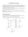
1
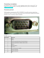
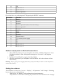
PowerWatcher user manual
PowerWatcher device is intended for data measurement, indication and storage of the major
operational parameters of an electric vehicle, electric scooter or other electric transportation means.
The device is capable of measuring a current, voltage, speed, defined point temperature, and of
indicating a number of parameters calculated as functions thereof, e.g. a power, energy consumption
rate, number of charge/discharge cycles, mileage, etc.
Data is indicated via an external device which can be an Android (v3.0 or newer) based smartphone
or a tablet capable of supporting the OTG function.
Power supply range of the PowerWatcher is 50…250V DC (practically down to 30V DC in the
most cases).
Measured current range depends on the shunt resistance. Full scale range (for ADC purpose) of the
shunt voltage is from -120mV to +120mV.
Connecting the sensors
Use any suitable shunt for the current measurement, taking into account your range of current as
suggested above. Set shunt resistance in microOhms in the settings menu.
Temperature measurement is calibrated for NTCM-100K thermoresistor type.
Use a hercon from bike-computer or a Hall sensor with an open-collector output as a speed sensor.
Connecting a smartphone
PowerWatcher works as “USB Device”, hence smartphone must be able to support OTG. The
simplest test to check this ability is connecting USB-flash memory stick to a smartphone and
making sure that it works.
Connectors pin-out
VGA interface connector a.k.a. DE-15/ DSUB15 is used for sensors connection.
Alternatively some or all of the connecting wires can be directly soldered into PCB to
minimize errors caused by contact resistance.
DSUB15 pin-out.
Pin number
Function
1
Shunt -
2
Shunt +
3
Common potential (minus of traction battery)
4
Common potential (for thermo sensor return)
5
Battery +
6
Thermo sensor +
7
Not used
8
+5V (sensors power supply)
9
Common potential
10
Common potential
11
RX
12
TX
13
Speed sensor 1
14
Speed sensor 2
15
Common potential
Pin-out for direct wire soldering into PCB bypassing the DSUB15 connector:
Pin number
Function
1
Battery +
2
Not used
3
Not used
4
Common potential (minus of traction battery)
5
Common potential
6
Not used
7
Shunt +
8
Shunt -
9
Not used
10
Thermo sensor +
11
+5V (sensors power supply)
12
RX
13
TX
14
Speed sensor 1
15
Speed sensor 2
Software deployment on Android based device
1. Check USB Host function of your smartphone. Download “USB Host Diagnostics” from
Play Market and run it. Run the diagnostics and agree to “fix errors” as the program
propmts.
2. Download “PowerWatcher” program from Play Market.
3. After the connection of your smartphone to PowerWatcher device the software will run
automatically.
Warning: Device gives power supply from battery (not from USB!). So device works only then it
connected to battery.
Setting the software
“PowerWatcher” software has 3 screens – “Display”, “All parameters” and “Settings”. Switching
between the screens is by double tap.
- “Main screen” or “Display” solely indicates the selected parameters.
- “All parameters” screen allows selecting the parameter set to be indicated on the “Display”
-
screen.
“Settings” screen allows changing general settings. There are several initial settings to be
done prior to use: “Wheel length” for correct speed and distance calculation; “Shunt
resistance” for correct current derived parameters calculation; “Battery capacity”; “Charged
voltage” i.e. voltage of the traction battery when it is fully charged. To adjust current
consumption indication if it differs from zero in idling condition of a vehicle, press the
button “Reset current offset to zero”.
Working algorithm
For correct calculations of energy related data the PowerWatcher device must be connected to the
traction battery at all times, i.e. while charging and discharging.
The criterion of the end-of-charging during the charging process is defined as:
-
the battery voltage having exceeded the pre-set value of “Charged voltage”;
-
and 1% of “Battery capacity” extra charge added into the battery after that event.
When the end-of-charging criterion is satisfied, then a number of other parameters gets reset, e.g.
daily mileage, consumed energy, average and peak speed, current, etc. Battery charge level is then
set at 100%.
The remaining battery charge percentage is calculated based on the full battery capacity and spent
charge in amp-hours.