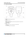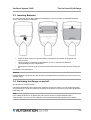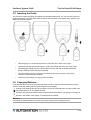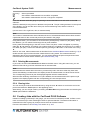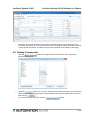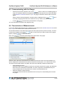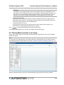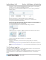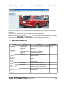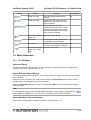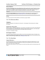
1
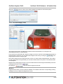
User Manual
Version of this User Manual:
2.0
Version of the PC software:
2.1.0.1
Version of the gauge firmware:
12c
http://www.carchecksystem.com
CarCheck System PLUS
Table of content
1 Preamble........................................................................................................................................... 3
1.1 About this User Manual.............................................................................................................. 3
1.2 Intended Use............................................................................................................................. 3
1.3 Legal Notice............................................................................................................................... 3
1.4 Type Plate.................................................................................................................................. 4
1.5 Version Numbers....................................................................................................................... 4
1.6 Other Sources of Information..................................................................................................... 4
2 The CarCheck System PLUS............................................................................................................ 4
2.1 Scope of Supply......................................................................................................................... 4
2.2 Starting Up................................................................................................................................. 6
3 The CarCheck PLUS Gauge.............................................................................................................. 7
3.1 General Information................................................................................................................... 7
3.2 Controls and Display.................................................................................................................. 8
3.3 Inserting Batteries...................................................................................................................... 9
3.4 Switching the Gauge on and off................................................................................................. 9
3.5 Inserting the Probe.................................................................................................................. 10
3.6 Changing Batteries.................................................................................................................. 10
4 Operating the Gauge....................................................................................................................... 11
4.1 Display..................................................................................................................................... 11
4.2 Menu Navigation...................................................................................................................... 11
4.3 Basic Settings.......................................................................................................................... 14
5 Measurements................................................................................................................................. 17
5.1 General Information................................................................................................................. 17
5.2 Placing the Probe.................................................................................................................... 17
5.3 Zero Point Reference............................................................................................................... 19
5.4 Individual Measurements......................................................................................................... 19
5.5 Working with Jobs.................................................................................................................... 20
5.6 Creating Jobs with the CarCheck PLUS Software...................................................................21
5.7 Deleting Jobs / Batches / Measurements................................................................................22
6 CarCheck System PLUS Software at a Glance...............................................................................22
6.1 Creating Jobs........................................................................................................................... 22
6.2 Adding Components................................................................................................................ 23
6.3 Communicating with the Gauge............................................................................................... 24
6.4 Transmission of Measurements...............................................................................................24
6.5 Placing Measurements on an Image.......................................................................................25
6.6 Creating Report Files............................................................................................................... 27
7 CarCheck PLUS Software – A Detailed View...................................................................................28
7.1 The Program Window.............................................................................................................. 28
7.2 The different Program Views................................................................................................... 28
7.3 Button Reference List.............................................................................................................. 34
7.4 Menu Reference...................................................................................................................... 35
8 Data Backup.................................................................................................................................... 38
8.1 Back up Data........................................................................................................................... 38
8.2 Reload Data............................................................................................................................. 38
9 Software Information........................................................................................................................ 39
10 Installation options......................................................................................................................... 40
10.1 Updates................................................................................................................................. 40
10.2 Repairs.................................................................................................................................. 40
10.3 De-installation........................................................................................................................ 40
11 Appendix........................................................................................................................................ 42
11.1 Errors – causes and solutions................................................................................................42
11.2 Manufacturer / service address.............................................................................................. 43
11.3 Technical data........................................................................................................................ 44
2/44
CarCheck System PLUS
Preamble
1 Preamble
1.1 About this User Manual
This user manual is intended for anyone operating the CarCheck system. All local regulations
regarding the handling of electrical devices must still be observed. We assume a basic knowledge of
the procedures, possibilities, and limits of coating thickness measurement. For the installation and
operation of the CarCheck PLUS software, a general knowledge of computers and the Windows
operating system is necessary.
1.2 Intended Use
The CarCheck PLUS gauge provides non-destructive coating thickness measurement of non-magnetic
coatings such as lacquer, paint, chrome, or zinc on steel or iron, as well as of electrically insolating
coatings such as lacquer, paint or aluminum oxide (anodizing) on non-iron metals.
The CarCheck PLUS software provides means to exchange documentation and measurements with
the CarCheck PLUS gauge. It does not support other devices.
The device has not been approved for any other use.
If you have questions regarding the handling of the device or the software not answered in this
manual, please contact the point of sale or write to:
Automation Dr. Nix GmbH & Co. KG
Robert-Perthel-Straße 2
D-50739 Cologne, Germany
www.carchecksystem.com
1.3 Legal Notice
Disclaimer
We guarantee that, to the best of our knowledge, this product is free of defects and works as
advertized and stated in this user manual. We do not guarantee or promise any other product
attributes or the fitness of the product for any other than its intended use. We do not accept liability if
the product is used for purposes that are not covered by the chapter Intended use of this user
manual.
Trademarks and Registered Trademarks that are used in this document are property of their
respective owners and are used without special notice.
Copyright
© Copyright Automation Dr. Nix GmbH & Co. KG Cologne, Germany. All rights reserved.
This document may not be reproduced in whole or in part without explicit permission of Automation Dr.
Nix GmbH & Co. KG. User manuals are for personal use only.
EU Directives
The coating thickness gauge meets all requirements as specified in the European directive
89/336(regarding electromagnetic compatibility).
3/44
CarCheck System PLUS
Preamble
1.4 Type Plate
For the purpose of exact information, the name and serial number of the model can be found on a type
label in the battery compartment of the gauge casing. The type label of the probe is attached to its
connecting side. It is covered while the probe is inserted.
Please take a note of this information to have it at hand in case of questions or when ordering spare
parts.
1.5 Version Numbers
You can find the version number of the firmware installed on your CarCheck PLUS gauge by
accessing the System Info submenu found under Setup → System Info.
The version numbers of the installed CarCheck PLUS software and additional system components can
be found under About → About.
Please take a note of this information to have it at hand in case of questions.
1.6 Other Sources of Information
For information and tips regarding the use of the Windows operating system and Windows
applications, refer to your Windows manual and the Windows online help.
2 The CarCheck System PLUS
2.1 Scope of Supply
•
CarCheck gauge
•
CarCheck probe Dual Fe/NFe 5mm/5mm
•
Product CD with CarCheck PLUS software, device driver, user manual as PDF file
•
Probe cable
•
2 zero reference plates (Fe and Al)
•
2 AA size batteries 1,5 V
•
USB adapter for wireless data transfer between gauge and computer
•
Printed short reference
•
Inspection certificate of the measuring probe
•
Soft pouch with belt clip
• Case for transport and storage
Check the supply for completeness and damage. Inform Automation Dr. Nix GmbH & Co. KG if you
find something damaged. We will check it for you.
Functional Characteristics
•
CarCheck System PLUS is a system for measuring the thickness of coatings on metallic
surfaces. Its main application is the measurement of lacquer thickness on steel and aluminum.
It can, nevertheless, also be used to measure e. g. chromium on a steel substrate. The
menus in the gauge and the PC software for data archiving and report generation are
especially designed for the inspection of vehicles.
•
CarCheck System PLUS includes the CarCheck PLUS gauge with coating thickness probe
and the CarCheck PLUS software.
4/44
CarCheck System PLUS
The CarCheck System PLUS
•
The device uses the magnetic measuring method and the eddy current method. Thus the
simultaneous measurements of non-magnetic coatings such as lacquer, chromium, or zinc on
steel or iron as well as measurements on electrically isolated coatings such as lacquer or
anodizing on non-iron based metal are possible.
•
The probe identifies the base material underneath the coating and switches to the
corresponding measurement method automatically.
•
In addition to individual measurements as usually used, you can choose to use a semiautomated measuring program.
•
A “Job” is created for each vehicle that is to be inspected. The CarCheck System PLUS gauge
can hold up to 10 jobs. The vehicle components (e. g. hood, right door...) can be combined in
any order to build an inspection procedure. Thus every inspector can plan his way around the
vehicle according to his personal preference.
•
CarCheck System PLUS comes with preinstalled vehicle components for common car body
designs. The user can define new components using the PC software. In the automobile
business, this could be a antiroll bar, a painted rim, or a roof railing. Thanks to the freely
selectable component names, other applications are also within reach. For the inspection of
bicycles, for example, the frame, the rims and the handle bar could be defined as
components.
•
The configuration of new components is especially easy when using the PC software. But if
the need arises to define new components on-site, for example, the bumpers of a vintage car
or the running board of a SUV, these definitions can also be created at the gauge without the
help of a computer.
•
Such parts of the vehicle that are not in their original condition any more, because they were
repainted or filled, will show increased coating thickness measurements. When such a region
has been detected, it may be of interest to determine its extent.
To achieve this, the number of measurements usually has to be increased. With the CarCheck
System PLUS, the user can take as many readings per job or per component as necessary for
the task. Of course, components can also be completely omitted from the inspection. The user
could, for example, create a standard inspection procedure that covers all possible car body
designs. If inspecting a convertible or a 2 door sports car, he can simply skip the components
that are not applicable with the push of a button.
•
CarCheck System PLUS can create inspection reports in Portable Document Format (*.pdf),
as Microsoft Word or Microsoft Excel files (*.doc, *.xls). In the report, all relevant information is
collected on the first page: information concerning the vehicle, its owner and the inspector, a
picture of the vehicle with the measurements in place and a table containing the individual
measurements for each component including the respective average thicknesses. Additional
photos of the vehicle are optionally positioned on the following pages.The created files can
easily be integrated into other documents and processed in any way. The user can integrate a
logo into the report giving a personal touch to the documents created.
•
It is not possible to place all measurements that where taken on all sides of a vehicle on one
photo. Therefore, CarCheck System PLUS includes drawings of typical car body designs that
show the vehicle from all sides. The user can easily add more drawings or photos. In addition,
CarCheck System PLUS provides a tool that enables the user to compile several photos into
one picture, so that the measurements can be placed on photos of the inspected vehicle.
•
Transmitting the data to a computer allows it to be analyzed and completely documented. Use
the provided USB adapter to establish a wireless communication between gauge and
computer.
5/44
CarCheck System PLUS
The CarCheck System PLUS
Special Features
•
Fully automated menu-driven measuring system, including individual measurements
•
Detailed documentation with analysis and documentation software
•
Any existing record can be used as a template, when several vehicles have to be inspected
with similar conditions. For every vehicle, only the changed data has to be dealt with.
•
Even when creating a completely new record, existing entries in the database can be used in
an intuitive way. If, for example, an inspector often works for a specific customer, he does not
have to enter the customers data every time. Instead, CarCheck System PLUS suggests
matching database entries, including all contact data, as soon as the first letter is entered.
•
Measurements can automatically be placed in a previously defined pattern on the image used
for the record. Thus there is no need to treat measurements individually for inspections that
have been created with a predefined procedure. Of course, measurements can be moved on
the image afterward, or be placed by hand in the first place.
•
The measuring range is up to 5000µm for Fe (steel) as well as NFe (aluminum) substrates,
•
Compact gauge, programmable at the PC in preparation of the measuring task
•
No time consuming calibration
•
Rugged measuring system
•
Easy-to-use
• 3-year warranty - Made in Germany
At the time of this writing, CarCheck System PLUS offers about 10 different user interface languages,
including English, Russian, Chinese and Korean. Support for other languages is in preparation.
2.2 Starting Up
The CarCheck PLUS gauge is ready to work as soon as the batteries are inserted.
Installation, deinstallation and update of the CarCheck System PLUS software are described in a
separate document. You find it on the CarCheck System PLUS CD where you also found this user
manual.
6/44
CarCheck System PLUS
The CarCheck PLUS Gauge
3 The CarCheck PLUS Gauge
3.1 General Information
3.1.1 Batteries and Rechargeable Batteries
Use only approved AlMn AA size batteries (1.5V) or AA size rechargeable batteries (1.2V).
Never try to charge standard batteries (1.5V).
Batteries may contain flammable material. If handled improperly, they may leak, heat, ignite, or
explode. Avoid heat and never throw batteries into a fire.
Batteries may contain toxic and corrosive material. Never disassemble or deform batteries.
Observe the polarity as indicated on the batteries (+ and –) and ensure that the batteries are inserted
into the battery compartment correctly.
Never use rechargeable and non-rechargeable batteries at the same time. Never use new batteries
together with used ones. Remove empty batteries from the compartment immediately. To avoid
leakage, remove the batteries when the device is not used over a longer period.
3.1.2 Area of Application
Use the CarCheck gauge only in dry environment. The casing is not waterproof. Penetrating water
may damage the device. The ambient temperature during operation must be between 0 and +50°C
(32°F and 122°F). Do not store the device in temperatures exceeding 60°C (140°F). Higher
temperatures may damage the display.
3.1.3 Operation
Only use the gauge for the kind of work specified in this manual and only in the manner described. All
additional actions may cause personal injury or damage property and device.
3.1.4 Maintenance
Never open the casings of gauge or probe. The device contains no parts you can repair or replace.
Maintenance and repair work may only be performed by the manufacturer Automation Dr. Nix GmbH
or by authorized personnel.
7/44
CarCheck System PLUS
The CarCheck PLUS Gauge
3.2 Controls and Display
1
2
3
4
5
6
7
Display
shows measurements and operation menus
Buttons
for operating the device
LED
flashes red during active wireless connection and data transmission and green after a
successful measurement
Measuring probe
Battery compartment
Latch
for releasing the locking of the inserted probe or the probe cable
Recessed grips
for a safe positioning of the measuring probe
8/44
CarCheck System PLUS
The CarCheck PLUS Gauge
3.3 Inserting Batteries
You can power the device with 2 AlMn AA size batteries (1.5V) or 2 AA size rechargeable batteries
(1.2V). Only use leak proof batteries.
•
Press the latch of the lid to open the battery compartment at the back of the gauge and
remove the lid.
•
Observe polarity as indicated on the batteries (+ and –) and insert the batteries
correspondingly into the compartment.
Reinsert the lid with its upper end first and take care that the latch snaps in when closing the
lid.
The gauge is now operational.
•
Caution!
Leaking batteries can destroy the device! Remove the batteries from the device it you do not use it for
a longer period.
3.4 Switching the Gauge on and off
The device has no power switch.
It activates automatically when placing the measuring probe on a surface. You can switch the gauge
on by pressing one of its four buttons. If the gauge or the probe is not used for more than 30 seconds,
it will switch off.
Note:
If you switch the device on by placing the probe onto a surface, it will automatically take a
measurement. If you use one of the buttons, the last measurement taken appears in the display.
9/44
CarCheck System PLUS
The CarCheck PLUS Gauge
3.5 Inserting the Probe
The CarCheck measuring gauge is supplied with the appropriate probe. You can connect probe and
gauge alternatively using the probe cable provided. This increases your mobility when measuring on
difficult-to-observe locations.
•
Take the gauge in one hand and press the probe latch at the back of the gauge.
•
Hold the probe with the recessed grips (7) and pull it straight down and out of the gauge.
•
Hold the bigger gauge plug of the probe cable correctly (with the nib facing towards the
gauge’s back) and insert the plug completely.
•
Hold the smaller probe plug with the nib of the plug fitting into the dent in the probe’s
connector. Insert the plug completely.
•
Fasten the probe plug by turning the latch clockwise.
3.6 Changing Batteries
If the batteries are running low, the gauge will switch off. Menu settings and measurements remain
saved. A three step battery-warning symbol appears in the display:
Changing the batteries will soon be necessary. Numerous measurements can still be taken until
the gauge switches off. The display is still lit.
Symbol to the right of the measurement: measurements still possible. The display is no longer lit.
Symbol in the middle of the display: no measurements possible.
Attention!
If changing the batteries takes more than two minutes, date and time settings are lost.
10/44
CarCheck System PLUS
Operating the Gauge
4 Operating the Gauge
4.1 Display
The display shows the measurements in large numbers next to the unit selected (µm/mm or mil). The
display also shows the menu structure and instructions when working on jobs.
4.1.1 Special Symbols
A few special signs and symbols provide additional information on the measurement and the state of
the gauge:
Measurement on ferromagnetic base material (iron or steel)
Measurement on non-magnetic base material (e. g. aluminum)
measurement recalled from the gauges memory (during measuring tasks with jobs)
Measuring error, improper base material, incorrect zero reference
Measuring mode, automated identification of base material
Active wireless connection
Acoustic signal deactivated
4.2 Menu Navigation
Most of the settings and operation features of the gauge are accessible via the menu structure
appearing on the display. Using the four buttons, you can navigate through the menu, select
parameters and activate functions.
The buttons usually have the following functions:
►
Switch to next menu level, activate feature, navigate to next Batch
◄
Back, cancel, navigate to previous Batch
▼
Open Main Menu
▲▼
Menu item, select parameter or option (dark background)
Placing the probe or pressing its tip briefly will close the menu. The last measurement will then
reappear in the display.
Note:
The gauge of the CarCheck System PLUS measuring system can operate in 2 different modes. The
memory mode is activated when a job is started. With no active job, the gauge is in standard mode.
The menus slightly differ in the 2 modes.
11/44
CarCheck System PLUS
Operating the Gauge
4.2.1 Menu Structure in Standard Mode
Main Menu
Job
◄►
new Job
▼▲
◄►
(edit name)
Job 001...
Measuring Mode ◄►
Fe
NFe
▼▲
Memory
FE/NFe
◄►
Delete All
◄►
▼▲
▼▲
Delete Values
OK
Cancel
◄►
▼▲
OK
Cancel
Info
Setup
◄►
Display
◄►
Unit
◄►
▼▲
Backlight
▼▲
mil
◄►
▼▲
Orientation
µm
Auto
Off
◄►
Normal
Flipped
Wireless
◄►
On
Off
▼▲
Energy Save
System Info
▼▲
Buzzer
◄►
▼▲
Date/Time
Off
◄►
▼▲
Language
On
◄►
Set Time
◄►
time
Set Date
◄►
date
English
Français
Deutsch
12/44
CarCheck System PLUS
Operating the Gauge
4.2.2 Menu Structure in Memory Mode
Delete Last
OK
▼▲
Job
Cancel
◄► Finish
▼▲
Measuring Mode
Info
◄► Fe
NFe
▼▲
Memory
FE/NFe
◄► [new block]
B 0001
▼▲
◄►
(edit name)
◄► Select
Show Values
B 0002
Rename
...
◄►
(edit name)
Info
Setup
◄►
Display
◄►
Unit
◄►
▼▲
Backlight
▼▲
mil
◄►
▼▲
Orientation
µm
Auto
Off
◄►
Normal
Flipped
Wireless
◄►
On
Off
▼▲
Energy Save
System Info
▼▲
Buzzer
◄►
▼▲
Date/Time
Off
◄►
▼▲
Language
On
◄►
Set Time
◄►
time
Set Date
◄►
date
English
Français
Deutsch
13/44
CarCheck System PLUS
Operating the Gauge
4.3 Basic Settings
4.3.1 Measuring Mode
You can set the measuring mode depending on the base material as a fix setting or you can have the
probe determine the measuring mode automatically.
If you know the base material and it is not changed, select Fe (ferromagnetic base material, e. g. steel
or iron) or NFe (non-ferromagnetic base material, e. g. aluminum or zinc).
If you have to switch between ferromagnetic and non-ferromagnetic base material frequently, activate
the automatic FE/NFe mode. The device uses the measuring mode last selected when switched on. If
you place the probe on different base material, the message “no NFe – Repeat!” (or “no Fe –
Repeat!”) appears in the display. Place the probe on the same spot again and the probe switches
modes automatically. You can continue with your measurements.
▼ Main Menu ▼ Measuring Mode
To open the Main menu, press the ▼ button while the gauge is switched on. Then switch to the
Measuring Mode submenu.
Select the desired measuring mode using the ▼ or ▲ buttons.
Press the ► button to activate the selected option. A dot (•) indicates the activated option.
Note:
You can access the Measuring Mode submenu using one of two ways: either follow the procedure as
described above via the main menu or directly by pressing the ◄ button. However, in memory mode,
the ◄ and ► buttons are used to navigate between batches. Thus you can reach the Measuring
Mode submenu only via the main menu.
4.3.2 Units
You can select the unit in which measurements are displayed: µm or mil. The initial setting is µm.
▼ Main Menu ▼ Setup ► Display ▼ Unit
Press the ▼ button while the gauge is switched on to access the Main menu. Then access the Unit
submenu.
Select the required unit using the ▼ or ▲ buttons.
To activate the selected option, press ►. A dot (•) indicates the option activated.
4.3.3 Date and Time
The internal calendar and watch of the CarCheck PLUS gauge save date and time with each
measurement. Take care that date and time are correct, especially concerning the documentation of
your measurements. You should check the settings each time you are about to start a measurement
task.
Setting date and time may be required:
•
•
•
if changing the batteries took longer than 2 minutes,
after switching to daylight saving time,
when measuring in another time zone.
▼ Main Menu ▼ Setup ► Date/ Time
14/44
CarCheck System PLUS
Operating the Gauge
Press the ▼ button while the gauge is switched on to enter the Main menu. Then access the
Date/Time submenu.
Select the Set Time option using the ▼ or ▲ buttons and press ►. The Set Hours option appears.
Use the ▼ or ▲ buttons to set the hour.
Press ► once to select Ok, press ► again to save the hour setting. The Set Minutes option appears.
Follow the instructions as described for setting the hour.
If you wish to cancel, press the ◄ to select Cancel and press ◄ again for confirmation.
Select the Set Time option in the Date/Time submenu using the ▼ or ▲ button and press ►. The
Set Day option appears.
Set the day, month, and year as when setting the time as described above.
4.3.4 Acoustic Signal
The gauge confirms various actions, for example entries via the buttons or measurements, with an
acoustic signal. You can switch off this signal if desired. If the signal is switched off, the
symbol
appears in the bottom left of the display.
▼ Main Menu ▼ Setup ► Buzzer
Press the ▼ button while the gauge is switched on to access the Main menu. Then access the
Buzzer. submenu.
Select the desired option using the ▼ or ▲ buttons.
Press ► to activate the option selected. A dot (•) indicates the activated option.
4.3.5 Orientation
You can adjust the orientation of the display to facilitate the handling of the gauge. If, for example, you
connected probe and gauge using the adapter cable and the gauge is lying on a table you can read
the display better if it is rotated by 180°.
▼ Main Menu ▼ Setup ► Display ▼ Orientation
Press the ▼ button while the gauge is switched on to access the Main menu. Then access the
Orientation submenu.
Select the desired orientation using the ▼ or ▲button.
Press ► to activate the selected option. A dot (•) indicates the option activated.
Note:
In the flipped setting, the function of all four buttons is rotated as well to keep their functions in
accordance with the display.
4.3.6 Display Light
The display light is turned on for about 7 seconds each time a measurement is taken. You can switch
of the automated display light to save energy.
▼ Main Menu ▼ Setup ► Display ▼ Backlight
Press the ▼button while the gauge is switched on to access the Main menu. Then access the
Backlight submenu.
Select the desired option using the ▼ or ▲button.
15/44
CarCheck System PLUS
Operating the Gauge
Press ► to activate the selected option. A dot (•) indicates the option activated.
4.3.7 Wireless Connection
The CarCheck PLUS gauge is provided with an integrated wireless interface. When the wireless
connection is active, the gauge is ready to establish a connection with a computer to exchange data
with the CarCheck software. For more detailed instructions, please see the section CarCheck System
PLUS Software at a Glance on p. 22 ff.
While the wireless connection is active, the Antenna symbol
appears in the bottom left of the
display. Additionally, the red LED of the keypad flashes once every 7 seconds (it will continue to do so
for about 30 minutes after the gauge has been switched off). The red LED also flashes during data
transfer.
You can disable the wireless connection to save energy. If you select the Energysave option, the
wireless connection is turned off every time the display is turned off (after about 30 seconds).
▼ Main Menu ▼ Setup ► Wireless
Press the ▼ button while the gauge is switched on to access the Main menu. Then access the
Wireless submenu.
Select the desired option using the ▼ or ▲ buttons.
Press ► to activate the option selected. A dot (•) indicates the option activated.
16/44
CarCheck System PLUS
Measurements
5 Measurements
5.1 General Information
5.1.1 Batteries
Depending on the operating conditions, a new set of batteries will allow far more than 20,000
measurements to be taken. However, we recommend having a set of spare batteries at hand. Please
keep in mind that rechargeable batteries may have less capacity then standard batteries.
5.1.2 Base Material and Coating
Make sure that the measuring surface is clean, dry, and free of dust before placing the probe on it.
CAUTION!
Only measure on dry and completely hardened surfaces. Only place the probe on one spot, do not
move it after placing it. Otherwise the coating may be damaged.
Coating thickness measurements are possible on nearly all kinds of metal base material. The initial
settings allow the gauge to identify the base material automatically and use the corresponding
measuring mode. You can change the measuring mode if required (see the Measuring Mode section
on p. 14).
Coating
Paint (*)
Paint (*)
Paint (*) Paint (*)
Zinc
Aluminum
Any
Steel
Aluminum
Steel
Steel
Plastic
NFe
Fe
Fe
--
Complete
coating
measured
paint + zinc
Complete coating Measurements only
measured
possible on metal base
paint + aluminum material
Measuring mode Fe
Note
(*) Paint refers here to the complete coating composition, which might consist of bonderizing, primer, base coat and top coat.
The exact coating compositions as well as metallic or other effects are of no consequence.
The gauge starts in the measuring mode last used. If you change to another base material, the
message „No NFe – Repeat!“ (or „No Fe – Repeat!“) appears in the display. After placing the probe
again, it automatically switches to the required measuring mode and you can continue measuring.
Attention!
If you want to measure aluminum on steel or zinc on steel, for example, you must select the Fe
measuring mode.
5.2 Placing the Probe
Placing the measuring probe will automatically switch on the CarCheck gauge. You can also switch on
the gauge by pressing one of the four buttons. If you do not use gauge and probe for more the 30
seconds, the gauge will automatically switch off again.
17/44
CarCheck System PLUS
Measurements
Note:
If you switch on the gauge by placing it, a measurement is taken automatically. If you use one of the
buttons, the last measurement taken appears in the display.
Take care that the bearing ring lies plainly on to the measuring surface. Hold the gauge on the
recessed grip of the probe between thump and forefinger when measuring.
If the display shows the message Infi after placing the probe, it was unable to identify any metal base
material. In such a case, the coating thickness is either larger than the measuring range of the probe
or the base material underneath the coating is no metal.
5.2.1 Measuring Areas
The measuring surface must have an edge length of at least 20 × 20 mm. Avoid measuring near the
edges of objects because it could distort the result. If in doubt, measure several times.
On curved surfaces, the V-grooves of the probe must be adjusted as parallel to the axis of curvature
as possible. This ensures a vertical position of the measuring head in relation to the measuring
surface.
18/44
CarCheck System PLUS
Measurements
When choosing the measuring area, keep the minimal radius of curvature in mind (convex min. 5 mm,
concave min. 30 mm). Measuring on surfaces with higher curvature may produce wrong results due to
the laws of physics.
5.2.2 Magnetic and Electromagnetic Fields
Magnetic and electromagnetic fields may distort the measurement results due to their interfere with the
corresponding measuring mode.
Do not measure on magnetic surfaces. Look out for sources of interference near the measuring area
(for example door speakers in the car, transformers, electric motors or electrical welding equipment).
Usually non-magnetic base material can also be magnetized.
5.3 Zero Point Reference
The zero point reference is necessary to achieve correct measuring results. Carry out a zero point
reference:
•
when preparing the gauge for first use
•
after changing the batteries,
•
when changing measurement tasks,
•
regularly.
Attention:
A zero point reference in the wrong measuring mode, i. e. if the measuring mode selected does not
correspond with the reference plate, leads to wrong measuring results and to errors with the
automated selection of measurement modes.
Select the appropriate measuring mode in the menu (Fe for the Fe reference plate, NFe for the AI
reference plate).
Press the ▲ button while the gauge is switched on and place the probe on one of the provided
reference plates or a corresponding Fe or NFe metal part (you can find the reference plates in the
case included in the scope of supply). A control number appears in the display.
Lift the probe at least 5 cm from the surface. After a short time, a second control number appears and
the zero point reference is complete.
5.4 Individual Measurements
As long as no job is active (see the following sections), you can take individual measurements at any
time and read the result directly from the display.
Press any button to switch on the gauge. Observe the information regarding the measuring mode
appearing in the display (Fe or NFe).
Press ◄ to change the measuring mode if necessary.
Place the probe vertically on the surface. You will hear an acoustic signal and the LED will briefly flash
green. The measurement appears in the display.
Take further individual measurements in the same manner.
19/44
CarCheck System PLUS
Measurements
5.5 Working with Jobs
Concerning the CarCheck system, a job refers to the complete measurement of a vehicle.
Note:
You can create jobs and transmit them to the gauge using the provided software. For more detailed
information on how to do this see p. 22.
The gauge allows measurements to be stored in groups called batches. Each batch is named by the
user as required. You can create batches named „Drivers Door“, „Left Sill“ or „Engine Hood“ for
example. This allows measurements to be identified with certain car parts of the measuring objects.
If you have finished measuring one car and you wish to measure another one, start a new job. You can
save the measurements of the new job in the same batches you used to save measurements from
other jobs. The measurements of one ore more jobs already stored within the gauge remain there.
However, you cannot save additional measurements in a job used previously if you already saved
measurements in a subsequent job.
5.5.1 Creating a new Job
You can create up to 10 jobs and complete them. You can name each job (for example the name of a
client or a license plate number). That way, you can later identify a particular job and allocate it
properly. When creating a job, only the name is saved. This does not influence the order in which the
jobs are completed.
Press the ▼ button while the gauge is switched on to access the Main menu. Then access the Job
submenu.
Select the New job option using the ▼ or ▲ buttons and press ►.
The default name of the new job appears. You can change this name at this point if desired.
Press the ▼ or ▲ buttons to change the first selected character.
Press the ► to switch to the next character. Enter the desired text this way. The maximum length is 18
characters.
Keep pressing the ► button until Ok is selected.
Press the ► button to save the new job. You can create another job immediately or press the ◄
button to close the menu.
5.5.2 Activate and edit Jobs
You can activate and edit jobs that have been saved at any given time as long as no subsequent jobs
have already been saved. You can edit only one job at a time, not several simultaneously. A job stays
activated until it is completed.
Note:
If measurements are saved to a job, all other jobs to which measurements have already been saved
are locked. This is due to the fact that measurements of a job have to be saved in continuous order.
In addition to the job name, the Job menu may also show a symbol to indicate whether a job has not
been started yet or has already been completed:
20/44
CarCheck System PLUS
[no mark]
Measurements
Job not yet started
Job contains measurements but can still be completed
Job contains measurements and can no longer be completed.
Press the ▼ button while the gauge is operating to access the Main menu and switch to the Job
submenu.
Select the desired job using the ▼ or ▲buttons and press ►. The job is being activated. In the top left
of the display, you can see the name of the job, the first measuring area, and the number of
measurements taken:
(Job 001 door fr #0 = right front, door, 0 measurements)
Note:
The number of measurements shown indicates the sum of all measurements that have been saved in
a particular batch for the current and previous jobs stored in the gauge.
Using the ► button, you can switch to the next and any subsequently created car part (batch). Using
the ◄ button, you can switch back through the car parts available.
Having reached the beginning or the end of such a list of car parts, a menu will appear on pressing
either the ◄ or ► buttons. This allows you to select whether to complete the current job or to create a
new batch (car part) . Confirm the selected option by pressing the ► button or cancel the menu using
◄.
While in Job mode, take measurements as described in the Individual Measurements section (p 19). A
double acoustic signal confirms that the measurement is being saved. The measurements are
allocated to the job and car part displayed. You can switch between the parts as required and save
measurements in almost infinite numbers (see Technical data, p.44).
5.5.3 Deleting Measurements
In job mode, the menu item Delete Last is added to the Main menu. Using this menu item, you can
delete the last and any previous measurements in reversed order.
Note:
Measurements are stored within the memory consecutively and in the same order they have been
saved. After deleting a measurement, the display shows the measurement now at the end of the list.
The corresponding job and car part are displayed together with this measurement.
When the last remaining measurement of a job is deleted, the last measurement of the previous job
appears in the display together with the corresponding job name and part name.
5.5.4 Closing Jobs
You can cancel job mode as described above by using the ◄ or ► buttons to scroll to the end of the
part list and select the Finish option in the appearing menu.
Alternatively, you can exit job mode by accessing the Main Menu using the ▼ button and selecting the
Finish option within the Job menu.
5.6 Creating Jobs with the CarCheck PLUS Software
Instead of creating a job directly in the gauge, you can use the PC software provided. It offers a much
more convenient way to enter meaningful names for jobs and batches. The entered information is
transmitted from PC to gauge by a simple mouse click via wireless interface.
Find more information in the Creating Jobs section on p. 22 ff
21/44
CarCheck System PLUS
Measurements
5.7 Deleting Jobs / Batches / Measurements
You can delete single measurements using the option described in the Deleting Measurements section
only (p. 21). It is accessible in Memory mode (Job mode).
The following options for deleting the complete memory and all measurements are available only when
the gauge is switched to the Individual measurement mode.
5.7.1 Delete Memory
You can delete the complete memory including the names of batches (car parts) and job information
using the following option:
Main Menu ▼ Memory ▲ Delete All
5.7.2 Delete All Measurements
Using this option will delete all measurements and job names stored within the gauge. Names of
batches (car parts) remain saved. You can access this option via
Main Menu ▼ Memory ▲ Delete Values
Note:
In Memory mode (Job mode) the Memory menu contains no options that would allow measurements
to be deleted. Deletion of measurements in this mode is only possible with the above (p. 21)
mentioned menu option Delete Last. Therefore, you can access certain delete functions only after you
left the memory mode.
6 CarCheck System PLUS Software at a Glance
6.1 Creating Jobs
•
Run the software. The Table view appears:
•
Click the
button. The Record view appears:
22/44
CarCheck System PLUS
•
CarCheck System PLUS Software at a Glance
Creating a job requires at least an entry in the Job Name field found in the Record section.
The name may contain up to 18 characters but must not contain accented characters, umlauts
or other special characters. This will be the job name appearing in the display of the gauge.
6.2 Adding Components
•
Click the
selection dialog opens:
button in the Measurement Data section. The components
•
Using the
button you can move selected components from the list on the left-hand
side to the list on the right-hand side. The parts listed on the right are added to the current job
after clicking
.
If you need to create new parts, click the
button.
23/44
CarCheck System PLUS
CarCheck System PLUS Software at a Glance
6.3 Communicating with the Gauge
•
After the job has been prepared, click on the
button to search for available gauges in
range. The wireless interface of the gauge must be active at this point. Find more information
in the Wireless Connection section on p 16. The gauge confirms the search with an acoustic
signal.
When a device has been detected, its serial number is displayed in the
more than one gauge has been found, select the one you want to use from the list.
•
● Click
list. If
to transmit the job information to the gauge.
You can transmit up to 10 jobs to the gauge this way.
6.4 Transmission of Measurements
If you have added measurements to the created job as described in the Activate and edit Jobs section
on p. 20, you can transmit these measurements to the PC.
The wireless interface of the gauge has to be active at this point (see the previous section). Its serial
number has to appear in the
field. In some cases you need to search for the gauge
again by clicking
as described above.
Next, click
. A window opens listing all the jobs found in the gauge.
Select the job in which the measurements you wish to process are stored. Also select whether you
wish to integrate the measurements into the record that is currently open, or to create a new record.
The effect of these radio buttons only differ if the open record already contains measurements:
•
Add new Measurements
Select this option if you created a record from a job that is stored in the gauge, but decided to
take some more measurements afterward. For each component, the software will skip as
many measurements as are present in the record, and download the rest.
•
Delete and Replace measured data
The existing measurements are deleted from the record prior to downloading the ones from
the gauge.
24/44
CarCheck System PLUS
CarCheck System PLUS Software at a Glance
Attention:
The deletion of the measurements in the record operates directly on the database. If the
transmission of the measurements fails, or the program is closed during the operation, you
will end up with a record without measurements, although you did not save the changes
explicitly. You will have to repeat the transmission of the measurements in this case.
•
Append measured data
The existing measurements are retained, and the measurements from the gauge will be
appended to them. Attention: if the gauge contains measurements that already exist in the
record, they will exist twice in the record afterward.
•
Create new Record from Job
This option will create a new job, with the name of the job taken from the gauge, and
download the corresponding measurements in one step.
Click
to start the transmission and close the dialog box.
The measurements appear on the screen in the Measurement data section.
6.5 Placing Measurements on an Image
Switch to the Picture View by clicking the corresponding tab. Measurements and a list of available
images will appear
Note:
You can place the measurements on the image manually or automatically. The necessary steps for
automated placement are described in the section Automatic Placement of Measurements on p. 33.
Select the desired image from the list. It will be displayed at the right-hand side of the window.
25/44
CarCheck System PLUS
CarCheck System PLUS Software at a Glance
The list of measurements shows measurements of all car parts. To filter the list for a certain part, click
the corresponding entry in the list above the measurements:
Now, you can move the measurements from the list onto the image using drag and drop:
•
•
•
•
Point on the measurement with the mouse,
press and hold down the the left mouse button to "grab" the measurement,
"drag" the measurement to the desired location by moving the mouse without releasing the
mouse button,
"drop" the measurement by releasing the button.
26/44
CarCheck System PLUS
CarCheck System PLUS Software at a Glance
6.6 Creating Report Files
To create a (written) report, access the File menu and select the Save and Report menu item. A
preview is created showing all data and measurements entered including the image with the arranged
measurements and optionally additional images (see The Image View, p. 33).
Use the Export button to convert the report into various file formats.
27/44
CarCheck System PLUS
CarCheck PLUS Software – A Detailed View
7 CarCheck PLUS Software – A Detailed View
7.1 The Program Window
The program window is set up just like the windows of countless other Windows applications: a menu
bar at the top, with a tool bar below it. The major part of the window is filled with the data area, which
can be switched between several views with the help of tabs.
When the software is started, the Table view is displayed:
The contents of the tool bar and the available menu options vary depending on the selected view.
7.2 The different Program Views
The software offers 5 views:
•
the Table view, shown in the image above
•
the Grid Display view,
•
the Record view,
•
the Record Image view,
•
the Image view.
7.2.1 The Table View
The Table view displays a list of all the records that are stored in the database of the program with
most of their main header data.
In this view, you can search for, delete, and copy records.
Searching for records
Above the list with the record data, you find a line with text entry fields. These entry fields are empty
when the software is started. All available records are displayed (see the picture above).
28/44
CarCheck System PLUS
CarCheck PLUS Software – A Detailed View
As soon as you begin to enter anything into an entry field, all records that do not match your entry will
be hidden:
By using the “*” (asterisk) character as a wildcard you can filter for parts of entries. The asterisk
matches any number of characters.
For example, if you enter “M*”, all entries beginning with “M” will be shown (though, in this case, typing
just “M” would yield the same result). Entering “*house” yields all entries ending with “house”.
A filter mask “*d*” yields all entries that include a “d” anywhere in the corresponding column:
Deleting Records
In the Table view, records can be deleted by clicking on
will all be deleted.
. If several records are selected, they
Attention:
Deleted records can not be restored (except from a backup copy if you have one – see the
corresponding chapter). Therefore, before the records are actually deleted, the software prompts for
confirmation.
Copying Records
In the Table view, records can be duplicated with the
data, including the measurements, will be duplicated.
button. All vehicle, customer, and other
For technical reasons, the number of the record must be unique in the database. Therefore, a new
record number has to be assigned to the newly generated record. This number can be created
automatically as a consecutive number, or as an extension to the existing number.
29/44
CarCheck System PLUS
When the
CarCheck PLUS Software – A Detailed View
button is clicked, the following dialog box appears to offer these options:
7.2.2 The Grid Display View
The purpose of this view is to define the positions of the measurements on an image for the
automated placement of measurements.
From the list on the left-hand side, select the image you wish to use for the automated arrangement of
measurements. If required, you can add further images in this view by clicking on
. The
image appears with an overlaying grid.
Now, select a part from the Components list on which you want to place measurements. Then select,
in order, those areas of the grid where you want the measurements to be placed. The selected areas
are highlighted.
Repeat this for all the parts for which you want measurements to be arranged automatically. Save the
created grid using the button
.
By clicking on
, you can remove images from the list.
Attention:
Images that are used in a record cannot be deleted. The software will issue a corresponding warning
message if you try to delete an image that is in use.
30/44
CarCheck System PLUS
CarCheck PLUS Software – A Detailed View
7.2.3 The Record View
From the Table view, you can enter the Record view by double clicking an entry in the list of records or
by hitting the ENTER key after selecting an entry from the list.
You can get back to the Table view by clicking on
.
The Record view shows all the details of a specific record. In this view, vehicle and customer data are
entered, components are defined, and measurements are transmitted and displayed.
The data area of the program window is divided into 6 areas:
1. Record
In this area, the job name, the serial number of the gauge, the record number, and the
creation date of the record are displayed.
The job name is displayed in the display of the gauge when the gauge is in job mode. It can
consist of any letters, digits etc but is limited to 18 characters and may not contain umlauts,
accented characters, or other non-English characters.
Date and serial number are automatically entered by the software and cannot be changed
manually.
The record number is automatically created as a consecutive number by the software, but can
also be entered manually. In this case, care must be taken to keep record numbers unique, i.
e. a record number may not occur twice in the database.
There is also a comment entry field in the Record area, where annotations, comments etc. can
be entered.
2. Checker, Vehicle, Customer, Appraiser
Enter the header data, for example the name of the inspector and the license number of the
inspected vehicle, in these areas.
To simplify the data entry in case you have to re-enter data that is already present in the
database, the software automatically suggests matching database entries during data entry.
31/44
CarCheck System PLUS
CarCheck PLUS Software – A Detailed View
This feature can save significant time because for example the inspector or the inspecting
company is usually the same for most or all of the records.
As soon as you enter the first letter in any field of an area, a list of matching entries in the
database appears:
With every entered letter, the list is reduced to the entries that still match.
Select the appropriate list entry by clicking on it with the mouse. All entries in the
corresponding area will be filled automatically.
After you accepted a suggested database entry, or saved the record, or selected a saved
record from the Table view, the entry fields will appear “grayed out” and cannot be edited. This
is to avoid unintended changes to the saved data.
To change the data, each area has a button to enable editing of the entries:
In the Appraiser area, a logo can be added to the record or removed from it with 2 buttons:
This logo will be printed together with the rest of the header data.
3. Measurement Data
This area is used to display the measurements of a job, grouped by their respecting
components.
Please see Adding Components on p. 23 for details about the handling of the component list.
See Communicating with the Gauge on p. 24 to learn how jobs are transmitted to and from the
gauge.
7.2.4 The Record Image View
In this view, an image is assigned to a record. The image can be overlaid with the measurements to
indicate the position of the measurement at the real object.
The CarCheck System PLUS software is delivered with a set of standard pictures that show common
car body designs (limousine, station wagon etc.). Other pictures, photos, etc. can be added as
needed.
32/44
CarCheck System PLUS
CarCheck PLUS Software – A Detailed View
Adding Images
If you want to use an image that is not in the list, you can add any other suitable picture. Click on
to add an image from your hard disk or other available source to the list. The commonly
used image file formats on Windows operating systems (*.bmp, *.jpg, *.png, *.gif) are supported.
Automatic Placement of Measurements
For manual placement of measurements, see Placing Measurements on an Image on p. 25.
Measurements can be placed automatically by clicking on the
button if the image
has been prepared accordingly in the Grid Display view (see The Grid Display View on p. 30).
Note:
When you select an image where you did not yet assign positions for the measurements, the button
is inactive (gray).
The measurements will be placed in the same order in which you clicked the corresponding positions
in the Grid Image view. If there are more measurements for a components than assigned positions,
the remaining measurements will not be placed. If there are more positions than measurements, the
remaining positions will be left empty.
Measurements that are placed will be displayed with a gray background in the list and cannot be
placed again. However, every measurements can be moved freely on the image with the mouse. To
remove a measurement from the image, its context menu must be used (see next section).
Context Menu
Each measurement has a context menu (accessible by right-clicking the measurement) allowing for
certain display characteristics of that measurement to be changed.
In particular, you can add an arrow to a measurement, for instance, in order to indicate a measuring
spot more clearly. To move such an arrow, hover with your mouse cursor above the arrow. A large
round patch
appears. Drag it with your mouse to the area where the arrow is supposed to
point.
Using the context menu, you can also hide measurements or remove them from the image. If a
measurement is hidden, it will be made invisible, but will still be marked placed in the list. If a
measurement is removed, it is marked as available in the list and can be placed again.
7.2.5 The Image View
33/44
CarCheck System PLUS
CarCheck PLUS Software – A Detailed View
In this view, you can add more images to the record. These images can also appear in the printout of
the record.
Thus you can e. g. integrate photos of the inspected vehicle into the record.
With the buttons
and
you can add pictures from any available source (hard
disk, connected camera, memory card) to the record or remove added pictures from it.
7.3 Button Reference List
Following, you find a complete list of the contents of the different tool bars:
button
used in
function
see page(s)
Image Grid view,
Record Image view,
Image view
Add a picture to the record / to the list
of pictures for measurement
placement.
30, 33
Image Grid view,
Record Image view,
Image view
Remove a picture from the record /
from the list of pictures for
measurement placement.
30, 33
Record view
Transmit measurements from the
gauge to the PC
24
Record view
Transmit job data from the PC to the
gauge
24
Table view
Create a duplicate version of an
existing record
29
Table view
Delete one or more records
29
Record view
Shows the serial number(s) of the
gauge(s) within the range of the
wireless connection
24
Record Image view
Automated placement of
measurements
33
Table view
Create a new, empty record
22
34/44
CarCheck System PLUS
button
used in
CarCheck PLUS Software – A Detailed View
function
Image Grid view
Saves the defined measurement
positions
Image Grid view
Changes the color of the grid lines;
depending on the picture, this may
improve visibility
Record Image view
Changes the text color of all
measurements of the current record.
Measurements whose text color was
changed individually via the context
menu remain unchanged.
see page(s)
30
Record View, Record Saves the current record
Image view
Table view
Clears all filter entries; all records in
the database will be displayed
Record view
Searches for CarCheck gauges within 24
the range of the wireless connection
Record View, Record Opens the Table view
Image view, Image
view
28
31
7.4 Menu Reference
7.4.1 The File Menu
Save and Report
This option opens the report preview. From the preview, the report can be saved as a pdf, Word or
Excel file. See Creating Report Files on p. 27.
Import Record / Export Record
To exchange data with other computers, you can export single or multiple records into a file or import
them from a file.
Select one or more records in the Table view and select the Export Record menu option. Select a
suitable name and storage location for the created file.
Select the Import Record option to enter records into the database, which were stored on another
computer system.
Note:
Do not confuse this menu option with the standard operation of saving that you trigger with the
button. Export and Import are only necessary to exchange data with other computers.
Import Database / Export Database
These options are described in detail in the section Data Backup on p. 38.
35/44
CarCheck System PLUS
CarCheck PLUS Software – A Detailed View
Reset Database
This menu option deletes the current database and creates a new, empty one. This function can be
used when the database file has reached the maximum possible size of 4 Gbytes. How many records
it takes to fill up a database of that size depends significantly on the number of stored images. But
even under unfavorable conditions, thousands of records can be stored in a database.
Attention:
If you select Reset Database, all records in the database will be lost unless you made a backup
beforehand. Please read the section Data Backup on p. 38, and backup your data regularly..
Close
This exits the CarCheck PLUS software and closes the program window.
7.4.2 The Preferences Menu
Language
Select the language of the software with this option. The language of the printed reports changes
accordingly.
Synchronize Gauge Time
When this option is activated (marked with a check mark), the software will check the internal date and
time of the gauge prior to the transmission of data, and corrects them if necessary. This assures that
measurements are always stored with the correct date and time information.
This option is activated by default.
Add Images in Report
This selects whether images that were added to a record are printed with the report. This option only
applies to the images that are added in the Image view, not the image with the measurements that you
select in the Record Image view (see also The Image View on p. 33).
7.4.3 The Tools Menu
Image Adjustment
In the Record Image view, you can only select a single image to place the measurements on. If you
want to use photos to present your measurement results, this is possible only as far as the relevant
areas can be shown with a single photo.
But it takes at least 2 photos to show all sides of a vehicle body. More photos would make things more
clearly.
36/44
CarCheck System PLUS
CarCheck PLUS Software – A Detailed View
Therefore, a tool is integrated that enables the user to arrange 2, 4 or 5 pictures in a single image file:
Select one of the options
click
for the number of pictures to arrange, then
in each area to select the picture for it.
37/44
CarCheck System PLUS
CarCheck PLUS Software – A Detailed View
If you move the mouse pointer over one of the border lines, it changes to a double arrow (see picture).
Press and hold the left mouse button, and you can drag the border. The sizes of the pictures change
accordingly, so that each picture fits into its area.
Save the collage you created by clicking
. You can add it to the database now in the Record
Image view or in the Image Grid view, like any other image, and place measurements on it.
8 Data Backup
Attention!
The database provided by the software saves all the information contained in the records. Therefore,
we recommend backing up the database regularly, ideally to an external data storage device, to avoid
data loss due to system crashes or user error.
8.1 Back up Data
During a backup, the program copies the complete database with all its current content. You can
reload the database at any time. That way, the data will be available to you in the state that it was at
the time of storage.
Save any changes to the data base prior to creating a backup by clicking
.
Then access the File menu and select the Export Database menu item. A window for selecting the
backup directory opens. Select a directory and click
.
A folder is created in this directory and named automatically. This name is created from the current
date and time and the text CarCheck2DBBackup. You find the actual backup file CarCheck2DB.sdf in
this directory.
You can copy the backup file just as any other file or burn it on a CD for storage purposes.
8.2 Reload Data
You can reload a stored database at any time.
Attention!
Reloading a stored database will overwrite your current database and all data saved there is lost and
replaced by the loaded data.
Access the File menu and select Import Database. A warning appears:
After confirming the prompt, a window for selecting the directory opens. Browse to the backup file you
wish to import and click the
button.
38/44
CarCheck System PLUS
Data Backup
The CarCheck System PLUS program will shut down afterwards. The imported database is used the
next time you start the program.
You can use the program as usual. All new and edited data is saved to the currently used database.
9 Software Information
In case of problems, or when you need to contact the customer service, you may be asked to provide
the version number of the installed CarCheck software and the gauge.
You can find the version number of the PC software in the About → About menu.
To view the version number of the gauge firmware, activate the menu item Setup → System Info in
the gauge. The gauge will display an information window showing the 7-digit serial number of the
gauge and the 6-digit version number along with additional information.
Please take a note of this information to have it at hand in case of questions
39/44
CarCheck System PLUS
10
10.1
Installation options
Installation options
Updates
You can find available updates at the Automation Dr. Nix GmbH & Co. KG website. All necessary
information regarding the installation of updates will be provided along with the update
10.2
Repairs
In case parts of the software are deleted or corrupted, you can repair the program. The database
remains unchanged by this.
•
Exit the program.
•
Insert the Installation CD in the CD drive of your computer. The installation starts automatically
and you see the installation window.
•
Select the option Repair CarCheck PLUS and start the procedure by clicking
•
Follow the instructions in the window of the installation program if required.
10.3
.
De-installation
You can de-install the program and the database any time you no longer require the CarCheck PLUS
software. You can use the appropriate de-installation options of your operating system.
40/44
CarCheck System PLUS
Installation options
Note:
Observe the information regarding the de-installation of programs in the documentation of your
Windows operating system.
•
Close the Program.
•
Windows XP:
◦
•
Windows 7 / Windows Vista:
◦
•
Click on Start in the task bar and select Setup → Control Panel → Software. The
Software window opens.
Click the Start button in the task bar and select Control Panel → Programs and
Features. The Software window opens.
Click on the CarCheck PLUS entry and then on Uninstall or Change.
Follow the instruction on the screen. After completing the process, the CarCheck PLUS software is
deleted from your system.
41/44
CarCheck System PLUS
11
11.1
11.1.1
Appendix
Appendix
Errors – causes and solutions
CarCheck PLUS gauge
Error
Possible cause
Suggested solution
Wrong or doubtful
measurement
Incorrect zero reference
Carry out a zero point reference on the
zero reference plate corresponding to
the base material
Interfering magnetic field
Make sure that the measurement is not
influenced by a magnetic field (such as
door speakers in the car).
Interfering electromagnetic
fields
Avoid measuring near strong
electromagnetic fields such as
transformers, electric motors or electric
welding equipment.
Surface too curved
Observe the minimum radius of
curvature (see technical data).
Measurement near edge
Keep a distance of at least 10 mm
between probe head and the object’s
edges.
Base material too thin
Observe the smallest substrate
thickness (see technical data).
Inadequate base material
Certain alloys and high-grade steels are
not suited for measurements.
Measuring is impossible.
Automated identification of Incorrect zero reference
the base material does not
work
Carry out a zero point reference on both
zero reference plates. Place the probe
without a zero point reference each
time to see if the base material is
identified correctly.
Measuring mode selection
incorrect
Choose the correct measuring mode via
the menu.
Infi appears in the display
Incorrect zero reference
Carry out a zero point reference on the
corresponding zero reference plate.
Error or Probe error
appears in the display
Gauge or probe damaged
Have the manufacturer check it.
The device can not be
activated
Empty batteries
Insert new batteries and try again.
42/44
CarCheck System PLUS
11.1.2
Appendix
CarCheck PLUS Software
Error
Possible cause
Suggested solution
Image is displayed
distorted.
Image does not have the required
4:3 aspect ratio.
Use image from proper source or
use adequate software to fit image.
11.2
Manufacturer / service address
The CarCheck PLUS gauge and the CarCheck PLUS software are manufactured by:
Automation Dr. Nix GmbH & Co. KG
Robert-Perthel-Straße 2
D-50739 Cologne, Germany
Phone +49 221 917 455 – 0
Fax
+49 221 171 221
http://www.automation.de
http://www.carchecksystem.com
The CarCheck System PLUS is manufactured using high quality components and state-of-the-art
manufacturing methods. Careful intermediate inspections and a quality management system certified
in accordance to the DIN EN ISO 9001 standard ensure the optimum workmanship of the device. The
software was programmed and tested with greatest care. However, errors cannot be excluded
completely due to the individual components and settings of a computer, which my influence
performance of the program.
If you happen to experience any error with your gauge or the software, remove the batteries or exit the
program and contact the customer service of Automation Dr. Nix GmbH & Co. KG stating and
describing the type of error.
If you have specific questions regarding its use, please contact your point of sale or write directly to
the address mentioned above.
43/44
CarCheck System PLUS
11.3
Appendix
Technical data
Measuring range
0 ... 5000µm
Resolution
0 ... 99.9µm: 0.1µm
100 ... 999µm: 1.0µm
1.0 ... 5.0mm: 0.01mm
Probe
Dual probe, automatic substrate selection Fe/NFe 1
Measuring method
Magnetic (Magnetic flux/Hall effect) or eddy current
Standards
DIN EN ISO 2808, ISO 2178, ISO 2360, ASTM B 499, ASTM D 7091
Measuring modes
Individual measurement, Measurement with structured storage
Measuring interval
ca. 1500ms
Measuring accuracy 2)
0 ... 2000µm: ± (1 µm +2% of the measurement)
> 2000µm: ± 3.5% of the measurement
Memory capacity
max. 10 jobs
max. 200 parts
max. 10000 measurements
Settings
Radio on/off, display system info, buzzer on/off, date/time, unit
µm/mil, display light on/off, display orientation normal/flipped
Measuring surface
min. 20 × 20 mm
Radius of curvature
convex min. 5mm
concave min. 30mm
Smallest substrate thickness
Fe: 0.2mm
NFe: 0.05mm
Interface
Wireless 2.4GHz, range max. 10m (in free field)
Temperature range
Operation: 0 ... 50°C, storage: –10 ... 60°C
Power supply
2 AA size batteries 1.5V AlMn, or 2 AA size rechargeable batteries
1.2V
Dimensions
(length × width × height) 68 × 33 × 125 mm
Weight
125g incl. batteries
2
1)
Measurements of non-ferromagnetic coating on ferromagnetic substrate (such as lacquer on steel or iron) and
measurements of non-ferromagnetic and non-conductive coatings on non-ferromagnetic and conductive substrate (such as
lacquer on aluminum, zinc, copper or brass)
2)
Manufacturer’s calibration in regard to the supplied zero reference plates
44/44