1
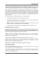
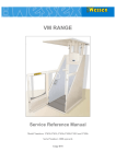
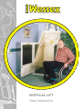
VERTICAL LIFT
User Instruction
CONTENTS
INTRODUCTION
VERTICAL LIFT - Illustration
Page No.
3
4
FEATURES - Standard
5&6
FEATURES - Optional
7&8
SAFETY PRECAUTIONS
9
OPERATING INSTRUCTIONS
Calling the lift to the required floor
Opening the door
Entering the car - seated model
Use of the sliding seat (if fitted)
Entering the car - wheelchair model
Closing the door
To travel to the required floor
Changing direction of travel
Vacating the lift
Alarm
Light
10
10
10
10
11
11
12
12
12
13
13
PROBLEMS OPERATING LIFT
Hydraulic pressure failure
Emergency lowering by lift car controls
Emergency lowering by pump unit controls
Emergency lowering button
14
14
14
14
DOOR FAILING TO OPEN
15
SERVICE AND INSPECTION
16
SPECIFICATION
17
ROUTINE CARE AND MAINTENANCE
18
EMERGENCY BREAKDOWN SERVICE
19
CHANGE OF USE
20
SERVICE AND INSPECTION RECORD
21
APPENDIX A - Periodic Examination Certificate
Page 2
22-26
INTRODUCTION
Thank you for buying the Wessex Vertical Lift. The Wessex range of lifts is the widest
available on the market and combines the latest technology and design making them easy
to use and aesthetically pleasing in the home, whilst offering long service and reliability.
Wessex has extensive experience in providing products that aid mobility and is the pioneer
of the majority of today’s domestic lifts. With this background and many years’ experience
in the manufacture and installation of Vertical Lifts, Wessex is clearly the most experienced
company in the market place. Our in-depth knowledge of associated building and electrical
work and management expertise ensures that installations are completed with the minimum
of inconvenience.
The instruction manual will help you become accustomed to your lift.
•
Study and become familiar with the step by step instructions.
•
Ensure that a nominated person is also familiar with the instructions, especially the
operating procedures in the event of a breakdown.
•
Keep the manual in a safe place for future reference together with the electrical wiring
diagram. A pocket is provided inside the lift for the purpose.
•
The door release key should always be kept clipped in its place inside the lift car.
IMPORTANT NOTICE - for Safe Use
In preparing the British Standard for Domestic Powered Lifts Wessex Medical believe that
BSI did not envisage the presence of unsupervised infants being left in the bedroom in which
the lift is installed. Certainly in such cases, we do not believe it would be appropriate to allow
an elevated car to be summoned from a remote call station.
Children should not be allowed to tamper or play with the lift or tracks. Joyriding is
dangerous. For extra safety switch off the keyswitch (optional extra) on the wall mounted
control stations, and remove key.
The area above and below the travel of the car must be kept clear at all times.
During travel do not impede the car or aperture board. Ensure that all persons, especially
children and pets, are kept clear of the lift prior and during travel. Obstacles must not be
placed on the aperture board or beneath the car.
Keep hands, etc. inside the lift at all times. Do not lean out of lift.
PRE PAYMENT METERS
British Standards (BS 5900) catergorically states that Powered Domestic Lifts shall not be
used in conjunction with a pre payment meter.
Wessex Medical support the principles laid out in the standard and recommends that lifts
should not be installed with a pre payment meter insitu and that there should not be any
change from a dedicated supply.
Page 3
VERTICAL LIFT ILLUSTRATION
Page 4
FEATURES - Standard
• ALARM
An audible alarm system is fitted and operated by a
push button switch on the car console. Also the switch
can be supplied as an option to operate a remote
mounted alarm either on the premises or linked to an
external telephone system.
• ALL ROUND VISION
High quality, fire resistant transparent panels are fitted
allowing a clear view of surroundings.
• APERTURE BOARD
If, during raising or lowering the lift, the aperture board
is impeded in any way, the lift will immediately STOP.
This is achieved through in built safety switches.
SENSITIVE SURFACE
• BATTERY BACKUP
FEATURES
In event of an electricity supply failure, the following
items within the lift will continue to function through a
battery backup system:
1.
2.
3.
4.
5.
6.
7.
• HARD WEARING
FLOOR COVERING
• CAR SENSITIVE EDGES/
SURFACES
• DOOR
Emergency Lowering Button
Relevant safety switches
Powered door
Stop
Alarm
Manual door lock
Integral lighting (one light only)
The interior floor area of the lift is fitted with a hard
wearing and easily cleaned floor covering.
If either the upper or lower sensitive edges of the car
are impeded in the direction of travel the lift will
immediately STOP. Again this is through in built safety
switches.
The lift will operate only if the door is properly closed
and locked. The door of the lift cannot be opened
BETWEEN floors (unless in an emergency - see ‘In the
event of the door failing to open’).
Page 5
FEATURES - Standard / Cont.
•
DOOR CLOSING
STRAP
Fitted as standard on wheelchair models without
powered doors.
•
ELECTRICITY TO CONTROL
A safe low voltage supply is used for all car controls.
•
EMERGENCY LOWERING
BY LIFT USER
An emergency lowering button is provided within the
lift should the lift stop due to a power cut or mains
failure. The in-car emergency lowering button will
illuminate and the pump motor will cut out.
•
EMERGENCY LOWERING
AT PUMP CONTROL
In the event of an emergency, means are provided to
permit the lift to be lowered. - See ‘Problems Operating
Lift’.
•
FIRE AND DRAUGHT SEAL
In accordance with BS5900, all models incorporate a
fire seal, which is effective when the car is parked at
the first floor level. Wessex therefore recommends that
the car be parked at the first floor when not in use.
•
GRAB HANDLES
Front or side mounting positions available. Front
handles fitted as standard on seated version.
•
HYDRAULIC PRESSURE
FAILURE
In the unlikely event of an oil pressure pipe failure, a
safety valve will immediately stop the lift.Refer to
‘Safety Precautions’.
•
ILLUMINATED CAR
CONTROLS
For ease of identification all in car push buttons are
illuminated. These buttons control all operations of the
lift.
•
LIGHTING
Internal illumination of the car, with battery backup is
provided by two low voltage switched lights at the
back of the car. Lights automatically switch off when lift
is not in use.
•
TELEPHONE
CONNECTION
Connection sockets for the fitting of a telephone are
provided as standard.
•
WALL MOUNTED CONTROL
STATIONS AT GROUND &
FIRST FLOOR LEVELS
Used to call the lift, or send it to its ‘parked’ position
away from current floor (if appropriate), and to operate
the powered door if fitted.
Page 6
FEATURES - Optional
•
SEAT VARIATIONS
For ease of access and personal preference, a
choice of 3 types of seating is available - bench,
perch (both these can be tipped up if/when not
required) and sliding (seated model only).
•
TELEPHONE HANDSET
This option is strongly recommended. Others must
fit telephone supply socket to the household for
connection to the lift.
•
POWERED DOOR
A push button switch on the lift console operates a
powered door. For safety, the door will immediately
STOP if obstructed and the lift will not operate.
(Available for
wheelchair models only).
LOCKING KEY SWITCHES
A 2-way personal key switching facility can be
provided.
Option 1 - 2-way key switched on both upper and
lower wall mounted call stations.
Option 2 - Lift-car mounted key switch to render incar push button console inoperative.
Page 7
FEATURES - Optional / cont.
• GRAB HANDLES
In wheelchair models grab handles can also be
offered as an option to assist mobility.
• LAP STRAP
A lap strap with an adjustable quick release buckle
can be offered to suit the range of seats.
• DOOR CLOSING STRAP
A braided, rope strap can be fitted inside the door to
assist closing. (Fitted as standard on manual door
models).
• AUTO HOMING
To ensure the lift always returns to the first floor level,
the car will automatically rise to the first floor after a
preset time from the door closing.
• AUTO DOOR CLOSING
To ensure the lift door always closes after a preset
(Powered Door Only) time after arrival at a landing
level.
• RADIO CONTROL
Remote operation of user lift functions.
Page 8
SAFETY PRECAUTIONS
•
OVERLOAD
Do not exceed the safe lifting capacity of the unit, which
is 225 kg (35 Stone).
•
SINGLE USER
It is strongly recommended that this lift be for a single
person either sitting down or in a wheelchair.
•
OBSTRUCTIONS
The area above and below the travel of the car must be
kept clear at all times.
During travel do not impede the car or aperture board.
Ensure that all persons, especially children and pets, are
kept clear of the lift prior and during travel. Obstacles
must not be placed on the aperture board or beneath
the car.
Keep hands, etc. inside the lift at all times. Do not
lean out of lift.
•
SEAT BELT
Where fitted, adjust length of buckle and always fit prior
to use of the lift.
•
DOOR OPENING
Do not attempt to force the door open during travel or
attempt to operate the lift with the door held closed. The
door should always be closed when not in use.
•
CHILDREN
Children should not be allowed to tamper or play with
the lift or tracks. Joyriding is dangerous. For extra safety
switch off the keyswitch (optional extra) on the wall
mounted control stations, and remove key.
•
FIRE SEAL
To form the mid floor fire seal it is essential that the lift is
parked at the first floor when not in use.
•
DOOR RELEASE KEY
The key should be available in car at all times.
•
LIFT MAINTENANCE
The manufacturer recommends that the lift is
serviced/checked every 6 months.
Note: Most hydraulic drive systems used for this type of product ‘settle’ when not in use over
a long period of time. With the car at ground level there is little effect, but at the first floor
level the car may drop by as much as 25mm (1 inch) before the self leveling system is
activated. This is perfectly normal and quite safe. This relevelling can occur even with the lift
door open and so may happen as you are entering / exiting the lift.
Page 9
OPERATING INSTRUCTIONS
•
CALLING THE LIFT
Insert and turn personal security key (If this option is
fitted) on wall control station at either ground or first
floor.
Press and release the appropriate push button.
The lift will automatically stop at entry level required.
Wall Control Station
•
OPENING THE DOOR – to enter the car
For manual opening of the door, depress the safety
edge as shown, and gently pull. For powered door
opening (optional extra) press the door-opening
button on the wall mounted call station.
All lights in the car will automatically illuminate.
Opening The Door
A powered door (if fitted) can be opened manually, if
this is done the door must be closed manually.
Note: Do not lean on the door safety edge without
opening the door otherwise the lift will not operate.
However the lift can be reset by opening / closing the
door
•
ENTERING THE CAR - Seated model.
Enter the car; use seat provided and fit seat belt (see
options).
Seated Model
Page 10
Use of sliding seat (Optional feature). Raise the seat
release lever located under the front of the seat and
pull forward until the release lever re-locks into
position. Transfer from the wheelchair onto the lift seat
and whilst seated, raise the release lever and slide
the seat to the back of the car until the release relocks.
OPERATING INSTRUCTIONS
•
ENTERING THE CAR - Wheelchair model.
It is recommended that you reverse the
wheelchair into the car wherever possible.
•
CLOSING THE DOOR - manual door option
Pull the braided rope gently provided on manual
doors to close the door (see door closing strap
option page 8). After opening there is a 5-second
delay of the automatic lock reset mechanism
before the door can be closed. The door must be
fully closed and locked before operating lift.
•
CLOSING THE DOOR – powered door option
Press the door-operating switch. The door will
close and lock.
Entering The Lift
Closing The Door
Lift Car Controls
It is not recommended that the powered door is
opened manually (only in emergency situations)
However, If the powered door is opened manually
it must be closed manually to re-engage the door
mechanism
Page 11
OPERATING INSTRUCTIONS
•
TO TRAVEL TO THE
REQUIRED FLOOR
The door must be fully closed and locked before
operating
the lift. The stop button
must be illuminated before
the lift will operate. There may be a small time delay after
Press and release the appropriate push
button
or
The stop button
travel.
•
CHANGING DIRECTION
OF TRAVEL
to travel.
can be used at anypoint during
If you wish to return to the floor you have departed from,
mid journey, stop the lift by pressing the stop button.
After a 3 second delay, the up, down and stop lights will
illuminate. Press and release the appropriate push button
with the direction of travel required marked on it, and the
lift will return to that floor. Alternatively, the original
direction can be maintained.
•
VACATING THE LIFT
Page 12
Move forwards and exit the lift after opening the door.
Close the door either manually or if using the powered
door option, use the door close switch on the wall
mounted call station. When not in use the lift should be
parked at first floor to ensure the fire seal between floors.
OPERATING INSTRUCTIONS
•
ALARM
In the event of emergency assistance required,
press and hold in the alarm button.
•
LIGHT
The 2 interior lift lights will illuminate:
-
by pushing the light
in the lift car.
‘push button’
-
or when the ‘door open switch’ is used.
- After calling the lift and after a period of 4 minutes,
the light will automatically go out. They will
illuminate when the door is operated.
•
AFTER USE
If fitted turn the personal key switch (on either wall
control station) to immobilise the lift. The key can
now be removed to prevent unauthorised use.
Ensure the door is closed.
Page 13
PROBLEMS OPERATING LIFT
In the event of a power failure whilst using the lift the following may be considered. However,
we strongly recommend that should a power failure occur when not in use the lift should not
be accessed or emergency lowered.
•
•
HYDRAULIC PRESSURE AND
•
•
EMERGENCY LOWERING
•
•
EMERGENCY LOWERING
BY PUMP UNIT CONTROL
ELECTRICAL POWER FAILURE
CONTROLS IN LIFT CAR
In the event of a power failure, the self-leveling
device will not function. A ‘Shoot Bolt’ safety
device restricts the distance the lift can creep
down from the first floor position. This position is
such that evacuation of the lift is possible at the
first floor level only by using the emergency k e y
to open the door (see page 15). The lift can only
be re-used when power returns.
First check the lift route and the ground floor are
clear of any obstructions. Next press the
illuminated emergency- lowering button on the
console. The lift will gently lower to the ground
floor where the user can vacate the car.
The emergency lowering facility can also operate
directly from the hydraulic pump unit.
First switch off the electrical supply at the switch
adjacent to the lift.
Open the hydraulic pump unit enclosure with the
key provided.
Push or pull and hold the valve button as shown.
The lift will gently lower to ground level. This
feature will not work if the lift is at the upper floor
level in which case the user can exit the lift
upstairs by opening the door
IMPORTANT SAFETY NOTE
Remove any obstructions and keep other
persons well clear before lowering as this
emergency method bypasses existing lift
safety systems.
Page 14
IN THE EVENT OF THE DOOR FAILING TO OPEN
Both manual and powered doors can be opened from the inside or outside of the car - by
using the door release key normally clipped on the inside of the lift car.
For safety reasons it is recommended that the door release key should normally be used
from outside of the car, by a third party assistant. It should never be used from inside the lift
car if it is not parked at the landing level.
•
To open the door, follow this procedure:
•
Ensure the lift is either positioned at the ground floor
or the upper floor landing level.
•
Place the key in the lock access hole in the door
panel and gently push (1) and lift up (2) as diagram.
•
Gently pull or push the door open whilst holding the
key.
SAFETY NOTE
In the interests of safety, please ensure that the DOOR RELEASE KEY is never left in
the lock access hole. To guard against this, the key is fitted with an integral spring.
NOTE:
We strongly recommend that you keep the key in a convenient place in case of
emergency - in the fixtures provided within the lift
Page 15
SERVICE AND INSPECTION
Your Vertical Lift has been inspected and tested to ensure safety and reliability. It should give
you many years of service as long as regular maintenance is correctly carried out. Failure to
do this could lead to unreliable or unsafe operation.
The lift is guaranteed for 12 months, unless you have decided to purchase an extended
warranty at the same time as buying your unit. Alternatively, you may wish to establish a
maintenance agreement that will provide for routine servicing on a regular basis thereafter.
Wessex recommends that the lift is checked/serviced every six months.
The lift must be serviced to the BS 5900 schedule, which includes checks on the following:
•
•
•
•
•
•
•
Suspension member checks
Safety interlock checks
Electrical integrity checks
Hydraulic pressure and safety valve checks
Hydraulic leakage checks - (e.g. hoses, fittings etc.)
Lubrication
Screws and nuts(as applicable)
A certificate similar to that shown in Appendix A should be prepared and recorded in a log
to be retained on site. The examining authority should retain a copy.
For all enquires regarding service please contact the Customer Service Department at:
WESSEX MEDICAL EQUIPMENT COMPANY LIMITED,
BUDDS LANE, ROMSEY, HAMPSHIRE SO51 0HA
TEL: 01794 830303
FAX: 01794 512621
Email: [email protected]
Website: www.wessexmedical.co.uk
Page 16
SPECIFICATION
All lifts comply fully with requirements of British Standard 5900:1999 ‘Specification for
Powered Domestic Lifts’ and CE marked in accordance with ‘The supply of Machinery
(safety) Regulations 1992. (for further information contact Wessex Medical Equipment
Company Limited).
STANDARDS
MODELS
DRIVE
LIFT CAPACITY 1 PERSON INCLUDING
WHEELCHAIR
POWER SUPPLY
CONTROL VOLTAGE
FINISH
POWER CONSUMPTION
BS 5900 (1999) specification for powered
domestic lifts
Rear hung seated or wheelchair
Hydraulic (direct acting ram)
225 Kg (35 Stone)
The supply shall be dedicated solely to the
lift and shall originate at the household
consumer unit, terminating at a double pole
control switch rated at 20 amps to BS3676.
Pre-payment meters are not allowed
24 Volts D.C.
Creamy White BS4800 - 10-B-15
toughened glass vision panels front and
side
1000 Watts normal
NOTE:
THE COMPANY RESERVES THE RIGHT TO ALTER THE SPECIFICATION WITHOUT
PRIOR NOTIFICATION TO MEET CONTINUED PRODUCT DEVELOPMENT
REQUIREMENTS.
Page 17
ROUTINE CARE AND MAINTENANCE
CAUTION
•
Before cleaning the Vertical Lift tracks and call station, please remember to switch off the
mains supply adjacent to the unit.
•
A variety of materials are used on the Vertical Lift and all lend themselves to ease of
cleaning with a damp not wet, non-abrasive cloth and a mild detergent such as washing
up liquid.
Avoid getting the aperture ‘in fill’ board wet since this may change the characteristics of
the board and affect it’s performance. This part must be considered when carrying out
maintenance checks A weakened trap board must be replaced.
•
A furniture polish and duster are recommended for the transparent panels but DO NOT
USE ABRASIVE CLEANERS.
•
Important Safety Notice
•
Do NOT under any circumstances paint the lift tracks as this could seriously impede
the
•
•
render the warranty void.
sliding mechanism and therefore the running of the lift. Additionally, such action will
Page 18
EMERGENCY BREAKDOWN SERVICE
NOTE: The following procedure is for units installed by Wessex Medical only. For
units installed by others please contact your local supplier.
Wessex Customer Service Department is manned between the hours of
8.30am to 5.15pm, Monday to Friday (except public holidays) and field
service engineers normally operate during the same hours.
An engineer will normally visit within 24 hours (Monday to Friday) to attend
to a breakdown call provided the equipment is covered by a warranty or the
user (or any agency responsible for a maintenance of the equipment) agrees
that they will cover any costs incurred.
Calls for assistance outside normal office hours will be handled by our
emergency cover service and every effort will be made to attend such calls
within a reasonable time scale (i.e. within 24 hours) - however there is no
guarantee that an engineer can be made available during these hours.
During normal office hour’s telephone the number indicated below and ask
for Customer Services. A member of staff will record details of your request
and initiate the necessary actions to resolve the problem.
Outside normal working hours telephone the number indicated below. This
will provide you with our emergency service number, which you must ring.
The operator will take details, and pass this information to the duty
supervisor who will then contact you by telephone to fully assess the
problem, and to offer a suitable level of technical assistance to minimise the
immediate difficulties being experienced. Where necessary and feasible, the
duty supervisor will make suitable arrangements for an engineer to attend
site as soon as possible to effect repairs.
In the event of a real emergency (e.g. lift stopping during travel with user on
the lift platform), and if it is not possible, for whatever reason, to manually
override the lift, our normal advice is to contact the emergency services (fire
brigade) to obtain immediate assistance.
For further information on breakdown cover and servicing please contact our
Customer Services Department.
EMERGENCY BREAKDOWN SERVICE
01794 830303
Page 19
CHANGE OF USE
Any change of use of the lift should be discussed with Wessex who will be able to
advise whether any alterations may be necessary.
Examples of such changes are:-
•
A change of type and weight of wheelchair
•
A change in the user’s disability
•
A change in user
•
An installation at another site
•
A change of duty cycle (number of journeys per hour)
WESSEX MEDICAL EQIPMENT COMPANY, BUDDS LANE, ROMSEY,
HAMPSHIRE, ENGLAND, SO51 0HA
TEL: 01794 830303
Part code: VM00 7100
Page 20
FAX: 01794 512621
Issue: F
Date: June 2004
SERVICE AND INSPECTION RECORD
SERVICE PERIOD
ENGINEER’S NAME
COMPANY
SIGNATURE / DATE
6 MONTHS
ONE YEAR
18 MONTHS
TWO YEARS
30 MONTHS
THREE YEARS
42 MONTHS
FOUR YEARS
54 MONTHS
FIVE YEARS
66 MONTHS
SIX YEARS
78 MONTHS
SEVEN YEARS
90 MONTHS
EIGHT YEARS
102 MONTHS
NINE YEARS
114 MONTHS
TEN YEARS
Page 21
APPENDIX A
VERTICAL LIFT
PERIODIC EXAMINATION CERTIFICATE
NOTE: Statements and replies to the relavant question should be annotated in the appropriate boxes. Where
‘yes’ or ‘no’ replies are necessary the appropriate box only should be ticked.
1 Premises
(a) Occupier (or owner) of Premises:
(b) Address of premises:
2 Lift Data
(a) Type of lift:
(b) Lift serial no:
(c) Description of Lift:
(d) Date of construction or reconstruction
(if ascertainable):
3 Construction of lift
Are all parts of the lift of good mechanical construction,
Yes
No
sound material and adequate strength (so far as is
ascertainable):
NOTE: Details of any renewals or alterations should be given in 6 and 7 below.
Page 22
APPENDIX A
4 Condition of lift
Are the following parts of the lift properly maintained and in good working order? If no, state what defects have
been found.
1)
1)
1)
1)
(a) Car doors
Yes
No
(b) Interlocks on car doors:
Yes
No
(c) Other door fastenings:
Yes
No
(d) Car and fittings, car and
counterweight guides:
Yes
No
(e) Over running devices:
Yes
No
(f) Suspension ropes and their
attachments:
Yes
No
If applicable
Page 23
APPENDIX A
1)
1)
1)
(g) Safety gear and overspeed governor (i.e.
arrangements for preventing fall of the car
and the counterweight):
Yes
No
(h) Hydraulic valves:
Yes
No
(i) Safety circuits, fuses and other
electrical equipment:
Yes
No
(j) Other part e.g. hydraulic fluid
level:
Yes
No
5 Accessibility
What parts (if any) were ‘inaccessible?
1)
If applicable.
Page 24
APPENDIX A
6 Repairs, renewals or alterations
What repairs, renewals or alterations are required to enable the lift to continue to be used with safety?
(a) Immediately:
(b) Within a specified time limit:
Specified time limit:
NOTE: If no such repairs, renewals or alterations are required enter ‘none’.
7 Defects
What defects (other than those in 6) require attention?
8 Safe working load
Subject to the repairs, renewals or alterations (if any) stated in 6, what is the maximum safe working load of
the lift?
kg
9 Other observations
Page 25
APPENDIX A
10 Declaration
I/We certify that on
I/We thoroughly examined this lift and that the
foregoing is a correct report of the result.
Signature(s):
Position:
Service Engineer
Address(es):
Budds Lane
Romsey
Hampshire
SO51 0HA
Date:
Page 26
Service Engineer
Part code: VM00 7100
Issue :E
Date: January 2002
Wessex Medical Equipment Company Limited
Budds Lane, Romsey, Hampshire, England SO51 0HA
Tel: +44 (0)1794 830303 Fax: +44 (0)1794 512621
E-mail: [email protected]
Website: www.wessexmedical.co.uk
ISO 9001
FM 58435
CE Marked in compliance
with European Regulations
A Member of the Ratcliff Group
The Wessex Policy is one of continuous product development and the Company therefore reserves the right to alter product or component specifications without notice