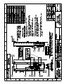
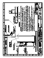
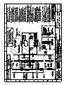
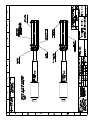
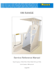
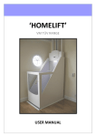
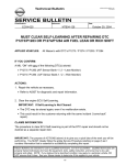
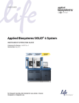
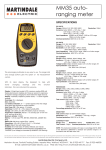
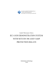
1
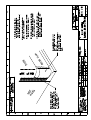
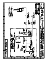
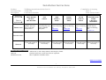
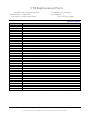
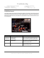
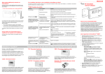
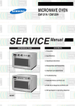
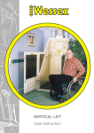
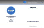
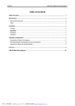
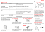
SECTION 6
Hydraulics
Hydraulic Section Contents
Product: VM Service Procedure
Document Ref: VM00 5670
Description: Hydraulic Section Contents
Compiled by: K.Farthing
Issue: 2
Date: 08 March 2007
Return to contents
1. Hydraulic Ram Change Procedure
2. Hydraulic Ram Bleed Procedure
3. Hydraulic Circuit Drawing
Section 6
Wessex Lift Co Ltd, Budds Lane, Romsey, Hampshire, SO51 0HA
Hydraulic Ram Change Procedure
Product: VM Service Manual
Document Ref: VM00 5680
Description: Ram Change Procedure
Compiled by: K.Farthing
Issue: 2
Date: 08 March 2007
Return to contents
RAM CHANGE PROCEDURE
REFER TO THE INSTALLATION / SERVICE REFERENCE FOLDER FOR SPECIFIC SETTING
INSTRUCTIONS.
The following documents should be available and referred to whilst changing the ram;
Top and Bottom Carriage Sliders Setting Instruction VM00 2030
Ram Housing Setting Instruction VM00 2020
Bleed Procedure for Lift
Specialist Tools Required
2 off bleed pipes
2 off plastic tubes (rollers) approx. 100mm dia, wall thickness 3mm + to move lift.
Absorbent cloths in case of fluid spillage.
Warning Be aware that trapping / shearing / lifting hazards will be prevalent during moving of the lift car and
ram when partially dismantled. Also, familiarise yourself with our documents “Safety Whilst Working On The
Lift” and “Safety And Hydraulic Systems”. It is recommended that ram changes be carried out by at least 2
persons, one of whom is a competent Lift Engineer.
1.1
1.2
Remove rear panels of the lift.
Remove the extensions fitted to the rear LH and RH of the floating platform.
2.1
Remove the 2 off M5 screws that secure the left-hand side of the ram-housing upper to the structural
beam. Slacken (but do not remove) the 1 off M5 screw holding the right-hand side of the ram hosing
upper to the structural beam.
Gently lower the ram-housing upper to the ground.
Remove the bottom limit switch cam from the inside face of the lower end of the LH track, it is
advised to mark its position first.
2.2
2.3
3.1
3.2
3.3
3.4
3.5
4.1
4.2
4.3
4.4
4.5
With the lift raised approx. 300mm above the ground floor.
Pull floating platform down from the lift car.
Apply a small g-clamp (or similar) to each platform rope close to where the rope exits beneath the lift
side frames (this will prevent the ropes retracting into the lift car).
Detach the floating platform from the lift by carefully cutting the cable ties from around each rope end
ferrule and disconnecting the wire rope from its retainer in the platform.
Place the 2 off roller tubes width ways beneath the lift, one approx. 100mm from the front of the lift
and one approx. 100mm from the rear of the lift.
Cautiously lower the lift onto the tubes.
With the lift fully supported on the tubes.
Slacken the M8 HEX. HD. Screws holding the slider stabiliser rear (VM30 0244, see drawing VM00
2030 sheet 2) and move the sliders inboard.
Remove the M8 HEX. HD. Screws holding the top slider brackets (VM30 0247, see drawing VM00
2030 sheet 1) and remove the brackets.
Remove the M6 screws and spacer holding the ram cover slide to the front of the ram. Lower the
cover down.
Remove the M10 socket cap screw securing the ram head to the carriage, taking care not to lose the
ram head swivel.
Lower the ram clear from the carriage by using the emergency lower valve.
1
Section 6
Wessex Lift Co Ltd, Budds Lane, Romsey, Hampshire, SO51 0HA
Hydraulic Ram Change Procedure
Product: VM Service Manual
Document Ref: VM00 5680
Description: Ram Change Procedure
4.6
4.7
4.8
4.9
5.0
5.1
5.2
5.3
5.4
5.5
Compiled by: K.Farthing
Issue: 2
Date: 08 March 2007
Gently roll the lift car clear of the tracks; ensure that the trailing cable is not stretched, if necessary
disconnect this from the lift car.
Slacken and then remove the ram height adjusters (remove 8 off M8 locknuts first) that hold the ram
housing to the structural beam.
Remove the 8 off M8 x 16 HEX. HD screws (4 each side) from the sides of the ram housing.
Lower the ram housing fully and ensure that there is no hydraulic pressure left in the system.
Be prepared to contain any fluid spillage.
Disconnect the hydraulic supply hose from the base of he ram.
Remove the ram and ram housing to a clear area.
Remove and set aside, for re-use, the fittings from the base of the ram.
Fit a blanking plug to the base of the ram to prevent leakage during transportation.
Remove the ram from the housing.
Refitting of the replacement ram
Refitting is the reverse of the removal sequence; however, the following should be noted;
Use new Dowty Seals as a matter of routine.
Bleed the ram before fitting the upper ram housing.
Top up the fluid reservoir on completion.
The ram can be extended to meet the carriage by careful use of the contactor within the PSU box.
Refit the ram and housing by making specific reference to the ram-housing setting instruction (VM00
2020).
• It is imperative that the M10 socket cap screw securing the ram head to the carriage is refitted correctly.
• Refit the lift to the tracks with particular reference to the top and bottom carriage sliders setting
instruction (VM00 2030).
• When refitting the floating platform use new cable ties around the rope ferrules.
• Ensure that the bottom limit switch cam is refitted and that the limit switches operate correctly, refer to
setting instruction VM00 2100.
On completion check that all the lift safety circuits function correctly and that the lift is running smoothly.
•
•
•
•
•
2
Wessex Lift Co Ltd, Budds Lane, Romsey, Hampshire, SO51 0HA
Section 6
Hydraulic Ram Bleed Procedure
Product: VM Service Manual
Document Ref: VM00 5690
Description: Bleed Procedure
Compiled by: K.Farthing
Issue: 2
Date: 08 March 2007
Return to contents
Hydraulic Ram Bleed Procedure
REFER TO THE INSTALLATION / SERVICE REFERENCE FOLDER FOR SPECIFIC SETTING
INSTRUCTIONS.
WARNING The utmost care must be taken as the lift will be moved with the rear panels removed and
trapping / shearing hazards will be exposed.
The bleeding of the ram should be carried out with the car stopped at the lowest level. Prior to bleeding it is
necessary to lower the ram-housing upper to expose the bleed nipples.
1.0
Remove the rear panels of the lift.
2.0
When the lift car and trap board are partially raised remove the 2 off M5 screws that secure the lefthand side of the ram-housing upper to the structural beam. Slacken (but do not remove) the 1 off M5
screw holding the right hand side of the ram housing upper to the structural beam.
3.0
Gently lower the ram- housing upper to the ground.
4.0
Cautiously lower the lift car to the ground.
5.0
From inside the car remove both bleed nipple dust caps.
6.0
Connect bleed hoses to both bleed nipples and secure using clips provided.
7.0
Immerse the other end of the bleed hoses in clean hydraulic fluid in a jar.
8.0
Start the pump. Raise the lift approx. 50mm. Fluid will pass through at low pressure into the jar and
the car will lower. Watch for air bubbling in the jar.
9.0
Repeat the above until fluid clear of air passes into the jar.
10.0
Remove the bleed hoses and refit the nipple caps.
11.0
Refill the fluid reservoir.
12.0
Raise the lift approx. 200mm and ensure lift is not creeping down.
13.0
Refit the ram-housing upper to the structural beam.
14.0
Refit the rear panels to the lift.
Section 6
Wessex Lift Co Ltd, Budds Lane, Romsey, Hampshire, SO51 0HA
SECTION 7
Lubrication Schedule
Installation Instructions
Product:
Document Ref:
Description:
Item to be
lubricated
Time of
application
PRODUCTION
VM Range manufactured after Jan 99
VM30 5010
Lubrication Schedule
TRAP BOARD
PICK UP
MECHANISM
Apply grease to the
plunger, tube and
faces of the trap
board socket
GAS
STRUT
Grease plunger
beneath spring, also
guide welded to
side panel
Compiled by: K.Farthing
Issue: 6
Date: 08 March 2007
SIDE
SAFETY
EDGE
DOOR
SAFETY
EDGE
REAR
SAFETY
EDGE
Refer to Drawing
No.
Refer to Drawing
No.
Refer to Drawing
No.
VM00 2050
VM00 2060
VM00 2070
POWER DOOR
GUIDE
CHANNEL
ASSEMBLY
Apply grease to
Guide channel.
Refer to Drawing
No.
VM00 2130
INSTALLATION
SERVICE
Clean and reapply if
necessary
Clean and reapply
if necessary
Clean and reapply
if necessary
Clean and reapply
if necessary
Clean and reapply
if necessary
Clean and reapply if
necessary
SUGGESTED LUBRICANTS
SPRAY LUBRICANT
Ambersil 40+ (CM31 1000), WD40, Loctite Repel or similar
GREASE
Lithium Grease EP2, Castrol LM Grease or equivalent
HYDRAULIC OIL
ISO 32 Hydraulic oil (MM31 5001)
Return to contents
1
Section 7
Wessex Lift Co Ltd, Budds Lane, Romsey, Hampshire, SO51 0HA
Installation Instructions
Product:
Document Ref:
Description:
Item to be
lubricated
Time of
application
PRODUCTION
VM Range manufactured after Jan 99
VM30 5010
Lubrication Schedule
FLOOR:
ROLLER
ASSEMBLY
DOOR
HINGES
Apply light coat of
grease to pin before
assembly
Apply Grease
to hinge pivot
point
DOOR
LINK
ARM
Clean and reapply if
necessary
DOOR LATCH & KEY
MECHANISM
(VM10 0681 &
VM 0606)
RAM
DOOR
FLAP
Grease
hinges
Apply grease to pivot rod
before inserting into
bracket on side panel
INSTALLATION
SERVICE
Compiled by: K.Farthing
Issue: 6
Date: 08 March 2007
Clean and reapply if
necessary
Apply thin film of
grease to mechanism
and ensure burr free.
Clean and check for
signs of burring remove
if necessary, re-apply
thin film of grease.
(Report burring problem
if present to
engineering)
Apply hydraulic
oil to cylinder if
required
(dependent on
supplier of ram)
Clean and
reapply if
necessary
SUGGESTED LUBRICANTS
SPRAY LUBRICANT
Ambersil 40+ (CM31 1000), WD40, Loctite Repel or similar
GREASE
Lithium Grease EP2, Castrol LM Grease or equivalent
HYDRAULIC OIL
ISO 32 Hydraulic oil (MM31 5001)
2
Section 7
Wessex Lift Co Ltd, Budds Lane, Romsey, Hampshire, SO51 0HA
SECTION 8
Replacement Parts
VM Replacement Parts
Product: VM Service Documents
Document Ref: VM00 5700
Description: Replacement Parts
Compiled by: K.Farthing
Issue Number: 3
Date: 08 March 2007
Return to contents
PART NUMBER
DESCRIPTION
EC08 1502
EC06 2010
EC07 0006
EC07 0007
EC07 0017
EC07 0020
EC08 1501
EC08 1504
EC08 1517
EC08 1518
EC08 3003
EC08 3028
EC08 3029
EC08 4500
EC08 4501
EC08 4502
EC08 4503
EC12 0014
HC20 0200
HC20 0300
HC23 0200
HC23 0202
HC23 0203
HC23 0204
HC44 0200
HC53 8002
MC10 8022
MC10 8023
MM21 2000
EC04 2011
EC04 2007
HC00 1010
HC00 1012
MM31 0014
MM35 0031
PT04 0004
EC08 4504
MAIN PCB (See specific PCB for part number)
SWITCH MICRO BVMFYR
INCANDESCENT BULB (Pre 7000 serial number)
FUSE 3.15A A/S LBC 20MM GLASS
FUSE 5A A/S LBC 20MM GLASS
FUSE 10A S/D LBC 20MM GLASS
FUSE 10A HBC CERAMIC
SWITCH MICRO BVM3FYR1
SWITCH 2VCFQR1(Pre 7000 serial number)
SWITCH MICRO VCFQ2
SWITCH LIMIT XG2-S20
SWITCH LIMIT BVM3FQ1
SWITCH FINAL LIMIT KB5 EQ
SWITCH VCFQR1 (Pre 7000 serial number)
REED SWITCH DOOR CLOSE LIMIT
MAGNET REED SWITCH DOOR CLOSE LIMIT
REED SWITCH TRAP ASSEMBLEY
MAGNET REED SWITCH TRAP ASSEMBLEY
BULB 24V 10W (Pre 7000 serial number)
DOWTY WASHER ¼ BSP
DOWTY WASHER ⅜ BSP
BANJO BOLT
BANJO SWAGE FITTING
ADAPTER ¼ BSP TO ⅜ BSP MALE
ADAPTER 90ᑻ ELBOW
ADAPTER ¼ BSP FEMALE
BLEED NIPPLE
SAVORY PUMP A/V MOUNT PART 1
SAVORY PUMP A/V MOUNT PART 2
RUBBER DOOR BUFFER SELF ADHESIVE
SOLENOID SHOOT BOLT
SOLENOID DOOR LATCH
HYDRAULIC RAM. TRAVEL UP TO 3 METRES
HYDRAULIC RAM. TRAVEL UP TO 3.5 METRES
VELCRO PANEL PADS. SELF ADHESIVE
GAS STRUT
DOOR ACTUATOR
REED SWITCH DOOR OPEN LIMIT(Serial number 7000 onwards)
1
Wessex Lift Co Ltd, Budds Lane, Romsey, Hampshire, SO51 0HA
Section 8
VM Replacement Parts
Product: VM Service Documents
Document Ref: VM00 5700
Description: Replacement Parts
Compiled by: K.Farthing
Issue Number: 3
Date: 08 March 2007
PART NUMBER
DESCRIPTION
EC08 3037
EC103031
EC12 0018
VMOP 1092
MC04 1035
MC04 1050
EC14 3005
MM35 0031
VM30 8046
VM50 8004
EC14 5006
SWITCH LIMIT/ANTI-CREEP/OVERTRAVEL (Serial number 7000 onwards)
GROMET WHITE DOOR SAFETY EDGE AND LOWER CABLE COVER
HALOGEN LAMP 24V 20W (Serial number 7000 onwards)
IN-CAR KEY SWITCH
SPRING COMPRESSION. FLOATING PLATFORM VM30/50 ALSO ALL TRAPS
SPRING COMPRESSION. FLOATING PLATFORM VM31/51/36/56
BATTERY 12V 1.2AH(Serial number 7000 onwards)
GAS STRUT
LOOM TRAILING CABLE VM30 RANGE(Serial number 7000 onwards)
LOOM TRAILING CABLE VM50 RANGE (Serial number 7000 onwards)
TELEPHONE
2
Wessex Lift Co Ltd, Budds Lane, Romsey, Hampshire, SO51 0HA
Section 8
SECTION 9
Troubleshooting
Troubleshooting
Product: VM Service Documents
Document Ref: VM00 5710
Description: Troubleshooting
Compiled by: K.Farthing
Issue Number: 2
Date: 08 March 2007
Using the LED indicators on the circuit board it is usually possible to trace a fault down to a circuit quite
quickly.The Descriptions below are intended as a guide only and should be used in conjunction with the
relevant circuit and schematic diagrams.
First Checks
If the stop and door interlock LED’s are illuminated the lift should be ready to travel.See Fig 1
Use the table below to establish the LED status and fault indications if the lift will not run.The photographs
below show the LED’s and their normal running condition.
Fig 1
Stop and Door Interlock LED’s are normally lit
Fig 2
Fig 3
Door interlock fail LED should not be lit
LED STATUS
LD4 Not lit
LD5 Not lit
Zone switch fail LED should not be lit
DESCRIPTION
POSSIBLE CAUSE
Stop Circuit Fig 1
Door Interlock Fig 1
LD25 Lit
Door Interlock Fail Fig 2
LD26 lit
Zone SW Fail Fig 3
Check key switches and locking stop buttons.
Check the door latch interlock switch and the
magnetic reed switch.
Ensure the door latch is not stuck up.Check that
the door interlock switch is functioning correctly.
Check that the user is not pushing down on the
door safety edge as they are closing the door.
Check that the lower floor limit is not stuck
in.Check that the lower floor limit is not off the
stop plate with the zone switch still engaged.
1
Wessex Lift Co Ltd, Budds Lane, Romsey, Hampshire, SO51 0HA
Section 9
Troubleshooting
Product: VM Service Documents
Document Ref: VM00 5710
Description: Troubleshooting
Compiled by: K.Farthing
Issue Number: 2
Date: 08 March 2007
Lift Will Not Descend
If the lift will not descend after the above checks have been carried out the fault may be in one of the control
surfaces on the lift. When the down button is pushed all 3 LED’s shown in fig 4 should illuminate.If the lift will
not travel push and hold the down button whilst observing the LED’s.Use the table below to determine the
possible cause if any of the LED’s are not illuminated. LD 8,when lit, indicates that the down button is being
pushed.
Fig 4
All 3 LED’s should illuminate when down button pushed
LED STATUS
DESCRIPTION
POSSIBLE CAUSE
LD12 not lit
LD13 not lit
Floating Platform
Trap Assembly
Check the floating platform down safety switches
and the wiring from the switches to the Circuit
Board.All switches should be normally closed.
LD 13 not lit
Trap Assembly
Check the trap down safety switches and the
wiring from the switches to the circuit board. All
switches should be normally closed.
2
Wessex Lift Co Ltd, Budds Lane, Romsey, Hampshire, SO51 0HA
Section 9
Troubleshooting
Product: VM Service Documents
Document Ref: VM00 5710
Description: Troubleshooting
Compiled by: K.Farthing
Issue Number: 2
Date: 08 March 2007
Lift Will Not Ascend
If the lift will not ascend after the checks on the previous page have been carried out the fault may be in one
of the control surfaces on the lift. When the up button is pushed all 4 LED’s shown in fig 5 should illuminate.
If the lift will not travel push and hold the up button whilst observing the LED’s.Use the table below to
determine the possible cause if any of the LED’s are not illuminated. LD7,when lit, indicates that the up button is being pushed.
Fig 5
All 4LED’s should illuminate when up button pushed
LED STATUS
DESCRIPTION
POSSIBLE CAUSE
LD 9 not lit
LD10 not lit
LD11 not lit
Floating Platform
Car Safety Edges
Trap Assembly
Check the floating platform up safety switches
and the wiring from the switches to the Circuit
Board. All switches should be normally closed.
LD10 not lit
LD11 not lit
Car Safety Edges
Trap Assembly
Check the lift car safety edge switches and all
wiring back to the Circuit Board. All switches
should be normally closed.
LD 11 not lit
Trap Assembly
Check the trap up safety switches and the wiring
from the switches to the circuit board. All switches
should be normally closed.
3
Wessex Lift Co Ltd, Budds Lane, Romsey, Hampshire, SO51 0HA
Section 9
SECTION 10
AMENDMENT RECORD
Document Amendment Record
Product: VM Range
Document Ref: VM00 5720
Description: Amendment Record
Compiled by: K.Farthing
Issue: 2
Date: 08 March 2007
Return to contents
Date
Amendment Details
Reference Number
1
Wessex Lift Co Ltd, Budds Lane, Romsey, Hampshire, SO51 0HA
Section 10