1
O
Operating Manual (Safety PLC)
Operating Manual
(Safety PLC)
GX Developer Version 8 Operating Manual (Safety PLC)
MODEL
GXDEV8-O-SAF-E
MODEL
CODE
13JU53
SH(NA)-080576ENG-A(0609)MEE
HEAD OFFICE : TOKYO BUILDING, 2-7-3 MARUNOUCHI, CHIYODA-KU, TOKYO 100-8310, JAPAN
NAGOYA WORKS : 1-14 , YADA-MINAMI 5-CHOME , HIGASHI-KU, NAGOYA , JAPAN
When exported from Japan, this manual does not require application to the
Ministry of Economy, Trade and Industry for service transaction permission.
Specifications subject to change without notice.
SW8D5C-GPPW-E
G
• SAFETY PRECAUTIONS •
(Always read these instructions before using this equipment.)
Before using this product, please read this manual and the relevant manuals introduced in this manual
carefully and pay full attention to safety to handle the product correctly.
The instructions given in this manual are concerned with this product. For the safety instructions of the
programmable controller system, please read the CPU module user's manual.
In this manual, the safety instructions are ranked as "DANGER" and "CAUTION".
DANGER
Indicates that incorrect handling may cause hazardous conditions,
resulting in death or severe injury.
! CAUTION
Indicates that incorrect handling may cause hazardous conditions,
resulting in medium or slight personal injury or physical damage.
!
Note that the ! CAUTION level may lead to a serious consequence according to the circumstances.
Always follow the instructions of both levels because they are important to personal safety.
Please save this manual to make it accessible when required and always forward it to the end user.
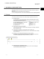
[Design Instructions]
!
DANGER
• When data/program change, or status control is performed from a PC to a running safety PLC,
create an interlock circuit outside the sequence program and safety PLC to ensure that the
whole system always operates safely.
For the operations to a safety PLC, pay full attention to safety by reading the relevant manuals
carefully, and establishing the operating procedure.
Furthermore, for the online operations performed from a PC to a safety CPU module, the
corrective actions of the whole system should be predetermined in case that a communication
error occurs due to a cable connection fault, etc.
• When a safety remote I/O module has detected a CC-Link Safety error, it turns off all the
outputs.
Note that the outputs in a ladder program are not automatically turned off.
If a CC-Link Safety error has been detected, create a ladder program that turns off the outputs
in the program.
If the CC-Link Safety is restored with the outputs on, it may suddenly operate and result in an
accident.
• To inhibit restart without manual operation after safety function was performed and outputs
were turned OFF, create an interlock program which uses a reset button for restart.
A-1
A-1
[Startup/Maintenance Instructions]
!
CAUTION
• The online operations performed from a PC to a running safety PLC (Program change when a
safety CPU is RUN, device test, and operating status change between RUN and STOP) have
to be executed after the manual has been carefully read and the safety has been ensured.
Following the operating procedure predetermined at designing, the operation has to be
performed by an instructed person.
When changing a program while a safety CPU is RUN (Write during RUN), it may cause a
program breakdown in some operating conditions.
Fully understand the precautions described in the GX Developer's manual before use.
A-2
A-2
REVISIONS
The manual number is given on the bottom left of the back cover.
Print Date
Sep., 2006
Manual Number
Revision
SH(NA)-080576ENG-A First edition
Japanese Manual Version SH-080575-A
This manual confers no industrial property rights or any rights of any other kind, nor does it confer any patent licenses.
Mitsubishi Electric Corporation cannot be held responsible for any problems involving industrial property rights which
may occur as a result of using the contents noted in this manual.
© 2006 MITSUBISHI ELECTRIC CORPORATION
A-3
A-3
INTRODUCTION
Thank you for choosing the Mitsubishi MELSOFT series Integrated FA software.
Please read this manual and make sure you understand the functions and performance of MELSEC series
sequencer thoroughly in advance to ensure correct use.
Please make this manual available to the end user.
CONTENTS
SAFETY PRECAUTIONS.............................................................................................................................A - 1
REVISIONS ...................................................................................................................................................A - 3
INTRODUCTION...........................................................................................................................................A - 4
CONTENTS...................................................................................................................................................A - 4
MANUALS .....................................................................................................................................................A - 6
HOW TO SEE THE MANUAL ......................................................................................................................A - 7
ABBREVIATIONS AND TERMS IN THIS MANUAL....................................................................................A -10
Chapter 1 GENERAL DESCRIPTION
1- 1 to 1- 30
1.1 Features................................................................................................................................................... 1- 1
1.1.1 Access level...................................................................................................................................... 1- 2
1.1.2 User registration and login certification ........................................................................................... 1- 3
1.1.3 CPU access password..................................................................................................................... 1- 4
1.1.4 Safety CPU operation mode (Safety mode and test mode) ........................................................... 1- 5
1.1.5 Operation lock .................................................................................................................................. 1- 5
1.2 Functions Lists ........................................................................................................................................ 1- 6
1.2.1 Functions lists ................................................................................................................................... 1- 6
1.2.2 Restricting operations by using safety CPU operation mode/access level .................................... 1-22
Chapter 2 SYSTEM CONFIGURATION
2- 1 to 2- 2
Chapter 3 RESTRICTIONS AND PRECAUTIONS
3- 1 to 3- 2
3.1 Precautions for the GX Developer Version Earlier than the Safety CPU Compatible Version ............ 3- 1
3.2 Precautions for Management.................................................................................................................. 3- 2
Chapter 4 PROCEDURES TO OPERATION
4- 1 to 4- 2
4.1 When Creating a Safety Project .............................................................................................................. 4- 1
4.2 When Modifying the Safety Project in Operation .................................................................................... 4- 2
Chapter 5 ADDED FUNCTIONS TO CORRESPOND TO A SAFETY PLC
5- 1 to 5-37
5.1 Security Operations.................................................................................................................................. 5- 1
5.1.1 Registering the user when creating a new project ........................................................................... 5- 1
5.1.2 Registering/deleting/changing a login user ...................................................................................... 5- 3
5.1.3 Logging in to a project....................................................................................................................... 5- 9
5.1.4 Locking operations ........................................................................................................................... 5-11
A-4
A-4
5.2 Safety CPU Operation ............................................................................................................................ 5-15
5.2.1 Switching safety CPU operation mode............................................................................................ 5-15
5.2.2 Displaying ROM information ............................................................................................................ 5-16
5.2.3 Registering or changing a CPU access password.......................................................................... 5-18
5.2.4 PLC memory initialization................................................................................................................. 5-21
5.2.5 Switching the CPU to be monitored................................................................................................. 5-22
5.3 Detecting the Damaged Project Data..................................................................................................... 5-23
5.4 Highlighting Safety Devices .................................................................................................................... 5-25
5.5 Setting Parameters ................................................................................................................................. 5-28
5.5.1 Setting the parameters for a safety CPU......................................................................................... 5-28
5.5.2 Setting the parameters for the CC-Link Safety master module...................................................... 5-30
5.6 Diagnosing a Safety PLC........................................................................................................................ 5-33
5.7 Writing Program Memory to ROM .......................................................................................................... 5-37
APPENDICES
Appendix- 1 to Appendix-10
Appendix 1 Differences with the Q Series Project ...........................................................................Appendix- 1
Appendix 2 Functions for which CPU Access Password Certification is Performed ......................Appendix- 9
Appendix 3 ASCII Code Table..........................................................................................................Appendix-10
INDEX
A-5
Index- 1 to Index- 2
A-5
MANUALS
Introductory Manual
Make sure to read the following manual before configuring/designing a safety system.
Manual Name
Safety Application Guide
Explains the overview and construction method of the safety system, laying and wiring
examples, application programs and others.
(Sold separately.)
Manual No.
(Model Code)
SH-080613ENG
(13JR90)
Related Manuals
The following lists the manuals for this software package.
Refer to the following table when ordering manuals.
Manual Name
GX Developer Version 8 Operating Manual
Explains the online functions of the GX Developer, such as the programming, printout,
monitoring, and debugging methods.
(Sold separately.)
Manual No.
(Model Code)
SH-080373E
(13JU41)
GX Developer Version 8 Operating Manual (Startup)
Explains the system configuration, installation and starting methods of the GX Developer.
(Sold separately.)
SH-080372E
(13JU40)
QSCPU User's Manual (Function Explanation, Program Fundamentals)
Explains the functions, programming methods, devices and others that are necessary to
create programs with the QSCPU.
(Sold separately.)
SH-080627ENG
(13JR93)
QSCPU Programming Manual (Common Instructions)
Explains how to use the sequence instructions, basic instructions, and QSCPU dedicated
instructions.
(Sold separately.)
SH-080628ENG
(13JW01)
CC-Link Safety System Master Module User's Manual
QS0J61BT12
Explains the specifications, procedures and settings up to operation, parameter settings and
trouble shootings of the QS0J61BT12-type CC-Link Safety system master module.
(Sold separately.)
SH-080600ENG
(13JR88)
CC-Link Safety System Remote I/O Module User's Manual
QS0J65BTB2-12DT
Explains the specifications, procedures and settings up to operation, parameter settings and
trouble shootings of the CC-Link Safety Remote I/O Module.
(Sold separately.)
SH-080612ENG
(13JR89)
REMARK
Printed materials are separately available for single item purchase. Order the
manual by quoting the manual number on the table above (Model Code).
A-6
A-6
2
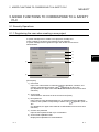
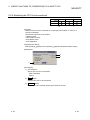
HOW TO SEE THE MANUAL
The availability of the menu selection/operation, differs depend on the combination
of safety CPU operation mode and an access level, is described. (
(1))
The restriction on the
setting/operation is
described. (
(1))
What to set in
the section is
described.
Following the
direction, open
the setting screen.
The screen for the
setting is indicated.
The numbered items
are described in
[Description].
The items and
buttons numbered
in [Dialog Box]
are described.
Reference:
The Chapter or Section
including the relative
explanation is indicated.
This gives the information related to the topic
discussed and also the helpful information.
A-7
A-7
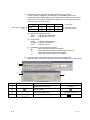
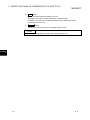
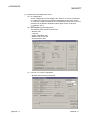
(1) Availability of menu selection/operation (Upper right of the page)
In each operation explained in the Chapter 5, the availability of the menu
selection/operation, differs depend on the combination of safety CPU operation
mode and an access level, is listed as the table below on the upper right corner
of the first pages for each section.
Admin.
Safety CPU operation
mode
{
Develop.
Access level
Users
}
Safety
Test
Availability of menu
selection/operation
(a) Safety CPU operation mode
Safety
: Indicates the safety mode.
Test
: Indicates the test mode.
(b) Access level
Admin. : Indicates "Administrators".
Develop. : Indicates "Developers".
Users
: Indicates "Users".
(c) Availability of menu selection/operation
: Menu selection/operation is available.
: Menu selection/operation is available with restrictions.
Restrictions are described under the table.
: Menu selection/operation is not available.
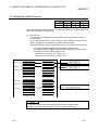
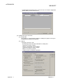
(2) Symbols used for GX Developer screen and function explanation
Symbols used in this manual, and their contents and examples are shown below.
1)
2)
3)
4)
No.
1)
Symbol
[
]
2)
3)
4)
A-8
Contents
Menu name of menu bar
Example
[Project]
Icon in toolbar
<<
>>
Tab name of dialog box
Command button in dialog box
<<Program common>>
lOKl button
A-8
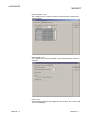
(3) Functions that cannot be operated by GX Developer
The functions that cannot be operated using the GX Developer are grayed
(masked) and cannot be selected. There are the following reasons why they are
not selectable.
(a) The PLC CPU used does not have the functions.
For example, when the QSCPU is chosen in the "PLC series", selecting the
[Project] [Change PLC type] is disabled since the QSCPU does not have
another PLC type.
To see if the PLC CPU has the operable functions, refer to the
specifications in the PLC CPU User's Manual.
(b) The functions that cannot be selected because they cannot be used with
the currently operated function.
For example, when the monitor screen is open, Change PLC type, Transfer
setup, Change PLC data attributes, Marge data, Check parameter, and
Clear all parameters cannot be performed.
A-9
A-9
ABBREVIATIONS AND TERMS IN THIS MANUAL
This manual uses the abbreviations and terms listed in the following table to discuss
the GX Developer Software Package and PLC module. In addition, the following
table lists the names of modules whose names must be indicated explicitly.
Abbreviation/Generic Term
GX Developer
A - 10
Description/Target Module
Generic product name of the product types SW8D5C-GPPW-E, SW8D5C-GPPW-EA,
SW8D5C-GPPW-EV and SW8D5C-GPPW-EVA.
A - 10
1 GENERAL DESCRIPTION
MELSOFT
1. GENERAL DESCRIPTION
1
This manual explains the added and updated GX Developer functions to support a
safety PLC.
Be sure to read this manual before using a safety PLC.
For any unchanged functions, refer to the GX Developer Version 8 Operating Manual.
1.1 Features
The following shows the features of the GX Developer supporting a safety PLC.
(1) Security functions
The main feature of the GX Developer is that only the defined users can edit
project data and operate a safety PLC.
The following shows the functions for protecting data and restricting operations.
(a)
(b)
(c)
(d)
User registration and login certification
CPU access password
Safety CPU operation mode
Operation lock
(
(
(
(
Section 1.1.1 and 1.1.2)
Section 1.1.3)
Section 1.1.4)
Section 1.1.5)
(2) Improvement in project data reliability
If the project data saved in a PC have been damaged, the damage is detected
when opening the data.
(3) Improvement of reliability in communications with a safety CPU
The function for detecting a transmission error in communications with a safety
CPU is enhanced.
(4) Efficiency in the creation and maintenance of a user program
The efficiency for the creation and maintenance of a user program has been
increased by highlighting the safety I/O devices on a ladder.
Displayed with the set color by a user.
0
4
(5) Display and save of operation/error logs
The operation/error logs saved in a safety CPU can be read and displayed.
They can also be saved in a CSV file.
1-1
1-1
1 GENERAL DESCRIPTION
MELSOFT
1.1.1 Access level
1
An access level designates the operation authority given to a user who logs in to a
project.
The access level is classified into the following three levels, in order from the highest
level where all of operations are allowed to project data and a safety PLC.
Access Level
Operation Authority
Administrators
<Manager level>
Can perform all operations.
Only Administrators can perform user management and
security settings.
High
Developers
<Developer level>
Can perform all the operations except for user
management and security settings.
Users
Low
1-2
<Operator level>
Can edit but cannot overwrite the project data in a PC.
Can read (e.g. monitoring) but cannot write data as for
the online operation to a safety PLC.
1-2
1 GENERAL DESCRIPTION
MELSOFT
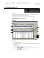
1.1.2 User registration and login certification
A safety PLC performs login certification when opening a project for the purpose of
preventing unauthorized users from illegally accessing.
(1) User registration
A system manager has to define the person in charge, and then register the
user information required for login certification with the project.
The following information is required in user registration.
1) User name
2) Access level (
Section 1.1.1)
3) Password (Omissible if access level is set to "Users".)
Maximum 128 users can be registered with each project, and the operation
authority for each user is determined by the user’s access level.
For example, the user whose access level is Users is not authorized to rewrite a
safety PLC program.
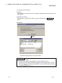
(2) Login certification
When opening a project, a user name and password are required.
After inputting them, login certification is performed based on the set user
registration information.
The available operations determined by the user’s access level can be
performed after login.
Login
certification
Project data
for a safety PLC
GX Developer
Note that login certification is performed to the operation such as "Delete
Section 5.1.3)
project". (
POINT
• The users unregistered with a project cannot open the project.
• The users registered with a project can only perform the operations enabled in the
given access level. (
Section 1.2.2)
1-3
1-3
1 GENERAL DESCRIPTION
MELSOFT
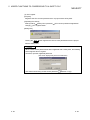
1.1.3 CPU access password
A safety CPU performs access certification by using a password to prevent the
misconnected GX Developer from illegally operating.
The password is referred to a CPU access password.
The CPU access password has to be set to both the GX Developer project and
safety CPU.
When performing the operation that changes control (e.g. program change) from the
GX Developer, the CPU access password of the GX Developer project is compared
with that of the safety CPU.
Only when they are identical, the operation will be allowed.
CPU access password "ABC123"
Can operate, as the CPU access
passwords are identical.
Cannot operate, as the CPU access
passwords are not identical.
GX Developer
GX Developer
CPU access
password
"ABC123"
CPU access
password
"DEF123"
Project A
Project B
POINT
Set different CPU access passwords for each safety CPU.
1-4
1-4
1 GENERAL DESCRIPTION
MELSOFT
1.1.4 Safety CPU operation mode (Safety mode and test mode)
A safety CPU operation mode includes a safety mode and test mode.
The safety CPU operation mode can be switched from the GX Developer.
(1) Safety mode
The safety mode is used when operating a safety system.
In this mode, the operations may lead a safety PLC to a control change (e.g.
Write to PLC, Device test) are inhibited so that the running system is protected.
(2) Test mode
The test mode is used when starting or maintaining a system.
In this mode, all operations including "Write to PLC" and "Device test" are
available. (The available functions depend on the login user’s access level.)
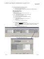
1.1.5 Operation lock
An operation lock inhibits other users from operating the open project. The operation
lock has the following two methods.
Method
Automatic operation
lock
Manual operation
lock
Contents
Automatically locks operation if the GX Developer has not been
operated for a certain period of time.
Manually locks operation.
The following Operation lock screen appears at operation lock.
The user during login or user whose access level is Administrators can unlock the
setting.
(Operation lock screen)
1-5
1-5
1 GENERAL DESCRIPTION
MELSOFT
1.2 Functions Lists
1.2.1 Functions lists
The GX Developer functions are listed below.
(1) Common functions list
The following shows the fixed functions independent of the editing and the type
of setting target.
Project (Common function)
Only for
monitoring
1
New project
Open project
Close project
Save
Save as
Creates a new project.
Opens the existing project.
Closes an open project.
Saves a project.
Names and saves a project.
Delete project
Deletes the existing project.
Verify
Copy
Change PLC type
Import file
Import from GPPQ format file
Import from GPPA format file
Import from FXGP(WIN) format file
Import from FXGP(DOS) format file
Import from Melsec Medoc format file
(Print out)
Import from TEXT, CSV format file…
Export file
Export to GPPQ format file
Export to GPPA format file
Verifies data between projects.
Copies data between projects.
Changes a PLC type.
Export to FXGP(WIN) format file
Export to FXGP(DOS) format file
Export to TEXT, CSV format file…
---
QSCPU
2
---
Reads a GPPQ file.
Reads a GPPA file.
Reads a FXGP(WIN) format file.
Reads a FXGP(DOS) format file.
Reads a Melsec Medoc printing format
file.
Reads a text and CSV file.
3
5.1.1
5.1.3
1.2.2
1.2.2
3
3
5.1.3
5.1.3
5.1.3
Appendix 1
-------------
--Writes data to a GPPQ file.
Writes data to a GPPA file.
Writes data to a FXGP(WIN) format
file.
Writes data to a FXGP(DOS) format
file.
Writes data to a text and CSV file.
Reference
---
---------------
(To the next page)
1: Indicates the availability when the GX Developer is installed as "Only for monitoring
GX Developer".
: Available, : Unavailable
2: Indicates the menu selectability when using the QSCPU.
: Selectable (Only for the QSCPU),
: Selectable (Some changes for the QSCPU in the function common to all models),
: Selectable (No changes for the QSCPU in the function common to all models),
: Cannot be selected.
3: For functions without references, refer to the GX Developer Version 8 Operating
Manual.
1-6
1-6
1 GENERAL DESCRIPTION
MELSOFT
(Continued from the previous page.)
Project (Common function)
Only for
monitoring
1
Macro
Registration macros
Macro utilize
Delete macros
Macro reference path
Security operation
User management
Wait time settings
Operation lock
Printer setup
Print
Start new GX Developer session
Exit GX Developer
---
3
---
-----------
---
---
--5.1.2
5.1.4
5.1.4
--Appendix 1
-----
Only for
monitoring
QSCPU
Reference
Registers/deletes/changes a login user.
Sets the wait time to an operation lock.
Manually locks operation.
Changes printer settings.
Prints data.
Starts a new GX Developer session.
Exits the GX Developer.
1
2
Displays or hides the toolbar.
Displays or hides the status bar.
Displays or hides the project data list.
--Does not sort the project data list.
Sorts the project data list in ascending order.
Sorts the project data list in descending order.
Displays the Elapsed time dialog box.
Reference
2
Registers macros.
Utilizes macros.
Deletes a macro file.
Changes the macro instruction reference
path.
View
Toolbar
Status bar
Project data list
Project data display format
Not sort
Sort data name ascending
Sort data name descending
Elapsed time
QSCPU
---
3
-----------------
(To the next page)
1: Indicates the availability when the GX Developer is installed as "Only for monitoring
GX Developer".
: Available, : Unavailable
2: Indicates the menu selectability when using the QSCPU.
: Selectable (Only for the QSCPU),
: Selectable (Some changes for the QSCPU in the function common to all models),
: Selectable (No changes for the QSCPU in the function common to all models),
: Cannot be selected.
3: For functions without references, refer to the GX Developer Version 8 Operating
Manual.
1-7
1-7
1 GENERAL DESCRIPTION
MELSOFT
(Continued from the previous page.)
Online (Common function)
Only for
monitoring
1
Transfer setup
Read from PLC
Write to PLC
Verify with PLC
Write to PLC (Flash ROM)
Write the program memory to
ROM
Write to PLC (Flash ROM)
Delete PLC data
Change PLC data attributes
PLC user data
Read PLC user data
Write PLC user data
Delete PLC user data
Monitor
Monitor mode
Monitor (Write mode)
Start monitor (All windows)
Stop monitor (All windows)
Local device monitor
Device batch
Entry data monitor
Buffer memory batch
Program monitor list
Interrupt program monitor list
Debug (ladder)
Device test
Forced input output
registration/cancellation
Trace
Remote operation
Redundant operation
QSCPU
Reference
2
3
Specifies a PLC CPU destination from the GX
Developer.
Reads data from a PLC CPU.
Writes data to a PLC CPU.
Verifies data with PLC CPU data.
---
---
---
Writes program memory data to standard
ROM/IC memory card (ROM).
Writes data to standard ROM/IC memory card
(ROM).
Deletes the data in a PLC CPU.
Changes PLC CPU data attributes.
5.7
---
---
---
---
---
Reads user data from a PLC CPU.
Writes user data to a PLC CPU.
Deletes the user data in a PLC CPU.
Places the ladder editing screen in the
monitor mode.
Sets the ladder (Monitor write) mode.
Starts monitoring all open windows.
Stops monitoring all open windows.
Switches the execute/non-execute of the local
device monitor.
Monitors devices in the batch mode.
Monitors devices in one screen.
Monitors buffer memory in the batch mode.
Monitors a program list.
Lists interrupt programs.
------------Appendix 1
-----------
--Turns on/off the device or changes the value.
Registers/cancels the forced I/O of input
relays (X)/output relays (Y).
Performs sampling trace.
Remotely operates a PLC CPU.
Performs redundant operation.
---------
---
------------Appendix 1
----Appendix 1
---
(To the next page)
1: Indicates the availability when the GX Developer is installed as "Only for monitoring
GX Developer".
: Available, : Unavailable
2: Indicates the menu selectability when using the QSCPU.
: Selectable (Only for the QSCPU),
: Selectable (Some changes for the QSCPU in the function common to all models),
: Selectable (No changes for the QSCPU in the function common to all models),
: Cannot be selected.
3: For functions without references, refer to the GX Developer Version 8 Operating
Manual.
1-8
1-8
1 GENERAL DESCRIPTION
MELSOFT
(Continued from the previous page.)
Online (Common function)
Only for
monitoring
1
Safety CPU operation
Switch safety CPU operation
mode
---
CPU access password
registration/change
PLC memory initialization
Monitor destination select option
Keyword/Password
Register keyword
Delete keyword
Disable keyword
Clear PLC memory
Format PLC memory
Arrange PLC memory
Set clock
5.2.2
5.2.3
---
Diagnoses a PLC CPU.
MELSECNET(II)/10/H diagnostics
Ethernet diagnostics
CC-Link / CC-Link/LT diagnostics
System monitor
Online module change
Diagnoses the network.
Diagnoses the Ethernet.
Diagnoses the CC-Link or CC-Link/LT.
Monitors the system status of a PLC CPU.
Changes a module during online.
Tools (Common function)
---
------Only for
monitoring
QSCPU
2
Reference
3
5.6
Appendix 1
Appendix 1
--Appendix 1
----Only for
monitoring
QSCPU
2
Calculates the file size to be written to a
PLC CPU.
Merges data.
Checks parameters.
Reference
3
---
--Reads data from ROM.
Writes data to ROM.
Compares the data in a PC with the ROM
data.
Writes ROM data to a file.
5.2.4
5.2.5
-----------
1
Write to file
---
Registers/changes a keyword/password.
Cancels the keyword/password.
Temporarily unlocks the keyword/password.
Clears the memory cassette or device
memory in a PLC CPU.
Formats the PLC CPU memory.
Arranges the data area in PLC CPU
memory.
Sets the time of a PLC CPU.
PLC diagnostics
Compare
---
5.2.1
1
Marge data
Check parameter
Transfer ROM
Read
Write
3
Displays the ROM information of a project/
PLC CPU.
Registers/changes a CPU access
password.
Initializes PLC CPU memory.
Switches the CPU to be monitored.
Diagnostics (Common function)
Reference
2
Switches a PLC CPU mode.
ROM information
Confirm project memory size
QSCPU
---
Appendix 1
-------------
(To the next page)
1: Indicates the availability when the GX Developer is installed as "Only for monitoring
GX Developer".
: Available, : Unavailable
2: Indicates the menu selectability when using the QSCPU.
: Selectable (Only for the QSCPU),
: Selectable (Some changes for the QSCPU in the function common to all models),
: Selectable (No changes for the QSCPU in the function common to all models),
: Cannot be selected.
3: For functions without references, refer to the GX Developer Version 8 Operating
Manual.
1-9
1-9
1 GENERAL DESCRIPTION
MELSOFT
(Continued from the previous page.)
Tools (Common function)
Only for
monitoring
1
Clear all parameters
IC memory card
Read IC memory card
Write IC memory card
Read image data…
Write image data…
Start ladder logic test
Set TEL data
Connection
Disconnect
---
---
---
---
Connects the line for the A6TEL/Q6TEL.
Disconnects the line.
Sets the notice destination data of the A6TEL
or Q6TEL.
Registers the modem.
Sets phone numbers.
AT command
Call book
Intelligent function utility
Customize keys
Options
Create start-up settings file
Appendix 1
--Only for
monitoring
Key operation list
Product information
Connect to MELFANSweb
QSCPU
2
Reference
3
----------Only for
monitoring
1
Displays the description of each CPU error
code.
Displays the description of special relays or
special registers.
Displays the description of each key operation.
Displays product information such as a version
number.
Connects to the MELFANSweb.
-------
---
Overlaps windows.
Vertically arranges windows.
Horizontally arranges windows.
Arranges icons at the bottom of the window.
Closes all open windows.
Help (Common function)
---------------------
---
1
Special relay/register
---
Shows the utility names required to edit the
intelligent function unit parameters.
Changes the key assignment for ladder symbol
input.
Sets the options.
Creates a file to save the initial settings of a
project.
Window (Common function)
3
---
---
Utility list
Reference
---
Reads data from an IC memory card.
Writes data to an IC memory card.
Reads image data.
Writes image data.
Starts/stops the ladder logic test.
TEL data
CPU error
2
Deletes the unused device comments in a
program.
Deletes parameters.
Delete unused comments
Cascade
Tile vertically
Tile horizontally
Arrange icons
Close all Windows
QSCPU
QSCPU
2
Reference
3
-----------
1: Indicates the availability when the GX Developer is installed as "Only for monitoring
GX Developer".
: Available, : Unavailable
2: Indicates the menu selectability when using the QSCPU.
: Selectable (Only for the QSCPU),
: Selectable (Some changes for the QSCPU in the function common to all models),
: Selectable (No changes for the QSCPU in the function common to all models),
: Cannot be selected.
3: For functions without references, refer to the GX Developer Version 8 Operating
Manual.
1 - 10
1 - 10
1 GENERAL DESCRIPTION
MELSOFT
(2) Ladder editing functions list
The following functions can be performed to edit ladders, operation outputs, and
transition conditions.
When installing the GX Developer with its functions limited, the ladder symbols
can be used for searching.
Project
Only for
monitoring
Edit data
New
Copy
Delete
Rename
Change program type
Function Block
Diversion
Rename
FB change module address
---
---
---
---
-------------------
Diverts the FB to a ladder program.
Renames the diverted FB.
Sets the module start I/O No. used in FB
definition.
--Only for
monitoring
1
Restore after ladder conversion
Cut
Copy
Paste
Insert line
Delete line
Insert row
Delete row
Insert NOP batch
Delete NOP batch
Draw line
Delete line
Change TC setting
Read mode
Write mode
Reverses the last operation.
Restores a program to the status after ladder
conversion.
Moves the selected data to the clipboard.
Copies the selected data to the clipboard.
Pastes the clipboard contents at the cursor
position.
Inserts a row at the cursor position.
Deletes a row at the cursor position.
Inserts a column at the cursor position.
Deletes a column at the cursor position.
Inserts NOP before the ladder block at the
cursor position.
Deletes all the NOPs in a program at a time.
Inserts a line.
Deletes a line.
Changes the setting value of the
timer/counter.
Places a ladder screen in the read mode.
Places a ladder screen in the write mode.
Reference
3
Adds data to a project.
Copies the data in a project.
Deletes the data in a project.
Renames the data in a project.
Changes a ladder and SFC with each other.
Edit
Undo
QSCPU
2
1
QSCPU
2
Reference
3
------Appendix 1
Appendix 1
----------------Appendix 1
----(To the next page)
1: Indicates the availability when the GX Developer is installed as "Only for monitoring
GX Developer".
: Available, : Unavailable
2: Indicates the menu selectability when using the QSCPU.
: Selectable (Only for the QSCPU),
: Selectable (Some changes for the QSCPU in the function common to all models),
: Selectable (No changes for the QSCPU in the function common to all models),
: Cannot be selected.
3: For functions without references, refer to the GX Developer Version 8 Operating
Manual.
1 - 11
1 - 11
1 GENERAL DESCRIPTION
MELSOFT
(Continued from the previous page.)
Only for
monitoring
Edit
1
Ladder symbol
---
QSCPU
Reference
2
3
---
---
Open contact
Inserts
at the cursor position.
---
Close project contact
Inserts
at the cursor position.
---
Open branch
Inserts
at the cursor position.
---
Close project branch
Inserts
at the cursor position.
---
Coil
Inserts
at the cursor position.
---
Application instruction
Inserts
at the cursor position.
---
Vertical line
Inserts
at the cursor position.
---
Horizontal line
Inserts
at the cursor position.
---
Delete vertical line
Inserts
at the cursor position.
---
Delete Horizontal line
Inserts
at the cursor position.
---
Rising pulse
Inserts
at the cursor position.
---
Falling pulse
Inserts
at the cursor position.
---
Rising pulse Open branch
Inserts
at the cursor position.
---
Falling pulse Close branch
Inserts
at the cursor position.
---
Invert operation results
Inserts
at the cursor position.
---
Inserts
at the cursor position.
---
Inserts
at the cursor position.
---
Convert operation results to
rising pulse
Convert operation results to
falling pulse
Documentation
Comment
Statement
Note
Statement/Note block edit
--Edits the comment at the cursor position.
Edits the statement at the cursor position in
a ladder.
Edits the note at the cursor position in a
ladder.
Edits the statement/note under program at a
time.
---
-----------
(To the next page)
1: Indicates the availability when the GX Developer is installed as "Only for monitoring
GX Developer".
: Available, : Unavailable
2: Indicates the menu selectability when using the QSCPU.
: Selectable (Only for the QSCPU),
: Selectable (Some changes for the QSCPU in the function common to all models),
: Selectable (No changes for the QSCPU in the function common to all models),
: Cannot be selected.
3: For functions without references, refer to the GX Developer Version 8 Operating
Manual.
1 - 12
1 - 12
1 GENERAL DESCRIPTION
MELSOFT
(Continued from the previous page.)
Find/Replace
Only for
monitoring
1
Find device
Find instruction
Find step No.
Find character string
Find contact or coil
Replace device
Device block replacement
Replace instruction
Change open/close contact
Replace character string
Change module start address
Replace statement/note type
Cross reference window
display
Cross reference list
List of used devices
Converts a program.
Converts all the programs (not converted yet)
at a time.
Converts all programs at a time.
Converts a program and writes it to a PLC CPU
during RUN.
Reference
3
------------------------------Only for
monitoring
1
Convert block (Online change)
2
Searches for a device.
Searches for an instruction.
Searches for a step number.
Searches for the character string in a comment,
note, or statement.
Searches for a contact or coil.
Searches for and replaces a device.
Searches for and replaces multiple devices at a
time.
Searches for and replaces an instruction.
Searches for and replaces a contact a with a
contact b.
Searches for and replaces the character string
in a comment, note, or statement.
Searches for and replaces the module start I/O
No. of the buffer memory address instructions.
Searches for and replaces the type of a
note/statement.
Displays where the specified device or label is
used.
Lists the step numbers and usage types of the
specified device.
Finds where the device is used.
Convert
Convert
Convert (All programs being
edited)
Convert block (All programs)
QSCPU
QSCPU
2
Reference
3
------Appendix 1
(To the next page)
1: Indicates the availability when the GX Developer is installed as "Only for monitoring
GX Developer".
: Available, : Unavailable
2: Indicates the menu selectability when using the QSCPU.
: Selectable (Only for the QSCPU),
: Selectable (Some changes for the QSCPU in the function common to all models),
: Selectable (No changes for the QSCPU in the function common to all models),
: Cannot be selected.
3: For functions without references, refer to the GX Developer Version 8 Operating
Manual.
1 - 13
1 - 13
1 GENERAL DESCRIPTION
MELSOFT
(Continued from the previous page.)
Only for
monitoring
View
1
Comment
Statement
Note
Alias
Display device program
Macro instruction format display
Display current monitored values
Comment format
4 8 characters,
2 8 characters
3 5 characters
Alias format display
Displayed instead of device
Displayed with device
Right
Number of comment lines
Zoom
Instruction list/Ladder
Set the contact
9 contacts
11 contacts
Elapsed time
Display step synchronization
2
8 or 2
-----
8
-----
5characters.
---
---
Displays the machine name at the device
name display position.
Arranges and displays the machine name
above the device name.
---------
---
---
Vertically splits the screen in two in the
zoom/device display.
Horizontally splits the screen in two in the
zoom/device display.
Displays device comments in the specified
number of rows (1 to 4 rows).
Displays a ladder in the specified
magnification.
Switches between the ladder mode and list
mode.
-------------
--Displays a ladder in 9 contacts.
Displays a ladder in 11 contacts.
Displays the Elapsed time dialog box.
Synchronizes the steps of label display with
those of device display.
3
---
--Displays comments in 4
characters.
Displays comments in 3
Reference
-----------
Displays or hides comments.
Displays or hides statements.
Displays or hides notes.
Displays or hides device names.
Displays or hides the device display screen.
Displays the instructions in the user macro
instruction format.
Displays or hides the current monitored
values.
Device program display mode
Below
QSCPU
---
-----------
(To the next page)
1: Indicates the availability when the GX Developer is installed as "Only for monitoring
GX Developer".
: Available, : Unavailable
2: Indicates the menu selectability when using the QSCPU.
: Selectable (Only for the QSCPU),
: Selectable (Some changes for the QSCPU in the function common to all models),
: Selectable (No changes for the QSCPU in the function common to all models),
: Cannot be selected.
3: For functions without references, refer to the GX Developer Version 8 Operating
Manual.
1 - 14
1 - 14
1 GENERAL DESCRIPTION
MELSOFT
(Continued from the previous page.)
Online
Only for
monitoring
1
Monitor
Monitor mode
Monitor (Write mode)
Start monitor
Stop monitor
Change current value monitor
(Decimal)
Change current value monitor
(Hexadecimal)
Monitor condition setup
Monitor stop condition setup
Scan time measurement
Entry ladder monitor
Delete all entry ladder
Debug
Debug
Skip execution
Partial execution
Step execution
---
Reference
2
3
---
---
Places the ladder editing screen in the
monitor mode.
Sets the ladder (Monitor write) mode.
Restarts monitoring.
Stops monitoring.
Displays the current device values of a
ladder monitor in decimal form.
Displays the current device values of a
ladder monitor in hexadecimal form.
Sets monitor execution conditions.
Sets monitor stop conditions.
Measures scan time.
Registers ladder blocks.
Deletes all the registered ladder blocks.
-------------
---
---
Only for
monitoring
QSCPU
---------------------
Performs/disables the debugging function.
Makes settings for skip.
Makes settings for partial execution.
Makes settings for step execution.
Tools
1
Check program
Change display color
QSCPU
Checks a program.
Changes a display color.
Reference
2
3
--5.4
1: Indicates the availability when the GX Developer is installed as "Only for monitoring
GX Developer".
: Available, : Unavailable
2: Indicates the menu selectability when using the QSCPU.
: Selectable (Only for the QSCPU),
: Selectable (Some changes for the QSCPU in the function common to all models),
: Selectable (No changes for the QSCPU in the function common to all models),
: Cannot be selected.
3: For functions without references, refer to the GX Developer Version 8 Operating
Manual.
1 - 15
1 - 15
1 GENERAL DESCRIPTION
MELSOFT
(3) Label program editing functions list
The following functions can be performed to edit a label program.
Project
Only for
monitoring
Edit data
New
Copy
Delete
Rename
Change program type
Function Block
Diversion
Rename
FB change module address
---
---
---
---
-------------------
Diverts the FB to a ladder program.
Renames the diverted FB.
Sets the module start I/O No. used in FB
definition.
--Only for
monitoring
1
Paste
Insert line
Add line
Delete line
Delete Auto External (Au)
Delete all
Auto device setting
Global variable setting
Import the device comment
Export the device comment
Find character string
Replace device
Replace character string
2
Searches for the device in the label variable
setting screen.
Searches for the character string in the label
variable setting screen.
Searches for and replaces the device in the
label variable setting screen.
Searches for and replaces the character
string in the label variable setting screen.
Reference
3
--------------------------Only for
monitoring
1
Find device
QSCPU
Reverses the last operation.
Moves the selected data to the clipboard.
Copies the selected data to the clipboard.
Pastes the clipboard contents at the cursor
position.
Inserts a row at the cursor position.
Adds a row under the cursor position.
Deletes a row at the cursor position.
Deletes all Auto External.
Deletes all variables.
Sets the ranges for the devices to be
automatically assigned.
Opens the global variable setting screen.
Imports device comments (Local label
variables only).
Exports label comments.
Find/Replace
Reference
3
Adds data to a project.
Copies the data in a project.
Deletes the data in a project.
Renames the data in a project.
Changes a ladder and SFC with each other.
Edit
Undo
Cut
Copy
QSCPU
2
1
QSCPU
2
Reference
3
--------(To the next page)
1: Indicates the availability when the GX Developer is installed as "Only for monitoring
GX Developer".
: Available, : Unavailable
2: Indicates the menu selectability when using the QSCPU.
: Selectable (Only for the QSCPU),
: Selectable (Some changes for the QSCPU in the function common to all models),
: Selectable (No changes for the QSCPU in the function common to all models),
: Cannot be selected.
3: For functions without references, refer to the GX Developer Version 8 Operating
Manual.
1 - 16
1 - 16
1 GENERAL DESCRIPTION
MELSOFT
(Continued from the previous page.)
Convert (Function for local label variable/global label variable editing)
Only for
monitoring
1
Convert/Compile
Convert/Compile (All programs
being edited)
Convert/Compile (All programs)
Start monitor
Stop monitor
Change current value monitor
(Decimal)
Change current value monitor
(Hexadecimal)
Monitor condition setup
Monitor stop condition setup
Scan time measurement
Entry ladder monitor
Delete all entry ladder
Debug
Debug
Skip execution
Partial execution
Step execution
--Only for
monitoring
---
QSCPU
3
---
-----
---------
---
---
Only for
monitoring
QSCPU
Performs/disables the debugging function.
Makes settings for skip.
Makes settings for partial execution.
Makes settings for step execution.
2
Checks a program.
--Sorts by label.
Sorts by device/constant.
Sorts by device type.
Changes a display color.
Reference
2
---
1
Check program
Sort
Label order
Device/Constant order
Device type order
Change display color
3
---
Sets the monitor mode.
Sets the write mode during ladder
monitoring.
Starts monitoring.
Stops monitoring.
Displays the current device values of a
ladder monitor in decimal form.
Displays the current device values of a
ladder monitor in hexadecimal form.
Sets monitor execution conditions.
Sets monitor stop conditions.
Measures scan time.
Registers ladder blocks.
Deletes all the registered ladder blocks.
Tools
Reference
---
1
Monitor (Write mode)
2
Compiles a label program.
Compiles all the label programs (not
compiled yet).
Compiles all label programs.
Online
Monitor
Monitor mode
QSCPU
---
--------------------Reference
3
-------------
1: Indicates the availability when the GX Developer is installed as "Only for monitoring
GX Developer".
: Available, : Unavailable
2: Indicates the menu selectability when using the QSCPU.
: Selectable (Only for the QSCPU),
: Selectable (Some changes for the QSCPU in the function common to all models),
: Selectable (No changes for the QSCPU in the function common to all models),
: Cannot be selected.
3: For functions without references, refer to the GX Developer Version 8 Operating
Manual.
1 - 17
1 - 17
1 GENERAL DESCRIPTION
MELSOFT
(4) Device comment editing functions list
The following functions can be performed to edit device comments.
Project
Only for
monitoring
Edit data
New
Copy
Delete
Rename
Change program type
Function Block
Diversion
Rename
FB change module address
---
---
---
---
-------------------
Diverts the FB to a ladder program.
Renames the diverted FB.
Sets the module start I/O No. used in FB
definition.
--Only for
monitoring
1
Paste
Clear all (all devices)
Clear all (displayed devices)
Setup comment
Setup comment range
Replace character string
3
--------Only for
monitoring
QSCPU
2
Reference
3
----Only for
monitoring
1
Converts/compiles all programs at a time.
Reference
---
Searches for the character string in the
device comment screen.
Searches for and replaces the character
string in the device comment screen.
Convert
Convert (All programs being
edited)
2
-----
1
Find character string
QSCPU
Moves the selected data to the clipboard.
Copies the selected data to the clipboard.
Pastes the clipboard contents at the cursor
position.
Deletes the comments or device names of
all devices.
Deletes the displayed device comments or
device names.
Sets a comment type to common
comments/comments by program.
Sets comment ranges.
Find/Replace
Reference
3
Adds data to a project.
Copies the data in a project.
Deletes the data in a project.
Renames the data in a project.
Changes a ladder and SFC with each other.
Edit
Cut
Copy
QSCPU
2
1
QSCPU
2
Reference
3
--(To the next page)
1: Indicates the availability when the GX Developer is installed as "Only for monitoring
GX Developer".
: Available, : Unavailable
2: Indicates the menu selectability when using the QSCPU.
: Selectable (Only for the QSCPU),
: Selectable (Some changes for the QSCPU in the function common to all models),
: Selectable (No changes for the QSCPU in the function common to all models),
: Cannot be selected.
3: For functions without references, refer to the GX Developer Version 8 Operating
Manual.
1 - 18
1 - 18
1 GENERAL DESCRIPTION
MELSOFT
(Continued from the previous page.)
Online
Only for
monitoring
1
Monitor
Monitor mode
Monitor (Write mode)
Start monitor
Stop monitor
Change current value monitor
(Decimal)
Change current value monitor
(Hexadecimal)
Monitor condition setup
Monitor stop condition setup
Scan time measurement
Entry ladder monitor
Delete all entry ladder
Debug
Debug
Skip execution
Partial execution
Step execution
---
3
---
---------------
---
---
Only for
monitoring
QSCPU
Performs/disables the debugging function.
Makes settings for skip.
Makes settings for partial execution.
Makes settings for step execution.
1
Checks a program.
Changes a display color.
Reference
2
Sets the monitor mode.
Sets the write mode during ladder monitoring.
Starts monitoring.
Stops monitoring.
Displays the current device values of a ladder
monitor in decimal form.
Displays the current device values of a ladder
monitor in hexadecimal form.
Sets monitor execution conditions.
Sets monitor stop conditions.
Measures scan time.
Registers ladder blocks.
Deletes all the registered ladder blocks.
Tools
Check program
Change display color
QSCPU
2
--------------------Reference
3
-----
1: Indicates the availability when the GX Developer is installed as "Only for monitoring
GX Developer".
: Available, : Unavailable
2: Indicates the menu selectability when using the QSCPU.
: Selectable (Only for the QSCPU),
: Selectable (Some changes for the QSCPU in the function common to all models),
: Selectable (No changes for the QSCPU in the function common to all models),
: Cannot be selected.
3: For functions without references, refer to the GX Developer Version 8 Operating
Manual.
1 - 19
1 - 19
1 GENERAL DESCRIPTION
MELSOFT
(5) Device memory editing functions list
The following functions can be performed to edit device memory.
Project
Only for
monitoring
Edit data
New
Copy
Delete
Rename
Change program type
Function Block
Diversion
Rename
FB change module address
---
---
---
---
-------------------
Diverts the FB to a ladder program.
Renames the diverted FB.
Sets the module start I/O No. used in FB
definition.
--Only for
monitoring
1
Paste
Clear all (all devices)
Clear all (displayed devices)
FILL
Find character string
Replacing data
Replace character string
3
------Only for
monitoring
QSCPU
2
Reference
3
--------Only for
monitoring
1
Converts/compiles all programs at a time.
Reference
---
Searches for the data in the device memory
screen.
Searches for the character string in the
device memory screen.
Searches for and replaces the data in the
device memory screen.
Searches for and replaces the character
string in the device memory screen.
Convert
Convert (All programs being
edited)
2
-----
1
Finding data
QSCPU
Moves the selected data to the clipboard.
Copies the selected data to the clipboard.
Pastes the clipboard contents at the cursor
position.
Deletes all device data.
Deletes the displayed device data.
Sets all data to the specified value.
Find/Replace
Reference
3
Adds data to a project.
Copies the data in a project.
Deletes the data in a project.
Renames the data in a project.
Changes a ladder and SFC with each other.
Edit
Cut
Copy
QSCPU
2
1
QSCPU
2
Reference
3
--(To the next page)
1: Indicates the availability when the GX Developer is installed as "Only for monitoring
GX Developer".
: Available, : Unavailable
2: Indicates the menu selectability when using the QSCPU.
: Selectable (Only for the QSCPU),
: Selectable (Some changes for the QSCPU in the function common to all models),
: Selectable (No changes for the QSCPU in the function common to all models),
: Cannot be selected.
3: For functions without references, refer to the GX Developer Version 8 Operating
Manual.
1 - 20
1 - 20
1 GENERAL DESCRIPTION
MELSOFT
(Continued from the previous page.)
Online
Only for
monitoring
1
Monitor
Monitor mode
Monitor (Write mode)
Start monitor
Stop monitor
Change current value monitor
(Decimal)
Change current value monitor
(Hexadecimal)
Monitor condition setup
Monitor stop condition setup
Scan time measurement
Entry ladder monitor
Delete all entry ladder
Debug
Debug
Skip execution
Partial execution
Step execution
---
3
---
---------------
---
---
Only for
monitoring
QSCPU
Performs/disables the debugging function.
Makes settings for skip.
Makes settings for partial execution.
Makes settings for step execution.
1
Checks a program.
Changes a display color.
Reference
2
Sets the monitor mode.
Sets the write mode during ladder monitoring.
Starts monitoring.
Stops monitoring.
Displays the current device values of a ladder
monitor in decimal form.
Displays the current device values of a ladder
monitor in hexadecimal form.
Sets monitor execution conditions.
Sets monitor stop conditions.
Measures scan time.
Registers ladder blocks.
Deletes all the registered ladder blocks.
Tools
Check program
Change display color
QSCPU
2
--------------------Reference
3
-----
1: Indicates the availability when the GX Developer is installed as "Only for monitoring
GX Developer".
: Available, : Unavailable
2: Indicates the menu selectability when using the QSCPU.
: Selectable (Only for the QSCPU),
: Selectable (Some changes for the QSCPU in the function common to all models),
: Selectable (No changes for the QSCPU in the function common to all models),
: Cannot be selected.
3: For functions without references, refer to the GX Developer Version 8 Operating
Manual.
1 - 21
1 - 21
1 GENERAL DESCRIPTION
MELSOFT
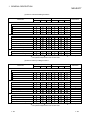
1.2.2 Restricting operations by using safety CPU operation mode/access level
This section explains the operability and restrictions of each GX Developer function
differ depends on the combination of safety CPU operation mode and an access
level.
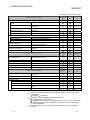
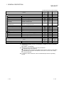
(1) Common functions
Safety Mode
Menu Item
Project
New project
Open project
Close project
Save
Save as
Delete project
Verify
Copy
Security operation
User management
Wait time settings
Operation lock
Printer setup
Print
Start new GX Developer session
Exit GX Developer
View
Toolbar
Status bar
Project data list
Project data display format
Not sort
Sort data name ascending
Sort data name descending
Test Mode
Admin.
Develop.
Users
Admin.
Develop.
Users
---
---
---
---
---
---
Restrictions
----------: Refer to
: Refer to
-------------------------------------
1.
2.
(To the next page)
: Can be operated. : Can be operated with restrictions.
--: Can perform independent of the access level.
: Cannot be operated.
1: When overwriting the existing project, logging in to the project is required.
"Save as" can be performed, when the access level of the login user is
"Administrators" or "Developers".
2: Log in to the project to be deleted is required.
"Delete project" can be performed, when the access level of the login user is
"Administrators" or "Developers".
1 - 22
1 - 22
1 GENERAL DESCRIPTION
MELSOFT
(Continued from the previous page.)
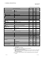
Safety Mode
Menu Item
Admin. Develop.
Test Mode
Users
Admin. Develop.
Restrictions
Users
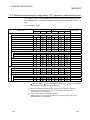
Online
Transfer setup
Read from PLC
Write to PLC
Verify with PLC
Write to PLC (Flash ROM)
Write the program memory to
ROM
Delete PLC data
Monitor
Start monitor (All windows)
Stop monitor (All windows)
Device batch
Entry data monitor
Buffer memory batch
Program monitor list
Debug
Device test
Remote operation
Safety CPU operation
Switch safety CPU operation
mode
ROM information
CPU access password
registration/change
PLC memory initialization
Monitor destination select
option
Clear PLC memory
Format PLC memory
Arrange PLC memory
Set clock
----: Refer to 3.
------------------------Refer to Appendix 1.
Refer to Appendix 1.
------: Refer to
4.
--: Refer to
5.
--------(To the next page)
: Can be operated. : Can be operated with restrictions.
--: Can perform independent of the access level.
: Cannot be operated.
3: "Read from PLC" cannot be newly performed from the safety CPU.
4: Cannot register a CPU access password with a safety CPU.
5: The CPU to be monitored cannot be switched during monitoring.
1 - 23
1 - 23
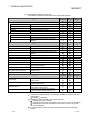
1 GENERAL DESCRIPTION
MELSOFT
(Continued from the previous page.)
Safety Mode
Menu Item
Admin. Develop.
Test Mode
Users
Admin. Develop.
Restrictions
Users
Diagnostics
PLC diagnostics
MELSECNET(II)/10/H diagnostics
CC-Link / CC-Link/LT diagnostics
System monitor
Refer to Appendix 1.
: Refer to 6.
: Refer to 7.
: Refer to 8.
-----
Tools
Marge data
Check parameter
Delete unused comments
Clear all parameters
Customize keys
Options
Create start-up settings file
Window
Cascade
Tile vertically
Tile horizontally
Arrange icons
Close all Windows
Help
CPU error
Special relay/register
Key operation list
Product information
Connect to MELFANSweb
Refer to Appendix 1.
--------Refer to Appendix 1.
--------------------------(To the next page)
: Can be operated. : Can be operated with restrictions.
--: Can perform independent of the access level.
: Cannot be operated.
6: "Clear log" cannot be performed in the PLC Diagnostics screen.
7: "Clear of error history" cannot be performed in the Error history monitor screen of
the MELSECNET(II)/10/H diagnostics.
8: "Loop test" cannot be performed in the CC-Link / CC-Link/LT diagnostics screen.
1 - 24
1 - 24
1 GENERAL DESCRIPTION
MELSOFT
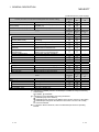
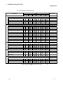
(2) Ladder editing functions
Menu Item
Safety Mode
Admin. Develop.
Test Mode
Users
Admin. Develop.
Users
Restrictions
---------------------------
Project
Edit data
New
Delete
Rename
Function Block
Diversion
Rename
FB change module address
Edit
Undo
Restore after ladder conversion
Cut
Copy
Paste
Insert line
Delete line
Insert row
Delete row
Insert NOP batch
Delete NOP batch
Draw line
Delete line
Change TC setting
Read mode
Write mode
Ladder symbol
Documentation
Refer to Appendix 1.
Refer to Appendix 1.
----------------Refer to Appendix 1.
--------(To the next page)
: Can be operated. : Can be operated with restrictions.
--: Can perform independent of the access level.
1 - 25
: Cannot be operated.
1 - 25
1 GENERAL DESCRIPTION
MELSOFT
(Continued from the previous page.)
Safety Mode
Menu Item
Admin.
Develop.
Test Mode
Users
Admin.
Develop.
Users
Find/Replace
Find device
Find instruction
Find step No.
Find character string
Find contact or coil
Replace device
Device block replacement
Replace instruction
Change open/close contact
Replace character string
Change module start address
Replace statement/note type
Cross reference window display
Cross reference list
List of used devices
Convert
Convert
Convert (All programs being
edited)
Convert block (All programs)
Convert block (Online change)
View
Comment
Statement
Note
Alias
Display device program
Display current monitored values
Comment format
Alias format display
Device program display mode
Number of comment lines
Zoom
Set the contact
Display step synchronization
Restrictions
----------------------------------------------------------------------(To the next page)
: Can be operated. : Can be operated with restrictions.
--: Can perform independent of the access level.
1 - 26
: Cannot be operated.
1 - 26
1 GENERAL DESCRIPTION
MELSOFT
(Continued from the previous page.)
Safety Mode
Menu Item
Admin.
Develop.
Test Mode
Users
Admin.
Develop.
Users
Online
Monitor
Monitor mode
Monitor (Write mode)
Start monitor
Stop monitor
Change current value monitor
(Decimal)
Change current value monitor
(Hexadecimal)
Entry ladder monitor
Delete all entry ladder
Tools
Check program
Change display color
: Can be operated. : Can be operated with restrictions.
--: Can perform independent of the access level.
1 - 27
Restrictions
---------------------------
: Cannot be operated.
1 - 27
1 GENERAL DESCRIPTION
MELSOFT
(3) Label program editing functions
Menu Item
Safety Mode
Admin.
Develop.
Test Mode
Users
Admin.
Develop.
Users
-------------
Project
Edit data
New
Copy
Delete
Rename
Edit
Undo
Cut
Copy
Paste
Insert line
Add line
Delete line
Delete Auto External (Au)
Delete all
Auto device setting
Global variable setting
Import the device comment
Export the device comment
Find/Replace
Find device
Find character string
Replace device
Replace character string
Convert
Convert/Compile
Convert/Compile (All programs
being edited)
Convert/Compile (All programs)
Tools
Sort
Label order
Device/Constant order
Device type order
------------------------------------------------------: Can be operated. : Can be operated with restrictions.
--: Can perform independent of the access level.
1 - 28
Restrictions
: Cannot be operated.
1 - 28
1 GENERAL DESCRIPTION
MELSOFT
(4) Device comment editing functions
Safety Mode
Menu Item
Admin.
Develop.
Test Mode
Users
Admin.
Develop.
Users
Restrictions
-----------------------------------
Project
Edit data
New
Copy
Delete
Rename
Edit
Cut
Copy
Paste
Clear all (all devices)
Clear all (displayed devices)
Setup comment
Setup comment range
Find/Replace
Find character string
Replace character string
: Can be operated. : Can be operated with restrictions.
--: Can perform independent of the access level.
: Cannot be operated.
(5) Device memory editing functions
Menu Item
Safety Mode
Admin.
Develop.
Test Mode
Users
Admin.
Develop.
Users
-------------------------------------
Project
Edit data
New
Copy
Delete
Rename
Edit
Cut
Copy
Paste
Clear all (all devices)
Clear all (displayed devices)
FILL
Find/Replace
Finding data
Find character string
Replacing data
Replace character string
: Can be operated. : Can be operated with restrictions.
--: Can perform independent of the access level.
1 - 29
Restriction
: Cannot be operated.
1 - 29
1 GENERAL DESCRIPTION
MELSOFT
MEMO
1 - 30
1 - 30
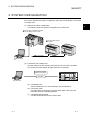
2 SYSTEM CONFIGURATION
MELSOFT
2. SYSTEM CONFIGURATION
This section explains the system configuration when the GX Developer is connected
to a safety CPU.
(1) Safety PLC system configuration
The following shows the system configuration for a safety PLC.
2
Power supply module/CPU module/
CC-Link Safety master module
CC-Link Safety remote
I/O station
CC-Link Safety
GX Developer
(2) Connection with a safety CPU
Only the USB connection, directly connecting a PLC with a PC, is possible.
The access from other station through network is not possible.
PLC direct coupled
(USB communication)
USB cable
GX Developer
Safety PLC
(a) Compatible CPU
Only the QS001CPU can be connected to the GX Developer.
(b) Connection cable
For USB cables connecting a PC with a safety CPU, refer to the GX
Developer Version 8 Operating Manual.
(c) Compatible GX Developer
Use the GX Developer Version 8.40S or later.
2-1
2-1
2 SYSTEM CONFIGURATION
MELSOFT
MEMO
2
2-2
2-2
3 COMMON OPERATIONS
MELSOFT
3 RESTRICTIONS AND PRECAUTIONS
3.1 Precautions for the GX Developer Version Earlier than the Safety CPU
Compatible Version
(1) Precautions for saving and deleting a project
When using the GX Developer whose version is earlier than the safety CPU
compatible version (Version 8.39R or earlier), the login certification to a safety
project cannot be performed to the following operations.
Therefore, take care not to lose a safety project due to malfunctions.
[Relevant Operation]
• Overwriting a safety project and then saving it by using "Save as".
• Deleting a safety project by using "Delete project".
(2) Precautions for opening a project
When using the GX Developer whose version is earlier than the safety CPU
compatible version (Version 8.39R or earlier), the safety project cannot be
opened.
3-1
3-1
3
3 COMMON OPERATIONS
MELSOFT
3.2 Precautions for Management
(1) Precautions for project data management
Be sure to read the Safety Application Guide for correct management/operation
of project data.
A system manager has to back up the project and save the backup data so that
the data restoration is always possible.
(2) Precautions for password management
A system manager has to manage the user information (e.g. user name, login
password, and CPU access password) registered to a project with attention.
3
If losing a login password or CPU access password, either of the following
actions is required.
(a) Losing a login password
The project cannot be opened.
If a system manager has lost the password, re-creating a project is
required.
(b) Losing a CPU access password
When a CPU access password has been set to a safety CPU, "Write to
PLC" cannot be performed unless the same password is set to the project.
Note that the CPU access password that has been set to a safety CPU
cannot be changed.
If losing a CPU access password, initialize the safety CPU by using "PLC
memory initialization" and then rewrite the project to the PLC.
(For "PLC memory initialization"
Section 5.2.4)
(3) Precautions for ROM information management
A system manager has to record and store "ROM information" each time
program memory is written to ROM.
When the ROM information in a safety CPU matches with the previously saved
one, a system manager can judge that the data have not been changed.
(For "ROM information confirmation"
Section 5.2.2)
(Main display contents of ROM information)
• The year/month/day/hour/minute/second when program memory is written to
ROM.
• The parameters and program ID when program memory is written to ROM.
• The user who wrote program memory to ROM.
3-2
3-2
4 PROCEDURES TO OPERATION
MELSOFT
4 PROCEDURES TO OPERATION
This section explains the procedures from creating to operating a project for a safety
PLC (Safety project).
4.1 When Creating a Safety Project
The following shows the procedure from creating to operating the safety project.
Creating the new project
Reference
1) Create a new project.
GX Developer Operating Manual
2) Register the user(s) whose access level is/are Administrators.
5.1.1
3) Create a program and parameters.
GX Developer Operating Manual
4) Register the user(s) who log(s) in to the project.
5.1.2
4
Safety CPU STOP
Reference
Switch the safety CPU to STOP.
----
Safety CPU initial settings
Reference
1) Register a CPU access password for both the project and safety CPU. 1
5.2.3
2) Format the program memory.
GX Developer Operating Manual
1: If the previous CPU access password has been registered
with the safety CPU, initialize the PLC memory in advance.
(
Section 5.2.4)
Writing the parameters and program
1) Write the parameters and program to the PLC.
Reference
GX Developer Operating Manual
2) Reset the safety CPU.
----
Operation check
Switch the safety CPU to RUN and check the operation.
Reference
GX Developer Operating Manual
Switching to the safety mode
Reference
1) Switch the safety CPU to STOP.
----
2) Write the program memory to the ROM.
5.7
3) Switch the safety CPU operation mode to the safety mode.
5.2.1
4) Reset the safety CPU.
----
Switching the safety CPU to RUN
Switch the safety CPU to RUN and confirm the RUN LED turns ON.
Reference
----
Operation
4-1
4-1
4 PROCEDURES TO OPERATION
MELSOFT
4.2 When Modifying the Safety Project in Operation
The following shows the procedure from modifying the safety project in operation to
operating the project.
Open project
Open the operating project.
Reference
5.1.3
Changing the parameters and program
Change the parameters and program.
Reference
GX Developer Operating Manual
Switching to the test mode
4
Switch the safety CPU operation mode to the test mode.
Reference
5.2.1
Writing the parameters and program
Reference
1) Switch the safety CPU to STOP.
2) Write the parameters and program to the PLC.
---GX Developer Operating Manual
3) Reset the safety CPU.
----
Operation check
Switch the safety CPU to RUN and check the operation.
Reference
GX Developer Operating Manual
Switching to the safety mode
Reference
1) Switch the safety CPU to STOP.
----
2) Write the program memory to the ROM.
5.7
3) Switch the safety CPU operation mode to the safety mode.
5.2.1
4) Reset the safety CPU.
----
Switching the safety CPU to RUN
Switch the safety CPU to RUN and confirm the RUN LED turns ON.
Reference
----
Operation
4-2
4-2
5 ADDED FUNCTIONS TO CORRESPOND TO A SAFETY PLC
MELSOFT
5 ADDED FUNCTIONS TO CORRESPOND TO A SAFETY
PLC
5.1 Security Operations
5.1.1 Registering the user when creating a new project
A system manager has to create a new project for a safety PLC.
When creating a new project, the following screen appears.
A system manager has to register the login user whose access level is
Administrators.
1)
2)
5
3)
5)
4)
6)
7)
[Description]
1) User name
Input a user name within 20 characters with the alphabets, numbers, and
symbols corresponding to ASCII code (
Appendix 3) 20H to 7EH.
(For alphabets, an upper-case character is differentiated from a lower-case
character.)
2) Access level
"Administrators" has been set to the access level (Fixed).
3) New password
Input a CPU access password within 6 to 14 characters with the alphabets,
numbers, and symbols corresponding to ASCII code (
Appendix 3) 20H to
7EH.
(For alphabets, an upper-case character is differentiated from a lower-case
character.)
4) Confirm new password
Input the same password with 3) for confirmation.
5) Access level explanation field
Displays the explanation for Administrators.
5-1
5-1
5 ADDED FUNCTIONS TO CORRESPOND TO A SAFETY PLC
6)
MELSOFT
OK button
Closes the screen when the setting is correct.
The login to the project is performed with the registered user.
In addition, the new user is registered with the User management screen
described in Section 5.1.2.
7)
Cancel button
Cancels the setting and returns to the New Project screen.
POINT
For the additional registration of login users, refer to Section 5.1.2.
5
5-2
5-2
5 ADDED FUNCTIONS TO CORRESPOND TO A SAFETY PLC
MELSOFT
5.1.2 Registering/deleting/changing a login user
Admin.
Develop.
Users
SAFETY
TEST
[Purpose]
Registers/deletes/changes the login user of the project for a safety PLC.
[Operating Procedure]
Select [Project] [Security operation]
[User management].
[Dialog Box]
2)
1)
3)
5)
4)
6)
7)
8)
9)
5-3
10)
5-3
5 ADDED FUNCTIONS TO CORRESPOND TO A SAFETY PLC
MELSOFT
[Description]
1) User list/selection field
• Display/Selection
Displays the user names with their access levels registered with the project.
Select the registered user to be deleted or the user whose information is to
be changed.
• Search
Inputting the first character of a user name finds the user name(s) having
the same first character.
• Sort
Clicking the title (User name or access level) by using a mouse sorts the
list based on the title.
The list is alternatively sorted between ascending order and descending
order.
2) Number of user registration
Displays the number of the users registered to the project (Max. 128).
3)
Add button
Displays the Add new user screen. (
4)
(1) in this section)
Delete button
Deletes the selected user.
5)
Change button
Displays the User change screen. (
6)
(2) in this section)
User copy button
Copies (Adds or overwrites) the user information registered with other project to
the open project.
(For operating procedure
(4) in this section)
7) Password for ******
Displays the user name selected in the list of 1).
8)
Password settings button
Displays the Password settings screen. (
9)
(3) in this section)
OK button
Registers the set user information, and closes the screen.
10) Cancel button
Cancels the set user information, and closes the screen.
5-4
5-4
5 ADDED FUNCTIONS TO CORRESPOND TO A SAFETY PLC
MELSOFT
(1) Adding a new user
[Purpose]
Adds the user who can log in to the project under editing.
[Operating Procedure]
Select [Project]
[Security operation]
[User management]
Add button.
[Dialog Box]
1)
2)
3)
5)
4)
6)
7)
[Description]
1) User name
Input a user name within 20 characters with the alphabets, numbers, and
symbols corresponding to ASCII code (
Appendix 3) 20H to 7EH.
(For alphabets, an upper-case character is differentiated from a lower-case
character.)
2) Access level
Select an access level for the new user from the combo box.
3) New password
Input a CPU access password within 6 to 14 characters with the alphabets,
numbers, and symbols corresponding to ASCII code (
Appendix 3) 20H to
7EH.
(For alphabets, an upper-case character is differentiated from a lower-case
character.)
When the access level is set to "Users", the password input can be skipped.
4) Confirm new password
Input the same password with 3) for confirmation.
5) Access level explanation field
Displays the explanation for the access level selected in 2).
6)
OK button
Closes the screen when the setting is correct.
The new user is registered with the User management screen.
7)
Cancel button
Cancels the setting, and closes the screen.
5-5
5-5
5 ADDED FUNCTIONS TO CORRESPOND TO A SAFETY PLC
MELSOFT
(2) Changing the registered user information
[Purpose]
Changes the registered user information.
[Operating Procedure]
Select [Project]
[Security operation]
[User management]
Change button.
[Dialog Box]
1)
2)
3)
4)
5)
6)
[Description]
1) Title bar
Displays the user whose information is to be changed.
2) User name
Displays the user whose information is to be changed.
To change the user name, input a new user name within 20 characters with the
alphabets, numbers, and symbols corresponding to ASCII code (
Appendix
3) 20H to 7EH.
(For alphabets, an upper-case character is differentiated from a lower-case
character.)
3) Access level
Displays the access level for the user whose information is to be changed.
To change the access level, select the desired level from the combo box.
4) Access level explanation field
Displays the explanation for the access level selected in 3).
5)
OK button
Closes the screen when the setting is correct.
The new user information is registered with the User management screen.
6)
Cancel button
Cancels the setting, and closes the screen.
POINT
• Changing user information
The information on the user (User name and access level) during login cannot be
changed.
• Changing access level
When changing the access level to other than "Users", the "Password settings"
screen appears. Then, set a password in the screen.
When changing the access level to "Users", the password settings can be
skipped.
5-6
5-6
5 ADDED FUNCTIONS TO CORRESPOND TO A SAFETY PLC
MELSOFT
(3) Setting/changing a password
[Purpose]
Sets/changes the registered user password.
[Operating Procedure]
Select [Project] [Security operation]
[User management]
Password settings button.
[Dialog Box]
1)
2)
3)
4)
[Description]
1) New password
Input a CPU access password within 6 to 14 characters with the alphabets,
numbers, and symbols corresponding to ASCII code (
Appendix 3) 20H to
7EH.
(For alphabets, an upper-case character is differentiated from a lower-case
character.)
2) Confirm new password
Input the same password with 1) for confirmation.
3)
OK button
Closes the screen when the setting is correct.
The new password is set.
4)
Cancel button
Cancels the setting, and closes the screen.
5-7
5-7
5 ADDED FUNCTIONS TO CORRESPOND TO A SAFETY PLC
MELSOFT
(4) Copying user information
[Purpose]
Copies (Adds or overwrites) the user information registered with other project to the
open project.
[Operating Procedure]
Select [Project]
[Security operation]
[User management]
User copy
button.
[Dialog Box]
Yes
Select the original project in the screen above.
POINT
Copying user information
• Selecting the original project displays the Login certification screen.
Input the user name and password for logging in to the original project. Only the
users whose access levels are Administrators can log in to the project. (For login
certification
Section 5.1.3)
5-8
5-8
5 ADDED FUNCTIONS TO CORRESPOND TO A SAFETY PLC
MELSOFT
5.1.3 Logging in to a project
(1) Functions require login certification
The following functions require login certification to the project for a safety PLC.
Function
Project
Open project
Save as (When selecting the existing safety project as the "Project name")
Delete project
Verify (When selecting a safety project as a verify source)
Copy (When selecting a safety project as a copy source)
When selecting: Security operation
(
User management
User copy button
Section 5.1.2)
Tool
Marge data
(2) Login operation
When performing the functions require login certification, the following setting
screen appears.
Then, perform login operation with the user name and password.
[Dialog Box]
1)
2)
3)
5)
4)
[Description]
1) Title bar
Displays the project to be logged in.
2) User name
Input the user name registered with the project to be logged in.
(For alphabets, an upper-case character is differentiated from a lower-case
character.)
3) Password
Input the login password for the user of 2).
4)
OK button
Perform login certification with the input user name and password. If the user is
allowed to operate the function, the function is performed.
5)
Cancel button
Closes the screen without login certification.
5-9
5-9
5 ADDED FUNCTIONS TO CORRESPOND TO A SAFETY PLC
MELSOFT
(3) Displaying login user information
Login information is displayed on the bottom of the Project data list screen.
Login information
User information icon
Access level
User name
5 - 10
5 - 10
5 ADDED FUNCTIONS TO CORRESPOND TO A SAFETY PLC
MELSOFT
5.1.4 Locking operations
The GX Developer operations by other than the login users are inhibited.
An operation lock has two types, automatic operation lock and manual operation lock.
This section explains how to use the operation lock function.
(1) Setting wait time for the automatic operation lock
Admin.
Develop.
Users
SAFETY
TEST
[Purpose]
Sets the wait time to inhibit the GX Developer operations.
When the GX Developer has not been operated over the set time, the Operation
lock screen appears, and the GX Developer operation is locked.
[Operating Procedure]
Select [Project] [Security operation]
[Wait time settings].
[Dialog Box]
1)
2)
3)
[Description]
1) Wait time (min)
Select the wait time for automatic operation lock from the combo box.
The time can be set between 10 and 120 minutes (10-minute intervals).
2)
OK button
Registers the set wait time, and closes the screen.
3)
Cancel button
Cancels the set wait time, and closes the screen.
5 - 11
5 - 11
5 ADDED FUNCTIONS TO CORRESPOND TO A SAFETY PLC
MELSOFT
POINT
• The wait time for the automatic operation lock is counted while the GX Developer
has not been operated, and is reset when operating the GX Developer.
However, the wait time is not reset in the following operations.
<Selecting a menu item when a pull-down menu is displayed>
Example) When displaying the pull-down menu of the Project
Pull-down menu
<All the operations when a message box is displayed>
Example) The message box displayed when exiting the GX Developer
<All the operations when a dialog box is displayed>
Example) When the New Project dialog box is displayed
Note when the key/mouse operation outside the open dialog box is enabled
(Designated as a modeless dialog box), the monitoring time is reset.
Example) When the "Cross reference list" dialog box is displayed
Cross reference list
dialog box
(3) in
• Unlocking the operation lock enables to operate the GX Developer. (
this section)
• When saving the project, the set wait time is treated as project data.
• The monitor screen displayed before the operation lock keeps updated even
during operation lock.
5 - 12
5 - 12
5 ADDED FUNCTIONS TO CORRESPOND TO A SAFETY PLC
MELSOFT
(2) Locking operation manually
Admin.
Develop.
Users
SAFETY
TEST
[Purpose]
Manually locks operation when not operating the GX Developer.
[Operating Procedure]
Select [Project] [Security operation]
[Operation lock].
[Dialog Box]
Clicking the Yes button displays the Operation lock screen and locks the GX
Developer operation.
POINT
• The monitor screen displayed before the operation lock keeps updated even
during operation lock.
• Unlocking the operation lock enables to operate the GX Developer. (
this section)
5 - 13
(3) in
5 - 13
5 ADDED FUNCTIONS TO CORRESPOND TO A SAFETY PLC
MELSOFT
(3) Unlocking an operation lock
Admin.
Develop.
Users
SAFETY
TEST
[Purpose]
Unlocks an operation lock to enable the GX Developer operation.
Only the users during login or whose access levels are Administrators can unlock
the operation lock.
[Dialog Box]
After performing the operation lock, the following Operation lock screen appears.
1)
2)
3)
[Description]
1) User name
Input the user name who unlocks the operation lock.
2) Password
Input the password of the user who unlocks the operation lock.
3)
OK button
Checks the user name and password, and then unlocks the operation lock
(Closes the Operation lock screen.)
5 - 14
5 - 14
5 ADDED FUNCTIONS TO CORRESPOND TO A SAFETY PLC
MELSOFT
5.2 Safety CPU Operation
5.2.1 Switching safety CPU operation mode
Admin.
Develop.
Users
SAFETY
TEST
: Can perform only when the safety CPU is in STOP.
[Purpose]
Switches safety CPU operation mode (Safety mode/test mode).
[Operating Procedure]
Select [Online] [Safety CPU operation]
[Switch safety CPU operation mode].
[Dialog Box]
1)
2)
[Description]
1) Current operation mode
Displays the current safety CPU operation mode.
2)
Execute switch button
Switches the current safety CPU operation mode.
Switches to test mode when the current operation mode is set to safety mode,
and vice versa.
POINT
• Switching of safety CPU operation mode is only possible when the safety CPU is
in STOP.
• Write the program memory to the ROM before switching from test mode to safety
mode.
If trying to switch to the safety mode without the writing, the following confirmation
message appears.
Clicking the Yes button starts the writing to the standard ROM.
• Restarting the safety CPU is required to enable the safety mode after switching
from test mode to safety mode.
For restarting the safety CPU, refer to the QSCPU User's Manual (Function
Explanation, Program Fundamentals).
5 - 15
5 - 15
5 ADDED FUNCTIONS TO CORRESPOND TO A SAFETY PLC
MELSOFT
5.2.2 Displaying ROM information
Admin.
Develop.
Users
SAFETY
TEST
[Purpose]
Displays the ROM information on a project and safety CPU.
[Operating Procedure]
Select [Online] [Safety CPU operation]
[ROM information].
[Dialog Box]
1)
2)
[Description]
1) CPU information (Standard ROM)
Displays the information on the connecting safety CPU, such as the date,
parameter ID, and program ID when the program memory was written to the
ROM, and the user who wrote the program memory to the ROM.
5 - 16
5 - 16
5 ADDED FUNCTIONS TO CORRESPOND TO A SAFETY PLC
MELSOFT
2) Project information
Displays the ROM information on the selected item.
• When selecting "Currently edited information"
Displays the parameter ID, program ID, and login user of the open
project. 1
1: When a program is not created, the Program ID field is not displayed.
• When selecting "Previous information written to ROM"
Displays the issued ID, date, parameter ID, and program ID when the
program memory was previously written to the ROM, and the user who
wrote the program memory to the ROM.
REMARK
The fields are left in blank when the program memory has not been written in the
ROM, the information cannot be received from the CPU due to an communication
error, or the information cannot be read from the file.
5 - 17
5 - 17
5 ADDED FUNCTIONS TO CORRESPOND TO A SAFETY PLC
MELSOFT
5.2.3 Registering or changing a CPU access password
Admin.
Develop.
Users
SAFETY
TEST
: Registration to a safety CPU is disabled in the safety mode.
Can perform in the test mode only when a safety CPU is in
STOP status.
[Purpose]
Registers the access password for certification (CPU access password) with a
project and safety CPU.
Matching the project password with the CPU access password enables the safety
CPU operation.
(For the functions for which CPU access password certification is performed
Appendix 2)
[Operating Procedure]
Select [Online] [Safety CPU operation]
change].
[CPU access password registration/
[Dialog Box]
1)
2)
[Description]
1)
Password settings button
Displays the Password settings screen. (
2)
(1) in this section)
PLC register button
Registers the CPU access password set in a project with a safety CPU. (
(2) in this section)
POINT
Be sure to carefully manage a CPU access password.
(For actions when losing a CPU access password
Section 3.2 (2))
5 - 18
5 - 18
5 ADDED FUNCTIONS TO CORRESPOND TO A SAFETY PLC
MELSOFT
(1) Password settings
[Purpose]
Sets a CPU access password to a project.
[Operating Procedure]
Select [Online] [Safety CPU operation]
change]
[CPU access password registration/
Password settings button.
[Dialog Box]
1)
2)
3)
4)
[Description]
1) New password
Input a password within 6 to 14 characters with the alphabets, numbers, and
symbols corresponding to ASCII code (
Appendix 3) 20H to 7EH.
(For alphabets, an upper-case character is differentiated from a lower-case
character.)
2) Confirm new password
Input the same password with 1) for confirmation.
3)
OK button
Sets the CPU access password to the project if the password 1) and 2) are
identical.
4)
Cancel button
Cancels the input password and closes the screen.
POINT
After the CPU access password setting to the project, the confirmation message to
register the password with the safety CPU appears. (
(2) in this section)
Following the message, register the password with the safety CPU.
5 - 19
5 - 19
5 ADDED FUNCTIONS TO CORRESPOND TO A SAFETY PLC
MELSOFT
(2) PLC register
[Purpose]
Registers the CPU access password set in a project with a safety CPU.
[Operating Procedure]
Select [Online] [Safety CPU operation]
change] PLC register button.
[CPU access password registration/
[Dialog Box]
Clicking the Yes button registers the CPU access password set to the project
with the safety CPU.
POINT
When a CPU access password has been registered with a safety CPU, the following
screen appears at PLC register.
Therefore, input the registered password.
(The screen displayed at password certification)
(For actions when losing a CPU access password
5 - 20
Section 3.2 (2))
5 - 20
5 ADDED FUNCTIONS TO CORRESPOND TO A SAFETY PLC
MELSOFT
5.2.4 PLC memory initialization
Admin.
Develop.
Users
SAFETY
TEST
: Can perform only when the safety CPU is in STOP.
[Purpose]
Initializes a safety CPU memory and returns it to the factory default.
(Refer to the following table for the processing contents of the initialization.)
[Operating Procedure]
Select [Online] [Safety CPU operation]
[PLC memory initialization].
[Dialog Box]
1)
Clicking the Yes button initializes the safety CPU memory. (The following table
shows the contents of the initialization.)
For details, refer to the QSCPU User's Manual (Function Explanation, Program
Fundamentals).
Item
Program memory
Standard ROM
CPU access password
Safety CPU operation mode
Operation/error log of a safety
CPU
ROM write count
Processing Contents
The data are deleted.
The data are deleted.
Not set.
Switched to test mode.
After clearing the current logs, the operation log of PLC
memory initialization is written.
The data are not deleted.
POINT
• PLC memory initialization can be used only when the safety CPU is in STOP.
• When PLC memory initialization has been completed, the safety CPU error LED
blinks.
For failure prevention, do not turn off the safety CPU power until the LED blinks.
• After initializing the PLC memory, set a CPU access password first, and then
writing data to the CPU.
• Use the "Format PLC memory" function when deleting only the data written in the
program memory.
The data other than program memory (Standard ROM, CPU access password,
safety CPU operation/error log, and ROM write count) retain the current status.
GX Developer Version 8 Operating Manual)
(For "Format PLC memory"
5 - 21
5 - 21
5 ADDED FUNCTIONS TO CORRESPOND TO A SAFETY PLC
MELSOFT
5.2.5 Switching the CPU to be monitored
Admin.
Develop.
Users
SAFETY
TEST
: Cannot perform during monitoring.
[Purpose]
Switches the CPU to be monitored for checking the information on "CPU A" or
"CPU B" individually.
The relevant functions are as follows.
• Ladder monitor
• Device batch monitor
• Entry data monitor
• PLC diagnostics
[Operating Procedure]
Select [Online] [Safety CPU operation]
[Monitor destination select option].
[Dialog Box]
2)
3)
1)
[Description]
1) CPU selection
Specify the CPU to be monitored.
CPU A (Default)
CPU B
2)
OK button
Switches the CPU to be monitored.
3)
Cancel button
Cancels the CPU selection setting and closes the screen.
5 - 22
5 - 22
5 ADDED FUNCTIONS TO CORRESPOND TO A SAFETY PLC
MELSOFT
5.3 Detecting the Damaged Project Data
The GX Developer checks that the project data for a safety PLC are not damaged
before accessing it.
This section explains about the target project data of damage detection, the target
operation of damage detection, and the actions when damaged data are detected.
(1) Target project data of damage detection
The following items show the target project data of damage detection.
• Parameter
• Program
• Device comment
• Device memory
• Label program (Function block, structure)
• Project management information 1
1: Includes necessary information for performing login certification to the user
who logs in to the project.
(2) Target operation of damage detection
Damage detection is performed at the following operations.
Target Operation of Damage Detection
5 - 23
1
Open project
2
Save as (When overwriting the existing safety project and save it)
3
Delete project
4
Copying a project
5
Copying user information (Copying the information in the User management screen)
6
Verifying a project
7
Marge data
5 - 23
5 ADDED FUNCTIONS TO CORRESPOND TO A SAFETY PLC
MELSOFT
(3) Displays and actions when damaged data are detected
The following shows the display screens and actions when damaged data are
detected.
(a) Display screen
(b) Action
• Click the OK button.
• If the data is backed up, restore the project from the backup data.
• If the data is not backed up, recreate the project. (
Section 5.1.1)
POINT
When damaged project data is detected, restoring it from the backup data is
recommended.
A system manager has to back up the project and save the backup data so that the
data restoration is always possible.
5 - 24
5 - 24
5 ADDED FUNCTIONS TO CORRESPOND TO A SAFETY PLC
MELSOFT
5.4 Highlighting Safety Devices
Admin.
Develop.
Users
SAFETY
TEST
When displaying the ladder program of a safety PLC project, the refresh devices in
safety remote stations are highlighted.
(1) Safety device
The safety device designates the refresh device of the remote I/O in safety
remote station.
The refresh device ranges for the number of occupied station in safety remote
station (occupies 32 points/station) is used for safety devices.
(Example) When the safety remote stations occupy one station are connected
The ranges indicated in
are highlighted as safety devices.
The following device ranges that are not input/output to the safety remote
I/O stations are also used as safety devices.
Station No.1: X110 to X11F, Y100 to Y11F
Station No.3: X140 to X15F, Y150 to Y15F
Safety CPU module
Station No.1
Station No.2
Station No.3
Station No.1
Station No.2
Station No.3
X10F
X11F
X12F
X13F
X14F
X15F
to
to
to
to
to
to
X100
X110
X120
X130
X140
X150
Safety master station
RX0F
RX1F
RX2F
RX3F
RX4F
RX5F
to
to
to
to
to
to
RX00
RX10
RX20
RX30
RX40
RX50
X16F to X160
X17F to X170
RX6F to RX60
RX7F to RX70
Y10F
Y11F
Y12F
Y13F
Y14F
Y15F
RY0F
RY1F
RY2F
RY3F
RY4F
RY5F
to
to
to
to
to
to
Y100
Y110
Y120
Y130
Y140
Y150
Y16F to Y160
Y17F to Y170
to
to
to
to
to
to
RY00
RY10
RY20
RY30
RY40
RY50
Station No.1 Safety remote I/O station (Input)
X0F to X00
Station No.2 Safety remote I/O station (Input)
X0F to X00
Station No.3 Safety remote I/O station (Output)
Y0F to Y00
RY6F to RY60
RY7F to RY70
POINT
• The labels assigned to refresh devices are also used as safety devices.
• Refresh devices can be set in the "CC-Link" of "Network parameter".
5 - 25
5 - 25
5 ADDED FUNCTIONS TO CORRESPOND TO A SAFETY PLC
MELSOFT
(2) Highlighting safety devices
Safety devices are highlighted on a ladder program as follows.
Device Type
Highlighting Description
The safety device names are filled with yellow (Default).
Bit device
Word device bit specification
The safety device names are filled with yellow (Default).
Word device
When all the bits specified by digit specification are safety devices, the device
names are filled with yellow (Default).
Digit specification for bit device
Digit specification for bit device
(Safety/normal mixed device)
When the safety device(s) is/are included in the information of the bit, specified
by digit specification, the device names are filled with green (Default).
POINT
• When a label program is not compiled, the safety devices are not highlighted.
• The program can be printed for highlighting (
Appendix 1).
• When using the instruction which processes word devices with multiple points, the
safety device is not highlighted if the safety device(s) is/are included but the device
specified as the argument to the instruction is not a safety device.
(Example) Transferring the D0 to D9 data with the block 16-bit data transfer
instruction (BMOV)
(When D0 is a safety device and D1 to D9 are normal devices)
Highlighted
(When D0 is a normal device and D1 to D9 are safety devices)
Not highlighted
5 - 26
5 - 26
5 ADDED FUNCTIONS TO CORRESPOND TO A SAFETY PLC
MELSOFT
(3) Changing the highlight color
The highlight color for a safety device can be changed in the Change display
color screen, displayed by selecting [Tool] [Change display color].
1)
2)
1)
Safety device button
Sets the display color for a safety device. The default color is yellow.
2)
Safety/normal mixed device button
Sets the display color for the device where (a) safety device(s) and (a) normal
device(s) are mixed together. The default color is green.
5 - 27
5 - 27
5 ADDED FUNCTIONS TO CORRESPOND TO A SAFETY PLC
MELSOFT
5.5 Setting Parameters
5.5.1 Setting the parameters for a safety CPU
Admin.
Develop.
Users
SAFETY
TEST
This section explains the setting items for safety CPU parameters.
(1) PLC parameter items list
The following shows the PLC parameter items list.
PLC name
PLC RAS
Label
Set a safety CPU label.
WDT [Watchdog timer] setting
Set the watchdog timer of a safety CPU.
Operating mode when there is an error
Cannot be set to a safety CPU.
Comment
Set a safety CPU comment.
Error check
Cannot be set to a safety CPU.
Constant scanning
Set the constant scan time.
PLC system
Timer limit setting
Set the time limits of the low-/high-speed
timers.
RUN-PAUSE contacts
Set the contact to control the RUN/PAUSE
of a safety CPU. (Can be set only to RUN.
The device range of the X is 0 to 17FF.)
Remote reset
Set whether to enable or to disable remote
reset operation.
Output mode at STOP to RUN
Set the output mode at STOP to RUN.
Floating point arithmetic processing
Cannot be set to a safety CPU.
Intelligent function module setting
Cannot be set to a safety CPU.
Common pointer No.
Cannot be set to a safety CPU.
Points occupied empty slot
Set the number of points for (an) empty
slot(s).
System interrupt settings
Cannot be set to a safety CPU.
Interrupt program/Fixed scan program setting
Cannot be set to a safety CPU.
Module synchronization
Cannot be changed the setting for a safety
CPU.
A-PLC
Cannot be set to a safety CPU.
Low speed program execution time
Cannot be set to a safety CPU.
Breakdown history
Cannot be set to a safety CPU.
Device
Dev. Point
Set the number of device points to be used.
Latch range
Cannot be set to a safety CPU.
Local dev. setting
Cannot be set to a safety CPU.
Boot file
Boot file setting
Set whether to boot from standard ROM. (In safety mode,
the setting is fixed to "Do boot from standard ROM".)
I/O assignment
I/O assignment
Set the loading status of each module in the system.
(Only "Empty" and "Intelli". can be selected from the "Type".)
Standard setting
Set the base model, power supply module model, etc.
Safety setting
Continuous RUN in test mode
Set continuous RUN of tolerance time in test mode.
Operation settings during remote station error
Set whether to continue or to stop the operation when a
remote station error occurs.
5 - 28
5 - 28
5 ADDED FUNCTIONS TO CORRESPOND TO A SAFETY PLC
MELSOFT
(2) Safety setting screen
Clicking the <<Safety setting>> tab on the QS Parameter screen displays the
Safety setting screen.
Safety setting screen
<<Safety setting>> tab
POINT
For information and details required for the parameter settings, refer to the QSCPU
User's Manual (Function Explanation, Program Fundamentals).
5 - 29
5 - 29
5 ADDED FUNCTIONS TO CORRESPOND TO A SAFETY PLC
MELSOFT
5.5.2 Setting the parameters for the CC-Link Safety master module
Admin.
Develop.
Users
SAFETY
TEST
This section explains the setting items for CC-Link parameters of a CC-Link Safety
master module.
(1) CC-Link parameter items list
The following shows the items list of the Setting the CC-Link list screen.
CC-Link
No. of boards in module
Set the number of modules (1 or 2 modules).
Start I/O No.
Set the start I/O No.
Operational setting
Set "Parameter name" and "Case of CPU STOP setting"
Type
Cannot be set to a safety CPU.
Station No.
Set the number of remote station for which a loop test is
performed.
CC-Link
Scan mode setting
Specify either synchronous or asynchronous with
the sequence scan.
Delay information setting
Cannot be set to a safety CPU.
Station information setting
Set the station type, number of occupied stations,
etc.
Remote device station initial setting
Cannot be set to a safety CPU.
Master station data link type
The setting is fixed to "PLC parameter auto start".
Mode
Set the mode.
Transmission speed
Set the transmission speed of the CC-Link Safety master
module.
Safety refresh monitoring time
Set the monitoring time for communications between a
safety master station and safety remote station.
Link ID
Set the ID assigned to each CC-Link master module.
All connect count
Set the number of modules connected (1 to 64 modules).
Remote input [RX]
Set the devices to be batch-refreshed.
Remote output [RY]
Set the devices to be batch-refreshed.
Remote register [RWr]
Set the devices to be batch-refreshed.
Remote register [RWw]
Set the devices to be batch-refreshed.
Special relay [SB]
Set the devices to be batch-refreshed.
Special register [SW]
Set the devices to be batch-refreshed.
Retry count
Set the number of transmission retries.
Automatic reconnection station count
Set the number of stations automatically reconnected
during one scan.
PLC down select
Cannot be set to a safety CPU.
5 - 30
5 - 30
5 ADDED FUNCTIONS TO CORRESPOND TO A SAFETY PLC
MELSOFT
(2) Safety remote station parameters settings
(a) Safety remote station items list
The following shows the items list of Safety remote station settings.
Safety remote station settings
Module name
Set the model name of a safety remote I/O module.
Module technical version
Set the module technical version written on the rating plate
(TECH.VER field) of a module.
Specify production information to find module
Check when setting the following "Production information".
Production information
Set the product information written on the rating plate
(SERIAL field) of the module.
Setting value
Set each parameter for safety remote station.
(b) Safety remote station settings screen
Clicking the Setting button of the Safety remote station settings on the
Station information setting screen displays the Safety remote station
settings screen.
Station information setting screen
Safety remote station settings screen
5 - 31
Click the "Setting" button.
5 - 31
5 ADDED FUNCTIONS TO CORRESPOND TO A SAFETY PLC
MELSOFT
POINT
• Information and details required for the parameter settings
For information and details required for the parameter settings, refer to the
following manuals.
(CC-Link Safety parameter settings)
CC-Link Safety System Master Module User's Manual QS0J61BT12
(Parameter settings for a safety remote station)
CC-Link Safety System Remote I/O Module User’s Manual QS0J65BTB2-12DT
• Safety CSP file
A safety CSP file refers to a file where the information for setting the parameters
of a safety remote station has been defined.
If the CSP file compatible with the safety remote I/O module technical version
does not exist, the parameters of the safety remote station cannot be set.
Refer to the following manual for the methods of obtaining/registering the safety
CSP file compatible with the safety remote I/O module technical version.
CC-Link Safety System Remote I/O Module User’s Manual QS0J65BTB2-12DT
5 - 32
5 - 32
5 ADDED FUNCTIONS TO CORRESPOND TO A SAFETY PLC
MELSOFT
5.6 Diagnosing a Safety PLC
Admin.
Develop.
Users
SAFETY
TEST
: Cannot use "Clear log".
[Purpose]
Checks safety CPU operation status, a present error, and operation/error logs
(Including the error log of a CC-Link Safety system).
The display contents of operation/error logs can be saved in a CSV file.
[Operating Procedure]
Select [Diagnostics] [PLC diagnostics].
[Dialog Box]
1)
2)
3)
4)
5)
7)
8)
6)
9)
10)
11)
12)
[Description]
1) PLC operation status
Displays the operation status of a safety CPU and safety CPU operation mode.
2) Present Error
Displays the current error.
Double-clicking the error displays the Error details screen.
Clicking the Error Jump button jumps to the step number corresponding to
the displayed error in the sequence program.
Clicking the Help button displays the Help screen about the error.
5 - 33
5 - 33
5 ADDED FUNCTIONS TO CORRESPOND TO A SAFETY PLC
MELSOFT
3) Monitor run/stop
Clicking the Start monitor button initiates communications with a safety CPU
and updates the screen display.
Clicking the Stop monitor button stops monitoring.
4) Operation/error log
Displays the logs of the operation to a safety CPU and error occurred in a safety
CPU.
5) Display filter
Specify the log type to be displayed on the log list.
Type
All log
Operation log
Error log
Log List display
Displays all logs.
Displays only operation logs.
Displays only error logs.
6) Log list
Displays the logs selected in the Display filter.
Item
Type
No.
Detail code
Operation/error
message
Contents
Displays the log type.
Ope: Operation log
Err: Error log
Displays the operation/error number.
Displays the 4-digit code of the operation log or the error log for the
error occurred in a CC-Link Safety remote I/O module.
Displays ---- when no detail code exists.
Displays the operation contents or error message.
Displays the following message when the log data has been damaged.
"BROKEN OPERATION/ERROR LOG"
Double-clicking the log in the log list displays the Operation details screen or the
Error details screen about the log.
• Operation details screen
Displays the detailed operating information, according to the operation log
information saved in a safety CPU.
(Example) The Operation details screen for a file
5 - 34
5 - 34
5 ADDED FUNCTIONS TO CORRESPOND TO A SAFETY PLC
MELSOFT
• Error details screen
Displays common error information and individual error information, based
on the information stored in the SD4 and SD5 or later of a safety CPU.
For details of common error information and individual error information,
refer to the QSCPU User's Manual (Function Explanation, Program
Fundamentals).
(Example) Error details screen for a safety CPU error
Note that the "Individual error information 1" display of a safety remote I/O
station can be switched between decimal notation and hexadecimal notation.
(Default: HEX)
Switch the display according to the error code (Decimal/hexadecimal)
referred to the manual for a safety remote I/O station.
Display switch button
1: When a CC-Link Safety master module could not receive all error
information from a safety remote I/O station, the items have failed to
receive are displayed with "****".
7) Occurrence order display
Sorts the log list in ascending/descending order.
5 - 35
5 - 35
5 ADDED FUNCTIONS TO CORRESPOND TO A SAFETY PLC
MELSOFT
8) Update log button
Updates the log list with the radio button.
Radio Button
32 items
All items
Log List display
Displays the latest 32 logs.
Displays all the registered logs (Max. 3000 logs).
9) Clear log button
Deletes all the logs registered with a safety CPU.
Logs can be deleted in the following situations.
• The access level of the current login user is Administrators or Developers.
• The safety CPU operation mode is set to test mode.
10) File save button
Saves the logs displayed in the log list as a CSV file.
11) Error Jump button
Jumps to the step number corresponding to the selected error log in the
sequence program.
12) Help button
Displays the help screen about the selected error in the present error field.
POINT
• The "CPU A" or "CPU B" information in a safety CPU that is selected in the
Monitor destination select option screen is displayed in the PLC diagnostics/Error
details/Operation details screen.
To confirm the CPU information that is not displayed, switch the CPU to be
monitored in the Monitor destination select option screen in advance.
(
Section 5.2.5)
• The following operating information is displayed as operation log.
Power on
Write the program memory to ROM
Remote operation (Remote RUN, remote STOP)
Switch safety CPU operation mode
Clearing error log or operation log
Set clock
CPU access password registration
1
1: Except for the information above, the information on a safety CPU processing
(Corresponding to the operation code OP001 to OP100) is also displayed.
For safety CPU processing and operation code, refer to the QSCPU User's
Manual (Function Explanation, Program Fundamentals).
5 - 36
5 - 36
5 ADDED FUNCTIONS TO CORRESPOND TO A SAFETY PLC
MELSOFT
5.7 Writing Program Memory to ROM
Admin.
Develop.
Users
SAFETY
TEST
[Purpose]
Writes the data in program memory to standard ROM at a time.
[Operating Procedure]
Select [Online] [Write to PLC (Flash ROM)]
ROM].
[Write the program memory to
[Dialog Box]
2)
1)
[Description]
1) Target
Only "Standard ROM" is displayed (Fixed).
2)
Execute button
Writes the data in program memory to standard ROM at a time.
Note that before the writing, the project data and program memory in a PC are
verified. If a mismatch has been detected by the verification, the following dialog
box appears and the processing is suspended.
(When the verification between parameters and a program results in a mismatch)
5 - 37
5 - 37
APPENDICES
MELSOFT
APPENDICES
Appendix 1 Differences with the Q Series Project
This chapter explains about the GX Developer functions, except for the functions
described in Chapter 5 "ADDED FUNCTIONS TO CORRESPOND TO A SAFETY
PLC", added to/updated from the Basic model QCPU project
(1) Differences with the parameters
APP
(a) [PLC RAS] setting on PLC parameter.
Consistency check for setting time on WDT setting and constant scanning.
Setting time for constant scanning should not exceed WDT setting's setting
time.
Constant scanning
WDT setting
(b) [CC-Link] setting on Network parameter.
Default value for "Scan mode setting" is "Synchronous".
(2) Differences in the Project menu
(a) PLC type change
The project for a safety PLC cannot be changed its PLC type.
Furthermore, the PLC type of the project created by other than a safety
PLC cannot be changed to the QSCPU.
(b) Ladder copy/paste
The ladder created in a safety PLC project can only be copied to/pasted in
(a) safety PLC project(s).
(c) Print
The following functions have been added or updated.
1) The print functions of "Safety setting" and "Safety remote station
settings" have been added to "PLC Parameter" and "Network param
(CC-Link)" respectively.
• Print example of "Safety setting"
Appendix - 1
Appendix - 1
APPENDICES
MELSOFT
• Print example of "Safety remote station settings"
The following shows the print example when the "Safety remote
station settings" is being performed under the settings as the screen
below.
(Setting example)
APP
(Print example)
Appendix - 2
Appendix - 2
APPENDICES
MELSOFT
2) Safety device names are printed enclosed by a solid line or broken line.
Device Type
Bit device
Highlighting Description
The safety device names are printed enclosed by a solid line.
Word device bit specification
The safety device names are printed enclosed by a solid line.
Word device
When all the bits specified by digit specification are safety devices, the safety
device names are printed enclosed by a solid line.
Digit specification for bit device
When all the bits specified by digit specification include (a) safety device(s),
the safety device name(s) is/are printed enclosed by a broken line.
Digit specification for bit device
(Safety/normal mixed device)
(Print example)
Cannot be printed in the macro instruction format.
Appendix - 3
Appendix - 3
APPENDICES
MELSOFT
(3) Differences in the Online menu
(a) Monitor
The following monitors display the "CPU A" or "CPU B" information in a
safety CPU selected in the Monitor destination select option screen.
• Ladder monitor
• Device batch monitor
• Entry data monitor
To confirm the CPU information that is not displayed, switch the CPU to be
monitored in the Monitor destination select option screen in advance.
(
Section 5.2.5)
(b) Device test
When using a safety CPU, the project cannot be written to the buffer
memory.
Cannot specify the intelligent function
module device (Unn\Gmm)
Cannot select "Buffer memory".
(c) Remote operation
To perform the remote RUN while the safety CPU operation mode is set to
safety mode, make the following settings.
"Operation during RUN" setting items
Device memory: Not cleared
Signal flow:
Hold
Appendix - 4
Appendix - 4
APPENDICES
MELSOFT
(d) Change TC setting
Setting values of counter/timer cannot be changed more than 32.
(e) Exclusive processing when simultaneously writing a program to a safety
CPU from multiple GX Developers
For a safety CPU, the following processing cannot be simultaneously
performed from multiple GX Developers.
1) Write to PLC
2) Online change
3) Change TC setting
(When selecting "Currently open program + PLC program")
4) Write the program memory to ROM
5) Switch safety CPU operation mode
6) Create title… (Write to PLC screen)
7) Delete PLC data
When other GX Developer is performing any of the processing above, the
following message appears. After confirming the message, click the Yes
or No button.
The No button: Suspends the processing.
The Yes button: Forcibly performs the processing.
In this case, other GX Developer’s processing has been stopped and the
following message appears.
Appendix - 5
Appendix - 5
APPENDICES
MELSOFT
(4) Differences in the Diagnostics menu
(a) PLC diagnostics
The PLC diagnostics screen displays the "CPU A" or "CPU B" information
in a safety CPU selected in the Monitor destination select option screen.
To confirm the CPU information that is not displayed, switch the CPU to be
monitored in the Monitor destination select option screen in advance.
(
Section 5.2.5)
(b) MELSECNET(II)/10/H diagnostics
The following tests cannot be performed.
•
•
•
•
•
Network test
Loop test
Setup confirmation test
Station order check test
Communication test
(c) CC-Link / CC-Link/LT diagnostics
• Network test cannot be performed.
Appendix - 6
Appendix - 6
APPENDICES
MELSOFT
• "Invalid station if temporary error" in the CC-Link / CC-Link/LT diagnostics
(Other station) screen cannot be set.
(5) Differences in the Tool menu
(a) Merge data
The program or comment data created in a safety PLC project can only be
merged with (a) safety PLC project(s).
(b) Options
<<Program common>> tab
The following items cannot be selected for a safety CPU.
• Statement insertion method
• Step No. specification used in writing
• Instruction setting for online change
• Buffer, Link memory monitor
• Ladder monitor of PLS/PLF instruction
Appendix - 7
Appendix - 7
APPENDICES
MELSOFT
<<Each program>> tab
For a safety CPU, the "Device comment" field is fixed to "Comment for
each program".
<<Whole data>> tab
For a safety CPU, "All common data" and "Extended setting" cannot be
selected.
<<TEL>> tab
Since a safety CPU does not support the TEL function, the <<TEL>> tab
cannot be displayed.
Appendix - 8
Appendix - 8
APPENDICES
MELSOFT
Appendix 2 Functions for which CPU Access Password Certification is
Performed
CPU access password certification is performed when the safety CPU status is to be
changed by the GX Developer operation.
Note when reading data from a safety CPU (e.g. read from PLC, monitor), the CPU
access password certification is not performed.
The following shows the GX Developer functions for which the CPU access
password certification is performed.
Menu
Edit
Convert
Function
Change TC setting
Online change
Write to PLC
Delete PLC data
Write the program memory to ROM
Switch safety CPU operation mode
CPU access password registration/change
PLC memory initialization
Online
Remote operation
Clear PLC memory
Format PLC memory
Arrange PLC memory
Set clock
Present value change
Device test
PLC Diagnostics – Clear log
Diagnostics
MELSECNET(II)/10/H diagnostics – Clear of error history…
CC-Link / CC-Link/LT diagnostics – Loop test
Appendix - 9
Appendix - 9
APPENDICES
MELSOFT
Appendix 3 ASCII Code Table
MSD
LSD
Appendix - 10
0
1
2
3
4
5
6
7
000
001
010
011
100
101
110
111
0
0000
NUL
DLE
(SP)
0
@
P
`
p
1
0001
SOH
DC1
!
1
A
Q
a
q
2
0010
STX
DC2
“
2
B
R
b
r
3
0011
ETX
DC3
#
3
C
S
c
s
4
0100
EOT
DC4
$
4
D
T
d
t
5
0101
ENQ
NAK
%
5
E
U
e
u
6
0110
ACK
SYN
&
6
F
V
f
v
7
0111
BEL
ETB
‘
7
G
W
g
w
8
1000
BS
CAN
(
8
H
X
h
x
9
1001
HT
EM
)
9
I
Y
I
y
A
1010
LF
SUB
*
:
J
Z
j
z
B
1011
VT
ESC
+
;
K
[
k
{
C
1100
FF
FS
,
<
L
\ (\)
l
|
D
1101
CR
GS
-
=
M
]
m
}
E
1110
SO
RS
.
>
N
^
n
~
F
1111
SI
US
/
?
O
_
o
DEL
Appendix - 10
INDEX
IND
[A]
Access level................................................... 1- 2
ASCII Code Table .....................................App-10
[C]
Copying user information .............................. 5- 8
CPU access password.................................. 1- 4
CPU Access Password Certification .........App- 9
[R]
Registering/deleting/changing a login user...5- 3
Registering or changing CPU access password
........................................................................5-11
Registering the user when creating a new project
........................................................................5- 1
RESTRICTIONS AND PRECAUTIONS .......3- 1
[S]
[D]
Detecting the Damaged Project Data......... 5- 23
Diagnosing a safety PLC ............................ 5- 33
Differences with the Q Series Project.......App- 1
Displaying login user information................. 5- 10
Displaying ROM information ........................ 5- 16
[F]
Functions Lists............................................... 1- 6
Functions require login certification .............. 5- 9
Safety CPU operation mode..........................1- 5
Safety mode ...................................................1- 5
Setting/changing a password ........................5- 7
Setting the parameters for a safety CPU ......5-28
Setting the parameters for the CC-Link safety
master module ...............................................5-30
Setting wait time for the automatic operation lock
........................................................................5-11
Switching the CPU to be monitored ..............5-22
[T]
[G]
Test mode .......................................................1- 5
GX Developer ................................................ A- 9
[U]
[H]
Highlighting Safety Devices .......................... 5-25
[L]
Locking operation manually .......................... 5-13
Locking operations ........................................ 5-11
Login certification .......................................... 1- 3
Login operation.............................................. 5- 9
Losing a CPU access password................... 5-18
Losing a login password ............................... 3- 2
Unlocking an operation lock ..........................5-14
User registration..............................................1- 3
[W]
When Creating a Safety Project.....................4- 1
When Modifying the Safety Project in Operation
.........................................................................4- 2
Writing Program Memory to ROM.................5-37
[O]
Operation/error log ........................................ 5-34
Operation lock ............................................... 1- 5
[P]
PLC memory initialization ............................. 5-21
Index - 1
Index - 1
MEMO
Index - 2
IND
Index - 2
Microsoft Windows, Microsoft Windows NT are registered trademarks of Microsoft Corporation in the
United States and other countries.
Pentium is a registered trademark of Intel Corporation in the United States and other countries.
Other company and product names herein are either trademarks or registered trademarks of their
respective owners.
SPREAD
Copyright (C) 1998 Farpoint Technologies, Inc.
O
Operating Manual (Safety PLC)
Operating Manual
(Safety PLC)
GX Developer Version 8 Operating Manual (Safety PLC)
MODEL
GXDEV8-O-SAF-E
MODEL
CODE
13JU53
SH(NA)-080576ENG-A(0609)MEE
HEAD OFFICE : TOKYO BUILDING, 2-7-3 MARUNOUCHI, CHIYODA-KU, TOKYO 100-8310, JAPAN
NAGOYA WORKS : 1-14 , YADA-MINAMI 5-CHOME , HIGASHI-KU, NAGOYA , JAPAN
When exported from Japan, this manual does not require application to the
Ministry of Economy, Trade and Industry for service transaction permission.
Specifications subject to change without notice.
SW8D5C-GPPW-E
G