1
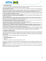
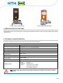
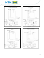
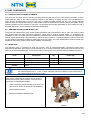
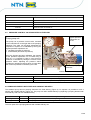
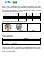
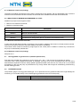
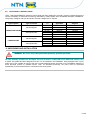
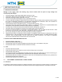
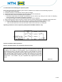
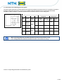
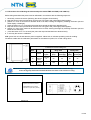
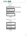
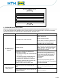
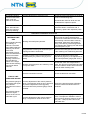
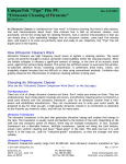
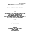
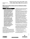
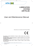
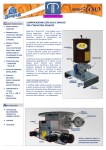
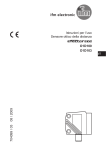
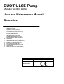
DUO’PULSE Pump
Modular electric pump
User and Maintenance Manual
Guarantee
CONTENTS
1.
2.
3.
4.
5.
6.
7.
8.
9.
10.
11.
12.
13.
14.
15.
16.
17.
INTRODUCTION
GENERAL DESCRIPTION
IDENTIFICATION OF THE MACHINE
TECHNICAL CHARACTERISTICS
PUMP COMPONENTS
UNPACKING AND INSTALLATION
INSTRUCTIONS FOR USE
PROBLEMS AND SOLUTIONS
MAINTENANCE PROCEDURES
DISPOSAL
INFORMATION ABOUT ORDERING
DIMENSIONS
HANDLING AND TRANSPORT
PRECAUTIONS FOR USE
CONTRAINDICATIONS FOR USE
GUARANTEE
DECLARATION OF CONFORMITY
Manufacturer
Product
Certification
Manual compiled in accordance with Directive CE 2006/42
NTN - SNR Roulements
Duo’Pulse Pump
1. INTRODUCTION
This user and maintenance manual refers to the IN’PULSE lubrication system.
This manual should be conserved in such a way that it remains undamaged over time and is readily available to
personnel needing to consult it.
The manufacturer reserves the right to update the product and/or the user and maintenance manual without the
obligation to revise previous versions. Further copies of this manual, updates or clarifications can be obtained by
directly contacting Experts & Tools at NTN-SNR Roulements, or to consult our web site at www.ntn-snr.com.
The use of the equipment referred to in this manual must be entrusted to qualified personnel with a basic knowledge
of mechanics, hydraulics and electrical systems.
It is the responsibility of the installer to use tubing suitable for the system; the use of inadequate tubing can cause
problems with the pump, injury to persons and create pollution.
Loosening of connections can cause serious safety problems; carry out a check before and after installation and, if
necessary retighten them.
Never exceed the maximum working pressure values permitted for the panel and the components connected to it.
Before any maintenance or cleaning operation disconnect the power supply, close off the air supply and discharge
the pressure from inside the equipment and the tubing connected to it.
Do not subject the panel, the connections, the tubing or parts under pressure to violent impacts; damaged tubing or
connections are dangerous and should be immediately replaced.
After long periods of inactivity, check air tightness of all parts subjected to pressure.
Personnel must use personal protection equipment, clothing and tools adequate for the location and the use of the
panel both during its operation and during maintenance operations.
The panel, and any accessories mounted on it, should be carefully checked immediately on receipt and in the event
of any discrepancy or complaint the NTN-SNR Roulements Sales department should be contacted without delay.
NTN-SNR Roulements declines to accept any responsibility for injuries to persons or damage to property in the
event of the non-observance of the information presented in this manual.
Any modification to component parts of the system or the different destination of use of this system or its parts
without prior written authorization from NTN-SNR Roulements will absolve the latter from any responsibility for injury
to persons and/or damage to property and will release them from all obligations arising from the guarantee.
2. GENERAL DESCRIPTION
The Duo’Pulse lubrication pump may be adapted to many uses without making any mechanical changes even after it
has been installed. In fact, the pressure, quantity of lubricant delivered, actual type of lubricant or type of distribution
can be altered.
This construction technique is essentially based on the following modules:
• Electric motor
• Pump body with integrated reducer
• Two pumping elements
• Reservoir
• Valves and outlet unit (inverter, pressure adjustment valve, etc.).
There is only one bearing structure for all versions, with the dual pumping element constituting the essential module.
The pump unit possesses one single output, because the deliveries from the two pumping elements flow into a
manifold unit.
The pump is controlled by normal electrical apparatus which is able to effect inversion and perform the programmed
cycles.
The Duo’Pulse electric pump is fully protected against the external environment and can operate without difficulty
under the most severe environmental conditions.
2/ 26
Picture 1: DUO'PULSE 100 Kg
Picture 2: DUO'PULSE 30 Kg
3. IDENTIFICATION OF THE PUMP
On the front part of the pump tank there is a plate which indicates the product code, the supply voltage and the basic
characteristics.
4. TECHNICAL CHARACTERISTICS
The pump consists of a series of components with the following characteristics:
Max. pressure
Outlet delivery
Working temperature
Working humidity
Viscosity at working
temperature
Technical characteristics
400 bar
400 cm3 / min (24 cu. in/min)
(2 x 200 cm3 (12 cu. in) pump modules )
da - 5° C a + 50° C (da 23° F a +122° F)
90% max
Mineral oil lubricants
Min. 32 cSt
Grease lubricants
Viscosity at working
temperature
Degree of protection
Electric motor
NGLI 2 Max.
IP 55
Three phase
Power:
0.75kW
Protection IP55 class B
Voltage:
230-400 Volt ± 5% 50 Hz
240-440Volt ± 5% 60 Hz
S1 continuous service.
N.B.: do not supply the machine with voltages and pressures different from those indicated
on the plate.
3/ 26
4.1 HYDRAULIC FUNCTION DIAGRAM
Picture 3
Picture 4
Picture 5
Picture 6
4/ 26
5. PUMP COMPONENTS
5.1 FIXED DELIVERY PUMPING ELEMENTS
The pump has two fixed delivery standard pumping elements (200 cm³ min for each pumping element). A piston
slides inside the body of the pumping element coupled to the latter by a lapping process. The seal between the
piston and the pumping body is of a dry type, with no gasket provided between the two. The pumping element
retention valve is of the tapered seal type. This solution is able to guarantee an optimum seal for the system at high
operating pressures (max. pressure of 400 bars). The pumping elements are assembled on the manifold unit with a
threaded attachment, which facilitates its assembly/ dismantling.
5.2
ENDLESS SCREW / WORM WHEEL UNIT
The pump has endless screw-worm wheel working kinematics with a transmission ratio of 1/40. The screw is made
from special steel with high mechanical resistance, which gives it optimum flexible rigidity. To guarantee high
resistance to wear, the screw has been subjected to TENIFER wear-resistant treatment. The screw is supported by
oblique contact ball bearings, duly preloaded, to reduce working clearance. The worm wheel is made of bronze alloy
for gear systems, particularly suitable for making the pump run quietly. The worm wheel shaft is made of special high
resistance steel which gives the pump better reliability and durability.
5.3 INVERTORS
The standard pump is prepared for dual line function, with an electromagnetically controlled inverter being
assembled as standard. The inverter can be replaced if it is not working efficiently, without disconnecting the two line
pipes (of an interchangeable type). This is able to reduce maintenance times and the relating installation shutdown.
Code
Description
Current
(A)
Power (W)
3150011
Electromagnet 24V DC
7
170
3150012
Electromagnet 110V AC 50/60 Hz
2
206
3150013
Electromagnet 230V AC 50/60 Hz
1
176
3133262
Seal kit
GENERAL NOTE FOR ALL INVERTERS: It is advisable to plan a delay in the de-energizing of
the electromagnets from 2 - 5 sec. to allow complete inversion in relation to the closing time of
the pressure gauge at the end of the line.
This version means that the inverter can be replaced
without disconnecting the line pipes. A solution of this
type offers the following advantages:
•
Ease of assembly and dismantling (only the 4 front
Allen screws need to be loosened and tightened);
•
Short replacement time;
•
Minimum installation shutdown time.
Picture 7
5/ 26
Spare electro valves
Code
5.4
Description
3155154
Solenoid 24V DC
3155155
Solenoid 24V AC 50/60 Hz
3155156
Solenoid 110V AC 50/60 Hz
3155157
Solenoid 230V AC 50/60 Hz
PRESSURE CONTROL VALVE MOUNTED ON THE PUMP
Bypass pressure
adjustment nut
Ch 34
Pump group unit
The pump has a pressure control valve, mounted
on the manifold unit on the right side of the pumping
elements. The valve can be easily dismantled for
inspection if required. It is calibrated by turning the
bypass pressure adjustment nut:
• clockwise (increase of pressure)
• anticlockwise (decrease of pressure)
Once the bypass has been calibrated, the position
of the pressure adjustment nut is locked using a
lock nut. It is important to bear in mind that line
inversion is controlled by closing the contacts of the
pressure switch. Adjusting the pressure switch
provides an operating pressure which is lower than
the maximum pressure controlled by this valve.
Extractible pumping
elements
Picture 8
Code
3191311
Description
Pressure 100 ÷ 450 bar (1470 ÷ 6615psi)
3191314
Pressure 50 ÷ 200 bar (735÷ 2940 psi) on request
5.5 PUMPING ELEMENTS WITH FIXED AND VARIABLE DELIVERY.
The standard pump has two pumping elements with fixed delivery (Figure 9). On request it is possible to have a
solution with variable delivery (Figure 10). The pump can offer variable delivery by replacing a pumping element with
fixed delivery with one with variable delivery.
Ref.
Figure 9
Code
295060
Description
Pumping element with variable delivery 100- 200 cm3/min
Figure 10
295040
Pumping element with fixed delivery 200 cm3/min
The main parts of the pumping element with variable delivery are:
6/ 26
•
•
•
•
•
External body of the pumping element assembled with seal threading on the manifold group;
Internal body of the pumping element equipped with delivery adjustment with threaded screws;
Piston;
Non-return valve manufactured with tapered cone seal system;
Spring which guarantees contact between the piston and the control eccentric gear.
Ref.
Code
Description
0295040
Fixed pumping
element unit
Code
3190491
Figure 9
0295024
3191312
0295023
3190491
Figure 10
0295060
Variable
pumping
element unit
Picture 9: Fixed delivery pumping
element
3190494
3190495
0295035
3191312
0295023
Description
OR 2187 gasket in polyurethane
CHPU95
Stop valve cap
Tapered spring
Valve cone
Gasket OR 2187 in polyurethane
CHPU95
Gasket OR 3156 in polyurethane
CHPU95
Gasket OR 3118 in polyurethane
CHPU95
Stop valve cap
Tapered spring
Valve cone
Picture 10: Variable delivery pumping element
7/ 26
5.6 ADJUSTMENT OF PUMPING ELEMENT DELIVERY.
Delivery is adjusted by unscrewing (reducing delivery) or tightening (increasing delivery) the internal pumping
element: each complete turn corresponds to an 11.5% change in delivery. There are two references on the fixed and
mobile pumping element bodies (Figure 8) which allow identification of rotation at every ¼ turn (90°). The internal
pumping element possesses a threaded adjustment of M36x2: each complete turn corresponds to an adjustment of
the pumping element’s stroke of 2 mm. We use the reference height obtained with calibration, between the exterior
of the fixed pumping element and the exterior of the internal pumping element (height X). We use Y to indicate the
actual displacement of the internal pumping element (Y=13-X).
X height measured
mm
Y= 13-X pumping
element adjustment
stroke
% variation of
delivery per
pumping element
13
11
9
7
5
0
2
4
6
8
0
11.5
23
34.5
46
Actual stroke of
pumping
element
mm
17.5
15.5
13.5
11.5
9.5
Effective pumping
element delivery
Cm3/ min
200
176
154
132
108
N.B. Delivery values are valid in the absence of outgoing counter pressure.
Picture 12
Picture 11
Picture 13
5.7 MAXIMUM AND MINIMUM GREASE LEVEL INDICATORS
Standard grease pumps have two types of level:
• Minimum capacitive level;
• Maximum visual level (float).
Code
Description
0295100
Maximum visual level kit (float).
0295120
Minimum capacitive level kit per tank kg 30 (68.1 lb.)
0295110
Minimum capacitive level kit per tank kg 100 (100.02 kg.)
3289166
Capacitive probe
5.7.1 Minimum capacitive level
The minimum level is produced by a capacitive probe, positioned on the end of a pipe mounted on the tank cover.
The capacitive probe is normally closed. When it reaches the minimum level the probe indicates a lack of lubricant.
To make the solution valid for NLGI 2 grease as well, the capacitive probe interfaces with the scraper whose function
is to clean the lower face of the grease probe. If the capacitive probe is replaced then it must be recalibrated (see
calibration procedure).
The minimum level contact is indicated by a light signal on the control panel. In addition it controls any command for
the pump to automatically refill the tank.
8/ 26
5.7.2. Maximum visual level (floating)
The phase for loading the lubricant into the tank is carried out by the operator, with an appropriate pump. Once the
maximum level of lubricant has been reached, the small rod which indicates that the tank is full intervenes.
5.8 INDICATORS OF MINIMUM AND MAXIMUM OIL LEVEL.
Standard oil pumps have two types of level:
• Minimum and maximum level float;
• Maximum visual level (float).
Code
Description
0295100
Maximum visual level kit (float).
0295033
Maximum visual level float
0295150
Level float kit for 30 kg tanks (68.1 lb.) (minimum and maximum level)
0295160
Level float kit for 100 kg tanks (68.1 lb.) (minimum and maximum level)
5.8.1 Minimum and maximum level float
A probe rod with dual float mounted on the pump cover provides a reading of the minimum oil level (reserve) and the
maximum level (which allows the automatic refilling of the tank to be halted).
The minimum level contact is indicated by a light signal on the control panel. In addition it controls any command for
the pump to automatically refill the tank.
5.8.2. Maximum visual level (floating)
See point 5.7.2.
5.7
Stirring paddle for grease and oil (standard performance)
Four tanks are provided with a capacity of 30 and 100 kg. (22 – 66.1 – 220.4 lb) two for oil and two for grease.
The tanks have a stirring paddle and scraper as standard, and they must not be dismantled when they are being
assembled and replaced. Under the stirring paddle a galvanized steel mesh with 0.5 mm holes (0.02 in.) is provided
as standard. In this way the pump is protected from any foreign bodies which might be inadvertently present during
the tank refilling process.
5.8
PRESSURE GAUGE
The pressure gauge is of the glycerine filled type, so it is protected from any pressure leaks which might damage its
functioning. It is mounted directly in the manifold group (positioned on the front of the pump).
Code
3292078
Description
0 -1000 bar ( 0 -14.700 psi)
9/ 26
5.9
ELECTRICAL CONTROL PANEL
“NTN - SNR ROULEMENTS” electrical control panel has been designed to provide a system complete with all the
controls necessary for automatic functioning controlled by safety signals from centralized lubrication installations.
The primary voltage is 400 VAC and 50 Hz, the other voltages are on request.
Type of probe
Type of inverter
electromagnetic
CAPACITIVE PROBE
electropneumatic
electromagnetic
LASER PROBE
electropneumatic
Voltage
V
24 VDC
110 VAC
220 VAC
24 VDC
110 VAC
220 VAC
24 VDC
110 VAC
220 VAC
24 VDC
110 VAC
220 VAC
Code Electrical
apparatus
1637008
1637009
1637010
1637011
1637012
1637013
1637001
1637003
1637004
1637005
1637006
1637007
Code Electric
diagram
1327252
1327253
1327254
1327255
1327256
1327257
1327237
1327247
1327248
1327249
1327250
1327251
6. UNPACKING AND INSTALLATION
WARNING: The unit is only to be opened and repaired by specialist personnel.
No pump assembly operations are envisaged. The pump is fixed on a metal pallet, which allows safe handling using
a forklift. This pallet has been designed so that it can be installed in the installation, being equipped with 4 (four)
holes of Ø 14 mm suitable for fixing to the floor. Provide adequate space (as shown on the installation diagram) to
avoid abnormal posture or possible impact. Then, as described previously, the pump must be connected
hydraulically to the machine and then connected to the control panel.
10/ 26
7. INSTRUCTIONS FOR USE
7.1 GOING INTO OPERATION
Damage to the supply cable and housing may involve contact with live parts at high voltage and
consequently fatal danger:
•
•
•
•
•
•
•
•
•
•
•
•
Check the integrity of the supply cable and the unit prior to use;
If the supply cable or the unit is damaged, do not start up the system!
Replace the damaged supply cable with a new one;
The unit can be opened and repaired only by specialist personnel;
In order to prevent the danger of electrocution due to direct or indirect contact with live parts the electric supply
line must be adequately protected by an appropriate magnetothermal differential switch with threshold of
intervention of 0.03 ampere and max intervention time of 1 second;
The interruption power of the switch must be ≤ 10 kA and rated current In 6 A.
The pump must not be used when submerged in fluids or in a particularly aggressive or explosive/inflammable
atmosphere unless prepared in advance for this purpose by the supplier;
to fix the pump correctly check the pitch dimensions shown in the figures in chapter 12;
Use safety gloves and goggles as indicated in the safety sheet for the lubrication oil;
Do NOT use lubricants which are aggressive towards NBR gaskets, and if in doubt consult the NTN - SNR
Roulements technical office which will supply a detailed list of the recommended oils;
Do not ignore dangers to health and comply with health and safety regulations;
Warning! All the electric components must be earthed. This applies to both the electric components, and to the
control devices. To this end make sure that the earth wire is connected correctly. For safety reasons the earth
conductor must be approximately 100 mm longer than the phase conductors. If the cable is accidentally
removed, the earth terminal must be the last one to be removed.
7.2 ACTION TO BE TAKEN BEFORE START-UP.
•
•
•
•
Check the integrity of the pump.
Refill the tank with suitable lubricant.
Check that the pump is at working temperature and that there are no air bubbles in the pipes.
Check that the electric connection has been carried out correctly.
7.3 USE.
•
•
•
•
•
•
7.4
Check the data sets imposed.
Press the start button on the machine to which the Duo’Pulse pump is connected.
Check that the pump start-up.
Check that the machine is adequately lubricated (if there are still some doubts about its correct functioning you
can contact the NTN - SNR Roulements Technical Office and request a test procedure).
Check that the direction of rotation of the electric motor is the one indicated by the indicator arrow, positioned on
the protective housing of the motor fan;
Check that the hydraulic connection is correct.
ADJUSTMENT/ CALIBRATION OF LEVEL PROBES
7.4.1 Pressure
It is possible to adjust working pressure by rotating the bypass screw clockwise to increase pressure or anticlockwise
to reduce pressure. During this operation pay attention to the pressure gauge positioned on the edge of the pump.
11/ 26
7.4.2 Procedure for calibrating the capacitive probe
Before being assembled the capacitive probe must be calibrated in accordance with the following sequence:
1. connect the sensor electrically;
2. immerse the sensor in the lubricant, down to half of its length;
3. remove the sensor from the lubricant until it skims the surface of the lubricant;
4. at this point there can be two possible types of operation:
• the sensor status does not change: its sensitivity must be reduced (by acting on the screws for adjusting
sensor sensitivity) until its state of excitation is reached
• if its status changes, the sensor already possesses the correct sensitivity
5. after checking that the sensor has been correctly read, the sensor reading must be repeated at least three times
6. Tighten the capacitive probe on the probe carrier rod, complying with the following assembly height:
•
450 mm (from below the cover up to the lower surface of the sensor) for a 30 kg tank
•
900 mm (from below the cover up to the lower surface of the sensor) for a 100 kg tank
Operating instructions for the capacitive probe (model SC18M-C5 PNP NO + NC)
Picture 14
General information about operations
Sensors operating under C for continuous current (4 wires)
They are sensors which are amplified in continuous current and which incorporate,
in addition to the oscillator, the outlet amplifier. They are supplied with 4 wires with
an antivalent function in the NPN or PNP versions. In this operation the sensors
offer as standard characteristics protection against permanent short circuit of the
load, absolute safety against inversion of polarity and protection from the peaks
produced by disconnecting inductive loads. They can be supplied together with
model ALNC – ALTP feeders. They are compatible with programmable controller
inputs.
Picture 15
12/ 26
7.4.3 Procedure for calibrating the laser probe
The laser probe possesses a representative and programming display mounted on board. It is possible to operate in
analogue mode (with signal from 4 to 20 mA) or in digital mode (two outputs and four intervention thresholds).
We attach a table showing the calibration parameters for the laser probe, for 30 and 100 kg tank.
LASER PROBE CALIBRATION
30 kg tank
Pos.
Level
Output
signal
set-up
height X
[mm]
100 kg tank
Quantity of height X Quantity
grease [kg] [mm] of grease
[kg]
A
Maximum
absolute
level
OUT 2=
Fno
Minimum
level
nsP2
200
22
200
81
fsP2
370
11
700
25
B
Maximum
level
nsP1
230
20
230
78
D
Minimum
absolute
level
fsP1
420
8
800
14
C
Picture 16
OUT 1=
Fno
N.B.: In the 30 kg pump tank at minimum absolute level there is still a reserve of 7 kg.
In the 100 kg pump tank at absolute minimum level there is still a reserve of 15 k.g
Picture 17: Operating instructions for the IFM laser probe
13/ 26
Instructions for calibrating the Laser Probe O1D100
Rotate the wording on the Display by 180°.
1.
Press the MODE ENTER key 7 times: EF. appears on the Display.
2.
Press the SET key.
3.
Press the MODE ENTER key 5 times: diS. appears on the Display.
4.
Press the SET key. d3. appears on the Display.
5.
Keep the SET button pressed down for 5 sec.
6.
When the wording on the Display no longer flashes, press SET once.
7.
rd1. appears on the Display.
8.
Press MODE ENTER once.
9.
Check that the Display wording has rotated by 180°.
Calibrate outlet 1 (OUT 1) operating with window nsP1 (B) & fsP1 (D) (see Calibration table for Laser probe)
1.
Press the MODE ENTER key once: OU1 appears on the Display.
2.
Keep the SET button pressed down for 5 sec.
3.
When the wording on the Display no longer flashes, press SET twice until Fno appears on the Display.
4.
Press the MODE ENTER key once: nsP1 appears on the Display.
5.
Keep the SET button pressed down for 5 sec.
6.
When the wording on the Display no longer flashes, press SET once.
7.
The value of the height read appears on the Display.
8.
Press the SET button until the desired height appears.
9.
Press the MODE ENTER button once and the height set is memorised.
10.
Press the MODE ENTER key once: fsP1 appears on the Display.
11.
Repeat the previous points from N° 5 to N° 9.
Calibrate outlet 2 (OUT 2) operating with window nsP2 (A) & fsP2 (C) (see Calibration table for Laser probe)
1.
Press the MODE ENTER key once: OU2 appears on the Display.
2.
Keep the SET button pressed down for 5 sec.
3.
When the wording on the Display no longer flashes, press SET 4 times until Fno appears on the Display.
4.
Press the MODE ENTER key once: nsP2 appears on the Display.
5.
Keep the SET button pressed down for 5 sec.
6.
When the wording on the Display no longer flashes, press SET once.
7.
The value of the height read appears on the Display.
8.
Press the SET button until the desired height appears.
9.
Press the MODE ENTER button once and the height set is memorised.
10.
Press the MODE ENTER key once: fsP2 appears on the Display.
11.
Repeat the previous points from N° 5 to N° 9.
14/ 26
7.4.4 Procedure for calibrating the ultrasound probe model ZWS-70/CI/QS (code 3289173)
Before being assembled the probe must be calibrated in accordance with the following sequence:
1. electrically connect the sensor (following the electric diagram shown below);
2. keep the sensor button pressed down until the two LED (green and yellow lights) flash together;
3. position it in front of the minimum absolute level to be read, entering the height by releasing the button (the two
LEDs display a fixed light);
4. press the button for 3 or 4 seconds (the probe has acquired the Minimum absolute level);
5. keep the sensor button pressed down until the two LED (green and yellow lights) flash together;
6. position it in front of the maximum absolute level to be read, entering the height by releasing the button (the two
LEDs have a fixed light);
7. press the button for 3 or 4 seconds (the probe has acquired the Maximum absolute level);
8. In this way the sensor is calibrated.
N.B.: green Led on indicates that the probe is supplied. Yellow Led on indicates operating mode for reading.
We attach a table with the calibration parameters for the ultrasound probe, for 30 and 100 kg tanks.
Calibration of ultrasound probe
Pos.
30 kg tank
Level
A
Picture 18
B
Output
signal
Maximum
Threshol
absolute
d1
level
Minimum
threshold
absolute
2
level
100 kg tank
height X
[mm]
Quantity of
grease [kg]
50
26
50
95
420
0
800
0
height X Quantity of
grease [kg]
[mm]
N.B.: In the 30 kg pump tank at the minimum absolute level there is still a reserve of 7 kg.
In the 100 kg pump tank at the minimum absolute level there is still a reserve of 15 kg.
Green LED: status indicator.
Signals if the sensor is powered.
Yellow LED: function indicator.
Reports the output status (On/Off).
Picture 20
Picture 19
15/ 26
Windows setting:
START
Place the object on the threshold (1)
During the operational phase,
the sensor detects only objects
between this threshold and (2)
Press the button for about 3 seconds
until the LED blink simultaneously.
(The LED flashes)
Place the object on the threshold (2)
During the operational phase,
the sensor detects only objects
between this threshold and (1)
Press the button for about 1 sec., and
then release it.
(The sensor returns to operation)
END
Output feature selection in ascending or
descending:
START
Press the button for about 13 sec. until the
LED blink simultaneously.
(Only the green LED flashes)
Press the button (for about 1 sec.) to
choose between NA and NC.
Yellow LED: On = ascending
Off = descending
Wait 10 sec.
END
16/ 26
Re-setting to factory settings:
STAR
Remove power.
Press and hold the button while power is applied.
(both LED flashing simultaneously)
Press the button for about 13 sec. while the green LED is constant.
Release the button.
END
8. PROBLEMS AND SOLUTIONS
Below is a diagnostic table showing the main faults, the probable causes and the possible solutions.
In the event of doubts and/or problems which cannot be solved, do not proceed to look for the fault by dismantling
parts of the machine, but contact the NTN - SNR Roulements Technical Office.
Fault
Cause
The electric motor is not functioning.
Solution
Check the connection between motor and
electric supply line.
Check the motor winding.
Check that the connection plates for the
motor terminal box are positioned in
accordance with the supply voltage.
The electric pump is
not delivering any
lubricant.
The tank is empty.
Fill the tank.
N.B.: If the tank was emptied without the
electric signal for reaching the minimum
level being given, the minimum level
contact must be checked.
The pump is not triggered. Causes of the
pump’s failure to trigger:
• The motor is turning in an inverted direction
(clockwise);
• The motor is turning in the right direction
but the stirring paddle is not turning;
• Presence of air bubbles in the lubricant.
Remove the cover from the tank and
check that the stirring paddle is turning
anticlockwise and that the lubricant is
moving; if not invert two of the three
motor phases.
See above.
The pressure adjustment valve (bypass) has
been calibrated at too low a value
Presence of dirt in the non-return valve.
he pump will not go
under pressure.
Remove the pump delivery pipe and
drain off the lubricant until the air bubbles
have been eliminated.
Possible dirt on the cone of the pump stop
valve
Clean the cone and the pumping element
stop valve housing, draining off the
lubricant.
Internal gasket between pumping element and
manifold unit broken.
Replace the gasket
17/ 26
Fault
No signal indicating
minimum level when
there is not any
lubricant in the tank.
Cause
Incorrect adjustment of minimum level.
Selection of minimum
level, with lubricant
below the minimum
and pump working.
Incorrect adjustment of minimum level.
Solution
Check the correct functioning of the level
probe in the following way:
Dismantle the minimum level unit and
recalibrate the capacitive probe.
The light on the control panel is still on:
check the electric connection and, if
necessary, replace the capacitive probe.
Lubrication installation accessories
Metering unit small piston jammed.
Replace the metering unit with another
one having the same characteristics.
However it is advisable to make sure that
the metering units have been correctly
assembled, particularly with regard to
fixing. Over-locking of the fixing screws
may damage the metering unit and cause
the small piston to jam.
Piping between metering unit outlet and point
requiring lubrication obstructed.
Remove the outlet pipe and check to see
if the metering unit is delivering lubricant.
Pressure on the line too low (the lubricant is
not delivered by any outlet or only by a few
outlets).
Change the pressure control valve
adjustment (bypass) or the adjustment of
the control pressure gauge (and of line).
Metering unit arranged for two outlets by used
for only one outlet.
Check that, when one single outlet is
used, the right pad is assembled and that
the other outlet is sealed. See instruction
sheet for AG6 metering units.
Electrical connection incorrect.
Check the electrical connection.
Incorrect adjustment of the control pressure
gauge. The pressure value set is too high and
the pressure adjustment valve (bypass)
intervenes before the pressure gauge can be
activated.
Reduce the pressure gauge calibration
pressure until an electrical contact is
obtained.
Incorrect adjustment of the control pressure
gauge. The pressure value set is too low.
Increase the pressure gauge calibration
valve. The optimum calibration value is
the one which allows a pressure of 50-70
bar (735 – 1029 psi) at the end of the
lubrication line.
METERING UNIT
AG6
Alarm signal indicating
non-delivery of
lubricant. The small
rods visible inside the
metering unit turrets
must move
sequentially up and
down and activate the
control microswitch
when the pump is
working. If this is not
the case the two
outlets or the single
outlet of that metering
unit will not deliver
lubricant.
END OF LINE
PRESSURE GAUGE
The pressure gauge is
not sending the signal
to the electric
command and control
panel.
The pressure gauge
sends the signal
before the end of the
lubrication cycle.
18/ 26
9. MAINTENANCE PROCEDURES
Use the individual protective devices needed to avoid contact with mineral oil or grease.
Regular inspection
The following regular checks must be carried out:
Check
the lubrication status
Cleanliness of the loading and suction filter
1000 hours
4000 hours
The machine does not require any special equipment for any checking and/or maintenance activity, however the
recommendation is to use suitable equipment which is in a good condition in order to avoid causing damage to
persons or machine parts (according to current regulation).
If necessary clean the tank paying due attention (when the machine is off and without it being possible to restart it).
Remember to reseal the tank once the operation has been completed.
Make sure that the electric and hydraulic supply has been disconnected before carrying out any
maintenance intervention.
10. DISPOSAL
In the course of machine maintenance, or if the machine is scrapped, do not dispose of polluting parts into the
environment. Refer to local regulations with regard to their correct disposal. When scrapping the machine the
identification plate and any other documents must be destroyed.
19/ 26
11. INFORMATION ABOUT ORDERING
Equipment
Duo’Pulse Pump
Standard equipment
Description
400 cm3/min grease pump 30 Kg (66lb) tank with inverter code 0083420 at
24 V DC
400 cm3/min grease pump 100 Kg (220lb) tank with inverter code 0083420
at 24 V DC
400 cm3/min grease pump 80 Kg (176lb) tranrent reservoir with inverter
code 0083420 at 24 V DC
400 cm3/min oil pump 30 Kg (66lb) tank inverter code 0083420 at 24 V DC
Duo’Pulse
trolley mounted
Electromagnetic
inverter for base
Transparent
reservoir
Dual Line
electric Inverter
Pneumatic
inverter
Code
2477000
2477001
2477100
2477050
400 cm3/min oil pump 100 Kg (220lb) tank with inverter code 0083420 at
24 V DC
2477051
DUO’PULSE ATEX Pump in Stainless Steel 316
2477201
Duo’Pulse Pump 30 Kg sheet metal reservoir with inverter code 0083420 at
24 V DC
24V DC
110V AC 50/60Hz
230V AC 50/60HZ
Instrumentation and optional
Reservoir, including the tank (PN# 0295056) and all accessories required
for use( flanges, screws, nuts, seals)
24V DC
110V AC 50/60Hz
230V AC 50/60HZ
24V DC
24V AC 50/60Hz
110V AC 50/60Hz
230V AC 50/60HZ
1525212
0083420
0083421
0083422
0295210
0083400
0083401
0083402
0083450
0083451
0083452
0083453
Ultrasound level
Ultrasound level with continuous reading 4..20 mA
0295140
Laser level
Laser level with 2 digital outlets with 4 thresholds or 4..20 mA
0295130
Heater module
Heater module for low temperatures < –5°C (23° F)
Reserve pumping module 200cm3/min (24 cu. in)
Variable pumping module 100-200cm3/min (12-24 cu. in)
Closure cap for fixed delivery pumping element
Closure cap for variable delivery pumping element
Min/max oil level float kit 30 Kg (66lb)
Min/max oil level float kit 100 Kg (99.79kg)
Filling cap with filter
Pumping
element
modules
Oil conversion
Terminal Box
bracket
Electrical control
box Bracket
Metal pallet
0295065
0295040C
0295060
0295024
0295035
0295150
0295160
3130138
Bracket for installing a terminal wiring box onto the base pallet
3044455
Bracket for installing a control box onto the base pallet
3044456
Metal Pallet used as the base of the packaging and also for installation of
the pump.
0043446
20/ 26
SPARE PARTS
Spares description
Minimum level kit 30 kg (grease)
Minimum level kit 100 kg (grease)
Maximum level kit 30-100 kg (grease)
Minimum and maximum laser level kit 30kg
Minimum and maximum laser level kit 100kg
Minimum and maximum ultrasound level kit 30kg
Minimum and maximum ultrasound level kit 100kg
Maximum mechanical level kit 30-100 kg (grease)
Maximum and minimum float level kit 30 kg (oil)
Maximum and minimum float level kit 100 kg (oil)
Grease loading filter
By-pass re kit
Manifold kit
Tank flange gasket
Manifold gasket (pump body)
Manifold gasket (pumping)
295009 Filter gasket
Filter cover gasket
Worm screw assembly cover gasket
Body-pump reservoir gasket
Helicoidal gear assembly
Worm screw assembly
Part number
0295120
0295110
0295170
0295180
0295130
0295140
0295190
0295100
0295150
0295160
0295009
0295196
0295195
3190487
0018863
3190489
3190487
0061135
3190488
3190485
0295020
0295010
21/ 26
Picture 21: pump body secondary unit
Picture 22: Worm wheel group unit
Picture 23: Endless screw unit
22/ 26
12. DIMENSIONS
To facilitate future maintenance, increase the spaces indicated by at least 200 mm (7.87 in.).
A
Picture 25
B
C
D
Dimensions mm (inches)
900 (35.43), 30 kg tank
1350 (53.14), 100 kg tank
615 (24.21), 30-100 kg tank
450 (17.71), 30-100 kg tank
148.5 (5.84), 30-100 kg tank
Picture 24
Electric system – Technical data
Electrical supply:
Power absorbed:
230-400 Volt ± 5% 50 Hz
240-440 Volt ± 5% 60 Hz
0.75 kW
13. HANDLING AND TRANSPORT
A metal pallet is used for transport and storage with packing at the side and a wooden cover.
The pump is fixed on a metal pallet, which allows safe handling using a forklift. The metal pallet has been designed
so that it can be installed in the installation, being equipped with 4 (four) holes of Ø 14 mm suitable for fixing to the
floor.
The machine components can withstand temperatures, during storage, from -20 to + 50 °C (-4°F - 122°F); it is
therefore necessary, in order to avoid damages, for the machine to be started up when the machine has reached a
minimum temperature of +5 °C (+41°F).
14. PRECAUTIONS FOR USE
It is necessary to carefully read the warnings and risks associated with using a lubricant pump. The operator must
understand how it works and must clearly understand the dangers by studying the user manual.
23/ 26
15. CONTRAINDICATIONS FOR USE
The check on compliance with the essential safety requirements and with the stipulations indicated in the machine
directives are to be carried out by means of compiling the checklists already made available and contained in the
technical file.
Three types of lists were used:
• list of dangers (section from EN 414 relating to EN 292)
• Application of the essential safety requirements Machine Dir. - app. 1, part 1)
• electrical safety stipulations (EN 60204-1)
See below a list of dangers which have not been completely eliminated, but are considered acceptable:
• During assembly/maintenance it is possible that there may be an oil splash (consequently this operation must be
carried out using appropriate individual protective devices);
• contact with oil -> see instructions for using appropriate individual protective devices DPI;
• Use of an inappropriate lubricant -> fluid characteristics indicated both on the pump and in the manual (if in
doubt consult our Technical Office);
• protection against direct and indirect contact must be provided by the user;
• whenever the cover is opened for an intervention resealing the catch is essential;
• The pump’s working logic requires it to operate at all times, so it is necessary to pay attention to the electric
connection. If there is no current the customer’s machine can only be restarted following a reset while the
lubrication pump can restart automatically.
Unacceptable fluids
Fluids
Lubricant with abrasive additives
Lubricant with silicon additives
Benzine – solvents – inflammable liquids
Corrosive products
Water
Food substances
Dangers
High consumption of contaminated parts
Jamming of the pump
Fire – explosion – damage to gaskets
Corrosion of the pump – injuries to persons
Pump oxidation
Contamination of these substances
24/ 26
16. GUARANTEE
All NTN - SNR Roulements products are guaranteed for a maximum of 12 months from the delivery date, for
constructional and material faults.
The guarantee is extended as indicated below:
Complete installation of the system by NTN - SNR Roulements: 24 months.
Other components: 12 months from the date of installation; if installation takes place 6 months or more following the
delivery date, the guarantee will cover a maximum of 18 months from the delivery date.
In the event of equipment malfunction we must be notified of precise details of the fault encountered, supplying the
NTN - SNR Roulements code, the test number if present (expressed as: xxxxxx-xxxxxx), delivery and installation
date and, finally, conditions of using the product/s in question.
Once this information has been received we will decide at our own discretion whether to provide technical assistance
or not.
After receiving the equipment and on the basis of careful analysis NTN - SNR Roulements reserves the right to
decide whether to repair or replace the product. If the guarantee is still valid we will proceed to repair or replace the
part at our own expense.
If the returned product is not faulty, NTN - SNR Roulements will decide at its own discretion whether or not to charge
the customer for the costs incurred (logistics, etc.).
This guarantee must be understood to be cancelled if the product shows signs of damage and resulting from
incorrect use, negligence, normal wear and tear, chemical corrosion, installation not in compliance with the
instructions expressly indicated and use contrary to the manufacturer’s recommendations. Any changes, tampering
or alterations to the equipment or its parts made without written authorisation from NTN - SNR Roulements, relieves
the latter from all liability and releases it from the obligations of the guarantee.
Parts subject to normal wear and tear and perishable parts are not covered by the guarantee.
Anything not expressly indicated must be considered to be excluded from the guarantee as well as damages or costs
resulting from faults in the actual product.
The conditions of validity of the NTN - SNR Roulements guarantee are understood to be implicitly accepted as soon
as the equipment is purchased. Any changes to or departures from this guarantee must only be considered valid
after prior authorisation from NTN - SNR Roulements.
NTN - SNR ROULEMENTS declines any liability for personal injuries or damages to property in the event of failure to
comply with the instructions provided in this manual.
Any changes to the component parts of the system or a change in the intended use of the latter or its parts without
written authorisation from NTN - SNR ROULEMENTS relieve the latter from any liability for personal injuries and/or
damage to property and relieve it of any guarantee obligation.
25/ 26
17. DECLARATION OF CONFORMITY
DECLARATION OF CONFORMITY
NTN-SNR Roulements, registered in Annecy, rue des Usines,
CERTIFIES:
That the machines DUO’PULSE pump
Has been constructed in conformity with the directives of the council of the European community on the standardization
of the legislation of member states:
- 98/37/CE
- BT 73/23/CEE
Machines
Low voltage
Has been manufactured, as applicable in accordance with the following standards and harmonised technical
specifications: EN292-1/2, EN 1050, EN 982, EN 11200, EN 60947, EN 894 1/2
----------------------------------------------------------------------------------------------------------------------------------------------------------------------------
Web site: http://www.ntn-snr.com
E-mail: [email protected]
26/ 26