1
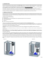
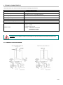
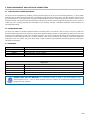
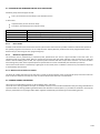
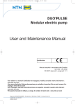
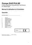
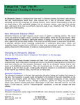
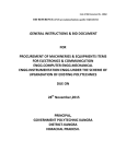
Sumo Pump
Modular electric pump
Version in compliance with Directive CE 94/9 (ATEX)
User and Maintenance Manual
Original text translation
Guarantee
CONTENTS
1.
2.
3.
4.
5.
6.
7.
8.
9.
10.
11.
12.
13.
14.
15.
16.
17.
INTRODUCTION
GENERAL DESCRIPTION
IDENTIFICATION OF THE MACHINE AND MARKING
TECHNICAL CHARACTERISTICS
PUMP COMPONENTS AND ELECTRICAL CONNECTIONS
UNPACKING AND INSTALLATION
INSTRUCTIONS FOR USE
PROBLEMS AND SOLUTIONS
MAINTENANCE PROCEDURES
DISPOSAL
INFORMATION ABOUT ORDERING
DIMENSIONS
HANDLING AND TRANSPORT
PRECAUTIONS FOR USE
GUARANTEE
DECLARATION OF CONFORMITY
DISTRIBUTORS
II 2GD ck IIC T100 °C IP65
Manual compiled in accordance with Directive
CE 06/42
C2137IE – WK 16/11
1. INTRODUCTION
This user and maintenance manual relates to the Sumo Pump, version in compliance with ATEX standards. The Sumo Pump
allows oil and grease to be distributed within lubrication systems at pressures of up to 400 bar (5880 psi). The latest version
may be obtained from Dropsa Sales Office, or by consulting our web site http://www.dropsa.com.
The instructions in this manual must be studied and carried out by qualified personnel basic hydraulic and electrical
knowledge. A detailed understanding of concepts and working practices for ATEX systems and hazardous area is necessary.
This user and maintenance manual contains important information about protecting the health and safety. You must read and
look after it carefully, making sure that it is available at all times for any operators that may need to consult it.
2. GENERAL DESCRIPTION
The Sumo series of lubrication pumps offers flexible configuration options and is therefore well suited to many uses in
lubrication systems. This can be achieved easily, by adding a number of accessories and components which can be assembled
at any time onto the pump unit.
This Pump consists of the following:
Electric motor
Pump body manifold with integrated pressure adjustment (bypass) and instrumentation
Two pumping elements
Reservoir
Dual Line Pressure inverter valve
There is only one bearing and cam structure for all versions that operate the dual pumping modules.
The pump unit possesses one single output, because the deliveries from the two pumping elements flow into a manifold unit
that sums the output from both pump modules. This offers redundancy should one pumping module fail, for example due to
contamination in the grease damaging the pump bore.
Two types of tank for grease and oil with different volumes (of 30 or 100 kg) with stirring paddle and level indicators are
available.
The pump can be controlled manually, via customer PLC or with the addition of a Dropsa Control system according to the
system in use.
Custom designed units are available included built in electronic or electrical control systems (eg see fig.2.2). If you have such a
unit you should refer to the Pump drawing supplied with the unit that will outline the customization and the wiring
information if required.
The Sumo electric pump is fully protected against the external environment and can operate without difficulty under the most
severe environmental conditions. The SUMO Atex Pump has been designed for use in particularly harsh environments (such as
off-shore and marine applications) and can be operated in hazardous areas subject to verification of correct zone classification
and requirements. The Pump manifold body, pump modules and directional reversing valves are made in Stainless Steel 316L .
Other external parts exposed to corrosive atmosphere are painted with high grade paint typically used on marine applications.
The pump is shipped on a stainless steel base structure which is also used to connect terminal wiring box support and lifting
lugs.
Figure 2.1
Figure 2.2
2/ 21
3. IDENTIFICATION OF THE MACHINE AND MARKING
On the front part of the pump tank there is a plate which indicates the product code, the supply voltage and basic
characteristics.
On the pallet there is the plate refers at the ATEX marking (Figure 3.1)
Figure 3.1
ck
3.1
ATEX Information
II
Group of equipment for surface (not for mines or underground)
2GD
equipment for explosive atmosphere due to flammable gas and combustible dust. 2GD Category is
appropriate for zones classified as 1 zone ( 2 zone included) and 21 zone ( 22 zone included).
c
Protection mode designed for the method of construction ( EN 13463-5 normative).
k
Protection mode designed by oil immersion (EN 13463-8 normative).
IIB+H2
Group of flammable gas allowed IIB with hydrogen ( IIA group gas included)
T5
Max. surface temperature for flammable gas
T 100 °C Max. surface temperature for combustible dust
IP65
Protection grade ( view note)
Note : IP65 protection grade is referred to electric parts. Not electric parts are protected from combustible dust by the type of
process that provides for the continued presence of oil and grease on the mechanical ignition sources.
3/ 21
4. TECHNICAL CHARACTERISTICS
The pump consists of a series of components with the following characteristics:
Max. pressure
Outlet delivery
Working temperature
Working humidity
Viscosity at working temperature
Degree of protection
Electric motor
Technical characteristics
400 bar
400 cm3 / min (24 cu. in/min)
(2 x 200 cm3 (12 cu. in) pumping modules )
from - 5° C to + 50° C (from 23° F to +122° F)
90% max
Grease Lubricants
NGLI 2 Max.
IP65
Three phase
Power 0.75kW
Protection IP55 class B
Voltage: 230-400 Volt ± 5% 50 Hz
240-440Volt ± 5% 60 Hz
S1 continuous service.
WARNING: do not supply the machine with voltages and pressures different from those indicated on the
plate.
4.1 HYDRAULIC FUNCTION DIAGRAM
4/ 21
5. PUMP COMPONENTS AND ELECTRICAL CONNECTIONS
5.1 FIXED DELIVERY PUMPING ELEMENTS
The pump has two fixed delivery standard pumping elements (200 cm^3/ min for each pumping element). A piston slides
inside the body of the pumping element that is matched by a high precision honing process. The seal between the piston and
the pumping body is of a dry type, with no gasket provided between the two. The pumping element retention valve is of the
tapered seal type. This solution is able to guarantee an optimum seal for the system at high operating pressures (max. pressure
of 400 bar). The pumping elements are assembled on the manifold unit with a threaded attachment, which facilitates its
assembly/ dismantling.
5.2 WORM WHEEL UNIT
The pump has endless screw-worm wheel kinematic mechanism with a transmission ratio of 1/40. The screw is made from
special steel with high mechanical resistance, which gives it optimum flexible rigidity. To guarantee high resistance to wear, the
screw has been subjected to Tenifer wear-resistant treatment. The screw is supported by oblique contact ball bearings, duly
preloaded, to reduce working clearance. The worm wheel is made of bronze alloy for gear systems, particularly suitable for
making the pump run quietly. The worm wheel shaft is made of special high resistance steel which gives the pump better
reliability and durability.
5.3 INVERTORS
Code
0083470
0083471
0083472
0083473
Description
Electro pneumatic
Electro pneumatic
Electro pneumatic
Electro pneumatic
inverter 24V DC
inverter 24V AC
inverter 110V AC
inverter 230V AC
Spare parts
Code
3150108
3150109
3150110
3150111
Description
ATEX coil EExm 24 V DC
ATEX coil EExm 24 V AC
ATEX coil EExm 110 V AC
ATEX coil EExm 230 V AC
GENERAL NOTE FOR ALL INVERTERS: It is advisable to plan a delay in the de-energizing of the
electromagnets from 2 ÷ 5 sec. to allow complete inversion in relation to the closing time of the pressure
gauge at the end of the line.
5/ 21
5.3.1 General characteristics
Figure 5.1
The main parts of the device are:
An AISI 316L distribution central body with a steel
piston with antiwear treatment.
two simple effect pneumatic actuation cylinders,
controlled by a 5/ 2 type electro valve with certificate
explosive environment coil..
electro valve with air inlet Ø4 tube. Inlet air pressure
must be:5÷7 bar.
Spare electro valves
Code
3155222
5.4
Description
Solenoid 5/2
PRESSURE CONTROL VALVE MOUNTED ON THE PUMP
Figura 5.2
Pump group unit
The pump has a AISI 316L pressure control valve,
mounted on the manifold unit on the right side of the
pumping elements. The valve can be easily dismantled
for inspection if required. It is calibrated by turning the
bypass pressure adjustment nut:
clockwise (increase of pressure)
anticlockwise (decrease of pressure)
Once the bypass has been calibrated, the position of the
pressure adjustment nut is locked using a lock nut. It is
important to bear in mind that line inversion is
controlled by closing the contacts of the pressure
switch. Adjusting the pressure switch provides an
operating pressure which is lower than the maximum
pressure controlled by this valve.
Code
3191323
Description
Pressure 100 ÷ 450 bar (1470 ÷ 6615 psi)
3191324
Pressure 50 ÷ 200 bar (735÷ 2940 psi) on request
Bypass pressure
adjustment nut Ch 34
Extractible pumping
elements
6/ 21
5.5 MAXIMUM AND MINIMUM GREASE LEVEL INDICATORS
Standard pumps have two types of level:
Laser (for minimum and max level) on the standard version
In alternative
capacitive level ( for the minimum level)
Float with microswitch (for the maximum level)
Code
0295145
0295105
0295165
0295155
5.5.1
Description
Laser level kit , 30 kg tank, cover Exd (Minimum and Maximum)
Laser level kit ,100 kg tank, cover Exd (Minimum and Maximum)
Exi Capacitive level kit (Minimum)+Microswitch Exd (Max) 30 Kg
Exi Capacitive level kit (Minimum)+Microswitch Exd (Max) 100 Kg
Laser Probe
Located inside the ExD enclosure the laser level kit optical sensor with connector provides a distance readout that equates to
the quantity of grease in the reservoir. It has a alphanumeric display with four positions and can be programmed to read a
distance of up to 10m using the four programming keys.
5.5.2
Minimum capacitive level
The minimum level is produced by a capacitive probe, positioned on the end of a pipe mounted on the tank cover. The
capacitive probe is normally closed. When it reaches the minimum level the probe indicates a lack of lubricant. To make the
solution valid for NLGI2 grease as well, the capacitive probe interfaces with the scraper whose function is to clean the lower
face of the grease probe. If the capacitive probe is replaced then it must be recalibrated (see calibration procedure).
The minimum level contact is indicated by a light signal on the control panel. In addition it controls any command for the pump
to automatically refill the tank.
5.5.3 Maximum level with microswitch
The phase for loading the lubricant into the tank is carried out by the operator, with an appropriate pump. Once the maximum
level of lubricant has been reached, the small rod which indicates that the tank is full intervenes.
5.6 STIRRING PADDLE FOR GREASE
Two tanks are provided with capacity of 30 and 100 kg. (66.1 – 220.4 lb).
The tanks have a stirring paddle and scraper as standard, and they must not be dismantled when they are being assembled and
replaced. Under the stirring paddle a galvanized steel mesh with 0.5 mm holes (0.02 in.) is provided as standard. In this way the
pump is protected from any foreign bodies which might be inadvertently present during the tank refilling process.
7/ 21
5.7
PRESSURE GAUGE
The pressure gauge is of the glycerine filled type, so it is protected from any pressure leaks which might damage its
functioning. It is mounted directly in the manifold group (positioned on the front of the pump).
Code
Description
3292154
5.8
Pressure gauge 0÷600 bar (0÷8820 psi)
II 2 GD c
ELECTRICAL CONTROL PANEL
On the pallet structure is a increased safety terminal box that contains a terminal board to connect the electrical components
of the Sumo Atex assembly (Motor, valves, level indicators, etc)
Code
1525267
Description
Polyester Cover Exe with terminal board
In figure 5.3 you can see the electrical connections of the standard model. ( See Cap.11 Information about ordering)
Figure 5.3
In figure 5.4 you can see the electrical connections of the alternative model. ( See Cap.11 Information about ordering)
Figure 5.4
WARNING: the distance of path in air trough terminal insulating surfaces at 15 and 16 Intrinsic Security
(capacitance sensor at Intrinsic Security) must be greater than 50mm from other terminals/circuits.
8/ 21
5.8 EARTH CONNECTIONS
In the 5.5 figure is underline the positioning of the bar of grounding
For a complete vision refer to assembly design
Figure 5.5
BAR OF GROUNDING
6. UNPACKING AND INSTALLATION
WARNING: The unit is only to be opened and repaired by specialist personnel.
No pump assembly operations are envisaged. The pump is fixed on a metal pallet, which allows safe handling using a
transpallet or forklift truck. This pallet has been designed so that it can be installed in the installation, being equipped with 4
(four) holes of Ø 14 mm suitable for fixing to the floor. Provide adequate space (as shown on the installation diagram) to avoid
abnormal posture or possible impact. Then, as described previously, the pump must be connected hydraulically to the machine
and then connected to the control panel.
9/ 21
7. INSTRUCTIONS FOR USE
7.1 GOING INTO OPERATION
Damage to the supply cable and housing may involve contact with live parts at high voltage and consequently fatal danger:
Check the integrity of the supply cable and the unit prior to use;
If the supply cable or the unit is damaged, do not start up the system!
Replace the damaged supply cable with a new one;
The unit can be opened and repaired only by specialist personnel;
In order to prevent the danger of electrocution due to direct or indirect contact with live parts the electric supply line
must be adequately protected by an appropriate magneto thermal differential switch with threshold of intervention of
0.03 ampere and max intervention time of 1 second;
The interruption power of the switch must be 10 kA and rated current In = 6 A.
The pump must not be used when submerged in fluids or in a particularly aggressive or explosive/inflammable
atmosphere unless prepared in advance for this purpose by the supplier;
to fix the pump correctly check the pitch dimensions shown in the figures in chapter 12;
Use safety gloves and goggles as indicated in the safety sheet for the lubrication oil;
Do NOT use lubricants which are aggressive towards NBR gaskets, and if in doubt consult the Dropsa SpA technical office
which will supply a detailed list of the recommended oils;
Do not ignore dangers to health and comply with health and safety regulations;
Warning! All the electric components must be earthed. This applies to both the electric components, and to the control
devices. To this end make sure that the earth wire is connected correctly. For safety reasons the earth conductor must be
approximately 100 mm longer than the phase conductors. If the cable is accidentally removed, the earth terminal must be
the last one to be removed.
7.2 ACTION TO BE TAKEN BEFORE START-UP.
Check the integrity of the pump.
Refill the tank with suitable lubricant.
Check that the pump is at working temperature and that there are no air bubbles in the pipes.
Check that the electric connection has been carried out correctly.
7.3 USE.
check the data sets imposed.
press the start button on the machine to which the Sumo pump is connected.
check pump start-up.
check that the machine is adequately lubricated (if there are still some doubts about its correct functioning you can
contact the Dropsa S.p.A Technical Office and request a test procedure).
check that the direction of rotation of the electric motor is the one indicated by the indicator arrow, positioned on the
protective housing of the motor fan;
check that the hydraulic connection is correct.
7.4
ADJUSTMENT/ CALIBRATION OF LEVEL PROBES
7.4.1 Pressure
It is possible to adjust working pressure by rotating the bypass screw clockwise to increase pressure or anticlockwise to reduce
pressure. During this operation pay attention to the pressure gauge positioned on the edge of the pump.
7.4.2 Procedure for calibrating the laser probe
The laser probe possesses a representative and programming display mounted on board. It is possible to operate in analogue
mode (with signal from 4 to 20 mA) or in digital mode (two outputs and four intervention thresholds).
We attach a table showing the calibration parameters for the laser probe, for 30 and 100 kg tank
10/ 21
Figure 3
LASER PROBE CALIBRATION
Serbatoio 30 kg
Pos.
Level
A
Maximum
absolute
level
Output
signal
Serbatoio 100 kg
set-up height X Quantity height X Quantity of
grease [kg]
[mm] of grease [mm]
[kg
nsP2
200
22
200
81
OUT 2= Fno
C
Minimum
level
fsP2
370
11
700
25
B
Maximum
level
nsP1
230
20
230
78
D
Minimum
absolute
level
fsP1
420
8
800
14
OUT 1= Fno
NOTE: In the 30 kg pump tank at minimum absolute level there is still a reserve of 7 kg.
In the 100 kg pump tank at absolute minimum level there is still a reserve of 15 k.g
7.4.3 Capacitive probe
The capacitance level probe has a Namur NO Type Intrinsically safe capacitance sensor :
II 1G EEx ia IIC T6.
Figure 4 (electric connection)
WARNERING: The level probes do not have to be in some way tampered with from the user. They are not
therefore possible repairs or variations of calibration of the same probes. For any information, to contact the
technical office/trades them of the Dropsa SpA.
11/ 21
8. PROBLEMS AND SOLUTIONS
Below is a diagnostic table showing the main faults, the probable causes and the possible solutions.
In the event of doubts and/or problems which cannot be solved, do not proceed to look for the fault by dismantling parts of
the machine, but contact the Dropsa Technical Office.
Fault
The electric pump is not
delivering any lubricant.
Cause
The electric motor is not functioning.
Solution
Check the connection between motor and
electric supply line.
Check the motor winding.
Check that the connection plates for the
motor terminal box are positioned in
accordance with the supply voltage.
The tank is empty.
The pump is not triggered. Causes of the pump’s
failure to trigger:
The motor is turning in an inverted direction
(clockwise);
The motor is turning in the right direction but
the stirring paddle is not turning;
Presence of air bubbles in the lubricant.
The pump will not go
under pressure.
The pressure adjustment valve (bypass) has been
calibrated at too low a value
Presence of dirt in the non-return valve.
Possible dirt on the cone of the pump stop valve
Internal gasket between pumping element and
manifold unit broken.
Fill the tank.
N.B.: If the tank was emptied without the
electric signal for reaching the minimum
level being given, the minimum level contact
must be checked.
Remove the cover from the tank and check
that the stirring paddle is turning
anticlockwise and that the lubricant is
moving; if not invert two of the three motor
phases.
See above.
Remove the pump delivery pipe and drain off
the lubricant until the air bubbles have been
eliminated.
Clean the cone and the pumping element
stop valve housing, draining off the lubricant.
Replace the gasket (code 3190489).
12/ 21
Fault
No signal indicating
minimum level when
there is no lubricant in
the tank.
Cause
Incorrect adjustment of minimum level.
Solution
Check the correct functioning of the level
probe in the following way:
Dismantle the minimum level unit and
recalibrate the capacitive probe.
Selection of minimum
Incorrect adjustment of minimum level.
level, with lubricant
below the minimum and
pump working.
The light on the control panel is still on:
check the electric connection and, if
necessary, replace the capacitive probe.
Lubrication installation accessories
METERING UNIT AG6
Alarm signal indicating
non-delivery
of
lubricant. The small rods
visible
inside
the
metering unit turrets
must move sequentially
up and down and
activate the control
microswitch when the
pump is working. If this
is not the case the two
outlets or the single
outlet of that metering
unit will not deliver
lubricant.
Metering unit small piston jammed.
Replace the metering unit with another one
having the same characteristics. However it
is advisable to make sure that the metering
units have been correctly assembled,
particularly with regard to fixing. Overlocking of the fixing screws may damage the
metering unit and cause the small piston to
jam.
Piping between metering unit outlet and point Remove the outlet pipe and check to see if
requiring lubrication obstructed.
the metering unit is delivering lubricant.
Pressure on the line too low (the lubricant is not Change the pressure control valve
delivered by any outlet or only by a few outlets).
adjustment (bypass) or the adjustment of the
control pressure gauge (and of line).
Metering unit arranged for two outlets by used for
only one outlet.
Check that, when one single outlet is used,
the right pad is assembled and that the other
outlet is sealed.
See instruction sheet for AG6 metering units.
END OF LINE PRESSURE
GAUGE
The pressure gauge is Electrical connection incorrect.
not sending the signal to
the electric command
and control panel.
Check the electrical connection.
The pressure gauge
sends the signal before Incorrect adjustment of the control pressure Reduce the pressure gauge calibration
the
end
of
the gauge. The pressure value set is too high and the pressure until an electrical contact is
lubrication cycle.
pressure adjustment valve (bypass) intervenes obtained.
before the pressure gauge can be activated.
Incorrect adjustment of the control pressure
gauge. The pressure value set is too low.
Increase the pressure gauge calibration
valve. The optimum calibration value is the
one which allows a pressure of 50-70 bar
(735 – 1029 psi) at the end of the lubrication
line.
13/ 21
9. MAINTENANCE PROCEDURES
Use the individual protective devices needed to avoid contact with mineral oil or grease.
Regular inspection
The following regular checks must be carried out:
Check
the lubrication status
Cleanliness of the loading and suction filter
Clamping cable gland *
Cables and wiring integrity
Secure connection to ground
Bearing s motor
1000 hours
4000 hours
4000 hours
4000 hours
4000 hours
3 years
*For M16x1.5 cable gland (Cod. 39384), clamp to 10 Nm.
For M20x1.5 cable gland (Cod. 75053), clamp to 12 Nm.
The machine does not require any special equipment for any checking and/or maintenance activity, however the
recommendation is to use suitable equipment which is in a good condition in order to avoid causing damage to persons or
machine parts (according to current regulation).
If necessary clean the tank paying due attention (when the machine is off and without it being possible to restart it).
Remember to reseal the tank once the operation has been completed.
Make sure that the electric and hydraulic supply has been disconnected before carrying out any maintenance intervention.
WARNING: In case of motor broking is necessary send it to Dropsa for repairing. For further information
contact Dropsa technical/sales office .
10. DISPOSAL
In the course of machine maintenance, or if the machine is scrapped, do not dispose of polluting parts into the environment.
Refer to local regulations with regard to their correct disposal. When scrapping the machine the identification plate and any
other documents must be destroyed.
14/ 21
11. INFORMATION ABOUT ORDERING
Equipment
Sumo Pump
Sumo Pump
Sumo Pump
Sumo Pump
Sumo Pump
Sumo Pump
Sumo Pump
Sumo Pump
Standard equipment
Description
ATEX 400 cm³/min. grease pump 30 Kg (66 lb) tank
Electric pneumatic inverter cod. 0083470 24V DC
Maximum Minimum levels with laser probe in cover Exd cod. kit 0295145
ATEX 400 cm³/min. grease pump 100 Kg (220 lb) tank
Electric pneumatic inverter cod. 0083470 24V DC
Maximum Minimum levels with laser probe in cover Exd cod. kit 0295105
Alternative Equipment
ATEX 400 cm³/min. grease pump 30 Kg (66 lb) tank
Electric pneumatic inverter cod. 0083470 24V DC
Capacitive level kit (minimum)+Microswitch Exd (Max) cod. kit 0295165
ATEX 400 cm³/min. grease pump 100 Kg (220 lb) tank
Electric pneumatic inverter cod. 0083470 24V DC
Capacitive level kit (minimum)+Microswitch Exd (Max) cod. kit 0295155
As the 2477200A000 standard version + Electric pneumatic inverter 24V AC
As the 2477200A000 standard version + Electric pneumatic inverter 110V AC
As the 2477200A000 standard version + Electric pneumatic inverter 230V AC
As the 2477201A000 standard version + Electric pneumatic inverter 24V AC
As the 2477201A000 standard version + Electric pneumatic inverter 110V AC
As the 2477201A000 standard version + Electric pneumatic inverter 230V AC
Code
2477200A000
2477201A000
2477200A100
2477201A100
2477200A010
2477200A020
2477200A030
2477201A010
2477201A020
2477201A030
11.1 SPECIAL VERSION WITH CONTROLLER
Dropsa is able to provide customized versions of the SUMO ATEX Pump that include control equipment, for example the
Vip5ATEX system (shown in photo 11.1.1) .
The equipment is controller by VIP5 Dropsa Controller in explosion configuration ( see Figure 11.1.2 standard version).
The Controller functions, modality and parameters working are explained in the relative manual.
For more information contact the Dropsa sales- technical office or see our website www.dropsa.com
Photo 11.1.1
Photo 11.1.2
15/ 21
11.2 SPARES
Spares description
Laser pump kit level100 kg cover Exd
Laser pump kit level 30 kg cover Exd
Capacitive Exi level kit (minimum)+Microswitch Exd (Max) 100 kg
Capacitive Exi level kit (minimum)+Microswitch Exd (Max) 30 kg
Electric pneumatic inverter 24V DC
Electric pneumatic inverter 24V AC
Electric pneumatic inverter 110V AC
Electric pneumatic inverter 230V AC
Three phase electric motor
Pneumatic motor
Pressure gauge
Pumping unit
Grease loading filter
Assembly loading valve
Tank flange gasket
Manifold gasket (pump body)
Manifold gasket (pumping)
295009 Filter gasket
Filter cover gasket
Worm screw assembly cover gasket
Body-pump reservoir gasket
Code
0295105
0295145
0295155
0295165
0083470
0083471
0083472
0083473
3301531
3301539
3292154
0296040
0295009
3093053
3190487
0018863
3190489
3190487
0061135
3190488
3190485
16/ 21
Body Pump details cod. 0296000
Figure 11.2.1 (Detail of Wormskrew assembly cover)
3190488
0675234
0014225
Figure 11.2.2 (Detail of Manifold gasket pump body
3190487
3190489
0018863
3190489
0018863
0296002
Figure 11.2.3 (Detail login filter gasket)
0061123
0061135
0296004
0295009
3093053
17/ 21
12. DIMENSIONS
To facilitate future maintenance, increase the spaces indicated by at least 500 mm (19,68 in.).
13. HANDLING AND TRANSPORT
A metal pallet is used for transport and storage with packing at the side and a wooden cover.
The pump is fixed on a metal pallet, which allows safe handling using a transpallet or forklift truck. The metal pallet has been
designed so that it can be installed in the installation, being equipped with 4 (four) holes of Ø 14 mm suitable for fixing to the
floor.
The machine components can withstand temperatures, during storage, from -20 to + 50 °C (-4°F - 122°F); it is therefore
necessary, in order to avoid damages, for the machine to be started up when the machine has reached a minimum temperature
of +5 °C (+41°F).
18/ 21
14. PRECAUTIONS FOR USE
It is necessary to carefully read the warnings and risks associated with using a lubricant pump. The operator must understand
how it works and must clearly understand the dangers by studying the user manual.
15. GUARANTEE
All Dropsa products are guaranteed for a maximum of 12 months from the delivery date, for constructional and material faults.
The guarantee is extended as indicated below:
Complete installation of the system by Dropsa: 24 months.
Other components: 12 months from the date of installation; if installation takes place 6 months or more following the delivery
date, the guarantee will cover a maximum of 18 months from the delivery date.
In the event of equipment malfunction we must be notified of precise details of the fault encountered, supplying the Dropsa
code, the test number if present (expressed as: xxxxxx-xxxxxx), delivery and installation date and, finally, conditions of using
the product/s in question.
Once this information has been received we will decide at our own discretion whether to provide technical assistance or to
provide a return authorisation number (RAN) with precise instructions about returning the equipment.
After receiving the equipment and on the basis of careful analysis Dropsa reserves the right to decide whether to repair or
replace the product. If the guarantee is still valid we will proceed to repair or replace the part at our own expense.
If the returned product is not faulty, Dropsa will decide at its own discretion whether or not to charge the customer for the
costs incurred (logistics etc.).
This guarantee must be understood to be cancelled if the product shows signs of damage and resulting from incorrect use,
negligence, normal wear and tear, chemical corrosion, installation not in compliance with the instructions expressly indicated
and use contrary to the manufacturer’s recommendations. Any changes, tampering or alterations to the equipment or its parts
made without written authorisation from Dropsa S.p.A., relieves the latter from all liability and releases it from the obligations
of the guarantee.
Parts subject to normal wear and tear and perishable parts are not covered by the guarantee.
Anything not expressly indicated must be considered to be excluded from the guarantee as well as damages or costs resulting
from faults in the actual product.
The conditions of validity of the Dropsa guarantee are understood to be implicitly accepted as soon as the equipment is
purchased. Any changes to or departures from this guarantee must only be considered valid after prior authorisation from
Dropsa S.p.A.
DROPSA S.p.A. declines any liability for personal injuries or damages to property in the event of failure to comply with the
instructions provided in this manual.
Any changes to the component parts of the system or a change in the intended use of the latter or its parts without written
authorisation from DROPSA S.p.A. relieve the latter from any liability for personal injuries and/or damage to property and
relieve it of any guarantee obligation.
19/ 21
18. DECLARATION OF CONFORMITY
Dropsa Spa
Via Benedetto Croce, 1
20090 Vimodrone (MI)
Italy
Tel.:
Fax Sales:
E-mail:
Web site:
(+39) 02. 250.79.1
(+39) 02. 250.79.767
[email protected]
http://www.dropsa.com
DICHIARAZIONE
DI CONFORMITÁ/DECLARATION OF COMPLIANCE WITH STANDARDS/
DECLARATION DE CONFORMITE/ KONFORMITÄTSERKLÄRUNG DES STANDARDS /DECLARACIÓN DE
CONFORMIDAD/ DECLARAÇÃO DE CONFORMIDADE
La società Dropsa S.p.A., con sede legale in Milano, Via Besana,5/ Dropsa S.p.A., registered office in Milan, Via
Besana,5 / Dropsa S.p.A. au Siège Social à Milan, Via Besana,5/ Dropsa S.p.A., Sitz in Milano, Via Besana 5/ La
sociedad Dropsa S.p.a., con sede legal en Milán, Via Besana,5/ A Dropsa S.p.A, com sede em Milão, via Besana,
nº 5
DICHIARA /CERTIFIES / CERTIFIE/ ZERTIFIZIERT, DASS/ DECLARA/ CERTIFICA:
che la macchina denominata/that the machine named / que la machine dénommée/ Die Maschine mit der
Bezeichnung/ que la máquina denominada/ que o equipamento denominado
“ELETTROPOMPA A GRASSO SUMO”
Codice: Fam. 247720_
Categoria: II2GD
Classe di temperature: T5/T100 °C
Gruppo di gas: IIB + H2
Anno di costruzione: 20xx
Fascicolo tenico: 2009-01-00
è conforme alle condizioni previste dalle Direttive CEE /has been constructed in conformity with the Directives
Of The Council Of The European Community on the standardization of the legislations of member states/ a été
construite en conformité avec les Directives Du Conseil Des Communautes Europeennes/ Entsprechend den
Richtlinien des Rates Der Europäischen Union, für die Standarisierung der Legislative der Mitgliederstaaten,
konstruiert wurde/ cumple con las condiciones establecidas por las directivas comunitarias/ foi construído em
conformidade com as diretivas do Conselho das Comunidades Europeias:
2006/42 Direttiva macchine /Machinery Directive / Directive machines / Maschinenrichtlinien/Maquinaria
2006/42/CEE /Directiva 2006/42 Máquinas;
2006/95 bassa tensione/ Electrical Safety: Low Voltage Directive/ Sécurité électrique: Directive
Basse Tension/Elektrische Sicherheit: Niedrigspannungsrichtlinien/Seguridad eléctrica 06/95:
Directiva de baja tensión/Segurança Elétrica 2006/95: Directiva de Baixa Tensão
1994/9
Direttiva Atex Atmosfere Esplosive/ ATEX Explosive Atmospheres Directive/ Directive ATEX
Atmosphères explosives/ATEX explosionsgefährdeten Bereichen Richtlinie 94-9-EG /Atmósferas
explosivas ATEX/Directiva ATEX Atmosferas Explosivas
Vimodrone (MI), April 2011
Technical Director:
Maurizio Greco
…………………………
Legal representative Milena
Gavazzi
…………………………
20/ 21
18. DISTRIBUTORS
Dropsa S.p.A.
Via B. Croce,1
20090 Vimodrone (MI) Italy.
Tel: (+39) 02 - 250.79.1
Fax: (+39) 02 - 250.79.767
E-mail: [email protected] (Export)
E-mail: [email protected] (National)
Dropsa Ame
23, Av.des.Morillons
Z.I. des Doucettes 91140
Garges Les Gonesse, France
Tel: (+33) 01 39 93 00 33
Fax: (+33) 01 39 86 26 36
E-mail: [email protected]
Dropsa (UK) Ltd
Unit 6, Egham Business Village,
Egham,Surrey,TW20 8RB
Tel: (+44) 01784 - 431177
Fax: (+44) 01784 - 438598
E-mail: [email protected]
Dropsa do Brazil Ind. E Com. Ltda
Rua Sobralia 175,
Sao Paulo, Brazil
Tel: (+55) 011-5631-0007
Fax: (+55) 011-5631-9408
E-mail: [email protected]
Dropsa USA Inc.
6645 Burroughs Ave
48314-2132 Srerling Hts,Mi Us -USA
Tel: (+1) 586-566-1540
Fax: (+1) 586-566-1541
E-mail: [email protected]
Dropsa Lubrication Systems
Nr 8 Dongxing Road,
Songjiang Industrial Zone
(Shanghai) Co., Ltd
Tel: +86 (021) 67740275
Fax: +86 (021) 67740205
E-mail: [email protected]
Dropsa Gmbh
Volmerswerther Strasse 80
40221 Dusseldorf 1, Deutschland
Tel: (+49) 0211/39 4011
Fax:(+49) 0211/39 4013
E-mail: [email protected]
Dropsa Australia Pty.
C20/148 Old Pittwater Road
Brookvale, NSW 2100
Tel: +61 (02) 9938 6644
Fax: +61 (02) 99 386 611
E-mail: [email protected]
Web site: http://www.dropsa.com - E-mail: [email protected]
21/ 21