1
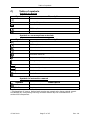
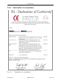
Instruction Manual SUPER GL speedy Valid for Version: 10.9 Effective from April, 2010 Manufacturer / Copyright: Dr. Müller Gerätebau GmbH Burgker Str. 133 D – 01705 Freital Distributor: Service – Hotline: Monday – Friday from 7 a.m. until 6 p.m. If you have any questions concerning our products or would like to place an order, please contact: +49 (0)351 649 12 93 +49 (0)351 64 50 42 Or contact us via: Fax: +49 (0)351 649 15 04 Email: [email protected] or [email protected] You will find the current version of this manual on our website www.glukose.de 15.04.2010 Page 1 of 45 Rev. 04 Table of contents A) Table of contents: Page 2 4 5 Rev. 03 05 02 A B C Table of contents Table of figures Table of symbols 1 1.1 1.2 1.2.1 1.2.2 1.2.3 1.2.4 1.3 1.4 1.5 Preface Introduction The SUPER GL speedy Basics Declaration of compliance Device and accessories Overview of functionality Indication / Contraindication Manufacturer's liability Warranty 6 6 6 7 8 9 9 10 10 10 02 02 02 03 02 02 02 02 02 02 2 2.1 2.2 2.3 2.4 2.5 Safety Introduction Responsibility / Training the operator General safety instructions Product-specific safety instructions Maintenance interval 11 11 11 11 12 12 02 02 02 02 02 02 3 3.1 3.2 3.3 3.4 3.5 3.6 Description of analyzer Introduction Intended use Measuring principle Layout and view Accessories Consumption material 13 13 13 14 16 16 17 02 02 02 02 02 02 02 4 4.1 4.2 4.3 4.4 4.5 4.5.1 4.5.2 4.6 4.6.1 4.6.2 4.6.3 4.6.4 4.6.5 4.6.6 4.7 Operation - Part 1 Introduction Safety instructions Installing the device Initial operation Preparing the measuring process Basics Sample preparation Measuring Rotor operation Chain operation Calibration Controls Method Printer settings Switching off the device 18 18 18 19 20 23 23 23 25 25 25 26 27 27 28 28 02 02 02 02 02 02 02 02 02 02 03 02 03 02 02 02 15.04.2010 Page 2 of 45 Rev. 04 Table of contents Page 29 29 29 29 29 29 29 31 31 31 31 32 32 32 33 33 34 34 34 35 Rev. 02 02 02 02 02 03 03 04 04 04 04 04 04 04 04 03 03 03 03 04 5 5.1 5.2 5.3 5.3.1 5.3.2 5.3.2.1 5.3.2.2 5.3.2.3 5.3.2.4 5.3.2.5 5.3.3 5.3.3.1 5.3.3.2 5.3.3.3 5.3.3.4 5.3.3.5 5.3.3.6 5.3.3 5.3.4 Operation - Part 2 Introduction Menu functions Programming Basics Method Adjust Select Print Programming Plasma reference glucose Functions Adjust Actions Read key card Service Barcode on / off User ID Measuring value memory Available cards 6 6.1 6.2 6.3 6.3.1 6.3.2 6.3.3 6.3.4 6.3.5 6.3.6 6.4 6.4.1 6.4.2 6.4.3 6.4.4 Maintenance and troubleshooting Introduction Maintenance Servicing Cleaning and disinfection Exchange of piston / cylinder system Exchange of canula and washing chamber Exchange of sensor Exchange of supply and waste container Switching off the device Error Messages / Troubleshooting Warnings Errors while measuring Mechanical errors Measuring errors 36 36 36 35 36 37 37 38 39 40 41 41 41 42 43 02 02 02 02 02 03 03 04 03 02 02 02 03 02 02 7 Technical data 45 03 15.04.2010 Page 3 of 45 Rev. 04 Table of figures B) Table of figures Overall view SUPER GL speedy Declaration of compliance View device Accessories Fig. Fig. Fig. Fig. 1.1 1.2 1.3 1.4 Page 6 8 9 9 Flow schema Diagram of measuring principle (only glucose) Diagram of measuring principle (glucose/lactate) Overall view SUPER GL speedy Accessories Fig. Fig. Fig. Fig. Fig. 3.1 3.2 3.3 3.4 3.4 14 14 15 16 16 02 02 02 02 02 Connections SUPER GL speedy Touch Screen Main program branches Sample preparation using open-end capillary Fig. Fig. Fig. Fig. 4.1 4.2 4.3 4.4 20 21 22 24 03 03 03 02 View washing container View sample canula Sensor holder closed Sensor holder open View supply and waste container Table of errors during measuring Fig. Fig. Fig. Fig. Fig. Fig. 6.1 6.2 6.3 6.4 6.5 6.6 37 37 38 38 39 40 04 04 04 04 03 03 List of technical data Fig. 7.1 34 02 15.04.2010 Page 4 of 45 Rev. 02 02 02 02 Rev. 04 Table of symbols C) Table of symbols Symbols on device Symbol Description Follow instruction manual In-vitro-Diagnostica IVD Manufacturer CE Compliance SN serial number Symbols on consumptions materials Symbol Description Diagnostic use in vitro IVD CE Compliance Note attached documents Follow instruction manual Reusable material Dispose according to regulations Storage temperature REF Item number Cont. Contents of package LOT Batch number Use before Symbols in instruction manual Symbol Description Attention or Note Bold/italics Very important notes * Explanation of terms: Authorized people are people who have gained expert knowledge by completing training courses offered by the manufacturer or authorized companies. 15.04.2010 Page 5 of 45 Rev. 04 Introduction 1 1.1 Preface Introduction Congratulations on purchasing the SUPER GL speedy analyser. We hope you will find working with your analyser satisfying and successful. In the following chapter "The SUPER GL speedy" you will find a first overview of your analyser: what parameters you can measure, what further devices and accessories belong to your analyser, and an overview of the device's functionality. Furthermore, you will receive information on safety, on liability and warranty, and on indications or contraindications of your analyser. For further and more detailed information, please read the corresponding chapters. 1.2 The SUPER GL speedy The SUPER GL speedy analyser is a device for biochemical analysis in invitro diagnostics. The device is an analyser for determination of glucose and / or lactate. Fig. 1.1 15.04.2010 Overall view SUPER GL speedy Page 6 of 45 Rev. 04 Introduction 1.2.1 Basics The SUPER GL speedy was designed using the latest technology along with decades of experience in the area of production of clinical-chemical analysers. It fulfils all legal specifications with regard to design and production that are required of all devices used in clinical chemical laboratories. The compliance with the valid norms and statutes is documented through the visibly attached CE-Label. The CE-Label signifies compliance with all pertaining laws and regulations and consequently safety and confidence. By employing an altogether newly developed technology for the determination of glucose and lactate, it is possible to fulfil all requirements of quality assurance (e.g. RiliBäk (Guidelines of the Federal General Medical Council for Quality Assurance in Medical Laboratories )) in medical laboratories while maintaining easy handling and minimum operating effort. All users are thus able to achieve analysis results that meet the quality demands. 15.04.2010 Page 7 of 45 Rev. 04 Introduction 1.2.2 Declaration of compliance Fig. 1.2 15.04.2010 Declaration of compliance Page 8 of 45 Rev. 04 Introduction 1.2.3 Device and accessories Deliverables: Designation Quantity SUPER GL speedy 1 Sample rotor 1 Power connection cable 1 Power supply adapter for device and printer 1 Printer DPU 414 1 Printer cable 1 Instruction manual 1 Optional EDP cable Other sample rotors 1 1 Fig. 1.3 View device 1.2.4 Fig. 1.4 Accessories Overview of functionality The SUPER GL speedy analyser is an automatic analyser for the determination of glucose and / or lactate in prediluted samples at a ratio of 1+50, i.e. in hemolysed blood samples. The device measures series up to 30 patient samples and has the possibility to measure a STAT sample very quick. The results of measurement will be showed at the Touch screen and will printed out or they could be sent to EDP. There is also the possibility to measure the samples with a barcode for a better management by EDP. For further information on measuring principle and sample taking, please refer to the appropriate chapters. 15.04.2010 Page 9 of 45 Rev. 04 Introduction 1.3 Indication / Contraindication Indication: The SUPER GL speedy analyser is used for measuring of glucose and / or lactate in human sample material. Suitable sample material: capillary or venous or arterial blood serum plasma cerebro-spinal fluid for more materials ask the manufacturer The sample may contain the following anticoagulants / glycolysis blockers: heparin, citrate, fluoride, EDTA. The SUPER GL speedy analyser must only be used and operated by trained personnel. Contraindication: Using unsuitable sample material can result in faulty measuring results. If in doubt, call the manufacturer! Operating the device for home testing is expressly forbidden! 1.4 Manufacturer's liability Legal liability and warranty claims are expressly excluded in the following cases: - gross negligence or wilful damage of the device, parts thereof or consumption material - unauthorized opening of the device by untrained personnel (without proper service training) - force majeure (e.g. stroke of lightning, water damage, fire) - nonobservance of user manual and package inserts 1.5 Warranty For their products Dr. Müller Gerätebau GmbH gives a two-year warranty according to EU Directive 1999/44/EG starting with the day of purchase. Consumption material (because of shorter shelf-life) and parts subject to wear (they should be replaced on a yearly basis) are expressly excluded from this warranty. For further information on spare parts and consumption material, please refer to the appropriate chapter. 15.04.2010 Page 10 of 45 Rev. 04 Safety 2 2.1 Safety Introduction The following chapters concern the safety of the person operating the device. Read these chapters carefully PRIOR to starting up the device because they contain general safety warnings, warnings concerning the personal safety of the person operating the device, and warnings for the protection of the device. Displaying the following safety warnings does not release the person operating the device from adhering to the safety measures of the facility. 2.2 - - - 2.3 - - - Responsibility / Training of the operator The SUPER GL speedy analyser must only be used and operated by trained personnel. An employee of the manufacturer or of an authorized distributor will introduce the operation of the device. Every user is responsible for adhering to safety, health and legal regulations, and operating the device only according to its intended use. Interpreting the results and diagnosing on that basis must be left to a medical practitioner. Operating the device for home testing is expressly forbidden. General safety instructions Prior to operating the device, read the entire instruction manual especially the instructions for sample taking. If you have any questions, please contact the manufacturer or authorized distributor. Every person working with the device must be acquainted with the relevant safety rules prior to operating the device and these rules should be kept at hand all the time. Please pay attention to all general safety rules for laboratories such as wearing protective gloves, and the applicable disinfection and hygiene regulations. 15.04.2010 Page 11 of 45 Rev. 04 Safety - To avoid risk of electric shock, do not place the device or power supply in water or other liquids! If the cable or the power supply adapter is damaged in any way, you must not continue using the power supply. Never touch the plug of the power supply adapter with wet hands. The power supply adapter must only be used indoors and must be protected from humidity. 2.4 Product-specific safety instructions - - - - - - 2.5 The device may only be used for the intended use with special attention to the defined usage restrictions and constraints that have to be strictly adhered to (if need be, contact the manufacturer). Operate the device only on smooth, horizontal surfaces. Avoid variations in temperature, drafts, direct sun light, and vibrations. These can result in faulty measuring values. In case of malfunctions, stop operating the device immediately! Prior to continuing to operate the device, read the notes concerning cleaning, error messages and troubleshooting. After consulting the manufacturer or authorized distributor you may ship the device for repairs to the manufacturer or authorized distributor. Use only original accessories and spare parts to avoid damage to device and people. Repairs must only be conducted by the manufacturer or by companies authorized by the manufacturer! The use of reagents and consumption materials that are not expressly recommended by the manufacturer can cause severe measuring errors and malfunctions and is therefore not permissible. If the user opens the device without authorization, the user shall not be entitled to any rights concerning the liability for the device and damages caused thereby. Maintenance intervals The SUPER GL speedy needs maintenance once a year by trained personnel. The touch screen will print out a message after expiration of the maintenance rate. Without regular maintenance, false measuring results can occur that are not the responsibility of the manufacturer. For further information, please refer to the chapter Maintenance / Troubleshooting. 15.04.2010 Page 12 of 45 Rev. 04 Description of the analyser 3 3.1 Description of analyser Introduction This chapter describes the analyser's measuring principle, layout, and accessories, and the consumption material. This chapter will provide you with forward information. For detailed instructions and descriptions of the device, please refer to chapter Operation. 3.2 Intended use The SUPER GL speedy analyser is an automatic analyzer for the determination of glucose and / or lactate in prediluted samples at a ratio of 1+50, i.e. in haemolysed blood samples. Suitable sample material: capillary or venous or arterial blood serum plasma cerebro-spinal fluid for more materials ask the manufacturer The sample may contain the following anticoagulants / glycolysis blockers: heparin, citrate, fluoride, EDTA. When using non-stabilized sample material, time between taking the sample and stabilizing it with glucose system solution should not exceed 15 minutes. The sample material is taken out of closed sample cups that are placed on a sample rotor. The containers for the washing and waste solution are located inside the device. Both containers must be replaced at the same time since they are adjusted to each other. The device has the following features: - Determination of glucose and / or lactate using the enzymaticamperometric measuring principle. - Automatic STAT sample measurement or sample series measurement up to 30 samples - automatic detecting the barcode - also for STAT - sample - automatic calibration before every series or STAT sample - serial printer interface - programmable EDP interface 15.04.2010 Page 13 of 45 Rev. 04 Description of the analyser 3.3 Measuring principle The determination of glucose with the SUPER GL speedy is based on an electro-chemical measuring principle with a biosensor. With the help of an analyser pump system solution, calibration solution, control material or patient’s material is conveyed through a sensor. The electrodes inside the sensor are separated from the liquid by sealing layers containing immobilized enzymes. The following figures show the flow schema and the reactions taking place inside the sensor: Fig. 3.1 Flow schema Fig. 3.2 Diagram of measuring principle (only glucose) 15.04.2010 Page 14 of 45 Rev. 04 Description of the analyser Fig. 3.3 Diagram of measuring principle (glucose / lactate) 15.04.2010 Page 15 of 45 Rev. 04 Description of the analyser 3.4 Layout and view View Fig. 3.4 Overall view SUPER GL speedy Fig. 3.5 Accessories Deliverables: Description Quantity SUPER GL speedy 1 Sample rotor 1 Power connection cable 1 Power supply adapter for device and printer 1 Printer DPU 414 1 Printer cable 1 Instruction manual 1 Optional EDP cable Other sample rotors 3.5 1 1 Accessories As described and shown above, the SUPER GL speedy comes with standard accessories. In addition, further optional accessories can be ordered. Both the manufacturer and the authorized distributors will gladly supply you with information about connecting interfaces. 15.04.2010 Page 16 of 45 Rev. 04 Description of the analyser 3.6 Consumption material To operate the analyser following consumption material is needed: - Prefilled sample cups without capillaries or with end-to-endcapillaries or with open-end-capillaries for taking the sample - calibration solution - bottles with haemolysed-system-solution - sensor glucose or sensor glucose / lactate - control material For detailed instructions on the use of these consumption materials, please refer to the chapter Operation of this manual. 15.04.2010 Page 17 of 45 Rev. 04 Operation - Part 1 4 4.1 Operation - Part 1 Introduction In this part of the instruction manual, all information is included that is useful for the day-to-day operation of the device. In part 2, all additional information is included that is important for understanding the functions, complementary functions and certain sources of possible problems. The qualified personnel for the device must be familiar with both parts and must also have the medical knowledge to be able to interpret the acquired values correctly. Conclusions for a therapy may only be drawn by a medical practitioner. 4.2 Safety instructions As mentioned before, certain safety warnings must be heeded when operating the device to guarantee correct and faultless operation: - - - - The device must only be used for the described indication and must only be used and operated by trained personnel. Every user is responsible for adhering to safety, health and legal regulations, and operating the device only according to its intended use. Interpreting the results and diagnosing on that basis must be left to a medical practitioner. Operating the device for home testing is expressly forbidden. In daily operation, regular checks of the results should be made; if needed, an additional control measurement should be carried out. Do not switch off the device or disconnect it from the power supply while it is running. If this happens, malfunctions can occur the next time the device is switched on. If you suspect a malfunction or faulty measuring results, please inform the person responsible for the device immediately. If necessary, this person will contact the manufacturer or distributer to solve the problem. 15.04.2010 Page 18 of 45 Rev. 04 Operation - Part 1 4.3 Installing the device Before start-up, check the supplied device and accessories for completeness referring to the list under 3.4. If anything is missing, please contact your supplier immediately. Furthermore, please check all parts for intactness. Proper and safe operation is only guaranteed when using original parts and accessories. NEVER use damaged parts or parts from other manufacturers! Place the device on a horizontal, smooth and dry surface. Please choose a location where the device is protected from direct sunlight and extreme variations in temperature since these can impair measuring results. Requirements on the set-up location - no direct humidity influence - no direct sunlight - no strong electromagnetic fields or ionizing radiation - no rapid changes in temperature because of windows, doors, airconditioning etc. - level, water-proof support - clearance over the entire footprint Connecting the device to the power supply: Please make sure that the voltage noted on the power adapter is the same as the voltage of your power grid. The device is connected to the power supply via the included power supply adapter. Connect the power supply cable to the power supply adapter. Plug one end of the power supply adapter into the power connector at the right side of the device (see fig. 4.1) and the other end into the socket. Connecting the printer: Please make sure that the voltage noted on the power adapter is the same as the voltage of your power grid. The printer is supplied with power via the second connection of the line cord. The jack of the printer cable is inserted into the printer interface on the right hand panel of the device's casing (s. fig. 4.1) and connected to the corresponding interface on the back panel of the printer. Connecting EDP (s. fig. 4.1): Plug the EDP cable into the EDP-port at the right side of the device and connect the other end with your EDP. Please pay attention to the notes in the manual for interfaces and also to the notes from your EDP partner. The jack of the printer cable is inserted into the printer interface on the right hand panel of the device's casing (s. fig. 4.1) and connected to the corresponding interface on the back panel of the printer. 15.04.2010 Page 19 of 45 Rev. 04 Operation - Part 1 The following image shows the interfaces on the right hand panel of the casing of the SUPER GL speedy: 1 2 3 1 2 3 power jack connection for printer connection for EDP Fig. 4.1 Connections SUPER GL speedy 4.4 Initial operation When the device was installed as described above, proceed as follows: - Exchange the sensor (chapter 6.3.4) Exchange the supply and waste containers (chapter 6.3.5) This procedure completes the installation of the device. Warning! To avoid loss of data, the device must not be switched off unless in “Stand-by” mode or if required by a corresponding error message. After switching on the device, it will enter Stand by mode after the necessary warm-up period. 15.04.2010 Page 20 of 45 Rev. 04 Operation - Part 1 The SUPER GL speedy is operated with the help of the Touch Screen only (cl. fig. farther down): Fig. 4.2 Touch Screen When operating the touch screen, please note: press only lightly do not use pointed or sharp objects do not use any solvents for cleaning, excepting the solution for cleaning and disinfection (chapter 6.3.1) Browse menus and set numerical values by touching the respective areas. Please note, that dark shaped areas describe the status “OFF” or “INACTIVE”, but light shaped areas describe the status “ON” or “ACTIVE”. While operating SUPER GL speedy you have to note, that there are some menu points / functions which you need for day-to-day operation and there are also some you only need in service cases. The functions of day-to-day operation you could use without any special identification and they are changeable. The service function only should used by special trained personnel because of it is protected by a keyword. ATTENTION: If there are not authorized contacts in protected areas the manufacturer assumes no liability for wrong measurement results! The following page shows the menu structure of SUPER GL speedy. If you’ve got more questions, please ask the manufacturer or your distribution partner. 15.04.2010 Page 21 of 45 Rev. 04 Operation - Part 1 Fig. 4.3 Main program branches 15.04.2010 Page 22 of 45 Rev. 04 Operation - Part 1 4.5 4.5.1 Preparing the measuring process Basics The SUPER GL speedy uses prefilled reagents. For each analysis a prefilled reaction cup is needed. For measuring with SUPER GL speedy you also have to use a biosensor, calibration cups and control material. The sample cups you have to put into the signed positions at the sample rotor and after that you can start to measure a series. 4.5.2 Sample preparation Please observe the instructions on the package insert of the reagent cups concerning sample preparation! The following notes complement the above notes and they are only valid if capillary blood is used as sample material: When drawing a capillary blood sample, do not compress the tissue. Compressing the tissue leads to a dilution of the blood sample with intracellular fluid and can thus lead to faulty results. For taking a capillary blood sample, use suitable lancets and, if necessary, circulation-enhancing measures (such as lotions and massaging the spot) to yield a sufficient sample amount. On the following page, taking capillary blood using open-end capillaries is described and shown. Proceed likewise with an end-to-end capillary. 15.04.2010 Page 23 of 45 Rev. 04 Operation - Part 1 Taking capillary blood from the earlobe or the finger pad and filling the capillary over both markings. Make sure, it is properly filled (sufficient amount of blood, no air bubbles, no drops of blood at the end of the capillary etc.) Carefully wipe off the outer surface of the capillary Break the capillary at the predetermined breaking point (predetermined breaking point is located in the middle between two markings) Insert the completely filled capillary into the prefilled sample cup Shake sample cup until the blood has completely left the capillary. Fig. 4.4 Sample preparation using open-end capillary 15.04.2010 Page 24 of 45 Rev. 04 Operation - Part 1 4.6 4.6.1 Measuring Rotor operation The SUPER GL speedy allows for measurements in two modes of operation. Determination of quick and control samples Determination of a sample series To start a sample series proceed as follows: Place sample cups on the sample plate. You do not have to start in position 1 and you may leave positions empty since the device possesses automatic sample cup recognition. In Stand-by mode press START on the TOUCH SCREEN. To measure a STAT sample: Press STAT on the TOUCH SCREEN in Stand-by mode or while measuring a sample series. To start a control sample series proceed as follows: Only the occupied control positions are measured, no samples. Press the following areas on the TOUCH SCREEN in Stand-by mode: MENU CONTROLS MEASURING Prior to each of these measuring regimes, a calibration is carried out unless a different calibration option was chosen. Other calibration options are enabled and explained by service personnel upon customer request. 4.6.2 Chain operation The determination of quick and control samples is carried out as described in 4.6.1. To start a sample series proceed as follows (see 5.3.2.1): Switch on chain operation (Methods / Adjust / Count). Place sample cups on the sample plate. Chain operation is characterized by stopping the series at the first unoccupied position. You then have three ways to continue measuring samples: „Sample“ button Measuring of the series is continued at the position flashing in the “Sample” area. „New plate“ button Measuring of the series is continued at position 1 on the plate. The counting of the sequential numbers (numbers within the series) is continued with the next higher sequential number. „New series“ button Measuring of the series is continued at position 1 on the plate. Counting of the sequential numbers is restarted with number 1. 15.04.2010 Page 25 of 45 Rev. 04 Operation - Part 1 To measure a quick sample, press STAT on the TOUCH SCREEN in Standby mode or while measuring a sample series. To start a control sample series, i.e. only the occupied control positions are measured - no samples - successively press the following areas on the TOUCH SCREEN in Stand-by mode: MENU CONTROLS MEASURING Chain operation is only recommended with an auto-calibration type. For more information see chapter 4.6.3. Explanation to measuring value memory: By choosing this menu item the measured rotor series will be shown. By choosing the menu item “values” the single values of the dark shaped rotor batch will be shown. Printing out and sending values to EDP are also possible in this mode: either the dark shaped batch or the dark shaped value. Explanation to control value memory: By choosing this menu item the measured controls will be shown. By pressing the button “Ko1/Ko2/Ko3” you will see the values for control 1, 2 or 3 or you will print them out. It will be printed the values from the dark shaped are up to the actual control value every time. 4.6.3 Calibration To guarantee correct measuring results the SUPER GL 2 needs a valid calibration. So the device calibrates for each option of measurement automatically. To customer request our service will activate also other calibration options. In this case following areas are available By pressing menu item “Calibration”: Auto calibration (activated upon customer request): Activates auto calibration mode. If the button is highlighted after touching, auto calibration is active. In Stand-by the period of time until the next calibration is displayed. Calibration takes place cyclically in the selected intervals. In addition the “Cal off” button is displayed. Touching this button deactivates auto calibration. 15.04.2010 Page 26 of 45 Rev. 04 Operation - Part 1 Calibration stable (activated upon customer request): This works just like auto calibration except that the next cyclic calibration is executed only when measuring is requested. Start calibration Executes a calibration. If Auto calibration is activated in the menu “Functions” - “Adjust” a new area “auto calibration” will be shown. If you choose “ON” the new started device starts after the warming time the calibration automatically and remains in the statues “auto calibration”. ADVICE: After switching on the device will calibrate every time before sample measurement for the first two hours. 4.6.4 Controls The SUPER GL speedy has three requirements of quality control. control positions to meet the To guarantee an effective quality control all three positions can be programmed. Following input options are programmable for each parameter: Name of the control lower warning limit for glucose upper warning limit for glucose lower warning limit for lactate upper warning limit for lactate For all three control positions the values stored can be displayed. 4.6.5 Method In device alternatives Glucose / Lactate following settings are possible: Glucose Lactate Glucose and Lactate 15.04.2010 Page 27 of 45 Rev. 04 Operation - Part 1 4.6.6 Printer settings The intended printer DPU 414 has several interface options. Follow these steps for setting / programming the printer for use with SUPER GL SPEEDY: 1. Keep the “on Line” button pressed whole switching on the printer. You will receive a print out of the current settings. 2. Press “On Line” again to reprogram the printer. 3. Press “On Line” for “ON” and “Feed” for “OFF” 4. Press “Feed” at the end of the programming to confirm. The following settings are required for SUPER GL SPEEDY: Position 1 2 3 4 5 6 7 8 4.7 SW1 OFF ON ON OFF ON OFF ON ON SW2 ON ON OFF ON ON ON ON OFF SW3 ON ON ON ON ON OFF ON OFF Switching off the device You may switch off the device, if there are no functions working. NEVER switch off the device during calibration or washing, otherwise the device may have malfunctions. If the device is switched off for a longer time (i.e. during the vacation) you have to rinse and to empty the device to avoid drying the hoses. Please store also the consumables (i.e. sensors and calibration solution) as written at the package. For more questions please don’t hesitate to contact us. 15.04.2010 Page 28 of 45 Rev. 04 Operation - Part 2 5 5.1 Operation - Part 2 Introduction This part of the instruction manual describes special functions and settings relevant to the user. Furthermore, it gives additional information about quality control and some problems that can be solved by the user. 5.2 Menu functions As described in chapter 4, there are two types of device functions: functions which are needed for day-to-day operation and functions which are only should be used by trained stuff. For working with following functions you need besides special knowledge also exact knowledge about the menu structure of the SUPER GL SPEEDY. The overview of the menu structure you find in fig. 4.3. 5.3 5.3.1 Programming Basics The programming of controls, calibration versions and printer settings are described in chapter 4. Following functions influence measuring results and their displaying and should only be activated by trained stuff (maybe by calling the service). 5.3.2 Method 5.3.2.1 Adjust The following settings can be made here: Measuring cycle: Here you can select in which position of the series control measurements or recalibration take place. A cycle consists of a maximum of 8 segments. The „Back“ button deletes the last segment. The sample type is added by touching the button. In chain operation mode the cycle is executed until for the first time a sample is selected. Afterwards only samples are processed. 15.04.2010 Page 29 of 45 Rev. 04 Operation - Part 2 Sample repetition This function interacts with the “sample warning limits”. To select an item, touch the button. Highlighted buttons are active. Counting Here you can choose between a sequential number and a sample number of the day. Chain operation is intended for users needing devices with sample chains (see also 4.6.2). To switch chain operation on/off, select the menu item Chain operation. Two buttons (On, Off) are displayed. Touch the appropriate button. The active button is highlighted. Reset parameters This function resets the programmed parameters and the device returns into the delivery status. This function should be used for plant hires to erase the customer specific settings. In detail it happens as follows: Sample number get number “1” Time gets EU Standard Year gets 4 digits Language changed to German Measuring unit gets mg/dl Sample repetition gets status “OFF” Sample number of the day gets status “OFF” Calibration modus gets status “inactive” (device calibrates before each series and before each STAT) Time of calibration stability gets 20 min Time of auto calibration gets 30 min Upper and lower warning limits of controls will be set to range limits Sample warning limits will be set to range limits Correction factor for methods gets standard values Chain operation gets status “OFF” Cycle gets standard value Measuring value memory and control value memory were erased Reset sample number This function sets the actual sample number (number of the sequence or daily number) to number 1 15.04.2010 Page 30 of 45 Rev. 04 Operation - Part 2 5.3.2.2 Select This menue item is only available in version glucose / lactate. Here you can select the parameter which you want to measure, i.e. glucose or lactate as single parameter or both simultaneous from one sample. 5.3.2.3 Print Prints out the parameter list. 5.3.2.4 Programming Measuring unit You can choose between mmol/l and mg/dl. Warning limits Enter a lower and an upper warning limit. For samples found outside these limits, an automatic repetition of the measurement can be programmed. Correction of measuring value This function offers a (separated for glucose and lactate if necessary) correction function with the equation y = mx + n to adapt this device to a giant laboratory equipment, if it’s necessary. 5.3.2.5 Plasmareference glucose Using this function you are able to manipulate the glucose values. Using „Plasmaref. Glucose off“ the glucose values, which came from blood samples will be calculated as blood sample values. Using „Plasmaref Glucose on“ the instrument will determinate the haematocrit values if the sample is a blood sample. Both values will be used to calculate the blood value into a plasma value. In this case will be printed out „Glucose-Haemolysate Samples plasmaref.“ when the instrument starts a series or when it measures controls or STAT- samples. 15.04.2010 Page 31 of 45 Rev. 04 Operation - Part 2 5.3.3 Functions 5.3.3.1 Adjust Time Setting of the time in form HH:MM Set date A changing of the date normally isn’t possible. Dialog language Currently are following dialog languages possible: German, English, Czech and Russian. More languages are possible after request. In this menu you also can choose the printing form of date and time. EDP interface parameters Enables configuration of the EDP interface. This should only be done with competent consultation. 5.3.3.2 Actions Rinsing of the system By the help of a pump solution will be pumped through the system from the suction hose in a defined time. This can be system solution or another solution, i.e. for disinfection. In this case the sensor will be destroyed. Emptying By the help of the pump the system will be emptied. In this case the suction hose should be outside the bottle with system solution. Changing allotment device (see “maintenance”) Moves the plunger in a position for changing Display sensor Shows the currently programmed data of the sensor. In the display are shown following data: Sensor Super GL ok Samples: xxxx Days xx Method (example) 3 / 5 / 14 / 3 / 12 The digits means in the sequence: method number, optional reinforcing glucose, maximum reinforcing glucose, optional reinforcing lactate, maximum reinforcing lactate Expiry Life time Activation 15.04.2010 Month/Year Month Date Page 32 of 45 Rev. 04 Operation - Part 2 Display supplies In the display are shown following data: Supplies SUPER GL ok Cups Buffer Samples Maintenance Maintenance samples XXXX XXXX ml XXXXXX XX.XX.XX XXXXXXX (samples until next maintenance) Adjust bubble detector Diode Empf. xxx Diff. Schw. xxx By touching the key „Repeat“ an automatically incident for new adjusting the sensitivity starts. After this incident the display shows: Diode XXX Empf. XX Diff. XXX Schw. xxx and a additional button “Save”. If there is a big difference between the data of the both upper lines, we recommend repeating this incident. With the button “Save” the actual values will be saved to adjust the bubble detector in the best way. 5.3.3.3 Read key card Enables you to read the inserted key card. Supplies of system solution and/or sample cups are electronically stored on the key card. The key card thus guarantees the operation of the entire system (device and consumption materials) to insure the analysis quality. A key card is included with every package of haemolysing system solution or pre-filled sample cups. By reading the key card, the supply of haemolysing system solution or pre-filled sample cups within the device is increased. When the supply is exhausted, the device reports "Please read key card". To read the key card, insert it into the reading device on the front panel. 5.3.3.4 Service For trained service personnel only. Description is in the service manual. 15.04.2010 Page 33 of 45 Rev. 04 Operation - Part 2 5.3.3.5 Barcode on/off This function determines – separately for control, quick and normal samples – whether the bar codes on the cups are read or not. To switch, touch the button. - Button dark - Button light = = bar code is not read bar code is read Note: The bar code reader is always active since it also serves to recognize occupied positions on the sample plate. If you want to use the bar code scanner to identify samples, please note the following: max. bar code length: 12 characters attach the bar code label to the marking on the sample cup the bar codes must be facing to the outside of the sample plate the device’s operation is limited productivity-wise if sample cups without bar code labels are used while the bar code scanner is active. Note: It is possible to improve the readability of particular bar codes by special configuration. In this case please contact the manufacturer or service. 5.3.3.6 User ID Enter a number for the operator using the device. 5.3.4 Measuring value memory The measuring value memory is a ring buffer. The most recent measuring values (approx. 500 values for one method by only using glucose; 250 values each by using both methods simultaneous) are stored. As soon as the buffer is full, the oldest values are deleted. The measuring value memory can be deleted manually. The stored values can be displayed sent repeatedly to the EDP printed repeatedly erased 15.04.2010 Page 34 of 45 Rev. 04 Operation - Part 2 The Button “detect coefficient of variation (COV)” calculate the mean value and the CV of the last measured series. To see the measuring value memory there are two display levels. In the level displayed first, all rows start with a „T“. A „T“ stands for a plate, i.e. every row can contain a maximum of 60 samples. Use the arrow to select a plate. If you press the „Print“ button, the results of the plate marked in black are printed. Sending data to the EDP works correspondingly. If you press the „Value“ button, the results of the plate marked in black are displayed. Now the values marked in black can be printed or sent. 5.3.4 Available cards Key card Key cards are supplied with packages of haemolysing system solution and pre-filled sample cups. They are used to read the supplies. Other cards More cards, i.e. for changing the language etc. you get from the manufacturer or your distributor. 15.04.2010 Page 35 of 45 Rev. 04 Maintenance and troubleshooting 6 6.1 Maintenance and troubleshooting Introduction This chapter gives information on maintenance of the SUPER GL speedy and about problems that may occur and how you might be able to solve them yourself. If you are unsure about certain aspects, DO NOT try anything you might think appropriate without qualified technical help. DO NOT open the device without an authorized service technician*! Please contact our service hotline free of charge! 6.2 Maintenance The SUPER GL speedy needs maintenance once a year by trained personnel. The touch screen will print out a message after expiration of the maintenance rate. Please contact the manufacturer or distributor immediately to make an appointment for service. 6.3 Servicing The following operations can and should be carried out by the operator. These actions are part of diligent care and serve to enhance the device's life span. They are NOT maintenance or service work, these may only be carried out by authorized service personnel*! 6.3.1 Cleaning and disinfection Please adhere to the regulations valid in your laboratory with regard to cleaning and disinfecting the device. For disinfection wipe the entire accessible surface of the device with a cloth containing disinfectant. Use a disinfectant for surface disinfection! Also note the instructions of the manufacturer of the disinfectant. 15.04.2010 Page 36 of 45 Rev. 04 Maintenance and troubleshooting 6.3.2 Exchange of piston / cylinder system For changing the piston / cylinder system proceed as follows the in the order specified: Choose at the touch screen: menu -> functions -> actions -> change dosage The plunger moves into a position for changing. Turn off the device Open the device’s back panel Screw off the piston/cylinder system from the valve block Remove piston/cylinder system by folding outside and pulling off To install the piston/cylinder system, follow the instructions in reverse order Secure back panel 6.3.3 Exchange of canula and washing container 2 1 fig. 6.1 View washing container fig. 6.2 View sample canula Removal 1. Turn off the device 2. Remove the hose of the supply bottle 3. Place this hose in a little container or some cellulose at the table (maybe there is some liquid left inside of the hose) 4. Remove the hose (1) 5. Loosen the screw (2) 6. Remove needle 7. Remove washing container from the holding-down fitting by pushing it backwards and lifting upwards. 15.04.2010 Page 37 of 45 Rev. 04 Maintenance and troubleshooting Installation 1. Insert washing container into the holding-down fitting 2. Insert sample canula 3. Connect hose to the washing container 4. Insert the hose of the supply into the supply container 6.3.4 Exchange of sensor Removal of Sensor Open the sensor holder by pulling the lever fig. 6.3 Sensor holder closed Remove the sensor fig. 6.4 Sensor holder open 15.04.2010 Page 38 of 45 Rev. 04 Maintenance and troubleshooting Installation of Sensor 1. 2. 3. 4. Open the packaging and take out the sensor Open the sensor holder by pulling the lever (3) (fig. 7.8) Insert sensor Close the sensor holder 6.3.5 Exchange of supply and waste container To avoid interference with the operation of the device, it is recommended to exchange the containers only in „stand-by“ mode and when the washing container and the sample canula are installed. The changing of these bottles should be done in a short time, because of washing the system there will be a little bit solution left from time to time. Furthermore, the supply container that was last emptied should be used as a waste container because the repeated use of containers could affect the function of the level sensor. fig. 6.5 view of supply and waste container Removal of Supply- and Waste Container 1. Open the device cover 2. Remove the canula 3. Remove the containers (supply left, waste right) Insertion of Supply- and Waste Container 1. If necessary, open the device cover 2. Insert the containers (supply left, waste right) 3. Open the containers and insert the canula 4. Close the device cover 15.04.2010 Page 39 of 45 Rev. 04 Maintenance and troubleshooting 6.3.6 Switching of the device To switch off the device for a longer period of time or for transport, proceed as follows: 1. Rinse the device 2. Empty the system by removing the hose from the supply bottle and push the bottom “Emptying”. 3. Switch off the device and disconnect. Please store all consumables as written at the packages. Disposing of the device: For the disposal of devices manufactured after April 2006, customers in Germany should contact the manufacturer. 15.04.2010 Page 40 of 45 Rev. 04 Maintenance and troubleshooting 6.4 6.4.1 Error messages / Troubleshooting Warnings Before printing the measured results, the device checks whether set warning limits have been exceeded. The sample warning limits (chapter 5) are relevant for the determination of patients’ samples, control limits (chapter 5) are relevant for the determination of control samples. The following warning are displayed and printed: Warning ++++ !! Explanation Values above measuring range limit Values below measuring range limit Below or above the sample warning or control limits Previous control measurement outside the control limits and below or above the sample warning ! 6.4.2 Errors while measuring Measuring value defective (only version glucose) Measuring signal is loaded with an interference signal which is more than 70 % of the measuring signal. The interference signal is compensated, but measuring value is less precise than a non disturbed signal. Measuring value defective (both correction value for plasma measuring is not versions) plausible, repeat measuring Zero line instable - appears incidentally -> repeat incident - changing reagent -> choose “Washing” - system obstructed -> rinsing by hand - Sensor defective -> change sensor - electronic error -> call service Zero comp instable Analogue to error „zero line instable”, but for the (only version glucose) compensation channel Calibration value to low - choosing wrong cup - Sensor defective -> change sensor - electronic error -> call service Calibration drift to high - Appears incidentally -> calibrate new - Rapid change of temperature -> calibrate new - System obstructed -> rinsing by hand - Sensor defective -> change sensor - Electronic error -> call service Error sample - System obstructed -> rinsing by hand - Connection hose sample canula – sensor heavy discoloured - Sample canula maladjusted (defective) Sample cup empty Remaining quantity in the sample cup is not enough for a measurement fig. 6.6 Table of errors during the measuring 15.04.2010 Page 41 of 45 Rev. 04 Wartung und Fehlerbehebung 6.4.3 Mechanical errors If there are the following errors displayed the operator can’t do anything without the help of the service personal. The displaying is only for the service, to describe more exactly the errors. Type of errors Communication error ERROR (name of the component) no Ackn (no quittance of command) Handler doesn’t send a quittance of command ERROR (name of the component) Timeout Error of device / light barrier ERROR (name of the component) light barrier doesn’t open Handler doesn’t reach end position ERROR (name of the component) ERROR (name of the component) 3 tries 3 tries reference run Problem of communication between controlling computers ERROR (name of the component) device not available Wrong parameter in the memory ERROR (name of the component) Parameter-Flash Hardware and Software don’t fit together ERROR (name of the component) Hardware version Plunger doesn’t reach the dependent end position ERROR plunger type of error in clear text Error lifter ERROR lifter can’t prick Intern memory errors ERROR Fe-RAM 1 (name of error) There can be more similar messages of errors which are printed out to the same schema. 15.04.2010 Page 42 of 45 Rev. 04 Maintenance and troubleshooting 6.4.4 Measuring Errors Glucose and lactate are determined using the enzymatic-amperometric measuring principle. The measuring signal is produced as a current change at an electrode due to a chemical reaction with the immobilized enzyme. In the SUPER GL speedy a special measuring process is used that operates with a minimum amount of sample material. The hose between canula and sensor is critical for the proper functioning of this process. Therefore, this hose must only be replaced by an original spare part. You can visually check proper operation by watching the air bubbles between sample and washing. Version glucose: The air bubble that is drawn before a sample has to pass the sensor completely before sample will be measured. The air bubble that is drawn after measuring the sample has to stop and stay for a while in front of the sensor. Version glucose / lactate: The air bubble that is drawn before a sample has to stop in front of the sensor until the sample taking arm has returned to the upward position. The air bubble that is drawn after a sample has to stop in front of the sensor for a while. As with all flow systems, unobstructed flow through and imperviousness of the canal between the sample canula and the hose pump is very important for the proper functioning of the device. Always keep in mind that the hose pump works as a suction pump and that it produces a low pressure in the system. Leaking liquid is always a sign of permeability, e.g. worn seals of the washing container, loose hoses or an incorrectly inserted sample canula. Check for unobstructed flow and leakage: Switch off the device and switch it back on after 2 seconds. Thereby making sure that the pump is working. Make sure that the pump is turning. Uncover the waste bottle and watch whether liquid drops in regular intervals. If it does, there is no problem in the flow system. If no liquid is dropping out, the system is either leaky or obstructed. In this case proceed as follows: 15.04.2010 Page 43 of 45 Rev. 04 Maintenance and troubleshooting Remove the hose from the suction side of the hose pump and put a matching injection syringe onto the hose. With the syringe, suck liquid out of the supply bottle. Watch the liquid in the hose between sample canula and sensor. There are three possible reactions: The syringe can easily be moved, there are many air bubbles or only air in the hose. That means the system is leaking. The easiest way to find the leak is to look where the air bubbles occur. Check all connections and if necessary exchange the hoses and the washing container. The syringe can hardly be moved and the liquid in the hose barely moves. That means the system is obstructed. Loosen the hose from the washing container and attach it to the provided connector. Loosen the screw of the sample canula and pull the canula out of the washing container. Place the sample canula in a glass. Fill the syringe with distilled water or system solution and press the water from the hose toward the sample canula. The liquid should come out of the canula. If it does not, clean the canula with a cleaning wire and / or exchange the sensor. The syringe can be moved evenly but with resistance and the liquid flows back and forth inside the hose. In this case the error of the device is inside the housing and the device needs to be serviced. With these simple measures most problems in the flow system can be solved. The problems can result in the following: Scattering measuring values Could also be a result of incorrect sample preparation. Check by measuring a standard cup several times. A defect sensor could also be the cause. Calibration is not stable, drift too high Could be caused by extreme temperature variations (e.g. direct sun) Calibration not possible, value too low A defective (insensitive) sensor could also be the cause. Frequent occurrence of the error “margin maximum“ 15.04.2010 Page 44 of 45 Rev. 04 Technical data 7 Technical data Measuring time per sample Single sample Series (only glucose) Series (glucose / lactate) 45 sec. approx. 20 sec. approx. 20 sec. Measuring range Glucose Lactate 0,8 – 50 mmol/l (11 – 910 mg/dl) 0,5 – 30 mmol/l (4,5 – 270 mg/dl) Amount of sample material 10 / 20 µl sample diluted with 500 / 1000 µl heamolysate-system-solution Precision (20 samples) Glucose (216 mg/dl) Lactate (90 mg/dl) < 1,5 % < 2,0 % Storage period of sensor Storage temperature of sensor Life time of sensor 12 month + 2 °C up to + 8° C 1 month (guarantee), 2 months poss. Interfaces Printer EDP V 24 V 24 Operation temperature Storage temperature (without sensor) + 15 °C up to + 35 °C - 10 °C up to + 50 °C Supply voltage 12 V DC Power consumption Approx. 12 W Classification according MPG In-vitro-Diagnostic Dimensions (W x H x D) 365mm x 435mm x 250mm Weight Approx. 9 kg Manufacturer Dr. Müller Gerätebau GmbH Burgker Str. 133 01705 Freital Fig. 7.1 List of Technical data 15.04.2010 Page 45 of 45 Rev. 04