1
ABL90 FLEX operator’s manual
ABL90 FLEX
operator’s
manual
What is new in this manual?
•
The calibration verification procedure has been updated.
•
The section about how to clean the sensor cassette seat has been removed.
Operator’s manual
Note to the operators of the ABL90 FLEX analyzer
Introduction
This note outlines the improvements in software version 2.8.
Instructions to
operators
Put the Note to the operators in the binder of your manual and replace the
corresponding old front and date of issue pages with the new pages in this update kit.
Brief overview
of the
Improvements
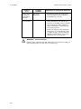
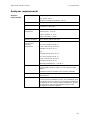
Improvements/Description
Storage temperature
for the sensor cassette
In the manual, the storage temperature of the sensor
cassette is incorrectly stated to be 2-10 °C.
The correct storage temperature of the sensor cassette is
2-8 °C.
Vocal reminder to close
the inlet
If the inlet is not closed, a voice message reminds you to do
so.
Video instructions of
the measuring
workflow
Video instructions have replaced most of the animations that
were previously shown on the screen.
More maintenance
instructions included in
the guided
troubleshooting of the
analyzer
Videos and text instructions have been added to the tasks to
maintain and replace the Inlet, the Inlet Probe, the Inlet
Gasket Holder and the Inlet Connector Gasket.
How values that lie
outside the reportable
ranges are shown
In software versions up to and including 2.7, results that are
outside the reportable ranges of the analyzer are shown
without values on the Patient result screen and in printed
results and no values are transmitted to connected LIS/HIS
systems.
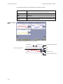
When the Troubleshooting needed screen is shown, follow
the instructions on the screen. The analyzer will then guide
you through the procedures.
This is still the default setting, but in SW version 2.8 it is
possible to get the exceeded range limit of the reportable
range shown in the value field. If e.g. the result is below the
value, which is the lower limit of the reportable range, the
result is shown as “<range”.
The contents of this document will be added to the manual the next time the manual is
updated.
Radiometer Medical ApS
Åkandevej 21
2700 Brønshøj
Denmark
www.radiometer.com
©2012 Radiometer Medical ApS. All Rights Reserved. 995-417. 201207A.
Operator’s manual
Note to the users of the ABL90 FLEX analyzer
Introduction
Instructions to
user
This note outlines the improvements in software version 2.7.
•
Videos and text instructions will guide you through various troubleshooting
procedures to solve fluid transport problems.
•
Under Consumables in the Analyzer status screen, replacement data about
the Inlet Gasket Holder is shown instead of replacement data about the printer
paper.
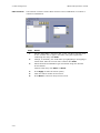
Put this document in the binder of your manual.
The TroubleWhen the Troubleshooting needed screen appears, follow the instructions on the
shooting needed screen.
screen
The analyzer guides you through each troubleshooting procedure. After each procedure
the analyzer checks to see if the problem has been solved.
If the troubleshooting procedures do not solve the problem, the analyzer enters the
Operator-intervention required screen.
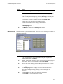
To replace the
Inlet Gasket
Holder
1. Log on.
2. Tap Menu > Analyzer status > Consumables > Replace > Replace the inlet
gasket.
3. Follow the instructions on the screen.
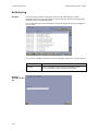
To see details
about the Inlet
Gasket Holder
1. Log on.
2. Tap Menu > Analyzer Status > Consumables > Status > Gasket status.
Standardizing
These terms have been changed in the software:
the terminology
Term
Changed to…
of the software
User
Operator
Replacements
Consumables
Replace solutions
Replace Solution pack
Instrument
Analyzer
The terms will be added to the manual the next time the manual is updated.
The contents of this document will be added to the manual the next time the manual is
updated.
Operator’s manual
Note to the users of the ABL90 FLEX analyzer
Introduction
From software version 2.6.2132.11, a clot detection and removal process has been
added.
Instructions to
user
Please put this document in the binder of your manual.
Clot detection
and removal
process
For preventive action, the analyzer checks for clots during blood sample measurements
and, once a day, also during the system check started at midnight.
If there is a sign of a clot in the analyzer during checks, the following occurs:
1.
There is a clot-related error message in the Activity log.
2.
The analyzer aborts the current action.
3.
The analyzer goes into the Cleaning mode.
4.
The analyzer starts the clot removal process.
5.
The analyzer starts a system check if the clot was found during the system check
at midnight.
6.
• If the analyzer has removed the clot, the analyzer goes into the Ready mode.
• If the clot is still there, the analyzer goes into the Intervention Required mode.
Follow the on-screen instructions to remedy the error or see the ABL90 FLEX
operator's manual for further information about the Intervention Required mode.
Technical
documentation
Data in this document will be added to the manual the next time the manual is updated.
Operator’s manual
Note to the users of the ABL90 FLEX analyzer
Introduction
This note to users describes the battery feature of the ABL90 FLEX analyzer.
Instructions to
user
Please place this document in the binder of your manual.
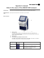
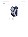
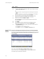
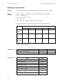
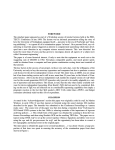
Brief overview
1
Battery pack
The battery pack enables, for a limited period of time, the performance of
measurements and the storage of data without the analyzer being connected to
mains or during power failure.
2
Battery LED
3
The battery level indicator on the screen
The battery level indicator on the screen is only visible if the battery is installed.
The battery charge level is indicated by a percentage.
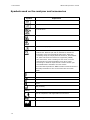
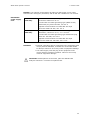
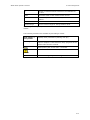
Battery LED
Constantly green
Battery level
indicator
Indication
The analyzer is connected to mains.
The battery is fully charged (100 %).
Blinking green
The analyzer is connected to mains.
The battery is charging.
Blinking yellow
steadily
The analyzer is running on battery.
If battery charge level: ≤25 %.
− A system message is shown in the Activity
log.
− The battery charge level in the icon of the
battery level indicator is yellow.
Corrective action:
− Connect the analyzer to mains.
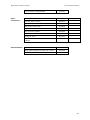
Blinking intense
yellow
The analyzer is running on battery.
If battery charge level: ≤13 %.
− A message is shown on the screen.
− The battery charge level in the icon of the
battery level indicator is red.
Corrective actions:
− Connect the analyzer to mains.
− Close the dialogue box.
If battery charge level: ≤10 %, the analyzer automatically performs a controlled
shutdown.
Corrective actions:
− Connect the analyzer to mains.
− Turn on the analyzer.
Battery specifications:
Technical
documentation
Battery operation
Approximately 1 hour of battery power when analyzer is in
Ready mode, or approximately 25 samples.
Battery pack charge
time
Approximately 90 minutes to fully charge a depleted battery
pack.
Data in this document will be added to the manual next time it is updated.
Radiometer Medical ApS
Åkandevej 21
2700 Brønshøj
Denmark
www.radiometer.com
Table of contents
ABL90 FLEX
Operator's
manual
From software version 2.8xx
1.
Introduction
2.
What is what
3.
Analyzer status
4.
Sample measurements
5.
Quality management
6.
Calibration
7.
Replacements
8.
Disk functions
9.
Data management
10. Analyzer shutdown
11. Troubleshooting
12. Sampling
13. Specifications
14. Ordering information
Index
Date of issue
System performance
The procedures described in this manual must be observed in order to ensure proper system
performance, and to avoid hazards.
Radiometer cannot provide or verify system performance characteristics if the system is not installed,
used and maintained in accordance with Radiometer procedures or if accessories not meeting the
specifications provided by Radiometer are used.
Radiometer warrants that the data media on which the software included in the system is furnished is
free from defects in material and workmanship under normal use for three (3) months from the date
of delivery as evidenced by a copy of invoice or receipt.
Third-party software and trademarks
The ABL90 FLEX analyzer comprises the Microsoft® Windows®XP Embedded and Sybase® SQL
Anywhere® software.
By using the system, you accept the terms of the Software License Agreement(s) of the provider(s)
of the above software as shown in the End User License Agreement(s) included in this manual. If you
cannot accept the terms of the Software License Agreement(s), you should not use the system, but
immediately contact your provider for a return of the system and a refund of the purchase price.
Microsoft® and Windows® are trademarks of Microsoft Corporation. Sybase® SQL Anywhere® is a
trademark of Sybase Incorporated.
Warranties and disclaimer
Radiometer makes no warranties, express or implied, other than expressly stated.
Any warranties expressly stated in this document are conditional upon the system being installed,
used and maintained in accordance with Radiometer procedures, including that only accessories
meeting the specifications provided by Radiometer are used.
Radiometer disclaims any liability for system performance if the system is not installed, used and
maintained in accordance with Radiometer procedures or if accessories not meeting the specifications
provided by Radiometer are used.
Further, Radiometer disclaims any liability for loss of data and direct, consequential or other damages, including loss of profit or loss of business, whether such claim for damages is based upon
contract, negligence or tort (including strict liability), and even if Radiometer has knowledge of the
possibility of the potential damage or loss.
Confidentiality
The contents of this document shall not be reproduced or communicated to any third party without
the prior written consent of Radiometer.
Changes
This document is subject to change without notice.
While every effort is made to ensure the correctness of the information provided in this document as
changed from time to time, Radiometer disclaims any liability for errors and omissions.
Radiometer, the Radiometer logo, ABL, AQT, TCM, RADIANCE, AQURE, PICO, CLINITUBES and QUALICHECK are trademarks of or
used under license by Radiometer Medical ApS.
© 2013 Radiometer Medical ApS. All rights reserved.
End-user license agreement for the ABL90 FLEX analyzer
You have acquired a device ("DEVICE") THAT INCLUDES SOFTWARE LICENSED BY Radiometer
Medical ApS from Microsoft Licensing Inc. or its affiliates ("MS"). Those installed software products
of MS origin, as well as associated media, printed materials, and "online" or electronic
documentation ("SOFTWARE") are protected by international intellectual property laws and
treaties. The SOFTWARE is licensed, not sold. All rights reserved.
IF YOU DO NOT AGREE TO THIS END USER LICENSE AGREEMENT ("EULA"), DO NOT USE THE
DEVICE OR COPY THE SOFTWARE. INSTEAD, PROMPTLY CONTACT THE SUPPLIER OF THE
INSTRUMENT FOR INSTRUCTIONS ON RETURN OF THE UNUSED DEVICE(S) FOR A REFUND. ANY
USE OF THE SOFTWARE, INCLUDING BUT NOT LIMITED TO USE ON THE DEVICE WILL
CONSTITUTE YOUR AGREEMENT TO THIS EULA (OR RATIFICATION OF ANY PREVIOUS
CONSENT).
GRANT OF SOFTWARE LICENSE. This EULA grants you the following license:
•
You may use the SOFTWARE only on the DEVICE.
•
NOT FAULT TOLERANT. THE SOFTWARE IS NOT FAULT TOLERANT. RADIOMETER MEDICAL
ApS HAS INDEPENDENTLY DETERMINED HOW TO USE THE SOFTWARE IN THE DEVICE, AND
MS HAS RELIED UPON RADIOMETER MEDICAL ApS TO CONDUCT SUFFICIENT TESTING TO
DETERMINE THAT THE SOFTWARE IS SUITABLE FOR SUCH USE.
•
NO WARRANTIES FOR THE SOFTWARE. THE SOFTWARE is provided "AS IS" and with all
faults. THE ENTIRE RISK AS TO SATISFACTORY QUALITY, PERFORMANCE, ACCURACY,
AND EFFORT (INCLUDING LACK OF NEGLIGENCE) IS WITH YOU. ALSO, THERE IS NO
WARRANTY AGAINST INTERFERENCE WITH YOUR ENJOYMENT OF THE SOFTWARE OR
AGAINST INFRINGEMENT. IF YOU HAVE RECEIVED ANY WARRANTIES REGARDING THE
DEVICE OR THE SOFTWARE, THOSE WARRANTIES DO NOT ORGINATE FROM, AND ARE NOT
BINDING ON, MS.
•
Note on Java Support. The SOFTWARE may contain support for programs written in Java.
Java technology is not fault tolerant and is not designed, manufactured, or intended for use or
resale as online control equipment in hazardous environments requiring fail-safe performance,
such as in the operation of nuclear facilities, aircraft, navigation or communication systems, air
traffic control, direct life support machines, or weapons systems, in which the failure of Java
could lead directly to death, personal injury, or severe physical or environmental damage. Sun
Microsystems, Inc. has contractually obligated MS to make this disclaimer.
•
No Liability for Certain Damages. EXCEPT AS PROHIBITED BY LAW, MS SHALL HAVE NO
LIABILITY FOR ANY INDIRECT, SPECIAL, CONSEQUENTIAL OR INCIDENTAL DAMAGES
ARISING FROM OR IN CONNECTION WITH THE USE OR PERFORMANCE OF THE
SOFTWARE. THIS LIMITATION SHALL APPLY EVEN IF ANY REMEDY FAILS OF ITS
ESSENTIAL PURPOSE. IN NO EVENT SHALL MS BE LIABLE FOR ANY AMOUNT IN
EXCESS OF U.S. TWO HUNDRED AND FIFTY DOLLARS (USD 250.00).
•
Limitations on Reverse Engineering, Decompilation and Disassembly. You may not
reverse engineering, decompile, or disassemble the SOFTWARE, except and only to the extent
that such activity is expressly permitted by applicable law notwithstanding this limitation.
•
SOFTWARE TRANSFER ALLOWED BUT WITH RESTRICTIONS. You may permanently
transfer rights under this EULA only as a part of a permanent sale or transfer of the DEVICE,
and only if the recipient agrees to this EULA. If the SOFTWARE is an upgrade, any transfer
must also include all prior versions of the SOFTWARE.
•
EXPORT RESTRICTIONS. You acknowledge that SOFTWARE is of U.S.-origin. You agree to
comply with all applicable international and national laws that apply to the SOFTWARE,
including the U.S. Export Administration Regulations, as well as end-user, end-use and country
destination restrictions issued by U.S. and other governments. For additional information on
exporting the SOFTWARE, see http://www.microsoft.com/exporting/.
ABL90 FLEX operator's manual
Contents
Contents
1. Introduction ..................................................................................... 1-1
ABL90 FLEX analyzer documentation ..................................................... 1-2
Names and intended use ..................................................................... 1-3
Limitations of use and known interfering substances ............................... 1-5
Symbols used on the analyzer and accessories ....................................... 1-6
Symbols used in this manual ................................................................ 1-8
2. What is what .................................................................................... 2-1
Hardware .......................................................................................... 2-2
Consumables ..................................................................................... 2-9
Software ..........................................................................................2-11
Initial logon ......................................................................................2-18
Menu structure ..................................................................................2-19
3. Analyzer status ................................................................................ 3-1
Analyzer status at a glance .................................................................. 3-2
Analyzer status elements ..................................................................... 3-3
Calibration status ............................................................................... 3-4
Quality control (QC) ............................................................................ 3-5
Replacements .................................................................................... 3-6
Other activities ................................................................................... 3-7
System messages ............................................................................... 3-7
4. Sample measurement ...................................................................... 4-1
General information ............................................................................ 4-2
General information ............................................................................ 4-2
Immediately before analysis ................................................................ 4-3
Introducing a blood sample with a standard syringe ................................ 4-4
Introducing a blood sample with a safePICO sampler with barcode ........... 4-5
Introducing a blood sample with a safePICO sampler with barcode and
sample pre-registration ....................................................................... 4-6
Introducing a blood sample with a capillary tube .................................... 4-8
Introducing a blood sample with a test tube ........................................... 4-9
Entering patient identification .............................................................4-10
Patient result ....................................................................................4-14
Patient result messages......................................................................4-19
5. Quality management ........................................................................ 5-1
Automatic quality management system ................................................. 5-2
General information ............................................................................ 5-3
Built-in quality control ......................................................................... 5-5
System checks ................................................................................... 5-7
Contents
ABL90 FLEX operator's manual
Analysis check .................................................................................... 5-8
Manual quality control ......................................................................... 5-9
Manual quality control ......................................................................... 5-9
Additional quality control ....................................................................5-13
6. Calibration ....................................................................................... 6-1
General information ............................................................................ 6-2
tHb calibration ................................................................................... 6-4
Calibration result ................................................................................ 6-5
Calibration verification ........................................................................ 6-8
7. Replacements .................................................................................. 7-1
Screens during replacements ............................................................... 7-2
Replacements .................................................................................... 7-3
Cleaning the analyzer .........................................................................7-16
8. Disk functions .................................................................................. 8-1
General information ............................................................................ 8-2
9. Data management ............................................................................ 9-1
General information ............................................................................ 9-2
Patient results log ............................................................................... 9-3
Patient profiles log .............................................................................. 9-6
Quality control log .............................................................................. 9-9
Calibration log ...................................................................................9-15
Activity log .......................................................................................9-18
Replacement log ................................................................................9-20
Archived data logs .............................................................................9-21
RADIANCE browser (optional) .............................................................9-23
10. Analyzer shutdown ........................................................................ 10-1
General information ...........................................................................10-2
Temporary shutdown .........................................................................10-3
Long-term shutdown ..........................................................................10-6
11. Troubleshooting ............................................................................. 11-1
General information ...........................................................................11-2
General information ...........................................................................11-2
User-intervention-required causes .......................................................11-4
12. Sampling ........................................................................................ 12-1
Sampling devices and procedures ........................................................12-2
Storage time and temperature recommendations ..................................12-5
Causes of error in the preanalytical phase.............................................12-6
References........................................................................................12-9
13. Specifications ................................................................................. 13-1
Measured parameters ........................................................................13-2
Input parameters ..............................................................................13-3
ABL90 FLEX operator's manual
Contents
Sample handling................................................................................13-4
Analyzer requirements .......................................................................13-5
Analyzer specifications .......................................................................13-6
Approvals and patents........................................................................13-7
14. Ordering information ..................................................................... 14-1
Analyzer accessories ..........................................................................14-2
Quality control ..................................................................................14-4
Sampling devices...............................................................................14-5
Index
Date of issue
Contents
ABL90 FLEX operator's manual
1. Introduction
ABL90 FLEX analyzer documentation ........................................................... 1-2
Names and intended use ........................................................................... 1-3
Limitations of use and known interfering substances ..................................... 1-5
Symbols used on the analyzer and accessories ............................................. 1-6
Symbols used in this manual ...................................................................... 1-8
NOTICE: The screen shots shown in this manual do not necessarily reflect the
screens you will see on your analyzer. The screen shots are based on a full
parameter panel, and some of the screen shots may be from an analyzer setup
different from yours.
1-1
1. Introduction
ABL90 FLEX operator's manual
ABL90 FLEX analyzer documentation
The documentation that accompanies the ABL90 FLEX analyzer includes practical
and theoretical information regarding the function and use of the analyzer.
The table below describes documentation available for this analyzer.
Documentation
Operator’s manual
Description
• Contains the instructions of use for point-of-care
information, i.e. all the information required for
everyday operation of the analyzer
• Describes the functions of the analyzer
Reference manual
• Provides detailed information about the operating
principles of the analyzer and contains reference
material not required for the everyday operation of the
analyzer
• Describes setup and the disk functions setup programs
• Describes the measuring and calibrating principles
• Lists all the parameters
• Provides the equations from which the derived
parameters are calculated
• Provides information about how the performance of the
analyzer is tested
• Explains error messages and gives troubleshooting
procedures
1-2
ABL90 FLEX operator's manual
1. Introduction
Names and intended use
Names
Intended use
Proprietary name:
ABL90 FLEX blood gas, oximetry, electrolyte and
metabolite analyzer.
Common name:
Blood gas, oximetry, electrolyte and metabolite
measuring system.
The ABL90 FLEX analyzer is a portable, automated analyzer that measures pH,
blood gases, electrolytes, glucose, lactate, and oximetry in heparinised whole
blood.
The ABL90 FLEX analyzer is intended for use by trained technologists, nurses,
physicians and therapists.
It is intended for use in a laboratory environment, near patient or point-of-care
setting.
These tests are only performed under a physician's order.
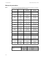
In the table below the measured parameters are shown:
Parameter
group
Parameter
pH/blood gas:
pH (acidity)
pCO2 (carbon dioxide tension)
pO2 (oxygen tension)
Oximetry:
ctHb (total hemoglobin concentration)
sO2 (oxygen saturation)
FO2Hb (fraction of oxyhemoglobin in total hemoglobin)
FCOHb (fraction of carboxyhemoglobin in total
hemoglobin)
FHHb (fraction of deoxyhemoglobin in total hemoglobin)
FMetHb (fraction of methemoglobin in total hemoglobin)
FHbF (fraction of fetal hemoglobin)
Electrolytes:
cK+ (potassium ion concentration)
cNa+ (sodium ion concentration)
cCa2+ (calcium ion concentration)
cCl– (chloride ion concentration)
Metabolites:
cGlu (D-glucose concentration)
cLac (L(+)-lactate concentration)
For details on derived parameters, see section Derived parameters in chapter
8: Parameters in the ABL90 FLEX reference manual.
1-3
1. Introduction
Sensor
cassette
variants
ABL90 FLEX operator's manual
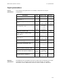
The ABL90 FLEX analyzer comes with different parameter panels, depending on
the sensor cassette installed.
The sensor cassettes are available in the following parameter configurations:
Configuration
Parameters
BG/OXI + QC
pH, pCO2, pO2, ctHb, sO2, FO2Hb, FMetHb,
FCOHb, FHHb, FHbF
BG/LYT/OXI + QC
pH, pCO2, pO2, cCa2+, cCl–, cK+, cNa+, ctHb,
sO2, FO2Hb, FMetHb, FCOHb, FHHb, FHbF
BG/LYT/MET/OXI + QC
pH, pCO2, pO2, cCa2+, cCl–, cK+, cNa+, cGlu,
cLac, ctHb, sO2, FO2Hb, FMetHb, FCOHb,
FHHb, FHbF
For further details on the different sensor cassette variants, see section Analyzer
accessories in chapter 14: Ordering information.
Solution pack
All solutions necessary for the daily operation of the ABL90 FLEX analyzer are
contained in the solution pack, e.g. calibration, rinse and quality control
solutions. Apart from solution consumption in connection with a test, solution is
consumed during a number of automatic activities (e.g. calibration and quality
control) that runs at fixed intervals.
The solution pack contains solutions for 600 activities (tests and automatic
activities) and has a max. lifetime of 30 days. The analyzer performs 12 auto
activities per day. This means that the higher the daily sample volume is, the
more tests can be performed per solution pack – and the shorter the lifetime.
Requirements
The analyzer should be used by personnel trained in using in vitro diagnostic
to the operator medical devices.
NOTICE: Documentation must be consulted. Failure to follow the instructions in
the manual may result in damage to the analyzer. Radiometer will not accept
warranty claims or product liability claims if the recommended procedures are
not followed.
Measurements
on animal
blood
1-4
Animal blood has not been tested on the ABL90 FLEX analyzer. Animal blood
differs from human blood, and variations in the composition of blood from
different animal species may also exist.
ABL90 FLEX operator's manual
1. Introduction
Limitations of use and known interfering substances
Limitations of
use
The following limitations should be taken into consideration:
WARNING – Clinical decisions
The validity of the test results from this analyzer must be carefully
examined by a clinician and related to the patient's clinical
condition, before any clinical decisions are made on the basis of the
test results.
CAUTION – Fulfillment of user-specific analytical needs
Review the analyzer's performance data to ensure that the
performance fulfills the user-specific analytical needs.
FHbF
measurement
The uncertainty in FHbF measurements exceeds the level required to measure
normal HbF levels in the adult range (FHbF reference range is 0-1 %). FHbF is
disabled as default.
The ABL90 FLEX analyzer measures only HbA and HbF hemoglobins.
Known
interfering
substances
For information on the interfering substances, see section Interference tests in
chapter 7: Performance characteristics in the ABL90 FLEX reference manual.
1-5
1. Introduction
ABL90 FLEX operator's manual
Symbols used on the analyzer and accessories
Symbol
Explanation
Product code no.
Lot no.
UL certification
Biological risk
Caution
Consult accompanying documents
Waste electrical and electronic equipment
• Radiometer Medical ApS and its distributors within the
European Union and associated states have taken the
necessary steps to comply with the directive, 2002/96/EC
on waste electrical end electronic equipment (WEEE)
• The instrument, when reaching its end of life, must be
collected and recycled separately from other waste
according to national requirements. Please contact your
local Radiometer distributor for instructions.
Environmental implications: WEEE contains materials that are
potentially hazardous to the environment and to human
health.
Network
USB
Keyboard
Mouse
VGA (monitor)
IOIOI
COM port (scanner/barcode reader)
Mark of compliance with applicable EU Directives
In vitro diagnostic use
Manufactured by
1-6
ABL90 FLEX operator's manual
1. Introduction
Symbol
Explanation
Syringe position of inlet
Capillary position of inlet
Sample mixer
1-7
1. Introduction
ABL90 FLEX operator's manual
Symbols used in this manual
Definitions
The manual contains operational warnings and cautions, which are important
and should be read carefully before performing the related procedures. The
manual also contains important information and a number of helpful hints,
signaled by the word NOTICE.
Symbol
Explanation
WARNING
A warning alerts the reader about a situation, which, if not
avoided, could result in death or serious injury. It may
also describe potential serious adverse reactions and
safety hazards. The designation of a hazard alert as a
"warning" is reserved for the most significant problems.
The term WARNING is generally used as signal word for
this type of hazard alert.
CAUTION
The term precaution is used for the statement of a hazard
alert that warns the reader of a potentially hazardous
situation which, if not avoided, may result in minor or
moderate injury to the user or the patient or damage to
the equipment or other property. It may also be used to
alert against unsafe practices. This includes the special
care necessary for the safe and effective use of the device
and the care necessary to avoid damage to a device that
may occur as a result of use or misuse. The word
CAUTION is generally used as signal word for a
precaution statement.
Manufactured by
1-8
2. What is what
Hardware ................................................................................................. 2-2
Front ................................................................................................. 2-2
Top ................................................................................................... 2-3
Rear ................................................................................................. 2-4
Inlet module ...................................................................................... 2-6
Built-in sample mixer .......................................................................... 2-7
Barcode reader................................................................................... 2-8
Consumables ........................................................................................... 2-9
Sensor cassette pack with sensor cassette ............................................. 2-9
Solution pack ....................................................................................2-10
Software .................................................................................................2-11
Screen elements................................................................................2-11
Initial logon ............................................................................................2-17
Menu structure ........................................................................................2-18
2-1
2. What is what
ABL90 FLEX operator's manual
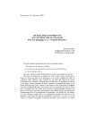
Hardware
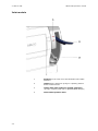
Front
1
Adjustable color touch screen
2
Barcode reader
3
Built-in sample mixer
4
Compartment with sensor cassette
5
Inlet
6
Solution pack
7
Battery pack
The battery pack enables, for a limited period of time, the
performance of measurements and the storage of data
without the analyzer being connected to mains or during
power failure.
2-2
ABL90 FLEX operator's manual
2. What is what
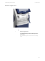
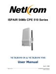
Top
1
Handle
2
USB port
3
Thermal printer
2-3
2. What is what
ABL90 FLEX operator's manual
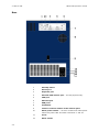
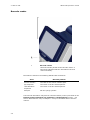
Rear
l
O
2-4
1
Standby button
2
Mouse port
3
Keyboard port
4
External VGA monitor port – for test purposes only.
5
COM port
6
Ethernet port
7
USB ports
8
Ventilation
9
Latch for manual release of the solution pack
10
Mains power switch – on some versions the mains power
switch may show "ON" and "OFF" instead of "l" and "O".
11
Fuses
12
Mains socket
ABL90 FLEX operator's manual
2. What is what
NOTICE: The analyzer should always be placed so that power can be easily
switched off in emergency situations, and so that the ventilation is not covered.
Detachable
power supply
cord
For US
(125 VAC)
UL listed and KAM cord, min. type SV, 18 AWG, 3
conductors. Rated min. 60 °C.
Provided with a molded grounding-type (NEMA 5-15P)
attachment plug rated 125 VAC, min 2.5 A.
Opposite end terminates in molded IEC 320-style
connector rated 125 VAC, min. 2.5 A.
For Europe
(265 VAC)
Cord type min. H05RR-F or min. H05VV-f or min.
H05VVH2-F, rated min. 60 °C, 2 × 0.75 mm2.
Provided with a molded grounding-type attachment plug
rated min. 250 VAC, min 2.5 A.
Opposite end terminates in molded IEC 320-style
connector rated min. 250 VAC, min. 2.5 A.
NOTICES:
• External computing devices connected to the equipment must
comply with the standard, UL 60950 for US and IEC 60950
for Europe. Failure to do so may result in equipment damage.
• The mains supply cord and plug of the equipment must
comply with any national regulation. Failure to do so may
result in equipment damage.
CAUTION: Outside patient environment, place the ABL90 FLEX
analyzer minimum 1.5 meters from patient bed.
2-5
2. What is what
ABL90 FLEX operator's manual
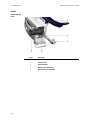
Inlet module
2-6
1
Symbols on the inlet cover that illustrate inlet handle
positions.
2
Handle that is lifted into syringe or capillary position
before measurement.
3
Holder with inlet gasket for sample aspiration
(syringe, capillary, test tube or QUALICHECK adapter)
4
Inlet handle position LEDs
ABL90 FLEX operator's manual
2. What is what
Built-in sample mixer
1
Built-in sample mixer
If a safePICO sampler is placed in the sample mixer,
the ABL90 FLEX analyzer will automatically mix the
blood sample.
Only safePICO samplers can be mixed in the sample
mixer.
2-7
2. What is what
ABL90 FLEX operator's manual
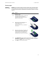
Barcode reader
1
Barcode reader
Hold the barcode parallel to the barcode reader. A
short beep indicates that the information has been
read successfully.
Barcodes are found on the following ABL90 FLEX accessories:
Item
Barcode position
Sensor cassette
The label on the sensor cassette pack.
QC ampoules
The insert in the box with ampoules.
tHb calibration
ampoules
The insert in the box with ampoules.
Sampler
On the syringe cylinder.
The barcode information may also be entered manually in the input fields on the
Patient profile, Patient ID, QC solutions and Replacement screens – see
section Miscellaneous setup in chapter 1: Setup in the ABL90 FLEX reference
manual.
2-8
ABL90 FLEX operator's manual
2. What is what
Consumables
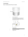
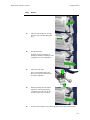
Sensor cassette pack with sensor cassette
1
Sensor cassette pack
The sensor cassette comes in a sensor cassette pack.
For further information about how to remove the
sensor cassette from the sensor cassette pack, see
Sensor cassette in section Replacements in chapter 7:
Replacements in this manual.
Sensor cassette:
1
Reference lid
2
Electrical contact to sensors
3
Oxygen sensor
2-9
2. What is what
ABL90 FLEX operator's manual
Solution pack
1
Biohazard label
Before installation of the solution pack, remove the
top cover of the label on top of the solution pack, so
that the biohazard label appears, to remind you that
the solution pack must be disposed of as infectious
waste after use.
2
Safety pin
To activate a new solution pack, remove the safety pin
and press the lid down (see Solution pack in section
Replacements in chapter 7: Replacements in this
manual for further information).
2-10
ABL90 FLEX operator's manual
2. What is what
Software
Screen elements
Main screen
1
2
3
1
Top section – see below
2
Center section – see later in this chapter
3
Bottom section – see later in this chapter
The main screen appears automatically if the touch screen is idle for more than
3 minutes.
Top section
1
2
4
3
1
Status bar describing the current task of the analyzer
(e.g. calibration, measurement) or its status (e.g.
ready for use, locked).
2
Time bar seen only when the analyzer is performing
an activity. The time bar follows the progress of the
task.
If you are performing a sample or QC measurement, a
calibration, or a cold or warm start, a text appears
underneath the time bar, telling you when the
analyzer approximately will be ready again (e.g.
"Ready within 1 hour").
2-11
2. What is what
ABL90 FLEX operator's manual
3
Parameter bar listing all measurement parameters
available and activated on your analyzer. You may
judge the parameter status at a glance before you
perform a measurement.
4
Shows the number of remaining tests and activities.
Parameter status:
Green
Parameter status is okay; no problem detected on the
given measuring channel.
Yellow
Error associated with the given parameter during the
last calibration or quality control measurement. The
parameter is unreliable and will have a "?" in front of
the result (if requested in the Corrective actions
program (see section Corrective actions, chapter 1:
Setup in the ABL90 FLEX reference manual)).
Red
Serious error associated with the given measuring
channel. The parameter cannot be used at all and will
be displayed as "….."; or a parameter was repressed
in the Parameter setup program (see section
Parameters and input setup, chapter 1: Setup in the
ABL90 FLEX reference manual).
A parameter disabled in the Parameter setup program will be removed from the
parameter bar – see Disabled versus deselected parameter in section Analysis
setup in chapter 1: Setup in the ABL90 FLEX reference manual.
The buttons can be selected in the Access profiles setup programs together with
the access profiles for each operator – for detailed information, see the
description in Access profiles in section Analyzer security in chapter 1: Setup in
the ABL90 FLEX reference manual.
Center section
2-12
1
2
3
1
Icon that describes the screen; it is the same as the
button that gives access to that screen.
2
Screen header (or name).
3
Navigation buttons – see below.
ABL90 FLEX operator's manual
2. What is what
Navigation tools
The first line is highlighted on the
screen. To highlight another line,
touch it on the screen or use…
… Up/down single-arrow scroll
buttons that highlight one item at
a time upward or downward.
… Page up/down double-arrow
scroll buttons that highlight an
item at the top or the bottom of
each screen.
…Left/right single-arrow scroll
buttons that move a text box
horizontally when the box extends
beyond the area available on the
screen.
Interaction tools – text boxes
The first line is highlighted. To
highlight another line, use the
up/down arrows or touch the line in
the box.
Enter the data using the screen
keypad or screen keyboard.
In this text box you can select one
of the predefined options. Use the
up/down arrows to select an item.
If the text box already contains an
entry, it will be overwritten and
cannot be retrieved.
In this manual, text boxes are written in inverted commas, e.g. "Operator". The
same applies to the other elements in the center section of the screen: names
of the columns (e.g. "Status"), input fields (e.g. "Draw time"), etc.
2-13
2. What is what
ABL90 FLEX operator's manual
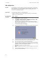
Interaction tools – check buttons
With the check buttons you can enable/disable or select/deselect an item on the
screen. For example:
A function is selected (e.g. acoustic signal if the inlet remains
open) or activated.
A function is deselected or deactivated.
A parameter is selected.
A parameter is deselected.
Interaction tools – screen keypad
Keypad with numerical buttons.
Depending on the screen, the
decimal point may be absent, e.g.
Time/Date setup.
Press the Backspace button to
delete a character from right to left.
The box is cleared as soon as the
first character is typed.
Press Enter (or Select in some
cases) to confirm a numerical entry
and to highlight the next line in the
text box.
To get access to an alphanumerical
keyboard press the keyboard icon.
2-14
ABL90 FLEX operator's manual
2. What is what
Interaction tools – screen keyboard
To enter alphanumerical text, key in the text and press Enter to confirm
the entry and to return to the analyzer screen
To return to the previous screen, without making any entries/changes to
already entered text, press Esc.
Bottom section Buttons
• Each button has an icon and a name placed on it. When pressed, it opens or
closes a screen or a menu.
• The buttons are designated in bold italics in this manual, e.g. Menu, Utilities,
etc.
• The buttons displayed in full color can be activated. A grayed-out button is
currently inactive.
• The buttons can be selected in the Access Profiles setup program together
with the access profiles for each operator – for detailed information, see the
description in Access profiles in section Analyzer security in chapter 1: Setup
in the ABL90 FLEX reference manual.
Note the functions of the following buttons:
Returns you to the previous screen in the same program;
e.g. in the Patient Results log, it will return you from the
Patient identification screen to the Patient result
screen.
Returns you to the Main screen.
2-15
2. What is what
ABL90 FLEX operator's manual
Information bar
The information bar is placed in the lower right corner of the screen.
3 2
2-16
1
1
Clock – shows the current time in the selected format.
2
Date – shows the current date.
3
RADIANCE System icon - shown in the information
bar if connection has been established.
ABL90 FLEX operator's manual
2. What is what
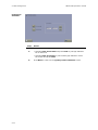
Initial logon
Access rights
The following actions are allowed at analyzer startup:
• Performing a measurement
• Calling a calibration
• Viewing/Editing data in the data logs
• Performing a replacement
Entering
standard
password
Step
Action
1.
Press Menu > Logon on the Main screen.
2.
Type in the standard password: 123456 and confirm with Enter.
3.
Press Menu to access the complete menu – see the previous page.
See General security in section Analyzer security in chapter 1: Setup in the
ABL90 FLEX reference manual for further information about the logon
possibilities.
The access possibilities for each user and their passwords are entered in the
Analyzer Security setup programs – see section Analyzer security in chapter 1:
Setup in the ABL90 FLEX reference manual.
2-17
2. What is what
ABL90 FLEX operator's manual
Menu structure
When the analyzer is taken into use, only the following limited menu is
available.
Press Menu.
Menu
Log on
Latest result
See chapter 2
Setup
See chapter 1 in the
Analyzer status
Calibration programs
Utilities
ABL90 FLEX reference
See chapter 3
manual
Start programs
Disk functions
See chapter 8
See chapter 6
Calibration
Sample counter
tHb calibration
See chapter 1 in the
ABL90 FLEX reference
manual
Temporary shutdown
Auxiliary programs
See chapter 10
Rinse
Liquid sensor adjust
Long term shutdown
Pump calibration
See chapter 10
Tubing refill
RADIANCE browser
See chapter 9
Data logs
Patient results log
See chapter 9
Patient profiles log
Quality control log
Calibration log
Activity log
Replacement log
Archived data logs
2-18
3.
Analyzer status
Analyzer status at a glance ........................................................................ 3-2
Analyzer status elements ........................................................................... 3-3
Calibration status...................................................................................... 3-4
Quality control (QC) .................................................................................. 3-5
Replacements........................................................................................... 3-6
Other activities ......................................................................................... 3-7
System messages ..................................................................................... 3-7
3-1
3. Analyzer status
ABL90 FLEX operator's manual
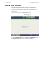
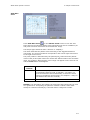
Analyzer status at a glance
The working condition of the analyzer is continuously monitored during its
operation.
To evaluate the analyzer status at a glance before a measurement, use the
following:
• Parameter bar
• Color of the traffic light on the Analyzer status button.
Analyzer status button
To enter the Analyzer status screen, press Menu > Analyzer status or press
the Analyzer status button to access the analyzer status directly.
3-2
ABL90 FLEX operator's manual
3. Analyzer status
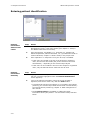
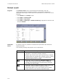
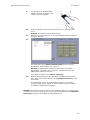
Analyzer status elements
The black triangle indicates
that this is active
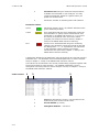
The traffic light color of the Analyzer status button is determined by the traffic
light colors of the following status elements:
Status element
Calibrations
Quality control
Replacements
Other activities
System messages
Color
Indicates
GREEN
OK
YELLOW
Error(s) in the last calibration and/or
calibration schedule reminders.
GREEN
OK
YELLOW
Error(s) in the last QC measurement and/or
QC schedule reminders.
GREEN
No replacements due at the present time.
YELLOW
A replacement is due.
GREEN
No activities due at the present time.
YELLOW
Activity overdue.
GREEN
No (critical) messages.
YELLOW
Non-critical messages.
RED
Critical messages. The analyzer cannot
calibrate or measure.
3-3
3. Analyzer status
ABL90 FLEX operator's manual
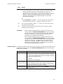
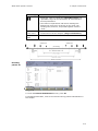
Calibration status
Calibration Type
Lists the most recently performed calibration of each
type and its status:
Calibration was accepted.
?
Error(s) detected during calibration.
Pending or overdue calibration. The last
calibration was accepted.
?
Pending or overdue calibration. The last
calibration was not accepted.
Last time
The date and time that the last calibration of the
specified type was performed.
Next time
The date and time that the next calibration of the
specified type is due according to the calibration
schedule – see section Calibration schedule setup
chapter 1: Setup in the ABL90 FLEX reference manual.
Interval
The time interval between calibrations as set up in the
calibration schedule.
Message
Messages (if present) referring to a highlighted
calibration.
Buttons
• Result: Press to see results
• Calibration: Press to start a highlighted calibration.
3-4
ABL90 FLEX operator's manual
3. Analyzer status
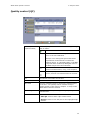
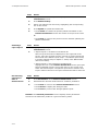
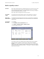
Quality control (QC)
Solution (built-in or
ampoule-based)
Lists the quality control slot and its solution type along
with its status:
The last measurement was accepted.
?
One or more of the following occurred:
Error in the last calibration
Analyzer error during last QC measurement
A parameter measurement is outside the
defined ranges, or a Westgard Rule or RiLiBÄK
range has been violated (if Westgard Rules or
RiLiBÄK ranges have been selected)
The next measurement is overdue, and the
previous measurement, if any, was accepted.
?
The last quality control measurement had
errors, and the next measurement is overdue.
Lot
The solution lot number for the slot.
Last time
The time that the last measurement was performed.
Next time
The next scheduled time to perform the measurement
on the slot – see Quality control schedule setup in
section Quality control setup in chapter 1: Setup in the
ABL90 FLEX reference manual.
QC messages
Messages (if present) referring to a highlighted QC
measurement.
Buttons
• Result: Press to see results
• Start QC: Press to start a QC measurement
• QC Plot: Press to view the plot for the highlighted QC
solution.
3-5
3. Analyzer status
ABL90 FLEX operator's manual
Replacements
Solution pack status, replacement due date and the
number of remaining activities.
Sensor cassette status, replacement due date and the
number of remaining tests.
The printer paper is to be replaced as needed.
Replacement
components
message
3-6
Messages (if present) referring to an activity.
ABL90 FLEX operator's manual
Buttons
3. Analyzer status
• Replace: Press to select one of the replacements
• Status: Press to see status and replacement reasons
of the consumable selected
• Troubleshoot: Press to get troubleshooting
information for the message in question.
Replacement procedures – see chapter 7: Replacements.
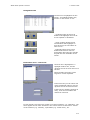
Other activities
Here it is possible to view the scheduled replacements and user activities (see
Replacement schedule setup and User activities in section Replacement setup in
chapter 1: Setup in the ABL90 FLEX reference manual) and to see, if any of the
activities are overdue. To see only overdue replacements/user activities press
Reminders only.
System messages
Here it is possible to view and remedy analyzer messages (see Operator actions
in case of error in section General information in chapter 11: Troubleshooting in
this manual and chapter 10: Analyzer messages in the ABL90 FLEX reference
manual).
3-7
3. Analyzer status
3-8
ABL90 FLEX operator's manual
4. Sample measurement
General information .................................................................................. 4-2
Immediately before analysis ...................................................................... 4-3
Introducing a blood sample with a standard syringe ...................................... 4-4
Introducing a blood sample with a safePICO sampler with barcode ................. 4-5
Introducing a blood sample with a safePICO sampler with barcode and sample
pre-registration ........................................................................................ 4-6
Introducing a blood sample with a capillary tube .......................................... 4-8
Introducing a blood sample with a test tube ................................................. 4-9
Entering patient identification ....................................................................4-10
Patient result ..........................................................................................4-14
Patient result messages ............................................................................4-19
4-1
4. Sample measurement
ABL90 FLEX operator's manual
General information
Available
modes and
parameters
The modes and the measured parameters available on the ABL90 FLEX analyzer
are listed below.
Modes
Syringe – S 65µL,
Capillary – C 65µL
Ampoule - QC
NOTICES:
Parameters
pH, pCO2, pO2, ctHb, sO2, FO2Hb, FCOHb, FHHb,
FMetHb, FHbF, cK+, cNa+, cCa2+, cCl–, cGlu, cLac
All available
• Not all of the above parameters may be available on your
analyzer – it depends on your sensor cassette version
• FHbF is by default disabled
4-2
ABL90 FLEX operator's manual
4. Sample measurement
Immediately before analysis
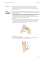
The blood sample must be mixed immediately before it is introduced into the
analyzer to ensure its homogeneity. If a sample is transferred from a sampler to
the analyzer without having been properly mixed, either the plasma phase or
the packed red blood cells may be analyzed, making the oximetry results
meaningless.
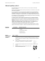
safePICO sampler: Place the syringe in the built-in
sample mixer on the front of the analyzer. The mixer
starts automatically and stops when the sample has
been sufficiently mixed.
Alternatively, invert the syringe repeatedly, roll it
between the palms of your hands and follow your
standard operating procedure.
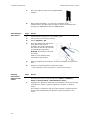
Capillary tube: Mix a capillary sample by gently
moving the mixing wire repeatedly along the length of
the capillary with a magnet. Then move the mixing
wire to the end of the capillary opposite to that from
which the blood is to be aspirated.
Remove both capillary caps.
Test tube: Invert the test tube repeatedly. Then
remove the cap.
CAUTION – Relevant capillary tube volume
Too small capillary volume will give the “Insufficient sample” error.
See chapter 12: Sampling for guidelines on how to handle blood samples.
Before introducing the sample into the analyzer, check the availability and
status of the desired parameters. For detailed information, see chapter 3:
Analyzer status in this manual.
4-3
4. Sample measurement
ABL90 FLEX operator's manual
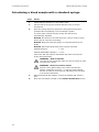
Introducing a blood sample with a standard syringe
Step
Action
1.
Check that the analyzer is in the Ready mode.
2.
Lift the inlet to the syringe position and follow the on-screen
instructions.
3.
Place the syringe tip firmly against the inlet gasket and press it
upwards while still holding on to the sampler cylinder.
The inlet probe extends into the syringe and the blood is
automatically aspirated.
NOTICE: Be careful not to bend the probe. Hold on to the syringe
barrel and do not press the plunger.
NOTICE: Make sure that the plunger is not pushed back by the
probe.
NOTICE: When aspirating small blood volumes less than:
PICO50 samplers:
1.1 mL
PICO70/safePICO70 samplers:
0.7 mL,
make sure that the heparin coated fiber disk does not block the
probe during aspiration.
WARNING – Risk of infection
To avoid the risk of infection take care not to scratch or stab
yourself on the probe.
WARNING - Risk of erroneous results
Press the inlet gasket totally up to make sure that the
sample is aspirated correctly, i.e. from the whole sample
and not just the tip of the syringe. Otherwise this may lead
to erroneous tHb results.
4-4
4.
When prompted by the analyzer, remove the sampler and close the
inlet.
5.
Enter the information needed on the Patient identification screen.
ABL90 FLEX operator's manual
4. Sample measurement
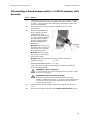
Introducing a blood sample with a safePICO sampler with
barcode
Step
Action
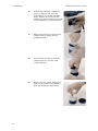
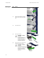
1.
Check that the analyzer is in the Ready mode and scan the sampler
barcode (see Barcode reader in section Hardware, chapter 2: What
is what). Do not remove the safeTIPCAP, the analyzer probe will
pierce the safeTIPCAP.
2.
Lift the inlet to the syringe position and follow the on-screen
instructions.
3.
Place the safeTIPCAP tip
firmly against the inlet
gasket and press it
upwards while still holding
on to the sampler cylinder.
The inlet probe extends
into the syringe and the
blood is automatically
aspirated.
NOTICE: Be careful not to
bend the probe. Hold on to
the syringe barrel and do
not press the plunger.
NOTICE: Make sure that
the plunger is not pushed
back by the probe.
NOTICE: When aspirating small blood volumes less than:
PICO50 samplers:
1.1 mL
PICO70/safePICO70 samplers: 0.7 mL,
make sure that the heparin coated fiber disk does not block the
probe during aspiration.
WARNING – Risk of infection
To avoid the risk of infection take care not to scratch or stab
yourself on the probe.
WARNING - Risk of erroneous results
Press the inlet gasket totally up to make sure that the
sample is aspirated correctly, i.e. from the whole sample and
not just the tip of the syringe. Otherwise this may lead to
erroneous tHb results.
4.
When prompted by the analyzer, remove the sampler and close the
inlet.
5.
Enter the information needed on the Patient identification screen.
4-5
4. Sample measurement
ABL90 FLEX operator's manual
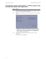
Introducing a blood sample with a safePICO sampler with
barcode and sample pre-registration
Step
Action
1.
Check that the analyzer is in the Ready mode and scan the sampler
barcode (see Barcode reader in section Hardware, chapter 2: What
is what). Do not remove the safeTIPCAP.
2.
If Sample pre-registration has not been selected: Proceed to step 3
below.
• If Sample pre-registration has been selected in the Sample preregistration setup (see section Sample pre-registration setup in
chapter 1: Setup in the ABL90 FLEX reference manual): Proceed
to step 3 below to start the measurement or press Cancel to
cancel the displayed patient data.
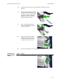
3.
Lift the inlet to the syringe position and follow the on-screen
instructions.
Do not remove the safeTIPCAP.
4-6
ABL90 FLEX operator's manual
Step
4.
4. Sample measurement
Action
Place the safeTIPCAP tip firmly
against the inlet gasket and
press it upwards while still
holding on to the sampler
cylinder. The inlet probe
extends into the syringe and
the blood is automatically
aspirated.
NOTICE: Be careful not to
bend the probe. Hold on to
the syringe barrel and do not
press the plunger.
NOTICE: Make sure that the
plunger is not pushed back by
the probe.
NOTICE: When aspirating small blood volumes less than:
PICO50 samplers:
1.1 mL
PICO70/safePICO70 samplers: 0.7 mL,
make sure that the heparin coated fiber disk does not block the
probe during aspiration.
WARNING – Risk of infection
To avoid the risk of infection take care not to scratch or stab
yourself on the probe.
WARNING - Risk of erroneous results
Press the inlet gasket totally up to make sure that the
sample is aspirated correctly, i.e. from the whole sample
and not just the tip of the syringe. Otherwise this may lead
to erroneous tHb results.
5.
When prompted by the analyzer, remove the sampler and close the
inlet.
6.
Enter the information needed on the Patient identification screen.
4-7
4. Sample measurement
ABL90 FLEX operator's manual
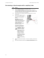
Introducing a blood sample with a capillary tube
Step
Action
1.
Check that the analyzer is in the Ready mode.
2.
Mix the capillary sample by gently moving the mixing wire
repeatedly along the length of the capillary with a magnet. Then
move the mixing wire to the end of the capillary opposite to that
from which the blood is to be aspirated.
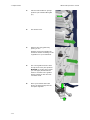
3.
Lift the inlet to the capillary position and follow the on-screen
instructions.
4.
Remove the capillary caps, if
any, and press the capillary
against the inlet gasket as
shown.
NOTICE: To ensure the
right positioning of the
capillary tube, place it in the
center of the inlet gasket
conus. A slight turn of the
capillary tube when
positioning it might assist
with the centering.
The blood is automatically
aspirated when the inlet
gasket is pushed inwards.
WARNING - Risk of
erroneous results
Gently press the inlet
gasket totally in to
make sure that the
sample is aspirated
correctly, i.e. from
the whole sample and
not just the tip of the
capillary tube.
Otherwise this may
lead to erroneous tHb
results.
4-8
5.
When prompted by the analyzer, remove the capillary and close the
inlet.
6.
Enter the information needed on the Patient identification screen.
ABL90 FLEX operator's manual
4. Sample measurement
Introducing a blood sample with a test tube
Step
Action
1.
Check that the analyzer is in the Ready mode.
2.
Lift the inlet to the syringe position and follow the on-screen
instructions.
3.
Place the test tube opening firmly against the inlet gasket holder
and press it upwards while still holding on to the test tube. The inlet
probe extends into the tube and the blood is automatically
aspirated.
NOTICE: Be careful not to bend the probe.
NOTICE: If the inlet probe has difficulties in reaching the blood
sample, we recommend that you transfer the blood sample to a
smaller test tube, or, alternatively, try to tilt the test tube a little, so
that the inlet probe can reach into the blood sample.
4.
When prompted by the analyzer, remove the test tube and close the
inlet.
5.
Enter the information needed on the Patient identification screen.
4-9
4. Sample measurement
ABL90 FLEX operator's manual
Entering patient identification
Entering
information
with barcode
reader
Step
Action
1.
Activate the "Enable general barcode support" function in the
Miscellaneous setup, if not done already (see chapter 1: Setup in
the ABL90 FLEX reference manual).
2.
Scan all barcodes, if available (e.g., Accession no., Sampler ID,
Patient department, Patient last name, etc.) (see Barcode reader in
section Hardware, chapter 2: What is what) in the proper field.
3.
Scan "Operator" or "Physician" from your ID card, if available.
• If the name is included in the list of the analyzer's registered
users, the barcode will identify the person and fill in the name
automatically – depending on the selected input layout
• If the name is not included in the list of the analyzer's registered
users, only the barcode will be read from the ID card
Entering
information
manually
Step
Action
1.
Highlight the desired input field in the Patient identification list (the
top box is already highlighted when the Patient identification
screen appears).
2.
Type in the patient information, using the screen keypad or
keyboard, and confirm each entry with the Enter button.
• If a patient ID has been used before or is included in the Patient
profile log, the relevant input fields will be filled in automatically –
see section Patient profiles log, chapter 9: Data management in
this manual.
• Press Patient lookup (if available) to obtain the latest
information about your patient – see the Patient lookup function
below.
4-10
ABL90 FLEX operator's manual
Step
3.
4. Sample measurement
Action
The analyzer is connected to LIS/HIS:
• Type in the Patient ID or Accession number. If automatic data
request has been selected in Communications setup (see
Automatic data request setup in section Communications setup in
chapter 1: Setup in the ABL90 FLEX reference manual), the
relevant input fields will be automatically filled in with data
received from LIS/HIS.
Or
• Press Request (if available) – after the patient ID or Accession
number has been entered – to fill the relevant text boxes
next to it) text boxes to view
4.
Fill in all the mandatory (with a
the measurement results.
5.
If desired, select another report layout (see next page, section
Selecting a report layout).
NOTICES:
• If the requested patient data (e.g. Patient last name) was
received after the Patient identification screen was exited,
the patient report will be transmitted without the requested
data. To prevent this, select one of the patient ID items
transferred from LIS/HIS as mandatory.
• If the requested patient data (e.g. Patient last name) was
received after the Patient identification screen was exited,
the patient report will be stored without the requested data in
the Patient report log. The data will be stored as a patient
profile in the analyzer's database without, however, being
attached to any patient report. The data can be reused the
next time the same patient ID is used.
Patient lookup
The Patient lookup function allows you to transfer the patient information from a
department's specific list to the Patient identification screen if the following
conditions are fulfilled:
Item
Data source
Conditions
Should be selected in Patient lookup setup (see Patient
lookup setup in section Communications setup, chapter
1: Setup in the ABL90 FLEX reference manual for details)
for the specified data source:
• LIS/HIS
• Analyzer's local database
Exclude from
patient list after …
Number of days that you want each patient to be kept in
the list should be selected (see Patient lookup setup in
section Communications setup, chapter 1: Setup in the
ABL90 FLEX reference manual for details)
Department (Pat.)
Must be included and filled in on the Patient
identification screen.
4-11
4. Sample measurement
ABL90 FLEX operator's manual
Step
Action
1.
Highlight and fill in the "Department (Pat.)" field on the Patient
identification screen.
2.
Press Patient lookup.
3.
Select your patient from the list by highlighting the corresponding
line on the screen.
4.
Press Update to update the Patient list.
5.
• Press Select to transfer the specific patient information to the
Patient identification screen and return to the previous screen
Or
• Press Back to return to the previous screen without updating the
patient information
Selecting a
report layout
Step
Action
1.
Highlight "Report layout" with the up/down arrows on the Patient
identification screen.
2.
• "Report layout" is included in the Patient ID:
Select a layout from the list displayed on the right side of the
screen, using the up/down arrows. (The list of report layouts has
been made in the Patient report setup – see Patient report setup
in section Analysis setup in chapter 1: Setup in the ABL90 FLEX
reference manual).
• "Report layout" is not included in the Patient ID:
Highlight the line on the Patient identification screen (the input
field is separated from the rest of the items on the screen) and
select the desired layout. The patient report will be saved in this
layout. Data not shown in the layout selected will still be archived.
De-selecting
parameters
after a
measurement
Step
Action
1.
Press Parameters on the Patient identification screen.
2.
Deactivate the relevant check button to exclude a parameter.
3.
• Press Back to return to the Patient identification screen
• Press Result to display the changed result
• Press Print to print out the changed patient report
NOTICE: The Selected parameters screen displays all the parameters
selected in the Parameter profile for a given measuring mode.
4-12
ABL90 FLEX operator's manual
4. Sample measurement
Determining FShunt and ctO2(a- v–)
Calculation of
FShunt and
–
ctO2(a-v )
–
To obtain the calculated values of FShunt and ctO2(a-v ), it is necessary
to analyze a mixed-venous and an arterial (or capillary) blood sample from the
patient.
Step
1.
Action
Make, if required, a new patient report layout (see Patient report
setup in section Analysis setup, chapter 1: Setup in the ABL90 FLEX
reference manual) with the following parameters included:
–
• FShunt and/or ctO2(a-v ) into the Patient result
–
–
• pO2(v ), sO2(v ), FO2(I), RQ and T (patient temperature)
into the Patient ID
2.
–
Analyze the mixed-venous sample and record the pO2(v ) and
–
sO2(v ).
3.
Analyze the arterial sample.
4.
On the Patient identification screen, select the sample type as
"Arterial" or "Capillary" and key in the following values:
–
–
• pO2(v ) and sO2(v ) from the mixed-venous sample (step 2
above)
• FO2(I) if it differs from the default value of 0.21 (for FShunt)
• RQ if it differs from the default value of 0.86 (for FShunt)
• T if it differs from the default value of 37 °C (for FShunt)
–
–
NOTICE: The FShunt will be estimated if not all of the inputs (sO2(v ), pO2(v ),
–
–
FO2(I), RQ) are given. A default value for ctO2(a-v ) will be used if pO2(v ) as
–
well as sO2(v ) are not input.
4-13
4. Sample measurement
ABL90 FLEX operator's manual
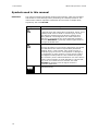
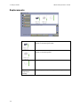
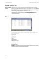
Patient result
Program
The Patient result screen will be displayed automatically when the
measurement has been completed. However, if the patient identification
information took longer to enter than the measurement, you can do one of the
following:
• Press Result on the Ready screen
• Press Menu > Latest result
• Press Menu > My results
• Press Menu > Data logs > Patient results log, highlight the desired result
and press Result
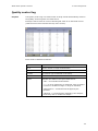
Parameter
status
No marking next to a parameter indicates that a parameter was measured
without any fault.
The following markings may appear next to a parameter:
Marking
"?"
Explanation
• Error in the last quality control measurement or
calibration, or because of sample problems
• Sample age selected for the given parameter(s) in Sample
logistics setup (see Sample age evaluation setup in section
Analysis setup in chapter 1: Setup in the ABL90 FLEX
reference manual) was exceeded
• Parameter value is outside the reference range (the
range within which the parameter value is considered
normal, for the specific type of sample being measured),
but inside the critical limits
• Parameter value is outside the upper or lower critical limit
(the limits outside of which a parameter value is
dangerously high or low, for the specific type of sample
being measured), but inside the reportable range.
4-14
ABL90 FLEX operator's manual
Marking
4. Sample measurement
Explanation
• Parameter value is outside the reportable range. The
reportable range can be selected for all measured and
derived parameters.
• The values of a parameter with these markings are
blanked out and hence not shown in the result. The
markings will, however, be printed together with the
result.
"….." instead
of the value
• A parameter cannot be calculated or exceeds the
numerical limit of the analyzer (range of indication)
"*" next to the
value
• Values with user-defined correction factors
Recalling
patient ID
To recall the Patient identification screen, press ID.
For detailed information, refer to the section Entering patient identification in
this chapter.
4-15
4. Sample measurement
Patient result
approval
ABL90 FLEX operator's manual
Result approval is possible if the "Enable patient result approval" check button
has been activated in the Miscellaneous setup, and only if the analyzer is set up
to LIS/HIS (see section Miscellaneous setup in chapter 1: Setup in the ABL90
FLEX reference manual).
Step
Action
1.
Press Approval on the Patient result screen to display the
following functions:
2.
• Approve
Press Accept to accept the result and to send it to
the connected LIS/HIS.
Press the Keyboard icon to write a note.
Press Cancel to return to the previous screen.
• Reject
Press Accept to reject the result and to send it to
the connected LIS/HIS.
Press the Keyboard icon to write a note.
Press Cancel to return to the previous screen.
• Rerun
Press Accept to mark that the measurement
should be repeated, and to send it to the connected
LIS/HIS.
Press the Keyboard icon to write a note.
Press Cancel to return to the previous screen.
• Note
Press the Keyboard icon to type in a note prior to
the approval or to edit a highlighted note.
To delete a highlighted note, press the Keyboard
icon and delete the note.
NOTICES:
• Once the result has been approved/rejected/rerun, the ID
data can only be viewed, not changed (grayed-out input
boxes). The Parameters, Patient lookup and Request
buttons will not be available either.
• In the Patient report log you can filter patient reports
according to the approval status
• The button changes to Send after the approval of the patient
result has been made (if selected in Communications setup –
see chapter 1: Setup in the ABL90 FLEX reference manual).
4-16
ABL90 FLEX operator's manual
4. Sample measurement
Acid-Base
chart
Press Acid-Base chart
on the Patient result screen to view the acidbase chart for the selected patient result (the button will not be available if pH
and pCO2 have been deselected in the Parameter setup).
The sample type should be either "Arterial" or "Capillary".
The chart illustrates the patient result according to the Siggaard-Andersen
nomogram. The clinical conditions correspond to each of the eight zones listed
to the right of the screen.
The point position is determined by the pH and pCO2 values from the patient
result. If the pH and pCO2 values are outside the defined limits of the acid-base
chart, the message "Measurement out of range" will appear on the chart in red
and the Print button will disappear.
Available
buttons
Press to…
Print
print out the displayed acid-base chart and the
corresponding patient result, if available – see above. To
print the acid-base chart automatically, activate the check
button in the Patient reports setup, (see chapter 1: Setup in
the ABL90 FLEX reference manual).
Back
to return to the patient result screen.
NOTICE: The information provided by the acid-base chart should only be used
as a guideline for interpreting the patient's condition. Patient results must
always be examined carefully by a clinician before a diagnosis is made.
4-17
4. Sample measurement
Patient result
audit trail
ABL90 FLEX operator's manual
Any changes made on the Patient identification screen will be registered in
the audit trail function. The audit trail contains information about the operator
who made the change, time of change and new/old values (changes made at
the same time are indicated with "–" in the Time and User columns).
Messages on the screen is substituted with Log to indicate that changes were
made.
Step
4-18
Action
1.
Press Log on the Patient result screen to display the following
buttons: Audit trail and Messages.
2.
Press Audit trail.
3.
Use the up/down arrows to scroll the list of changes.
4.
Press Back to return to the Patient result screen.
ABL90 FLEX operator's manual
4. Sample measurement
Patient result messages
Screen
messages
Press Messages on the Patient result messages screen.
The Patient result messages screen gives the erroneous parameter(s) and
the message(s) with number(s).
Messages can be seen on the following three levels:
User
Messages for the user familiar with the basic daily operation
of the analyzer and primarily responsible for performing
measurements. This level displays the fewest messages.
Manager
Messages for the user with a deeper knowledge of the
analyzer functions and responsible for the analyzer's proper
operation.
Service
Messages for the service technician with a thorough
knowledge of the operation and construction of the analyzer.
This level displays the greatest number of messages and in
most detail.
The following buttons are available:
Result
Press to return to the Patient result screen.
Troubleshoot
Press to display the error description, operator actions and in
some cases also a removal condition – see chapter 11:
Troubleshooting in this manual and also chapter 10: Analyzer
messages in the ABL90 FLEX reference manual for detailed
information.
Print
Press to print out the screen message(s).
Back
Press to return to the previous screen.
Note
Press to display the keyboard, type the note and confirm
with Enter.
If notes for patient result were entered in the User-defined
notes program (see chapter 1: Setup in the ABL90 FLEX
reference manual), select a note from the list with the
up/down arrows.
To edit a note, press Edit note and type the note on the
keyboard.
Remember to confirm it with Enter on the keyboard.
To delete a note, press Delete note.
4-19
4. Sample measurement
4-20
ABL90 FLEX operator's manual
5. Quality management
Automatic quality management system ....................................................... 5-2
General information .................................................................................. 5-3
Built-in quality control ............................................................................... 5-5
System checks ......................................................................................... 5-7
Analysis check .......................................................................................... 5-8
Manual quality control ............................................................................... 5-9
Manual quality control ............................................................................... 5-9
Additional quality control ..........................................................................5-13
5-1
5. Quality management
ABL90 FLEX operator's manual
Automatic quality management system
With the ABL90 FLEX quality management system, all necessary checks are
done automatically and continuously by the analyzer.
If the result of the check is not acceptable, the analyzer automatically performs
a corrective action, unless a user intervention/action is required.
Checks and corrective actions are logged in the activity log of the analyzer and
can be obtained if documentation is needed.
The quality management system is based on the following checks:
• Built-in QC
• System checks
• Analysis check (performed before, under and after each activity)
Quality management is performed on six different solutions that are all built into
the solution pack. Three solutions (CAL1, CAL2, CAL3) are used for calibration,
analysis check and system check, and three solutions (QC1 (S9030), QC2
(S9040), and QC3 (S9050)) are used for quality controls.
5-2
ABL90 FLEX operator's manual
5. Quality management
General information
Purpose
The purpose of quality control is to evaluate the performance of the analyzer to
ensure the reliability, accuracy, and precision of patient sample results.
Quality controls are run automatically on the built-in solutions in the solution
pack.
Furthermore, the ABL90 FLEX analyzer automatically performs periodic system
checks and continuous analysis checks to provide further confidence in the fact
that the analyzer is performing according to specifications (see descriptions later
in this chapter).
Built-in QC measurements are by default performed every 8 hours. Additional
Quality controls should be run after all troubleshooting or preventive
maintenance procedures that may alter the performance of the analyzer or
whenever a service technician has doubts about the performance of the
analyzer. It is also possible to run manual QC with glass ampoules and to start
an unscheduled built-in QC measurement (see later in this chapter).
QC should be performed according to:
• internal quality assessment procedures
• local, state or federal regulation
Glossary list
The following terms are used in the quality management:
Term
Explanation
Accepted result
A measurement value which falls within the statistics range.
Assigned value/
target value
The assigned value is the center value of the control range.
Control range
The range within which a measurement should fall. Typically
the control range is set to be the mean ± 2 SD (see section
Quality control setup in chapter 1: Setup in the ABL90 FLEX
reference manual). This range can be set by using the lotto-date range (2 SD) calculated by the analyzer, or it may
be user-defined.
Insert range
The upper and lower control ranges are established by
Radiometer. On built-in QC they are given automatically
when the solution pack is installed. On manual QC with
glass ampoules they are found on the insert provided with
each box of control solutions.
Lot-to-date range
A range calculated by the analyzer from measurements
taken on a lot of a particular control solution. It is
represented by mean ± 2 SD.
Range of
indication
The range for each parameter that the analyzer physically is
capable of measuring. Refer to Measured parameters,
chapter 13: Specifications for the analyzer range of
indication for each parameter.
Statistics factor
The factor by which the control range is expanded
(multiplied by) to determine the statistics range. The
recommended statistics factor is 1.5.
Statistics range
The range within which a measurement must fall in order to
be included in the quality control statistics. It is determined
by multiplying the control range limits by the entered
statistics factor. It is typical that the statistics range is set
to the mean ± 3 SD.
5-3
5. Quality management
ABL90 FLEX operator's manual
For detailed information on terminology and principles for the quality control
systems, see I Appendix - Quality control in the ABL90 FLEX reference manual.
5-4
ABL90 FLEX operator's manual
5. Quality management
Built-in quality control
Schedule
Built-in QC measurements are by default performed every 8 hours (one on each
level). The interval of these events can be defined by the user in the Quality
control schedule setup program – see section Quality control setup in chapter 1:
Setup in the ABL90 FLEX reference manual.
Built-in QC results are assigned to the slots A, B and C.
Acceptable
ranges
The assigned value and acceptance range for each parameter are entered
automatically into the analyzer each time a new solution pack is installed.
Built-in QC
measurement
A scheduled QC measurement will start on time, provided that no calibrations
are pending. A pending calibration will be performed before the scheduled QC
measurement.
View built-in
QC results
Press Result:
• on the Quality control identification screen
• from Menu > Analyzer status > Quality control
• from the Quality control log
The measured values are compared with the defined control range, statistics
range and range of indication, and then given a status mark accordingly.
NOTICE: The user-defined corrections (slope and offset) do not influence the
quality control results, unless the "Apply parameter corrections to QC" function
has been activated in Miscellaneous setup – see chapter 1: Setup in the ABL90
FLEX reference manual.
5-5
5. Quality management
Parameter
status
ABL90 FLEX operator's manual
The absence of any markings next to a parameter indicates that a parameter
was measured without fault.
Marking
Explanation
?
Error in the previous calibration, or analyzer malfunction.
W
A violated Westgard rule.
R
A violated RiLiBÄK rule.
Parameter value is outside the control range, but inside the
statistics range.
Only the values within the statistics range are considered
accepted and are included in the QC statistics.
Parameter value is outside the statistics range and is not
included in the statistics.
Parameter value is outside the range of indication.
Measurement is not included in the statistics.
*
…..
Parameter values with user-defined corrections – see
Parameter setup in section Parameters and input setup in
chapter 1: Setup in the ABL90 FLEX reference manual for
details.
Parameter value could not be calculated, most likely due to a
system error or malfunction. These values will for the most
part be accompanied by a "?". To obtain a possible
explanation, press Message.
To evaluate the analyzer quality control status at a glance, enter the Analyzer
status screen. Fur further information about the analyzer quality control status
see section Quality control (QC) in chapter 3: Analyzer status.
Unscheduled
built-in QC
measurement
To start an unscheduled built-in QC measurement, do the following:
Step
Action
1.
Press Menu > Analyzer Status > Quality Control.
2.
Highlight the built-in QC solution to run an unscheduled
measurement on.
3.
Press Start QC to start the measurement.
The Quality control result is shown after the measurement is completed.
Reference
5-6
If the built-in QC results are outside the acceptable control ranges, follow the
instructions on the Troubleshooting screen (the instructions are also given in
Chapter 10: Analyzer messages in the ABL90 FLEX reference manual).
ABL90 FLEX operator's manual
5. Quality management
System checks
Description
The ABL90 FLEX analyzer performs system checks to verify that the individual
components of the analyzer are functioning properly and according to
specifications.
System checks are performed regularly and automatically. In this way the ready
time is maximized and long-termed activities and frequent calibrations are
avoided. It is not necessary for the user to make any additional checks if this is
not requested by the analyzer.
If the system checks fail, they are in most cases retried, and, if possible,
remedied automatically by the analyzer. If these system checks fail again, the
analyzer enters the user-intervention-required or user-action-needed mode.
This means that if any interventions/actions are required by the user, the User
Intervention Required or the User Action needed screen appears with
instructions on what to do to in the particular case.
The system checks consist of the following checks:
• Computer checks
• Software checks
• Mechanical checks
• Electronical checks
• Temperature checks
• Consumable integrity checks on time of installation
The system checks are performed at different times and with different intervals,
depending on the checks that are to be performed. Some checks are performed
once a day, some with every rinse, and others every 10 seconds.
For further information on the individual checks please refer to section Quality
management in chapter 5: Sensors and measuring technologies in the ABL90
FLEX reference manual.
5-7
5. Quality management
ABL90 FLEX operator's manual
Analysis check
Description
During analysis – be it a patient sample analysis, a calibration or a QC
measurement – the analyzer performs different checks automatically to verify
that the analyzer is functioning properly before, under and after measuring
activities.
If the analysis checks fail, they are in most cases retried, and, if possible,
remedied automatically by the analyzer. If these analysis checks fail again, the
analyzer enters the user-intervention-required or user-action-needed mode.
This means that if any interventions/actions are required automatically or by the
user, the User Intervention Required or the User Action Needed screen
appears with instructions on what to do to in the particular case.
The analysis checks consist of the following checks:
• Status calibrations/checks
• Sample integrity checks
• Temperature checks
• Mechanical checks
• Electronical checks
• Measurement preparation checks
• Consumable checks
The analysis checks are performed every second hour according to the default
scheduled analysis activities (calibrations and QC measurements) and in
connection with patient sample measurements.
For further information on the individual checks please refer to section Quality
management in chapter 5: Sensors and measuring technologies in the ABL90
FLEX reference manual.
5-8
ABL90 FLEX operator's manual
5. Quality management
Manual quality control
As an alternative to built-in quality controls, you may analyze manual QC
samples, if desired.
Quality control measurements should be performed in accordance to local, state
and federal regulations.
It is recommended to use QC material from Radiometer (the QUALICHECK5+
control system) to ensure an optimal performance of the analyzer and to take
advantage of features such as temperature correction and automatic QC level
detection. See I Appendix - Quality control in the ABL90 FLEX reference manual.
It is possible to use non-Radiometer solutions although the accuracy and validity
of the results cannot be guaranteed.
To assign a quality control solution to a specific slot or to change the quality
control solution of a slot, see Manual quality control (QC) solutions in section
Quality control setup in chapter 1: Setup in the ABL90 FLEX reference manual.
NOTICE: Changing a control solution assigned to a slot will delete all current
quality control statistics obtained on that slot. If you want a copy of the
statistics for the last QC month, create a WDC Report – see chapter 2: Disk
Functions setup programs in the ABL90 FLEX reference manual.
To schedule a QC measurement, see Quality control schedule setup in section
Quality control setup in chapter 1: Setup in the ABL90 FLEX reference manual.
Required
materials
QC system
QUALICHECK5+
Materials required
• Four levels of QC solutions (S7730, S7740, S7750,
S7760)
• QUALICHECK adapter
• Rubber gloves
• Ampoule opener
Before
measurement
on a control
solution
Step
1.
Action
QC ampoules must be conditioned before measurement. Store the
ampoules for 5 hours at a constant temperature between 18-32 °C.
Control solutions are sensitive to light, so always keep the ampoule
box closed.
2.
Hold the ampoule between two fingers as shown
and shake it vigorously for at least 15 seconds.
3.
Tap the top of the ampoule until all of the solution collects at the
bottom.
4.
Place the ampoule in the ampoule opener and
break off the ampoule neck.
2
1
5-9
5. Quality management
Introducing a
QC solution
ABL90 FLEX operator's manual
5.
Place the ampoule fully into the QUALICHECK
adapter.
6.
Open-ampoule stability: To ensure the reliability of the
measurement, each QC ampoule must be used immediately after
opening, for one measurement on one analyzer.
Step
Action
1.
Check that the analyzer is in the Ready mode.
2.
Lift the inlet to the syringe position.
3.
Select Ampoule - QC.
4.
Place the adapter tip against the
inlet gasket and press it
upwards. The probe extends into
the ampoule and the QC solution
is automatically aspirated.
NOTICE: Be careful not to bend
the probe.
Hold on to the adapter when
removing the QC solution.
5.
When prompted by the analyzer, remove the adapter and close the
inlet.
6.
Dispose of used ampoules as infectious waste*.
* Clinical laboratory waste management. CLSI document GP5-A2.
Entering
information
with barcode
reader
Step
Action
1.
Activate the "Enable general barcode support" check button in
Miscellaneous setup, if not already done (Menu > Utilities >
Setup > General setup > Miscellaneous setup).
2.
Highlight the "Operator" field and scan "Operator" from your ID card
(see Barcode reader in section Hardware in chapter 2: What is
what).
If the name is included in the list of the analyzer's registered users,
the barcode automatically will identify the person and fill in the
name.
5-10
ABL90 FLEX operator's manual
Entering
information
manually
Step
1.
5. Quality management
Action
Highlight the item to be edited, using the up/down arrows.
• The solution is entered automatically. Choose the specific slot
from the screen.
• Lot is entered automatically if only one lot for each solution is
used. Otherwise highlight the desired item on the screen and
confirm with the Enter button.
2.
Enter the ambient temperature (default: 25 °C) on the keypad and
confirm with the Enter button.
Mandatory entry is indicated by a
.
3.
Enter "Department" on the keypad and confirm with the Enter
button.
4.
Enter "Operator" on the keypad or keyboard and confirm with the
Enter button (filled in automatically when operator is logged on).
The measured values are compared with the defined control range, statistics
range and range of indication, and then given a status mark accordingly.
NOTICE: The user-defined corrections (slope and offset) do not influence the
quality control results, unless the "Apply parameter corrections to QC" function
has been activated in Miscellaneous setup (see section Miscellaneous setup in
chapter 1: Setup in the ABL90 FLEX reference manual).
View manual
QC results
In most cases the Quality control result screen will be displayed automatically
when the measurement has been completed. However, if the QC identification
took longer time to enter than the measurement, you can press Result:
• on the Quality control identification screen
• from Menu > Analyzer status > Quality control
• from the Quality control log.
Parameter
status
The absence of any markings next to a parameter indicates that a parameter
was measured without fault.
For an explanation of possible parameter markings, please refer to Parameter
status in section Built-in quality control earlier in this chapter.
5-11
5. Quality management
ABL90 FLEX operator's manual
Unknown
solutions
Quality control on a solution, identified as unknown, are not compared with any
previous measurements or statistics, and, therefore, do not receive any status
marking. The parameter results for unknown levels cannot be plotted and are
not included in any statistical data unless later changed to a defined slot.
Temperature
corrections
For QC solutions from Radiometer, temperature corrections are made
automatically with the typed-in temperature.
For non-Radiometer QC solutions, temperature corrections must be made
manually. Refer to the manufacturer's literature for procedure.
Reference
For a detailed explanation of the evaluation of results, refer to I Appendix Quality control in the ABL90 FLEX reference manual. If the results are outside
the acceptable control ranges, please refer to Chapter 10: Analyzer messages in
the ABL90 FLEX reference manual or follow the instructions on the
Troubleshooting screen.
Recalling
quality control
identification
To change data that can be edited (non-gray lettered) on the screen, press QC
ID.
NOTICES:
• If leaving the Quality control identification screen without
entering a temperature, the previous temperature will be
recalled
• Changing the temperature will initiate recalculation of the last
result. It will be substituted by the recalculated result, and
the statistics will also be recalculated. In case the
temperature is mandatory, the result cannot be viewed until
it is entered.
5-12
ABL90 FLEX operator's manual
5. Quality management
Additional quality control
If there is a need for more extreme QC values than those given in the built-in
QC system or in the manual QUALICHECK5+ system, it is recommended to use
the Metabolite+ QUALICHECK solution.
As the analyzer software will not recognize Metabolite+ QUALICHECK solution as
a control solution, you have to select a blood mode before you introduce
Metabolite+ QUALICHECK solution into the analyzer.
5-13
5. Quality management
5-14
ABL90 FLEX operator's manual
6. Calibration
General information .................................................................................. 6-2
tHb calibration.......................................................................................... 6-4
Calibration result ...................................................................................... 6-5
Calibration verification ............................................................................... 6-8
6-1
6. Calibration
ABL90 FLEX operator's manual
General information
Purpose
The calibration process determines and checks the accuracy with which the
analyzer measures its parameters. The process is therefore important in
ensuring the reliability of results.
Calibrations are performed with solutions and ambient air for each of the
measured parameters.
Calibration
programs
All calibration results are automatically recorded in the Calibration log from
which they can be viewed and printed. See section Calibration log in chapter 9:
Data management for details.
The calibration process and a detailed explanation of the terms are described in
chapter 3: Wet section and chapter 5: Sensors and measuring technologies in
the ABL90 FLEX reference manual.
Calling an
unscheduled
calibration
Step
Action
1.
Check that the analyzer is in the Ready mode.
2.
Press Menu > Start programs > Calibration programs and call
a calibration.
The following options are available:
• calibration
• tHb calibration
If a button is grayed out, a calibration cannot be called.
Calibrations
related to
startups
Due to significant drift, the cGlu, cLac, Oxi, and pCO2 calibrations have a
reduced validity time for the first 24 hours after cold starts and sensor cassette
replacements.
T
T
T
T
The first 24 hours, the validity time of the cGlu, cLac, Oxi, and pCO2 calibrations
gradually increases to 4 hours (the span between scheduled calibrations).
T
T
T
T
During the first 4 hours, no additional calibrations are scheduled, but a
measurement takes up to 3 minutes because a calibration is performed with
every measurement.
After 4 hours, calibrations are run in fixed intervals according to the table below
and a measurement takes 35 seconds.
Time installed
Time between calibrations
0-4 hours
0 minutes (performed with every measurement)
4-6 hours
15 minutes
6-8 hours
30 minutes
8-12 hours
60 minutes
12–24 hours
240 minutes
If the analyzer is only turned off for a short period of time and certain
preconditions are fulfilled, a warm start may be performed instead of a cold
start. For further information about the warm start and the preconditions, see
section Warm start in chapter 10: Analyzer shutdown.
6-2
ABL90 FLEX operator's manual
Pending
calibrations
6. Calibration
A calibration is pending when a scheduled calibration cannot be performed at
its scheduled time because the analyzer is occupied with another activity, e.g.
measurement.
A pending calibration:
• is indicated by a clock symbol next to it on the Analyzer status >
Calibrations screen as a warning
• will be performed 3 minutes after the analyzer has returned to the Ready
mode and been without any activity. If more than one type of calibration are
pending, the highest-priority calibration is performed. The calibrations are
given in descending order of priority, the full calibration having the highest
priority.
A scheduled QC measurement will be postponed until the calibration has been
performed.
Expired
calibrations
A calibration has expired and is considered invalid when:
• a sensor cassette is replaced
• If a calibration is 25 % overdue.
Under these conditions a "Cal expired (parameter)" message appears in the
Activity and System messages logs, and the replaced item is also recorded in
the Activity log. The analyzer status in the status bar is RED.
6-3
6. Calibration
ABL90 FLEX operator's manual
tHb calibration
Purpose
This calibration is used to adjust the analyzer's optical system (cuvette factor
and wavelength). It is recommended that a tHb calibration is performed every
three months on S7770 ctHb Calibration Solution. The calibration can be
included in the Calibration schedule.
Preparation
• Check that the analyzer is in the Ready mode
• Prepare an ampoule of S7770 ctHb Calibrating Solution, an QUALICHECK
adapter and an ampoule opener
tHb calibration
procedure
Step
Action
1.
Press Menu > Start programs > Calibration programs >
Calibration to perform a calibration
2.
Press Menu > Start programs > Calibration programs > tHb
calibration to perform the tHb calibration.
Enter the barcode information from the S7770 insert, using the
barcode reader (see Barcode reader in section Hardware, chapter 2:
What is what) or the keyboard.
To cancel the program, press Close.
3.
When the barcode has been accepted, the following screen appears.
4.
Tap the top of the S7770 ampoule to collect the liquid at the bottom
and break off the ampoule neck, using the ampoule opener.
5.
Place the ampoule fully in the QUALICHECK adapter.
6.
Place the adapter tip against the inlet gasket and press the adapter
upwards. The probe extends into the ampoule and the S7770 ctHb
Calibration Solution is automatically aspirated.
NOTICE: Be careful not to bend the probe.
6-4
7.
When prompted by the analyzer, remove the adapter and close the
inlet.
8.
If the calibration results are not accepted, remedy the error and
perform a new tHb calibration.
ABL90 FLEX operator's manual
6. Calibration
Calibration result
Viewing a
calibration
result
The result can be viewed as soon as the calibration is completed. Results from
the most recent calibration can be viewed via Menu > Analyzer status >
Calibration > Result or via the Calibration log.
Calibration
result
Button
Function
Press to display the remainder of the calibration result.
Messages
Press to display the interpretation of any detected errors.
Print
Press to print out the result.
Send
Press to send the result to a connected LIS/HIS system.
6-5
6. Calibration
ABL90 FLEX operator's manual
Calibration data are grouped together by parameter:
Bold characters
Indicate data updated during this calibration.
Gray characters Black parameters origin from the last calibration and gray
parameters may origin from multiple earlier calibrations.
?
Indicates an error or that the value is outside the
recommended range, such as:
• Drift value outside the drift tolerances – shown as a
message, not a value
• Status outside the default limits
• Sensitivity outside the default limits
.….
Indicates that the value could not be calculated, most likely
due to a system error or malfunction. These values will for
the most part be accompanied by a "?". Press Messages for
the explanation of the error.
tHb calibration
result
Sens. (cuvette factor) is a factor that expresses the ratio of the effective light
path of the analyzer cuvette to that of a reference cuvette determined by
Radiometer.
The value should lie between 80% and 120% and have no errors, i.e. no "?" in
it.
6-6
ABL90 FLEX operator's manual
Calibration
result
messages
6. Calibration
Press Messages on the Calibration result screen to display the Calibration
result messages screen.
The message levels can be considered as a type of filter in which the messages
displayed are based on the following:
Level
Explanation
User
Messages for the user familiar with the basic daily operation of
the analyzer and primarily responsible for performing
measurements. This level displays the fewest messages.
Manager
Messages for the user with a deeper knowledge of the analyzer
functions and responsible for the analyzer's proper operation.
Service
Messages for the service technician with a thorough knowledge of
the operation and construction of the analyzer. This level displays
the greatest number of messages and in most detail.
6-7
6. Calibration
ABL90 FLEX operator's manual
Calibration verification
Purpose
Regulations in some countries require verification of the reportable ranges
selected for the measured parameters, and a special feature - described below is provided to assist in the collection of this data.
Once the reportable ranges are established (follow your local, state and federal
guidelines), the limits may be entered in the Reportable ranges program
described in Analysis setup, chapter 1: Setup in the ABL90 FLEX reference
manual.
Setting up the
Calibration
Verification
mode
NOTICE: Once the first measurement in this mode has been done, the mode is
available for the next 7 days. In the 14-day period that follows, the Calibration
Verification mode is not available as measuring mode.
This is how the Calibration Verification mode is set up:
Step
Action
1.
Tap Menu > Utilities > Setup > Analysis setup > Syringe
modes.
2.
Tap a button with no text in the "Select button to set up" field.
3.
Select the Button is enabled: check button.
4.
Tap the arrows in the "Measuring program:" field, until Cal.
Verification is shown on the button.
NOTICE: Cal. Verification will only be shown on the button, not in
the “Measuring program:” field.
5.
Tap the Close button.
This procedure is only to be done when you set up the analyzer.
Calibration
verification
procedure
The Cal. Verification mode is a preset measuring mode that lets you analyze
solutions for calibration verifications as patient samples.
Radiometer recommends that Radiometer QUALICHECK solutions are used for
the calibration verification.
Step
6-8
Action
1.
Condition the Radiometer QC solution – see section Manual quality
control in chapter 5: Quality management of this manual.
2.
Hold the ampoule between your thumb and first finger and shake it
vigorously for a minimum of 15 seconds.
3.
Hold the ampoule neck-side up and tap the top until all solution
collects in the lower part of the ampoule.
4.
Put the ampoule in the Ampoule Opener and break off the neck of
the ampoule.
5.
Put the QUALICHECK Adapter over the open end of the ampoule.
6.
Check that the analyzer is in the Ready mode.
7.
Lift the inlet to the syringe position.
8.
Tap the Cal. Verification button.
ABL90 FLEX operator's manual
9.
10.
6. Calibration
Put the tip of the QUALICHECK
Adapter with the ampoule in the
center of the inlet gasket.
Push the adapter into the analyzer as far as you can and hold it
there.
NOTICE: Be careful not to bend the probe.
11.
When the analyzer tells you, remove the adapter with the ampoule
and close the inlet.
12.
As “Patient ID” In the Patient identification screen, enter an
identifier for each solution (e.g. Level 1).
NOTICE: No temperature corrections will be done. For manual
temperature corrections, see I Appendix - Quality control in the
ABL90 FLEX reference manual.
The results are saved in the Patient results log.
13.
After all measurements on the calibration verification solutions have
been done, use the filter function in the Patient results log to see
the results.
To transfer the results to a data analysis program, see section
Exporting data logs in chapter 2: Disc functions setup programs in
the ABL90 FLEX Reference manual.
NOTICE: Once the first measurement in this mode has been done, the mode is
available for the next 7 days. In the 14-day period that follows, the Calibration
Verification mode is not available as measuring mode.
6-9
6. Calibration
6-10
ABL90 FLEX operator's manual
7.
Replacements
Screens during replacements ..................................................................... 7-2
Replacements........................................................................................... 7-3
Solution pack ..................................................................................... 7-4
Sensor cassette .................................................................................. 7-5
Printer paper ...................................................................................... 7-9
Inlet ................................................................................................7-10
Cleaning the analyzer ...............................................................................7-16
7-1
7. Replacements
ABL90 FLEX operator's manual
Screens during replacements
The screens during replacements have an animation on the left side of the
screen and the activities/operator actions on the right side of the screen.
General remarks:
An arrow indicates a procedure in progress.
The triangle with an exclamation mark indicates a precaution
where operator action should be taken.
7-2
ABL90 FLEX operator's manual
7. Replacements
Replacements
Viewing
replacement
status
Step
Action
1.
Press Menu > Analyzer status > Replacements > Status.
2.
Choose one of the following options:
• Send status to printer:
For a printout of the consumables
status, showing the replacement
information of the solution pack and
the sensor cassette, such as date of
installation, scheduled replacement
date, reason for the replacement,
time for next replacement, expiration
date, number of blood and QC
measurements performed and
number for samples remaining.
• Sensor status:
Shows replacement information, such
as date of installation, scheduled
replacement date, reason for the
replacement, time for the next sensor
cassette replacement, when a new
sensor should be conditioned, how
many tests have been performed and
when the sensor cassette expires.
• Solutions status:
Shows replacement information, such
as date of installation, scheduled
replacement date, reason for the
replacement, time for the next
solution pack replacement, the lot
number of the solution pack, how
many activities have been performed
and when the solution pack expires.
3.
Press Back to return to Analyzer Status screen.
4.
Press Close to return to the main screen.
7-3
7. Replacements
ABL90 FLEX operator's manual
Solution pack
Replacing
solution pack
Step
Action
1.
Press Menu > Analyzer status > Replacements > Replace >
Replace solutions.
2.
Lift the inlet to the capillary position
and wait for the solution pack to
unlock.
3.
Remove the used solution pack and
dispose of it as infectious waste
according to the regulations in your
institution.
4.
Activate the new solution pack by
pulling out the safety pin.
5.
Press the lid firmly down by pressing
the elevated side (where the safety pin
was) down until the side taps click into
the side tap holes.
Side taps holes
Side taps
7-4
6.
Remove the top layer of the label on
top of the solution pack, so that the
biohazard label appears to remind you
that the solution pack after use must
be disposed of as infectious waste.
7.
Insert the new solution pack by
pushing it fully into place in the
analyzer until a click is heard.
8.
When prompted by the analyzer, close the inlet.
9.
Enter operator name and any notes, using the Keyboard or the
Note button to display the keyboard and to enter the operator
name/note. Confirm the entry with the Enter button on the
keyboard.
ABL90 FLEX operator's manual
10.
7. Replacements
Press OK to restart the analyzer.
NOTICE:
By default a QC will be performed after a solution pack
replacement. However, if this function has been deactivated, it is
recommended to perform a built-in QC after solution pack
replacements to assure that the consumables have not been
damaged.
Manual release In emergency situations, e.g. during a power failure or if for some reason the
of the solution analyzer is down, it is possible to release the solution pack by pressing the latch
on the rear of the analyzer. See Rear in section Hardware, chapter 2: What is
pack
What.
Sensor cassette
From the factory, the sensor cassette comes dry-stored in the sensor cassette
pack to ensure a long shelf life. Therefore, a conditioning process where rinse
solution is released to the sensors must occur before the sensor cassette can be
used for measurements.
When conditioning the sensor cassette in the analyzer, it typically takes 2-4
hours (including a calibration) for the sensor cassette to be ready for
measurement.
If the conditioning by the analyzer is interrupted by the user by pressing Exit
conditioning, some of the parameters may subsequently have a "?" in front of
them.
Replacing
sensor cassette
Step
Action
1.
Press Menu > Analyzer status > Replacements > Replace >
Replace sensors.
2.
Register the sensor cassette
• by scanning the barcode of the sensor cassette pack (see Barcode
reader in section Hardware, chapter 2: What is what).
• by entering the barcode manually by pressing the keyboard
button and entering the missing numbers of the barcode of the
sensor cassette. Confirm with Enter and press Continue.
If no barcode is available, press No Barcode in the "Registration"
field. Thereafter, press the
button.
The sensor cassette compartment opens.
7-5
7. Replacements
7-6
ABL90 FLEX operator's manual
3.
Remove the old sensor cassette by
pulling it upwards and out of the
compartment with thumb and index
finger. Dispose of the used sensor
cassette as infectious waste according
to the regulations in your institution.
4.
Remove the foil on top of the sensor
cassette pack by pulling the foil
upwards and off.
5.
Screw off the revealed lid of sensor
cassette pack, by screwing it off
counterclockwise.
6.
Remove the new sensor cassette by
pulling it out of the sensor cassette
pack with thumb and index finger.
ABL90 FLEX operator's manual
7. Replacements
7.
Holding the new sensor cassette with
the thumb and index finger, press the
new sensor cassette firmly into the
sensor cassette seat in the sensor
compartment until resistance is met.
8.
Press Proceed. The sensor cassette compartment closes and a new
Replacing sensor cassette screen appears.
9.
Enter operator name and any notes, using the Keyboard or the
Note button to display the keyboard and to enter the operator
name/note. Confirm the entry with the Enter button on the
keyboard.
10.
Press OK to finish or press Replace solutions to replace the
solution pack too – see Solution pack earlier in this chapter.
11.
Wait until the restart sequence has been finished.
NOTICES:
• By default, a QC will be performed after a sensor cassette
replacement. However, if this function has been deactivated,
it is recommended to perform a built-in QC after sensor
cassette replacements to assure that the consumables have
not been damaged.
• It is only recommended to remove the sensor cassette from
the sensor cassette compartment if you want to replace the
old sensor cassette with a new one. If, however, it becomes
necessary to remove it for a short period of time (e.g. during
a troubleshooting procedure etc.), the sensor cassette must
be placed back into the sensor cassette compartment within 2
hours. During removal it must be placed in an upright position
and not on the side:
7-7
7. Replacements
ABL90 FLEX operator's manual
Startup after sensor cassette replacement
The calibration status is checked 1, 2 and 3 hours after sensor startup, e.g.
after replacements or when the power is turned on.
If a parameter (except for the oximetry parameters) is marked with a "?", a recalibration of the relevant parameter is performed if the analyzer is in the ready
mode.
The internal QC status is checked 1, 2 and 3 hours after sensor startup, and
once every 4 hours after any calibration performed. The calibrations are
scheduled every 4 hours and the 4-hours checks continue up to 24 hours after
sensor startup.
If a built-in QC level is marked with a "?" for a given parameter (except for the
oximetry parameters) and the calibration status is OK, the relevant QC levels
are re-scheduled and performed according to the schedule.
These checks accelerate the time for all parameters being ready after a sensor
cassette replacement. The parameters are ready when there is a green traffic
light in the analyzer status.
7-8
ABL90 FLEX operator's manual
7. Replacements
Printer paper
Replacing
printer paper
NOTICE: Avoid contact of paper with direct sunlight, water, high temperature
and humidity, alcoholic and organic solvents, PVC-containing materials, freshly
developed diazo copy sheets, extensive pressure and scratching. For storage,
use folders and cases made of polyethylene, polypropylene, polyester or similar
material.
Step
Action
1.
Press Menu > Analyzer status > Replacements > Replace >
Replace paper.
2.
Press the release button to unlock the
lid. Open the lid by pressing it
backwards and remove any leftover
paper from the printer.
3.
Place the new roll in the printer so
that the paper unreels from
underneath the roll.
Align the paper roll in the middle of
the printer.
4.
Make sure that some of the paper will
extend out of the printer, when the
cover is closed. Then close the cover
by pulling the cover forwards and
pressing it down until a click is heard.
5.
Press Replaced to enter operator name and any notes, using the
Keyboard or the Note button to display the keyboard. Confirm the
entry with the Enter button on the keyboard.
6.
Press OK to exit to the main screen.
7-9
7. Replacements
ABL90 FLEX operator's manual
Inlet
Replacing the
inlet
Part
7-10
Function
1
Holder with inlet gasket
2
Inlet probe
3
Inlet handle
4
Black inlet connector
5
Back piece of the inlet
ABL90 FLEX operator's manual
Step
7. Replacements
Action
1.
Pull off the inlet cover as shown.
2.
Lift the inlet handle to syringe
position (the middle LED lights
up).
3.
Pull off the inlet.
Dispose of the used inlet as
infectious waste according to the
regulations in your institution.
4.
Take the new inlet.
Place your thumb and index
finger as shown and press the
two parts together.
5.
While pressing the two parts
together, put the black inlet
connector over the pin in the
recess until a click is heard.
6.
Put the inlet handle in the closed position and remount the cover.
7-11
7. Replacements
Replacing inlet
probe/gasket
ABL90 FLEX operator's manual
Step
Action
1.
Pull off the inlet cover as shown.
2.
Lift the inlet handle to syringe
position (the middle LED lights
up).
3.
Pull off the inlet.
4.
Pull out the holder.
CAUTION – Risk of
infection
Be aware that the inlet
gasket has been in
contact with blood and
should be handled as
potentially infectious.
5.
Lift the probe 90° upwards and
remove it from its recess.
CAUTION – Risk of
infection
Be aware that the probe
has been in contact with
blood and should be
handled as potentially
infectious.
7-12
ABL90 FLEX operator's manual
Replacing the
inlet connector
gasket
7. Replacements
6.
Insert the probe into its recess and place it back into normal
position.
7.
Remount the holder by inserting
it into the inlet holder hole, just
beneath the probe, and placing
the probe in the inlet gasket,
making sure that it can move
freely through the gasket.
7.
Place your thumb and index
finger as shown and press the
two parts together.
8.
While pressing the two parts
together, put the black inlet
connector over the pin in the
recess until a click is heard.
9.
Put the inlet handle in the closed position and remount the cover.
Step
1.
Action
Pull off the inlet cover as shown.
7-13
7. Replacements
ABL90 FLEX operator's manual
2.
Lift the inlet handle to syringe
position (the middle LED lights
up).
3.
Pull off the inlet.
4.
Remove the gray gasket by
pulling it out.
Dispose of the used gasket as
infectious waste according to the
regulations in your institution.
5.
Put a new gasket into the hole
and press it firmly into position.
NOTICE: To reduce the friction
you can apply demineralized
water or alcohol to the gasket
before putting it into the inlet
connector hole.
6.
7-14
Place your thumb and index
finger as shown and press the
two parts together.
ABL90 FLEX operator's manual
7. Replacements
7.
While pressing the two parts
together, put the black inlet
connector over the pin in the
recess until a click is heard.
8.
Put the inlet handle in the closed position and remount the cover.
7-15
7. Replacements
ABL90 FLEX operator's manual
Cleaning the analyzer
The analyzer surfaces should always be kept clean of blood and/or other liquids.
Immediately clean all surfaces if they become contaminated with blood or other
liquids.
Cleaning the
inlet
Step
Action
1.
Press Menu > Analyzer status > Other activities > Inlet
check.
2.
Clean the inlet gasket (see step 3 below), the inlet area and the
handle as required.
3.
Remove the inlet gasket with holder and the probe from the inlet
(see above). Soak the inlet gasket with holder and the inlet probe in
a Deconex cleaning solution or a similar detergent.
(Deconex cleaning solution is used in soaking baths and ultrasonic
cleaning systems for cleaning laboratory utensils and precision
components to remove moderate to most resilient contamination of
an organic nature.)
NOTICE: Do not inject Deconex cleaning solution into the analyzer
as this will damage the sensors.
Cleaning the
analyzer
exterior
7-16
4.
Rinse thoroughly with demineralized water to remove all Deconex
cleaning solution (or similar detergent).
5.
Remount the inlet gasket with holder and the inlet probe. Check
that the inlet probe is in the correct position.
6.
Remount the inlet (see above) and close it.
7.
Press Done.
When cleaning the analyzer covers and outer case, use soapy water or a mild
detergent.
Do not use abrasive cleansers or pads, ethanol-based substances or aggressive
detergents for cleaning.
ABL90 FLEX operator's manual
Cleaning the
analyzer
screen
Step
7. Replacements
Action
1.
Put your thumb at an inactive place on the screen, e.g. on the
Ready text in the upper left corner of the main screen and keep the
thumb pressed against the screen.
2.
Use a dry or lightly dampened soft lint-free cloth to clean the
screen. Wipe the screen gently to remove fingerprints and/or dirt.
To avoid streaking, an approved screen cleaner is recommended.
3.
If you need to clean the place where you put your thumb, find
another inactive place on the screen and put your thumb there.
7-17
7. Replacements
Disinfection of
outer surfaces
ABL90 FLEX operator's manual
Disinfection of the outer surfaces is performed when appropriate. The frequency
depends on local requirements and on the use of the analyzer.
Prior to disinfection, always ensure that that analyzer surfaces are clean and
without residues from blood and/or liquids.
NOTICE: Follow legal and local rules for safe work practices with chemicals.
Wipe the outer surfaces of the analyzer and the touch screen, using a
disinfectant on a paper towel or tissue.
Disinfectants to use:
70 % isopropyl alcohol
70 % ethanol
4 % Diversol BX
7-18
8. Disk functions
General information .................................................................................. 8-2
8-1
8. Disk functions
ABL90 FLEX operator's manual
General information
Disk functions
programs
To access the Disk functions setup programs, press Menu > Utilities > Disk
functions.
The following programs are available by pressing a corresponding button.
Button
Function
WDC report
To make a Worldwide DATACHECK report.
Backup all
data
To make a backup of all data. Data is stored as a backup at a
designated location.
Restore all
data
To restore a backup of all data files to the analyzer's internal
disk from a designated location.
Export data
logs
To export selected records from selected data logs.
Import/
Export
archives
To import externally archived data logs.
Save setup
To save the current setup of your analyzer.
Load setup
To load a previously saved setup.
To export or delete archived data logs.
NOTICE: Radiometer recommends that you only load a
setup when the analyzer is in the Ready mode. Otherwise,
this may result in a cold start. For further information about
cold starts, see section Calibrations related to startups in
chapter 6: Calibration.
Restore
To restore all or only some Radiometer default settings.
default setup
For further information about the Disk functions setup programs see chapter 2:
Disk functions setup programs in the ABL90 FLEX reference manual.
8-2
9. Data management
General information .................................................................................. 9-2
Patient results log ..................................................................................... 9-3
Patient profiles log .................................................................................... 9-6
Quality control log .................................................................................... 9-9
Calibration log .........................................................................................9-15
Activity log..............................................................................................9-18
Replacement log ......................................................................................9-20
Archived data logs ...................................................................................9-21
RADIANCE browser (optional) ...................................................................9-23
9-1
9. Data management
ABL90 FLEX operator's manual
General information
Access to data
logs
To access data logs, press Menu > Data logs.
Data log
Contains…
Patient results
log
Up to 2000 patient reports from which you can view patient
reports, print and/or send patient reports, search for a
patient report, and make a parameter trend for the selected
patient reports.
Patient profiles
log
A list of patient profiles, i.e. general information about
patients, from which you can find and view patient profiles,
add, edit or remove a patient profile.
Quality control
log
Up to 2000 QC results from which you can view QC results,
view statistics and plots of results, print and/or send results,
search for a particular result, and make a parameter trend
for the selected QC results.
Calibration log
Up to 1000 calibration results from which you can find and
view results, make a parameter trend for the selected
calibrations, print and/or send results.
Activity log
Up to 5000 records of all measurements, replacements,
system messages and operator messages. From the log,
you can search for an activity, add an operator message,
print and/or send records.
Replacement
log
Shows the replacement records of the activity log, which
can be printed.
For the record "Sensor cassette removed", you can for
diagnostic use generate a printout with sensor cassette
data, system messages, and data about the latest
calibration and built-in QC before replacement.
Archived data
logs
Old patient reports, QC results, calibration results and
activities that have been archived when the abovementioned log sizes have been reached. The archives are
archived after date – 500 reports from each log and 2000
entries from the Activity log.
NOTICE: The total number of results and messages in a log can be changed to
suit your needs. An increase in the total number will require more space and
possibly additional disks when backing up data. Contact a qualified service
technician for details.
Archived data
logs
9-2
To avoid loss of "old" data, it can be archived into respective archived data logs.
Press Menu > Data logs > Archived data logs to access the archived Patient
results log, Quality control log, Calibration log and Activity log.
ABL90 FLEX operator's manual
9. Data management
Patient results log
Purpose
The Patient results log is a historical file of patient reports automatically saved
in the Patient report log after a measurement.
Each patient result is identified by:
Time
Date and time of the sample measurement.
Sample #
Sample number.
Sample type
Blood sample type specified in Patient ID.
Status
Status of the sample measurement:
• "OK" = a successful measurement
• "?" = an error detected or a parameter exceeded the
reportable range
• "Interrupted" = a measurement stopped by the
operator
• "Aborted" = a measurement stopped by the analyzer,
most likely due to insufficient sample
Patient ID
Patient identification number.
Last name
Patient's last name.
9-3
9. Data management
Functions
ABL90 FLEX operator's manual
The following functions are available by activating a button:
Result
Displays the highlighted patient report – see chapter 4:
Sample measurement for detailed information.
Filter
See below.
Trend
Is inactive until the filter criteria are chosen and applied see below.
Print
Is inactive until the filter criteria are chosen and applied.
Starts printing the list.
Close
Filter function
The function is used to set the filter criteria to find a patient report or to select a
number of patient reports.
Step
9-4
Returns to the main screen.
Action
1.
Set the "Start date": Use the 1-day, 7-day, 14-day or 30-day icons
in the "Criteria" box or type in the date, using the keypad and
confirming the entry with Enter.
2.
Change, if necessary, the "End date" by highlighting it and typing in
a date other than the current date. Confirm with Enter.
3.
Use the up/down arrows to highlight the desired filter criteria. Press
More to display more filter criteria (note that the right side of the
screen changes to show choices for the highlighted search criteria).
4.
Select the desired criteria and confirm each entry with Enter. Or
use the keyboard to enter the desired data and confirm each entry
with Enter.
5.
Press Apply to start the search (filter).
6.
View the search results on the screen.
7.
Press Back to return to the previous screen.
ABL90 FLEX operator's manual
Trend function
9. Data management
This function is used to make a trend of the selected parameters for a patient
(after filter criteria have been applied).
Step
Action
1.
Set up search criteria as described under Filter function and apply
them. The filtered patient results will be displayed and Trend and
Print will now be active.
2.
Press Trend to select the parameter(s).
3.
Press View trend to display the trend of the selected parameter(s)
for the selected patient reports. The Patient result log – trend
screen is shown.
4.
Press View filter to view the selected filter criteria (the criteria
cannot be changed, only viewed).
To apply new criteria, repeat the Filter function and the Trend
function procedures.
5.
Press Back to return to the previous screen.
9-5
9. Data management
ABL90 FLEX operator's manual
Patient profiles log
About a patient A patient profile is a record containing general information about a particular
profile
patient. It is created automatically whenever a new patient ID is entered during
measurement and recorded in the Patient profiles log. Alternatively, a patient
profile can be added to the log. It is required to include patient data in the log
before the patient pre-registration function can be used.
The patient data recorded in a patient profile will automatically be used as soon
as the patient ID number is entered on the Patient identification screen
during a measurement.
Patient profiles The patient profiles are listed in the order they have been created.
log
The following data can be entered in a patient profile (use the left/right scroll
bar to see the items):
• Patient ID
• Last name
• First name
• Sex
• Date of birth
• Department (Pat.)
• Patient note
• Birth weight
• Gestational age
NOTICE: If the analyzer is set up to request data from LIS/HIS, these data will
always override those from the Patient profiles log.
9-6
ABL90 FLEX operator's manual
9. Data management
Editing a
patient profile
Step
Action
1.
Highlight the desired patient profile and press Edit on the Patient
profiles log screen.
2.
• Use a barcode reader (see Barcode reader in section Hardware,
chapter 2: What is what in this manual) to scan the patient data
that are supported by the barcode (the "Enable general barcode
support" should be activated in the Miscellaneous setup) – see the
procedure in Entering information with barcode reader, chapter 4:
Sample measurement, section Entering patient identification in
this manual.
Or
• Request (if connected) the data from the LIS/HIS system by
verifying the patient ID and pressing Request.
Adding a new
patient profile
Deleting a
patient profile
3.
Highlight an item using the up/down arrows and type in the data,
using the screen keyboard or keypad. Confirm each entry with
Enter or Select.
4.
When completed, press Back to return to the previous screen.
Step
Action
1.
Press Add on the Patient profiles log screen.
2.
Follow steps 2-4 in the Editing a patient profile procedure to add a
new patient profile.
Step
Action
1.
Highlight the desired patient profile on the Patient profiles log
screen.
2.
Press Delete.
9-7
9. Data management
Finding a
patient profile
ABL90 FLEX operator's manual
Step
Action
1.
Press Find on the Patient profiles log screen.
2.
• Highlight the search criterion and enter the data, using the screen
keypad or keyboard. Confirm with the Enter button.
Or –
• Use a barcode reader to scan the patient ID barcode (the "Enable
general barcode support" should be activated in the Miscellaneous
setup) (see Barcode reader in section Hardware, chapter 2: What
is what in this manual).
3.
Press Find.
• If a patient profile is found, it will be highlighted on the Patient
profile log screen
• If a patient profile is not found, the "No item found that matches
search criteria" message appears in analyzer status. Repeat step
2 - 3 or press Back to cancel.
NOTICE: The patient data entered in the Patient profiles log is also used for
sample pre-registration during a measurement.
9-8
ABL90 FLEX operator's manual
9. Data management
Quality control log
Purpose
The Quality control log is a historical file of all QC results automatically saved in
the Quality control log after a measurement.
Each QC result is listed in reverse chronological order as an individual record
(with the most recent result at the top of the screen).
Each result is identified as follows:
Time
Date and time that the measurement was performed.
QC #
The ID number of a QC measurement.
Slot
QC solution slot as defined in the setup.
Solution
QC solution type as defined in the setup.
Lot
Lot number of the QC solution.
Status
Indicates the status of the QC measurement:
• "OK" = a successful measurement
• "?" = an error detected or a measured value exceeded
a control or statistical range or range of indication.
• "Interrupted" = a measurement stopped by the
operator
• "Aborted" = a measurement stopped by the analyzer,
most likely due to insufficient sample
9-9
9. Data management
ABL90 FLEX operator's manual
The following functions are available by activating a button:
Result
Displays the highlighted QC result – see chapter 4:
Sample measurement for detailed information.
Filter
See below.
Plot
See below.
Statistics
See below.
Close
Returns to the main screen.
Quality control
plot
The details of a typical plot are as follows:
Slot number
Out-of-range symbol
Solution type
Control range upper limit
Date
Time
Measured value
Control range lower limit
9-10
ABL90 FLEX operator's manual
9. Data management
Explanation:
Shaded block
Shows date, time and measured value for the highlighted
measurement. Use the up/down arrows to scroll the plot
and view other measurements.
Control range
limits
Shows the upper and the lower limits of the control range
for the highlighted measurement.
Dots
Shows the number of measurements for the selected
parameter. To view a measurement result, highlight a
dot on the screen and press Result.
Out-of-range
symbols
Measurement outside the control range and
inside the statistical range.
Measurement outside both control and
statistical ranges
Back
Return to the Quality control log screen.
Use the buttons to do the following:
Filter/trend
function
Result
View QC result for the highlighted measurement of the
highlighted plot.
Select param.
View the plot for another parameter.
Print
Print out the plot.
Back
Return to the Quality control log screen.
The function is used to set the filter criteria to find a QC result or to select a
number of results to make a trend.
9-11
9. Data management
ABL90 FLEX operator's manual
Step
Action
1.
Press Filter on the Quality control log screen.
2.
• Set the "Start date" by using the 1-day, 7-day, 14-day or 30-day
icons in the "Criteria" box
Or –
• Type in the date, using the keypad and confirming the entry with
Enter
Change, if necessary, the "End date" by highlighting it and typing a
date other than the current date. Confirm with Enter.
3.
Use the up/down arrows to highlight the desired filter criteria:
Solution, Lot, Department, Operator, Note, and Status.
4.
Confirm each entry with Select or Enter.
Or use the keyboard to enter the desired data and confirm each
entry with Enter.
5.
Press Apply.
6.
Press Trend to select the parameters by activating the check
buttons (e.g. pH, pCO2, pO2, etc.) and press View trend.
7.
• Press View filter to view the filter criteria (the criteria cannot be
changed, only viewed)
• Press Print to print the displayed trend
• Press Back to return to the Quality control log screen
Viewing quality The screen is divided to show statistics for built-in QC and ampoule-based QC
control
solutions (each identified by slot, type and lot number) for a single parameter.
statistics
Only those measurement values that fall within the statistical range are included
in the statistical data. Parameters outside the range of indication or with a "?"
are not included.
Built-in QC includes Lot-to-date and Bias-to-date statistics.
Ampoule-based QC includes Month-to-date and Lot-to-date statistics.
The statistics give the following information:
9-12
ABL90 FLEX operator's manual
9. Data management
N
Number of measurements included in the statistics for
the slot.
Mean
Calculated mean of the measurement values*.
2 SD
Calculated (2 × standard deviation) of measurement
values*.
CV
Coefficient of variation*.
Control range
Current control range for the QC solution level.
* See I Appendix - Quality control in the ABL90 FLEX reference manual for
details.
The following functions are available by activating a button:
Next param. or
Prev param.
Displays other parameters (starting with pH).
WDC report
Displays the WDC report screen – see Creating a WDC
report in chapter 2: Disk functions setup programs in the
ABL90 FLEX reference manual.
Print
Starts printing the screen data – see below.
To delete the statistics of a slot/solution.
Delete
Back
Returns to the Quality control log screen.
9-13
9. Data management
ABL90 FLEX operator's manual
Printing QC
statistics
Step
Action
1.
Press Print on the Quality control statistics screen.
2.
• Activate Print lot-to-date and press Print to print QC statistics
for an entire lot
• Activate Print for period to print monthly QC statistics: select
the month and press Print
3.
9-14
Press Back to return to the Quality control statistics screen.
ABL90 FLEX operator's manual
9. Data management
Calibration log
Purpose
The Calibration log is a historical file of calibrations automatically saved in the
Calibration log after a calibration.
Each calibration report is listed as an individual record. The reports are listed
chronologically, the latest report being at the top of the screen.
Each report is identified as follows (use the left/right scroll bar to see the
items):
Time
Date and time that the calibration was performed.
Cal #
The ID number of a performed calibration.
Type
Indicates the calibration type. See chapter 6: Calibration.
Status
Indicates the calibration status:
• "OK" = a successful calibration
• "?" = an error detected or a measured value exceeded
a range of indication
• "Aborted" = a calibration stopped by the analyzer most
likely due to missing calibration solution
The following functions are available by activating a button:
Result
Displays the highlighted patient report – see chapter 4:
Sample measurement for detailed information.
Filter
See below.
Trend
Is inactive until the filter criteria are chosen and applied see below.
Print
Starts printing the list; is active only after filter criteria
have been applied.
Close
Returns to the main screen.
9-15
9. Data management
Filter function
ABL90 FLEX operator's manual
The function is used to set the filter criteria to find a calibration or to select a
number of calibrations.
Step
Action
1.
Set the "Start date": use the 1-day, 7-day, 14-day or 30-day icons
in the "Criteria" box or type in the date, using the keypad and
confirming the entry with Enter.
2.
Change, if necessary, the "End date" by highlighting it and typing in
a date other than the current date. Confirm with Enter.
3.
Select the desired calibration type and status using the relevant
arrow buttons.
Confirm each entry with Enter or Select.
9-16
4.
Press Apply to start the search (filter).
5.
View the search results on the screen.
6.
Press Back to return to the previous screen.
ABL90 FLEX operator's manual
Trend function
9. Data management
This function is used to make the trend of the selected parameter for a
calibration (after the filter criteria have been applied).
Step
Action
1.
Set up search criteria as described under Filter function and apply
them. The filtered calibration results will be displayed and Trend
and Print will now be active.
2.
Press Trend to select the parameter.
3.
Press View trend to display the trend of the selected parameter for
the selected calibration type.
4.
Press View filter to view the selected filter criteria (the criteria
cannot be changed, only viewed).
To apply new criteria, repeat the Filter function and the Trend
function procedures.
5.
Press Back to return to the previous screen.
9-17
9. Data management
ABL90 FLEX operator's manual
Activity log
Purpose
The Activity log provides a historical record of all replacements, system
messages and errors during operation. It also lists any operator messages and
allows the entry of additional notes.
The records are listed chronologically and can be displayed at user, manager or
service level.
The record is identified as follows (use the left/right scroll bar to see the items):
Adding a
message to the
log
9-18
Time
Date and time when the activity occurred.
Message
Gives a message number and an explanation of the
activity. Operator note text appears as written.
ABL90 FLEX operator's manual
Step
9. Data management
Action
1.
Press Add message on the Activity log screen.
2.
If Notes were entered in the setup program User-defined notes (see
User-defined notes in section Parameters and input setup, chapter
1: Setup in the ABL90 FLEX reference manual):
• Edit a highlighted message by pressing Edit msg. to display the
keyboard and make the changes
• To delete a message, highlight it and press Delete msg
If Notes were not entered in User-defined notes:
• Press the keyboard icon to display the keyboard
• Type a message and press Enter to confirm and return to the
Activity log screen
3.
Filter function
Press Back to return to the Activity log screen.
With this function you can set the filter criteria to find an activity or to select a
number of activities.
Step
Action
1.
Set the "Start date": Use the 1-day, 7-day, 14-day or 30-day icons
in the "Criteria" box or type in the date, using the keypad and
confirming the entry with Enter.
2.
Change, if necessary, the "End date" by highlighting it and typing in
a date other than the current date. Confirm with Enter.
3.
Activate the check buttons to select filer criteria (use the up/down
arrows in the box to display more criteria).
4.
Press Apply to start the filter.
5.
The Activity log screen displays the list of selected activities.
Select the message level by pressing "User", "Manager" or
"Service".
6.
• Press Filter to set other search criteria, if desired
• Press Back to return to the main screen
9-19
9. Data management
ABL90 FLEX operator's manual
Replacement log
Replacement
log
The Replacement log shows the replacement records of the activity log.
The records are listed chronologically and can be displayed at user, manager or
service level.
The following functions are available by activating a button:
Print
Tap this button to print a list of all the replacement records.
Troubleshoot
Tap this button to display the error description, operator
actions and, in some cases, also a removal condition – see
chapter 11: Troubleshooting in this manual and also chapter
10: Analyzer messages in the ABL90 FLEX reference manual
for detailed information.
Print item
Only visible if "Sensor cassette removed" is selected.
For the record "Sensor cassette removed", you can for
diagnostic use generate a printout with sensor cassette
data, system messages, and data about the latest
calibration and built-in QC before replacement.
Close
9-20
This button returns you to the main screen.
ABL90 FLEX operator's manual
9. Data management
Archived data logs
Purpose
You can view the old patient reports, QC results, calibration results and activities
that have been archived automatically when the maximum log size of 2000
patient reports, 2000 QC results, 1000 calibration results and 5000 activity log
entries has been reached.
The archives are located on the analyzer's disk and can be exported to a CDRW, removable disk, network, etc. – see Exporting data logs, chapter 2: Disk
functions setup programs in the ABL90 FLEX reference manual.
The archives are archived after date:
• 500 reports from each log and
• 2000 entries from the Activity log
Press Menu > Data logs > Archived data logs.
Press the button on the screen to select the log archives. As the functions are
similar for all archives, the Calibration archive is used as an example.
Selecting an
archive saved
on the analyzer
Step
1.
Action
Highlight the desired archive with the up/down arrows.
Information about analyzer type and installation number along with
the date this archive was generated is on the screen.
2.
Press Select archive to obtain it for viewing.
3.
Press, if desired, Filter to enter filter criteria and apply the filter.
4.
Highlight the desired report by touching it on the screen and press
Result to display the result.
5.
Press Close to exit to the main screen.
9-21
9. Data management
Moving an
archive to
another media
or from
another media
to the analyzer
ABL90 FLEX operator's manual
Step
Action
1.
Press Import archive to move it. The Import/Export archives
screen will be displayed.
2.
Proceed as described in Importing/exporting archives, chapter 2:
Disk functions setup programs in the ABL90 FLEX reference manual.
Converting an
archive into
.csv format
Step
Action
1.
Highlight an archive and press Export archive.
2.
The Destination screen appears.
Choose directory and press Back. The Export archive screen
appears.
2.
• Press Start to start conversion.
• Press Back to cancel and return to the previous screen
3.
9-22
Export the converted archive to a disk as described in
Importing/exporting archives, chapter 2: Disk functions setup
programs in the ABL90 FLEX reference manual.
ABL90 FLEX operator's manual
9. Data management
RADIANCE browser (optional)
Purpose
In the RADIANCE browser you can find information about patients, QC, and
calibrations from all the analyzers connected to the RADIANCE STAT analyzer
management system.
For more information, see the RADIANCE user manual.
Accessing
RADIANCE
Step
Action
1.
Make sure that a connection to the RADIANCE server is established
in the RADIANCE connection setup – see RADIANCE connection
setup in section Communications setup in chapter 1: Setup in the
ABL90 FLEX reference manual.
2.
Press Menu > Utilities > RADIANCE browser.
3.
Refer to the RADIANCE operator's manual on how to navigate the
RADIANCE functions.
9-23
9. Data management
9-24
ABL90 FLEX operator's manual
10. Analyzer shutdown
General information .................................................................................10-2
Temporary shutdown ...............................................................................10-3
Restarting the analyzer after temporary shutdown .................................10-4
Long-term shutdown ................................................................................10-6
10-1
10. Analyzer shutdown
ABL90 FLEX operator's manual
General information
Shutdown
programs
To access the Shutdown programs, press Menu > Utilities. Then press the
desired button to enter the desired program:
• Temporary Shutdown
• Long term Shutdown
10-2
ABL90 FLEX operator's manual
10. Analyzer shutdown
Temporary shutdown
Purpose
This program prepares the analyzer software for switching off power and is used
for temporary (short-term) shutdown of the analyzer.
This program differs from the Long-term shutdown used for a long-term storage
of an analyzer that requires removal of system components.
Switching off
the analyzer
for a short time
Step
Action
1.
Enter the program.
2.
• Press Confirm shutdown to continue
• Press Close to cancel
3.
Wait for the analyzer to automatically shut down.
10-3
10. Analyzer shutdown
ABL90 FLEX operator's manual
Restarting the analyzer after temporary shutdown
Step
Action
1.
Verify that the system requirements are met and all components
are installed.
2.
Place the power switch in the "ON" position.
The startup procedure begins. Startup includes:
• Loading of software
• Leak test
• Initialization
• Liquid sensor adjustment
• Pump calibration
• Rinse
• Startup (conditioning of the sensor cassette)
• Calibration
When completed, the main screen appears.
The analyzer can be used as soon as the analyzer is in the Ready mode and the
traffic light of the Analyzer status is acceptable.
Warm start
If the analyzer is turned off for a short period of time only and certain
preconditions are fulfilled (see below), a warm start may be performed instead
of a cold start.
With the warm start:
• The analyzer will be ready for measurement within approximately 10 minutes
if the preconditions below are fulfilled.
• No calibration will be added to the measurement after restart.
• You can swap sensor cassettes during troubleshooting, without calibrations
being added to measurements.
• The user will be notified if the sensor cassette is not properly maintained (no
rinse or flush has been performed within the two hours).
If a sensor cassette has not been properly maintained, it may take the sensors
24 hours to be ready for measurement or the sensor cassette may have to be
replaced.
To initiate a warm start instead of a cold start, certain preconditions must,
however, be fulfilled:
• The analyzer must only have been turned off for a short period of time
(<120 minutes)
• The last cold start or sensor cassette replacement was not performed within
the last 24 hours
• The temporary shutdown feature should have been used for the shutdown.
The Standby button at the rear of the analyzer may also have been used.
If the temporary shutdown feature is not used for the short-time shutdown,
the analyzer must be in the Ready mode to perform a warm start. Otherwise
a cold start will be performed.
• The analyzer must have been in the Ready mode when it was temporary shut
down.
10-4
ABL90 FLEX operator's manual
10. Analyzer shutdown
• The sensor startup sequence with calibrations must have been completed.
• The sensor used is the same as before the restart.
• The sensor cassette has been maintained properly by the analyzer (no more
that 2 hours since last rinse or flush)
• No QC measurement or calibration has meanwhile become overdue.
If these preconditions are not fulfilled, the startup time will be longer and
perhaps result in a cold start. For further information about cold starts, see
section Calibrations related to startups in chapter 6: Calibration.
10-5
10. Analyzer shutdown
ABL90 FLEX operator's manual
Long-term shutdown
Purpose
This program is used to prepare the analyzer for a long-term storage if it will
not be used for a period of time or if it has to be moved to another location so
that it requires removal of system components and emptying the analyzer of
solutions. The shutdown procedure takes approximately 15 minutes.
Step
Action
NOTICE: It is recommended to clean the inlet before starting the
long-term shutdown procedure.
1.
Enter the Long-term shutdown program.
2.
Read the instructions on the screen and press OK to start the longterm shutdown procedure.
3.
Prepare sensor cassette removal:
Before removal of the sensor cassette decontamination with
hypochlorite solution and a cleaning with distilled water must be
performed.
A syringe with hypochlorite solution (S5362) and a syringe with
distilled water should be readily available.
Lift the inlet to syringe position.
Place the tip of the syringe with S5362 hypochlorite solution firmly
against the inlet and press it upwards while still holding on to the
sampler cylinder. The inlet probe extends into the syringe and the
hypochlorite solution is automatically aspirated.
NOTICE: Be careful not to bend the probe. Hold on to the syringe
barrel and do not press the plunger.
4.
10-6
When prompted by the analyzer, remove the syringe and close the
inlet. Wait for the decontamination to end.
ABL90 FLEX operator's manual
5.
10. Analyzer shutdown
Lift the inlet to syringe position.
Place the tip of the syringe with distilled water firmly against the
inlet and press it upwards while still holding on to the sampler
cylinder. The inlet probe extends into the syringe and the distilled
water is automatically aspirated.
NOTICE: Be careful not to bend the probe. Hold on to the syringe
barrel and do not press the plunger.
6.
When prompted by the analyzer, remove the syringe and close the
inlet. Wait for the cleaning to end.
7.
Sensor cassette removal:
The sensor cassette compartment opens.
Remove the sensor cassette by pulling it out of the sensor cassette
compartment with the thumb and index finger and press Confirm
removal after removal. The sensor cassette compartment closes.
NOTICE: The sensor cassette cannot be re-used.
8.
Solution pack removal:
Lift the inlet to capillary position, press Eject. The solution pack is
ejected.
9.
Remove the solution pack and close the inlet.
The shutdown procedure is in progress, please wait for the analyzer
to shut down.
NOTICE: The solution pack can be re-used within its lifetime cycle.
Radiometer recommends placing the analyzer on a trolley in its normal position
and protecting it from dust with a plastic cover.
Transporting
the analyzer
To transport the analyzer over a longer distance from one location to another,
put it back in its original packaging and seal.
To transport the analyzer without its original packaging, remove the solution
pack and disconnect power and peripheral devices before lifting the analyzer.
Restarting the
analyzer
Step
Action
1.
Turn on the analyzer and wait for the User-intervention-required
mode to appear
2.
Perform a solution pack replacement (see chapter 7: Replacements
in this manual).
3.
Perform a sensor cassette replacement (see chapter 7:
Replacements in this manual).
4.
Press Test again.
For further information about calibrations in connection with startups, see
section Calibrations related to startups in chapter 6: Calibration.
10-7
10. Analyzer shutdown
10-8
ABL90 FLEX operator's manual
11. Troubleshooting
General information ...........................................................................11-2
User-intervention-required causes .......................................................11-4
11. Troubleshooting
ABL90 FLEX operator's manual
General information
Analyzer action Depending on the severity of the error the analyzer will do one of the following:
in case of error
• continue its activity, but mark relevant parameter results with a "?"
• interrupt and abort its activity
• enter the user-intervention-required mode
• deny measurements and calibrations
Operator
actions in case
of error
To locate and remedy analyzer messages, do the following:
Step
Action
1.
Check which of the status button indicators is red or yellow on the
Analyzer status screen.
2.
Press the relevant button (example: Calibrations was pressed).
Highlight the desired error (the first line is automatically
highlighted).
11-2
ABL90 FLEX operator's manual
Step
11. Troubleshooting
Action
3.
Press Troubleshoot for error description and operator action.
4.
Remedy the error as described in the troubleshooting dialog on the
screen.
5.
Remedy other error(s) if present.
6.
After all errors have been remedied, press Back and Close till you
return to the main screen.
NOTICE: For a list of the analyzer messages, interpretations and operator
actions that can be seen on user and manager levels, see chapter 10: Analyzer
messages in the ABL90 FLEX reference manual.
Logging
system
messages
All system messages are automatically recorded in the Activity log at the time of
their occurrence. The items in the Activity log are listed in chronological order
and form a permanent record for the user of all system messages that have
taken place.
Using the filter function (see the description in section Activity log in chapter 9:
Data management), you can select the desired type of messages and view them
on the user, manager and service levels.
11-3
11. Troubleshooting
ABL90 FLEX operator's manual
User-intervention-required causes
Purpose
User-intervention-required mode is used to correct errors by suspending all
wet-section activities in case the following analyzer conditions occur:
• Problems with the inlet leaking
• Solution transport errors (e.g. leakage)
• Problems with sensor cassette or solution pack
• Thermostatting errors
• HW/SW errors
• Misc. calibration errors
• Other unexpected situations
• Follow the on-screen instructions.
It might require several actions to correct the condition. Until the condition
has been corrected, the analyzer cannot be restarted.
• Press 'Test again' to leave the User-intervention required screen.
11-4
12. Sampling
Sampling devices and procedures ..............................................................12-2
Storage time and temperature recommendations.........................................12-5
Causes of error in the preanalytical phase...................................................12-6
References ..............................................................................................12-9
12-1
12. Sampling
ABL90 FLEX operator's manual
Sampling devices and procedures
Introduction
Typically, whole-blood arterial or venous specimens are obtained by needle
puncture or via an in-line catheter; whole-blood capillary samples are obtained
from the earlobe, finger, heel, scalp, etc. For specific information on the clinical
value of the blood samples from each of the sampling sites, for indications and
contraindications on when to use them, etc., please consult other sources.
WARNING – Risk of infection
Blood sampling should be performed by authorized personnel only. To
avoid the risk of infection, always handle blood and the collection
devices with care and avoid direct contact with the sample by using
gloves.
WARNING – Risk of erroneous results
Always meticulously follow the sampling procedures described in this
chapter. Failure to follow these procedures may introduce clots or air
bubbles in the sample and yield erroneous results
Recommended
arterial blood
samplers
Recommended
capillary blood
samplers
safePICO
Self-fill
Self-filling arterial blood sampler for arterial puncture or A-line
sampling. Prebarcoded, with a needle shield device, an integrated
mixing device and a vented tip cap, helping to ensure the best
sample quality, patient and operator safety.
safePICO
Aspirator
Aspirating arterial blood sampler for A-line sampling. Prebarcoded
and with an integrated mixing device and a vented tip cap,
helping to ensure the best sample quality, patient and operator
safety.
safePICO70
Self-filling arterial blood sampler for arterial puncture or A-line
sampling with a needle shield device helping to ensure patient and
operator safety.
PICO70
Self-filling arterial blood sampler for arterial puncture or A-line
sampling.
PICO50
Arterial blood sampler for the aspiration of arterial blood from Alines.
CLINITUBES are available in both plastic (safeCLINITUBES) and glass
(CLINITUBES), in a variety of volumes and with different types and
concentrations of heparin.
Always make sure to use a capillary of sufficient volume. Please consult your
local distributor for specific recommendations or chapter 14: Ordering
information.
CAUTION – Risk of bias on pO2 results
In general, results obtained from capillary samples, particularly pO2
values, should be interpreted with caution, as pO2 results may be
biased due to aerobic sampling technique. Alternatively, draw an
arterial blood sample.
12-2
ABL90 FLEX operator's manual
12. Sampling
Procedures
For information on the use and handling of sampling devices, follow local
procedures and manufacturers' recommendations as well as the general
recommendations given in section Causes of error in the preanalytical phase
later in this chapter.
Special
considerations
for capillary
specimens
Besides adhering to the preanalytical issues addressed in section Causes of error
in the preanalytical phase and to local procedures, also note the following about
capillary specimens:
• When performing capillary blood sample measurements, use the mixing wire
to ensure appropriate mixing of the sample with heparin (coated on the inside
of Radiometer capillary tubes) and thereby prevent clots from being
introduced into the analyzer. The sample should be mixed immediately after
collection as well as immediately before analysis.
Adult samples
• Gently move a magnet back and forth along the length of the tube 10 times
each way. Allow the mixing wire to move all the way from end to end with
every single stroke with the magnet. This procedure should be repeated
immediately before analyzing the sample.
Neonatal and fragile samples
• Invert the capillary tube slowly 20 times. Allow the mixing wire to move all
the way from end to end with every single inversion.
12-3
12. Sampling
ABL90 FLEX operator's manual
Fetal scalp samples
• When performing capillary blood sample measurements on fetal scalp blood,
insert the mixing wire into the capillary tube after the sample has been
collected
• When performing measurements on fetal scalp blood, introduce the capillary
sample into the analyzer from the cap end free from Vaseline or similar
• Due to their inherent characteristics, fetal scalp blood samples are generally
regarded as potentially difficult to work with. Important prerequisites for
successfully analyzing fetal scalp blood samples are that the preanalytical
precautions listed in section Causes of error in the preanalytical phase are
followed very closely below.
12-4
ABL90 FLEX operator's manual
12. Sampling
Storage time and temperature recommendations
Radiometer
storage
recommendations for
whole-blood
samples
For all samples, storage should be avoided whenever possible or, at least, kept
to a minimum.
Material
Plastic syringe
•
If it is not possible to analyze the sample immediately,
analyze it within 30 minutes [1,2,3,4,5,6,7]
•
Recommended sample storage temperature is room
temperature [1,2,4]
•
Samples with expected high pO2 values or for special
studies like shunt studies should be analyzed
immediately or within 5 minutes. The use of glass
syringes can also be considered [1,3,4].
•
If it is not possible to analyze the sample immediately,
analyze it within 30 minutes when stored at room
temperature [1,8]
•
Alternatively, store the sample in ice water (0-4 °C).
The storage time should not exceed 1 hour [9].
•
Samples with expected high pO2 values or for special
studies like shunt studies should be analyzed
immediately or within 5 minutes [9]
Plastic capillary
tube
•
If it is not possible to analyze the sample immediately,
analyze the sample within 10 minutes. Keep the sample
at room temperature. Note that for samples with pO2 >
80 mmHg (10.7 kPa), a positive bias from 1 to 9 % is
observed for safeCLINITUBES. The bias depends on pO2,
pH and time.
Glass capillary
tube
•
If it is not possible to analyze the sample immediately,
either analyze the sample within 10 minutes when
stored at room temperature or store the sample
horizontally at 0-4 °C for maximum 30 minutes
Glass syringe
Special
considerations
Storage recommendation
• For some samples, the recommendations above do not apply and individual
guidelines should be used or developed. Examples of these samples are
samples with an increased leukocyte or platelet count, fetal scalp samples,
samples with atypical metabolism, fast-clotting samples, etc. [5,10].
• Typical metabolic activity in blood samples causes an increase in the lactate
concentration and a decrease in the glucose concentration. For samples within
the typical reference range this corresponds to an average change in the
lactate concentration of 0.25 mmol/L and of –0.2 mmol/L for glucose over 30
minutes at room temperature [11].
12-5
12. Sampling
ABL90 FLEX operator's manual
Causes of error in the preanalytical phase
Introduction
The major source of error in blood sample analysis is the preanalytical phase.
Some of the errors can be prevented by choosing proper devices and others
should be addressed in training and procedures. In general, always adhere to
local procedures.
Possible causes Some of the possible causes of error during the preanalytical phase and
suggestions to preventive measures are described in the table below. For more
of error
information see also Recommended literature at the end of this chapter.
Cause of
error
Missing or
erroneous
patient and/or
sample ID
Possible
problem
Patient result
mix-up
Suggestions to preventive measures
• Use two patient identifiers
• Ensure that the sampler has an ID
label attached when you leave the
patient
• Always enter patient ID into the
analyzer
• Prebarcoded arterial blood gas
samplers are available from
Radiometer
Respiratory
condition of
patient
Bias on pH and
blood gases
Heparin: low
concentration
Clots
• Inform the patient of the procedure
in order to avoid hyperventilation
• Sample at least 20 minutes after
ventilatory adjustment
• Use heparin in sufficient
concentration. The recommended
concentration depends on the specific
blood sample.
• Samplers with different heparin
concentrations are available from
Radiometer
Heparin:
interference
• Use electrolyte-balanced heparin
when electrolytes are to be reported
• Samplers preheparinized with
electrolyte-balanced heparin are
available from Radiometer
Biased results
likely on all
parameters
• Use preheparinized devices with dry
heparin; available from Radiometer
Biased results
Insufficient
amount of flush likely on all
parameters
solution is
discarded from
catheter
• Discard a sufficient volume from the
catheter before taking a blood
sample. CLSI recommends a flush
volume of 6 times the dead space of
the catheter [1].
Infusion
solution given
in same arm
• Stop infusion for a period of time or
use another sampling site
Heparin:
dilution from
liquid heparin
12-6
Bias on
electrolytes,
especially cCa2+
Biased results
likely on all
parameters
ABL90 FLEX operator's manual
Cause of
error
Capillary
samples
12. Sampling
Possible
problem
Biased results
likely on all
parameters
Suggestions to preventive measures
• The need for heel warming is not
universal in the literature and
depends on puncturing device and
technique. However, increasing
capillary blood flow may be
necessary to prevent hemolysis
and/or contamination with tissue
fluids [12].
• Make the puncture with a lancet or
similar, so that blood flows freely. Do
not squeeze the area.
• Remove the first drop of blood, since
it may be diluted with tissue fluid
Air bubbles in
sample
All parameters
affected by air
bubbles in the
measuring
chamber
• Visually inspect the sample for air
bubbles
• Right after sampling and before
mixing, tap the sampler to move any
bubbles to the top of the sampler
and gently press the plunger to expel
any air from the sampler
• Arterial blood gas samplers with
vented tip caps that will allow you to
expel air and seal the sampler with
least possible contact with blood are
available from Radiometer
Clots in sample
Biased results
likely on all
parameters
• Use heparin exclusively as this is the
only anticoagulant suitable for blood
gas testing
• Use dry preheparinized sampling
devices
• Mix the sample immediately after
sampling to dissolve the heparin
• See also the text on heparin earlier
in this table
• Blood gas analyzers with automatic
mixing prior to measurement, arterial
blood gas samplers with a ball for
mixing and capillaries with a mixing
wire are available from Radiometer
Hemolysis
Bias on
electrolytes,
especially cK+
• Do not store the sample directly on
ice cubes
• Do not mix vigorously
• Avoid turbulence in the sample
caused by a too narrow needle
diameter, obstruction in sample
pathway and too rapid manual
aspiration
• Avoid squeezing the tissue during
sample collection into a capillary
12-7
12. Sampling
ABL90 FLEX operator's manual
Cause of
error
Possible
problem
Suggestions to preventive measures
Sample stored
for too long
before being
analyzed
Bias on all
parameters
• See Storage time and temperature
recommendations in this chapter,
and Bulletin No. 31 [14]
Insufficiently
mixed sample
Bias on ctHb
• Mix the sample in two dimensions by
rolling it between your hands and
inverting it vertically prior to transfer
into the analyzer. If the sample is
visibly sedimented, it needs mixing
for several minutes.
• Blood gas analyzers with automatic
mixing prior to measurement (builtin sample mixer), arterial blood gas
samplers with a ball for mixing and
capillaries with a mixing wire.
WARNING – Risk of infection
Dispose of the used samples and blood remains as infectious waste to
avoid exposing others to the risk of infection [13].
12-8
ABL90 FLEX operator's manual
12. Sampling
References
List of
references
This section lists the references applicable to blood sampling and blood gas
analysis associated with this chapter.
1.
CLSI. Procedures for the collection of arterial blood specimens; approved standard –
Fourth Edition. CLSI/NCCLS document H11-A4, Clinical Laboratory Standards
Institute, 940 West Valley Road, Suite 1400, Wayne, Pennsylvania 19087-1898 USA,
2004.
2.
Mahoney JJ, Van Kessel A. Arterial blood gas analysis. Respir Care 1997: 249-79.
3.
Smeenk F, Janssen J, Arends B, Harff G, Bosch J, Schönberger J, Postmus P. Effects
of four different methods of sampling arterial blood and storage time on gas tensions
and shunt calculation in the 100% oxygen test. Eur Respir J 1996; 10: 910-13.
4.
Mahoney JJ, Harvey JA, Wong RJ, Kessel VLA. Changes in oxygen measurements
when whole blood is stored in iced plastic or glass syringes. Clin Chem 1991; 37:
1244-48.
5.
Woolley A, Hickling K. Errors in measuring blood gases in the intensive care unit:
Effect of delay in estimation. J Crit Care 2003; 18: 31-37.
6.
Blonshine S. To ice or not to ice. AARC Times 2000: 37-39.
7.
Liss P, Payne P. Stability of blood gases in ice and at room temperature. Chest 1993;
103: 1120-21.
8.
CLSI. Blood gas preanalytical considerations: specimen collection, calibration and
controls; Approved guideline. CLSI/NCCLS document C27-A, Clinical Laboratory
Standards Institute, 940 West Valley Road, Suite 1400, Wayne, Pennsylvania 190871898 USA, 1993.
9.
Burnett RW, Covington AK, Fogh-Andersen N et al. Approved IFCC recommendations
on whole blood sampling, transport and storage for simultaneous determination of
pH, blood gases and electrolytes. Eur J Clin Chem Clin Biochem 1995; 33: 247-53.
10.
Nickelsen CN. Fetal capillary blood pH. www.bloodgas.org, 2002.
11.
Wennecke G. Useful tips to avoid preanalytical errors in blood gas testing:
metabolites. www.bloodgas.org, 2004.
12.
CLSI. Procedures and devices for the collection of diagnostic capillary blood
specimens; approved standard – Fifth Edition. CLSI/NCCLS document H4-A5, Clinical
Laboratory Standards Institute, 940 West Valley Road, Suite 1400, Wayne,
Pennsylvania 19087-1898 USA, 2004.
13.
Clinical laboratory waste management. CLSI/NCCLS document GP5-A2, Clinical
Laboratory Standards Institute, 940 West Valley Road, Suite 1400, Wayne,
Pennsylvania 19087-1898 USA.
14.
Skurup A. Storage recommendations for blood gas samples. Radiometer Publication
bulletin no. 31-2006. Copengagen: Radiometer Medical A/S. Code no. 918-686.
12-9
12. Sampling
Recommended
literature
12-10
ABL90 FLEX operator's manual
1.
Capillary sampling. In: The whole-blood sampling handbook. Copenhagen: Radiometer
Medical ApS, 2003. Code 989-466.
2.
Christiansen TF. Heparin and blood sampling for pH, blood gases and direct
potentiometric electrolyte analysis. Radiometer Publication AS96. Copenhagen:
Radiometer Medical A/S, 1986.
3.
The blood gas handbook. Copenhagen: Radiometer Medical ApS, 2004. Code 989-318.
4.
Bower LK, Barnhart SL, Betit P, Hendon B, Masi-Lynch J, Wilson BG. AARC Clinical
practice guideline. Capillary blood gas sampling for neonatal and pediatric patients.
Respir Care 1994; 39, 12: 1180-83.
5.
Moran RF, Bergkuist C, Graham GA et al. Considerations in the simultaneous
measurement of blood gases, electrolytes and related analytes in whole blood. Proposed
Guideline. CLSI/NCCLS Publication C32-P, Clinical Laboratory Standards Institute, 940
West Valley Road, Suite 1400, Wayne, Pennsylvania 19087-1898 USA, 1993.
6.
Christiansen TF. Measurement of potassium in whole blood. Radiometer Publication
AS92. Copenhagen: Radiometer Medical A/S, 1983. Code 918-231.
7.
Wandrup JH. Clinical and analytical requirements and needs of glucose measurements
on whole blood. Radiometer Publication AS122. Copenhagen: Radiometer Medical A/S,
1996. Code 918-549.
8.
Wandrup JH, Tvede K, Grinsted J, Jordening H. STAT measurements of
L-lactate in whole blood and cerebrospinal fluid assessed. Clin Chem 1989; 35, 8: 174043.
9.
Wu E, Barazanji K, Johnson R. Sources of error in A - aDo2 calculated from blood stored
in plastic and glass syringes. J Appl Phycial 1997; 82: 196-202.
10.
Young DS. Preanalytical issues in neonatology. www.bloodgas.org, 2002.
11.
Clark CG et al. Preanalytical errors in simultaneous blood gas, electrolyte, and
metabolite analysis. www.bloodgas.org, 1998.
12.
Narayanan S. Preanalytical issues related to blood gas sample mixing.
www.bloodgas.org, 2005.
13.
Wennecke G. Useful tips to avoid preanalytical errors in blood gas testing: electrolytes.
www.bloodgas.org, 2003.
14.
Wennecke G. Useful tips to avoid preanalytical errors in blood gas testing: metabolites.
www.bloodgas.org, 2004.
15.
Blonshine SB. Arterial blood collection – part 1 of 2. www.bloodgas.org, 2005.
16.
Blonshine SB. Arterial blood collection: sampling and storage – part 2 of 2.
www.bloodgas.org, 2005.
17.
Higgins C. Pneumatic tube transport of samples for blood gas analysis.
www.bloodgas.org, 2005.
18.
Biswas CK, Ramos JM, Agroyannis B, Kerr DNS. Blood gas analysis: effect of air bubbles
in the syringe and delay estimation. B Med J 1982; 284: 923-27.
19.
Mueller RG, Lang GE, Beam JM. Bubbles in samples for blood gas determinations – a
potential source of error. Am J Clin Pathol 1976; 65: 242-49.
13. Specifications
Measured parameters...............................................................................13-2
Input parameters.....................................................................................13-3
Sample handling ......................................................................................13-4
Analyzer requirements .............................................................................13-5
Analyzer specifications .............................................................................13-6
Approvals and patents ..............................................................................13-7
13-1
13. Specifications
ABL90 FLEX operator's manual
Measured parameters
Blood
For the numerical format (that depends on the individual ranges) see chapter 8:
Parameters in the ABL90 FLEX reference manual.
Parameter
Unit
Range of
indication
Reportable range
(default)
pH
pH scale
6.3-8.0
6.818-7.797
pCO2
mmHg; Torr
5-250
15.4-98.3
kPa
0.67-33.3
2.05-13.1
mmHg; Torr
0-800
30.1-488
kPa
0-107
4.0-65.0
g/dL
–0.48-27.7
0.1-24.0
g/L
–4.8-277
0.8-240
mmol/L
–0.30-17.2
0.05-14.9
%
–2-102
3.3-100.0
fraction
–0.02-1.02
0.033-1.000
%
–2-102
3.3-98.5
fraction
–0.02-1.02
0.033-0.985
%
–2-102
1.00-92.2
fraction
–0.02-1.02
0.010-0.922
%
–2-102
1.00-91.0
fraction
–0.02-1.02
0.010-0.910
%
–2-102
2.4-98.5
fraction
–0.02-1.02
0.024-0.985
%
–15-102
21-83
fraction
–0.15-1.02
0.21-0.83
pO2
ctHb
sO2
FO2Hb
FCOHb
FMetHb
FHHb
FHbF
cK
+
mmol/L; meq/L
0.5-25
2.1-10.5
+
mmol/L; meq/L
7-350
116-180
2+
mmol/L
0.2-9.99
0.50-2.48
meq/L
0.4-19.98
1.00-4.96
mg/dL
0.8-40.04
2.00-9.92
mmol/L; meq/L
7-350
86-151
mmol/L
0-60
0.5-41
mg/dL
0-1081
9-738
mmol/L; meq/L
0-30
0.4-24
mg/dL
0-270
4-216
cNa
cCa
cCl
–
cGlu
cLac
Parameter
p(amb)
13-2
Unit
Range of indication
mmHg; Torr
450-800
kPa
60-107
ABL90 FLEX operator's manual
13. Specifications
Input parameters
List of
parameters
The following input parameters are available, independent of analyzer
configuration:
Parameter
Unit
Input range
Defaults
Patient temperature, T
°C
15.0-45.0
37
QUALICHECK5+ ampoule
temperature, T
°C
18.0-32.0
25
Fraction of oxygen in dry inspired air,
FO2(I)
%
Total hemoglobin concentration (if
not measured), ctHb
Respiratory quotient, RQ
Oxygen tension in mixed venous
–
blood, pO2(v )
Oxygen saturation in mixed venous
–
blood, sO2(v )
·
Cardiac output, Q t
·
Total oxygen consumption, VO2
0.0-100.0
21.0
fraction
0.000-1.000
0.210
g/dL
0.0-33.0
-
g/L
0.0-330
-
mmol/L
0.0-20.5
-
-
0.00-2.00
0.86
mmHg
0.0-xxx.x*
-
kPa
0.00-xx.xx*
-
%
0.0-100.0
fraction
0.000-1.000
-
L/min
0.0-xxx.x*
-
mL/min
0-xxxx*
-
mmol/
min
0.0-xxx.x*
-
Volume of carbon monoxide, VCO
mL
0.0-xxx.x*
-
The fraction of COHb measured
before the CO-injection, FCOHb (1)
%
0.0-100.0
–
fraction
0.000-1.000
–
%
0.0-100.0
–
fraction
0.000-1.000
–
The fraction of COHb measured after
the CO-injection, FCOHb (2)
* = numerical format
Derived
parameters
All parameters are calculated in SI units. If other units are selected, the results
are obtained by converting the SI units into those selected. For detailed
information, see the ABL90 FLEX reference manual, chapter 8: Parameters.
13-3
13. Specifications
ABL90 FLEX operator's manual
Sample handling
Measuring
time
(sec)*
Cycle time
(sec)**
Samples per
hour**
Syringe
35
60
≥44
Capillary – C65 (65 µL)
35
60
≥44
Ampoule – QC
35
60
≥44
Mode
* From the moment the inlet flap is lifted until the results are displayed.
** May vary during startup.
13-4
ABL90 FLEX operator's manual
13. Specifications
Analyzer requirements
Analyzer
requirements
Power
Rated voltage: 100-240 V; 50/60 Hz
Max. power: 90 W
Maximum voltage fluctuations: ±10 %
Relative humidity
20-80 %
Fuses
Main fuse includes two protective fuses: 5 × 20 mm,
2.5A HRC (F) 250 VAC
Storage
temperature
Analyzer: –20 °C to 60 °C
Solution pack: 2-25 °C
Sensor cassette: 2-10 °C
Relative humidity: <95%
Altitude correction
Up to 3000 m above sea level
Barometric
pressure and
operating
temperature
525-800 mmHg at 15-30 °C
70.0-106.7 kPa at 15-30 °C
0.700-1.067 bar at 15-30 °C
525-800 torr at 15-30 °C
and
600-800 mmHg at 30-32 °C
80.0-106.7 kPa at 30-32 °C
0.800-1.067 bar at 30-32 °C
600-800 torr at 30-32 °C
Operating temperature = 15-32 °C
Startup
Unconditioned sensor cassette: approx. 30 minutes,
exclusive MET sensors; approx. 2 hours inclusive MET
sensors.
Conditioned sensor cassette: Not currently available
Pollution degree
2 (occasional/temporary conductivity caused by
condensation)
Ventilation
The analyzer must be placed in a well-ventilated room
to ensure proper calibration of pO2. The ventilation must
be sufficient to ensure that the surrounding atmosphere
corresponds to the normal outdoor atmosphere, so that
the effect from devices that discharge gases to the
atmosphere becomes negligible.
13-5
13. Specifications
ABL90 FLEX operator's manual
Analyzer specifications
Specifications
Thermostatting
Solid state, 37.0 ± 0.15 °C (Oxi: ±0.3 °C)
Spectrophotometer
Wavelength range: 467-672 nm
Hemolyzer
Hemolyzation: at approximately 30 kHz
Cuvette light path: approximately 0.01 cm
External serial port
1 × RS-232 (9-pin) connector.
Baud rate: 1200, 2400, 4800, 9600, 14400, 19200,
38400, 115200
USB (Universal
Serial Bus) ports
Three connectors for USB port
Ethernet
1 × RJ45 connector,
100Base-Tx Fast Ethernet
Keyboard/mouse
Keyboard/PS/2 mouse interface
External VGA
screen
Connector for VGA screen (disabled in BIOS setting)
Printer
Built-in thermal; paper 112 mm wide
Barcode reader
Built-in. Reading distance: 0 – 70 mm.
Bar width: ≥127 µm (5 mil)
Number of characters: <62
Code types: Code 128, code 39, I2 of 5
Dimensions
Height: 45 cm (17.7 in.) with the vertical screen
Width: 25 cm (9.8 in.)
Depth: 29 cm (11.4 in.)
Weight (kg)
13-6
11.1 (with accessories)
ABL90 FLEX operator's manual
13. Specifications
Approvals and patents
Approvals
UL, CSA. In compliance with IEC 61010-1. Installation category II.
CE-mark
Indicates compliance with the In Vitro Diagnostic Directive 98/79/EC.
EMC emission
The equipment complies with the emission requirements for Class B equipment
in EN 61326-1: Electrical equipment for measurement, control and laboratory
use – EMC requirements part 1: General requirements.
EMC immunity
The equipment complies with the immunity requirements in EN 61326-2-6:
Electrical equipment for measurement, control and laboratory use – EMC
requirements - Part 2-6 Particular requirements - In vitro diagnostic (IVD)
medical equipment
Patents
Radiometer products may be covered by one or more patents and patent
applications. See http://www.radiometer.com/en/legal/patents.
13-7
13. Specifications
13-8
ABL90 FLEX operator's manual
14. Ordering information
Analyzer accessories ................................................................................14-2
Quality control.........................................................................................14-4
Sampling devices .....................................................................................14-5
14-1
14. Ordering information
ABL90 FLEX operator's manual
Analyzer accessories
Analyzer
The following accessories are available on order for the ABL90 FLEX analyzer.
Sensor
cassette
Sensor cassettes are available in the following parameter configurations:
• BG:
pH, pCO2, pO2
• LYT: cCa2+, cCl–, cK+, cNa+
• MET: cGlu, cLac
• OXI: ctHb, sO2, FO2Hb, FMetHb, FCOHb, FHHb, FHbF
The sensor cassettes are valid for a specified number of tests and days.
Cassette
Number of tests over 30 days
50
100
300
600
900
SC90
BG, OXI
+ QC
946-021
946-020
946-019
946-018
946-017
SC90
BG, LYT,
OXI +
QC
946-016
946-015
946-014
946-013
946-012
SC90
BG, LYT,
MET, OXI
+ QC
946-011
946-010
946-005
946-008
946-009
NOTICE: Not all versions are available at the time of publication, and future
variants may be introduced.
Solution pack
Power cords
14-2
Item
Code no.
Type
ABL90 FLEX solution pack
944-157
-
ctHb Calibration Solution
944-021
S7770
Item
Code No.
Line cord 120 V, USA and Japan
615-403
Line cord 230 V, UK
615-312
Line cord 230 V, ITA
615-313
Line cord 230 V, DK
615-314
Line cord 230 V, ISR
615-315
Line cord 230 V, CHE
615-316
Line cord 230 V,
other 230 V countries
615-303
Line cord 230 V, AUS and NZA
615-317
ABL90 FLEX operator's manual
14. Ordering information
Line cord 230 V, ZAF and IND
Other
accessories
Documentation
Item
615-318
Code No.
Type
Thermal paper (8 rolls)
984-070
-
Hypochlorite solution
943-906
S5362
Inlet gasket with holder
924-816
-
Inlet probe
924-455
-
Inlet connector gasket
834-662
-
Inlet
903-139
-
Tubing for valve
841-797
-
Disposable Clot Catcher for the ABL90 FLEX
analyzer
906-026
-
Item
Code No.
ABL90 FLEX operator's manual, US version
995-656
ABL90 FLEX reference manual, US version
995-657
14-3
14. Ordering information
ABL90 FLEX operator's manual
Quality control
Accessories
QUALICHECK5+
solution
Range+
QUALICHECK
solution
Metabolite+
QUALICHECK
solution
Documentation
Item
Ampoule opener
920-712
QUALICHECK adapter
924-646
QUALICHECK+ tray
887-860
Item
Code No.
Type
Level 1 – RED
944-017
S7730
Level 2 – YELLOW
944-018
S7740
Level 3 – BLUE
944-019
S7750
Level 4 – GREEN
944-020
S7760
Code No.
Type
Level 1
944-151
S7930
Level 2
944-152
S7940
Level 3
944-153
S7950
Code No.
Type
944-249
S9570
Item
Item
Level 1
Item
QUALICHECK short-form instructions
14-4
Code No.
Code No.
989-313
ABL90 FLEX operator's manual
14. Ordering information
Sampling devices
Arterial blood
gas samplers
Capillary
samplers, glass
Capillary
samplers,
plastic
Item
Code No.
Type
PICO50, 2 mL aspirator, 0.5-2.0 mL (100 units)
956-552
PICO50
PICO70 w/o needle, 0.3-1.5 mL (100 units)
956-518
PICO70
PICO70 w/o needle (w/o needle cube), 0.3-1.5 mL
(100 units)
956-519
PICO70
PICO70 22G × 1", 0.3-1.5 mL (100 units)
956-522
PICO70
PICO70 22G × 1 1/4", 0.3-1.5 mL (100 units)
956-525
PICO70
PICO70 23G × 5/8", 0.3-1.5 mL (100 units)
956-529
PICO70
PICO70 23G × 1", 0.3-1.5 mL (100 units)
956-533
PICO70
PICO70 23G × 1 1/4", 0.3-1.5 mL (100 units)
956-534
PICO70
PICO70 23G × 5/8" (w/o needle cube), 0.3-1.5 mL
(100 units)
956-546
PICO70
PICO70 25G × 5/8", 0.3-1.5 mL (100 units)
956-547
PICO70
PICO70 22G × 1" (w/o needle cube), 0.3-1.5 mL
(100 units)
956-563
PICO70
safePICO70 22G × 1¼" with needle shield device,
0.3-1.5 mL (100 units)
956-608
PICO70
safePICO70 23G × 5/8" with needle shield device,
0.3-1.5 mL (100 units)
956-609
PICO70
safePICO70 23G × 1" with needle shield device,
0.3-1.5 mL (100 units)
956-624
PICO70
Item
Code No.
Type
CLINITUBES with balanced heparin, 100 µL including
mixing wire and capillary caps (5 ×75 units)
942-878
D957G70-100×5
CLINITUBES with balanced heparin, 100 µL including
mixing wire and capillary caps (1 ×75 units)
905-663
D956G70-100×1
Item
Code No.
Type
942-898
D957P70-70×1
safeCLINITUBES with balanced heparin, 70 µL
including mixing wire and capillary caps (1 × 250
units)
14-5
14. Ordering information
safePICO
samplers
Item
Code No.
Type
safePICO Self-fill without needle with safeTIPCAP,
0.7-1.5 mL (100 units)
956-610
-
*)safePICO Self-fill with safeTIPCAP, without needle
shield device, 23G × 5/8", 0.7-1.5 mL (100 units)
956-612
-
*)safePICO Self-fill with safeTIPCAP, without needle
shield device, 22G × 1", 0.7-1.5 mL (100 units)
956-613
-
safePICO Self-fill with needle shield device and
safeTIPCAP, 22G × 1 1/4", 0.7-1.5 mL (100 units)
956-614
-
safePICO Self-fill with needle shield device and
safeTIPCAP, 23G × 5/8", 0.7-1.5 mL (100 units)
956-615
-
safePICO Self-fill with needle shield device and
safeTIPCAP, 23G × 1", 0.7-1.5 mL (100 units)
956-616
-
safePICO Self-fill with needle shield device and
safeTIPCAP, 22G × 1", 0.7-1.5 mL (100 units)
956-620
-
safePICO aspirator, 0.7-1.7 mL (100 units)
956-622
-
)
* With needle cube.
14-6
ABL90 FLEX operator's manual
Index
A
ABL90 FLEX analyzer documentation . 1-2
Access rights ................................ 2-18
Acid-base chart ............................ 4-17
Activity log .................................. 9-18
adding message ........................ 9-18
filter function ............................ 9-19
Adding a message to the log .......... 9-18
Analysis check ................................ 5-8
Analyzer
cleaning ................................... 7-16
shutdown ................................. 10-1
Analyzer exterior
cleaning ................................... 7-16
Analyzer requirements .................. 13-5
Analyzer screen
cleaning ................................... 7-17
Analyzer shutdown ....................... 10-1
general information ................... 10-2
long-term shutdown................... 10-6
programs.................................. 10-2
restarting after temporary
shutdown .............................. 10-4
restarting the analyzer ............... 10-7
storing ..................................... 10-7
temporary shutdown .................. 10-3
transporting analyzer ................. 10-7
Analyzer specifications .................. 13-6
Analyzer startup ........................... 2-18
Analyzer status .............................. 3-1
at a glance ................................. 3-2
calibration .................................. 3-4
other activities ............................ 3-7
quality control ............................. 3-5
replacement......................... 3-6, 7-3
system messages ........................ 3-7
Analyzer status elements ................. 3-3
Analyzer, outer surfaces
disinfection ............................... 7-18
Animal blood .................................. 1-4
Approval
patient result ............................ 4-16
Approvals .................................... 13-7
Archived data logs ........................ 9-21
converting archive ..................... 9-22
moving archive ......................... 9-22
selecting archive ....................... 9-21
Arterial blood samplers
recommended ........................... 12-2
Audit trail, patient result ................ 4-18
Automatic quality management
system ....................................... 5-2
B
Barcode reader ............................... 2-8
entering patient information ....... 4-10
position of .................................. 2-8
use ............................................ 2-8
Barcode reader, built-in ................... 2-8
Barometer ................................... 13-2
Blood
animal blood measurements ......... 1-4
Blood samplers
recommended arterial blood
samplers ............................... 12-2
recommended capillary blood
samplers ............................... 12-2
Built-in quality control ..................... 5-5
Built-in sample mixer ...................... 2-7
C
Calibration ..................................... 6-1
1- or 2-point result ...................... 6-5
expired....................................... 6-3
general information...................... 6-2
messages, result ......................... 6-7
pending calibrations ..................... 6-3
programs.................................... 6-2
result ......................................... 6-5
tHb result ................................... 6-6
unscheduled calibration ................ 6-2
verification.................................. 6-8
viewing result ............................. 6-5
Calibration log .............................. 9-15
filter function ............................ 9-16
trend function ........................... 9-17
Calibration result ............................ 6-5
Calibration status............................ 3-4
Calibration verification procedure ...... 6-8
Capillary blood samplers
recommended ........................... 12-2
Causes of error in the preanalytical
phase ....................................... 12-6
Check buttons .............................. 2-14
Cleaning
analyzer ................................... 7-16
analyzer exterior ....................... 7-16
analyzer screen ......................... 7-17
inlet ......................................... 7-16
Common name ............................... 1-3
Consumables.................................. 2-9
Sensor cassette pack with sensor
cassette .................................. 2-9
solution pack............................. 2-10
D
Data logs
access ........................................ 9-2
archived ..................................... 9-2
Data management .......................... 9-1
access to data logs ..................... 9-2
activity log ................................ 9-18
archived data logs ..................... 9-21
calibration log ........................... 9-15
general information...................... 9-2
patient profiles log ....................... 9-6
patient results log ........................ 9-3
quality control log ........................ 9-9
RADIANCE browser .................... 9-23
replacement log ........................ 9-20
Detachable power supply cord .......... 2-5
Disinfection .................................. 7-18
outer analyzer surfaces .............. 7-18
Disk functions ................................ 8-1
general information...................... 8-2
programs.................................... 8-2
E
Expired calibrations......................... 6-3
Activity log ............................... 9-18
archived data ............................ 9-21
Calibration log ........................... 9-15
Patient profiles log ....................... 9-6
Patient results log ........................ 9-3
Quality control log ....................... 9-9
F
Filter function
Activity log ............................... 9-19
Calibration log ........................... 9-16
Patient results log ........................ 9-4
QC log...................................... 9-11
Front, analyzer ............................... 2-2
–
FShunt and ctO2(a-v) calculation .... 4-13
–
FShunt and ctO2(a-v) determination 4-13
H
Hardware....................................... 2-2
barcode reader ............................ 2-8
built-in sample mixer ................... 2-7
front .......................................... 2-2
inlet module................................ 2-6
rear ........................................... 2-4
top ............................................ 2-3
I
M
Main screen ................................. 2-11
Manual QC measurement
introducing QC solution .............. 5-10
Manual QC results
viewing .................................... 5-11
Manual quality control ..................... 5-9
Manual release of the solution pack... 7-5
Measured parameters ............. 1-3, 13-2
baro ......................................... 13-2
Measurement
FHbF .......................................... 1-5
sample ....................................... 4-1
Menu
structure .................................. 2-19
Messages
patient results ........................... 4-19
Mixing a blood sample
in a capillary ........................ 4-3, 4-8
in a syringe................................. 4-3
in a test tube .............................. 4-3
Initial logon ................................. 2-18
Inlet
cleaning ................................... 7-16
Inlet connector gasket
replacement.............................. 7-13
Inlet gasket
replacement.............................. 7-10
Inlet module .................................. 2-6
Inlet probe
replacement.............................. 7-12
Input parameters ......................... 13-3
Installation .................................... 7-1
Intended use.................................. 1-3
Interaction tools
check buttons .......................... 2-14
screen keyboard ........................ 2-16
screen keypad ........................... 2-14
text box .................................. 2-13
Interfering substances..................... 1-5
Introducing a blood sample with a
capillary tube .............................. 4-8
Introducing a blood sample with a
safePICO sampler with barcode ..... 4-5
Introducing a blood sample with a
safePICO sampler with barcode
and sample pre-registration .......... 4-6
Introducing a blood sample with a
standard syringe ......................... 4-4
Introducing a blood sample with a
test tube .................................... 4-9
Introduction ................................... 1-1
Operator requirements .................... 1-4
Ordering information ..................... 14-1
accessories, analyzer ................. 14-2
analyzer accessories .................. 14-2
arterial blood gas samplers ......... 14-5
capillary samplers, glass ............. 14-5
capillary samplers, plastic ........... 14-5
documentation .......................... 14-3
documentation, QC SFI .............. 14-4
Metabolite+ QUALICHECK
solution ................................. 14-4
other accessories ....................... 14-3
power cords .............................. 14-2
QUALICHECK5+ solution ............ 14-4
Quality control accessories .......... 14-4
Range+ QUALICHECK solution..... 14-4
safePICO samplers ..................... 14-6
sampling devices ....................... 14-5
sensor cassette ......................... 14-2
solution pack............................. 14-2
Other activities
analyzer status ............................ 3-7
K
P
Keyboard, screen.......................... 2-16
Keypad, screen ............................ 2-14
Parameter status .......................... 2-12
patient result ............................ 4-14
quality control .................... 5-6, 5-11
Parameters
derived parameters.................... 13-3
input parameters ....................... 13-3
measured parameters ................ 13-2
Password
L
Limitations of use ........................... 1-5
Logging system messages ............. 11-3
Logs
N
Names........................................... 1-3
Common name ............................ 1-3
Proprietary name ......................... 1-3
Navigation tools............................ 2-13
O
entering ................................... 2-18
Patents ........................................ 13-7
Patient ID, recalling ...................... 4-15
Patient identification
entering ................................... 4-10
Patient information
entering information manually..... 4-10
entering information with barcode
reader ................................... 4-10
patient lookup ........................... 4-11
selecting a report layout ............. 4-12
selecting parameters after
measurement ........................ 4-12
Patient profiles log .......................... 9-6
adding new profile ....................... 9-7
deleting profile ............................ 9-7
editing ....................................... 9-7
finding profile .............................. 9-8
Patient result ............................... 4-14
acid-base chart ......................... 4-17
approval ................................... 4-16
audit trail ................................. 4-18
messages ................................. 4-19
parameter status ....................... 4-14
recalling patient ID .................... 4-15
Patient results log ........................... 9-3
filter function .............................. 9-4
functions .................................... 9-4
trend function ............................. 9-5
Pending calibrations ........................ 6-3
Power supply cord .......................... 2-5
Preanalytical phase
possible causes of errors ............ 12-6
Preparations immediately before
analysis ...................................... 4-3
Printer paper
replacement................................ 7-9
Proprietary name ............................ 1-3
Q
QC statistics
printing .................................... 9-14
viewing .................................... 9-12
Quality control................................ 5-1
additional quality control ............ 5-13
analysis check ............................. 5-8
automatic quality management
system .................................... 5-2
built-in ....................................... 5-5
general information ..................... 5-3
glossary list ................................ 5-3
identification ............................. 5-10
manual measurement .................. 5-9
parameter status ................ 5-6, 5-11
system check .............................. 5-7
temperature corrections ............. 5-12
trend function ........................... 9-11
unknown solutions ..................... 5-12
unscheduled measurement ........... 5-5
Quality control (QC) status .............. 3-5
Quality control identification
entering information manually..... 5-11
entering information with
barcode reader....................... 5-10
recalling ................................... 5-12
Quality control log .......................... 9-9
filter function ............................ 9-11
printing QC statistics .................. 9-14
QC plot .................................... 9-10
viewing QC statistics .................. 9-12
Quality control plot ....................... 9-10
Quality management ....................... 5-1
R
RADIANCE system
accessing.................................. 9-23
browser .................................... 9-23
Rear, analyzer ................................ 2-4
Recalling quality control
identification ............................. 5-12
Recommended capillary blood
samplers .................................. 12-2
Replacement ........................... 7-1, 7-3
inlet connector gasket ................ 7-13
inlet gasket ............................... 7-10
inlet probe ................................ 7-12
printer paper............................... 7-9
screens during replacements ......... 7-2
sensor cassette ........................... 7-5
solution pack........................ 7-4, 7-8
viewing status ............................. 7-3
Replacement log ........................... 9-20
Replacement status.................. 3-6, 7-3
Requirements
analyzer ................................... 13-5
operator ..................................... 1-4
Restarting the analyzer ................. 10-7
Result
patient ..................................... 4-14
S
Sample handling ........................... 13-4
Sample measurement ..................... 4-1
available modes and parameters ... 4-2
blood sample with a capillary tube . 4-8
blood sample with a safePICO
sampler with barcode ................ 4-5
blood sample with a safePICO
sampler with barcode and
sample pre-registration ............. 4-6
blood sample with a standard
syringe .................................... 4-4
blood sample with a test tube ....... 4-9
entering patient identification ...... 4-10
immediately before analysis .......... 4-3
patient result ............................ 4-14
test tube samples ........................ 4-9
Samplers
recommended arterial blood
samplers ............................... 12-2
recommended capillary blood
samplers ............................... 12-2
Sampling ..................................... 12-1
special considerations for capillary
specimens ............................. 12-3
storage recommendations for
whole-blood samples .............. 12-5
storage time ............................. 12-5
temperature recommendations .... 12-5
Sampling devices and procedures ... 12-2
Sampling procedures..................... 12-2
Screen
main screen .............................. 2-11
Screen elements ........................... 2-11
buttom section .......................... 2-16
buttons .................................... 2-16
center section ........................... 2-12
information bar ......................... 2-17
interaction tools ........................ 2-13
navigation tools ......................... 2-13
parameter bar ........................... 2-12
status bar ................................. 2-11
time bar ................................... 2-11
top section................................ 2-11
Screen keypad ............................. 2-14
Sensor cassette .............................. 7-5
configurations ............................. 1-4
parameters ................................. 1-4
replacement................................ 7-5
variants ...................................... 1-4
Sensor cassette pack with sensor
cassette ..................................... 2-9
Software...................................... 2-11
screen
elements ............................... 2-11
Solution pack ........................ 1-4, 2-10
manual release............................ 7-5
replacement......................... 7-4, 7-8
Special considerations for capillary
specimens ................................ 12-3
Specifications ............................... 13-1
analyzer ................................... 13-6
analyzer requirements ............... 13-5
approvals ................................. 13-7
derived parameters.................... 13-3
input parameters ....................... 13-3
measured parameters ................ 13-2
patents .................................... 13-7
sample handling ........................ 13-4
Startup
analyzer ................................... 2-18
Storage recommendations
special considerations ................ 12-5
whole-blood samples ................. 12-5
Substance
interfering substances .................. 1-5
Switching off the analyzer for a
short time ................................ 10-3
Symbols
accessories ................................. 1-6
analyzer ..................................... 1-6
used in this manual ..................... 1-8
System check................................. 5-7
System messages
analyzer status ............................ 3-7
T
Temperature corrections ................ 5-12
tHb calibration................................ 6-4
procedure ................................... 6-4
purpose ...................................... 6-4
Top, analyzer ................................. 2-3
Trend function
Calibration log ........................... 9-17
Patient results log ........................ 9-5
QC log ...................................... 9-11
Troubleshooting ............................ 11-1
analyzer action in case of error.... 11-2
general information.................... 11-2
Logging system messages .......... 11-3
operator actions in case of error .. 11-2
User-intervention-required causes11-4
U
Unknown solutions (QC) ................ 5-12
Unscheduled AutoCheck
Measurement .............................. 5-6
Unscheduled calibration ................... 6-2
Use
intended ..................................... 1-3
limitations .................................. 1-5
User-intervention-required causes .. 11-4
V
View manual QC results ................. 5-11
W
What is what .................................. 2-1
barcode reader ............................ 2-8
built-in sample mixer ................... 2-7
front .......................................... 2-2
Hardware ................................... 2-2
inlet module................................ 2-6
rear ........................................... 2-4
top ............................................ 2-3
ABL90 FLEX operator's manual
Date of issue
Date of issue
Radiometer representative:
If you have any questions
or need assistance,
please contact your local
Radiometer representative.
Manufacturer:
Radiometer Medical ApS
Åkandevej 21
2700 Brønshøj
Denmark
www.radiometer.com
ABL90 FLEX operator's manual
- from software version 2.8xx
Publication: 201303
Edition: E
Code number: 995-656
Date of issue
ABL90 FLEX operator's manual