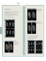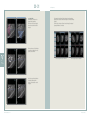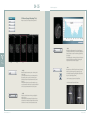
1
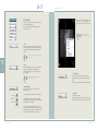
World’s No.1 Dental Digital Radiography & CT
3D Analysis Software
Ez3D
User Manual Version 1.4
Ez3D is a dental imaging software
that assists the dentist to
perform objective diagnosis
and analysis of a patient’s condition
through its 3 dimensional
reconstruction of CT images
in DICOM format
World’s No.1 Dental Digital Radiography & CT
02 > 03
Table of Contents
Table of Contents
Ez3D
User Manual
ATTENTION
Value
Added
Technologies
5
Chapter 1 INTRODUCTION TO Ez3D
6
1.1 Main Functions of Ez3D
7
Chapter 2 INSTALLING, RUNNING AND
REMOVING THE PROGRAM
8
2.1 Minimum System Requirements
2.2 Installation of WIBU Lock Key Driver
2.3 Installation of Ez3D
2.4 Lock Key Setting
2.5 Structure of the Installation Folder
2.6 Removing Ez3D
Ez3D User Manual _ Ver.1.4
8
8
10
12
15
15
Chapter 3 MAIN SCREEN OF Ez3D
16
3.1 Screen Composition
3.1.1 View Mode
3.1.2 Slide Menu
3.1.3 Title Bar
3.1.4 Movement
16
16
18
18
18
3.2 3D and Axial Views
3.2.1 3D View
3.2.2 Axial View
3.3 Coronal View
3.3.1 What is Coronal View?
3.3.2 Axis Adjustment
3.4 Sagittal View
3.4.1 What is Sagittal View?
3.4.2 Axis Adjustment
3.5 Quick Light Boxes(Multi-Slice Views)
3.5.1 Oblique Mode
3.5.2 View Mode
3.5.3 Thickness
3.5.4 Layout Setting
3.6 Panorama View
18
18
20
20
20
20
20
20
20
21
21
22
22
23
24
Chapter 4 ROTATING AXES
25
4.1 Understanding Axes
4.2 Methods of using the Axes
4.2.1 Axial View
4.2.2 Coronal View
4.2.3 Sagittal View
25
26
26
28
30
Chapter 5 SLIDE MENU APPLICATION 32
5.1 View (Image View Tools)
5.2 Measure (Image Measuring Tool)
5.3 Tool/Setting
5.4 Annotate
5.5 Adjust
5.6 Output
32
34
36
39
40
42
Chapter 6 COLOR
46
6.1 Outline
6.2 Color
6.2.1 Transfer Function (Opacity Graph)
Adjustment
6.2.2 Load Color Info (Preset)
6.2.3 Save Color Info (Saving Preset)
6.2.4 Selecting Default Preset
6.3 Windowing
6.3.1 Windowing Bar
46
47
47
50
50
51
51
51
3D Analysis Software
04 > 05
Table of Contents
Value
Added
Technologies
Chapter 7 CURVE USE
53
7.1 Outline
7.2 Curve-Cross Sectional
7.2.1 Creating Curve
7.2.2 Function
53
54
54
54
Chapter 8 DRAWING CANAL
56
Attention
Attention
All software programs and files, data, manual, other documents included in
the Ez3D Product are protected under the Copyright Laws and Computer
Program Protection Law of Korea.
Please refer to the terms of agreement relevant to the use of the product in
the End User License Agreement, which is enclosed along with the product
CD and also appears on the screen at the time of product installation.
For supplementations, this manual is subject to change without prior notice.
8.1 Canal Drawing at the Coronal View
56
8.2 Canal Drawing at the Cross-sectional View 57
Chapter 9 IMPLANT SIMULATION
60
9.1 Outline
9.2 Functions
9.2.1 Implant Insert
9.2.2 Implant Library
9.2.3 Implant Manager
9.2.4 Find Similar Implant
9.2.5 Implant Simulation Check
60
61
61
61
62
63
63
F.A.Q.
64
Copyright
Ez3D User Manual _ Ver.1.4
3D Analysis Software
06 > 07
1
Introduction to Ez3D
Ez3D is a dental imaging software suitable for use on personal
computers that assists the dentist in performing objective diagnosis and
analysis of patients’ conditions by recreating three dimensional CT
images(Computer Tomography) in DICOM format that are stored within
the basic image management software EasyDent. CT images can be
easily analysed using various functions including 3D visualization, Multi
Planar Reconstruction(MPR) and 2D analysis using an easy-to-use
interface.
Value
Added
Technologies
1. Introduction to Ez3D
1.1 Main functions of Ez3D
The main functions of Ez3D are:
> Cross-sectional view obtained by moving the axis on the MPR(Multi Planar Reconstruction).
> Quick and various rendering options such as VR(Volume Rendering)
MIP(Maximum IntensityProjection) and X-Ray.
> An implant simulation tool with which you can preview results of an implant before
the implant is placed.
> An image import function with which you can create a panoramic view of images in order
to compare them at a glance.
Ez3D User Manual _ Ver.1.4
3D Analysis Software
08 > 09
2
2. Installing, Running and Removing the Program
Ez3D Installation File
File Name
Installing, Running
and Removing the Program
Ez3D_Local_Net.exe
Ez3D Local/Network Version Installation file
Automatically transfers to the next screen.
2) Follow the instructions on
the screen which will appear
automatically.
CPU
Intel Pentium4 Dual 3.0GHz or better
Or Intel® Core™2 Duo 2.33 or better
Memory
1GB or better (2GB recommended)
HDD
More than 10G free space (100GB recommended)
Video-card
>
Press Next Button
Select language to use and click ‘Next’
nVidia chipset, 1024x768, 24bpp (1280x1024, 32bpp
or better recommended), 3D Acceleration, 256M
memory or above, Support DirectX9 or above
3) Select a location to install
‘Lock Key Driver’ file and click
‘Next’ button. Files will be
saved at C drive in default.
(nVidia GeForce 8500GT or better recommended)
�On Board Type Graphic Driver can not be used (ex. INTEL on
board type)
OS
Microsoft Windows 2000(SP4)/Windows XP
(SP1) or better
Explorer
Microsoft Internet Explorer 6.0 or better
Etc.
USB port, Mouse, Keyboard, Network card, CDR/RW drive
>
2.2 Installation of WIBU Lock Key Driver
The CD contains ‘WIBU Lock Key Driver’ and ‘Ez3D’ Software.
WIBU Lock Key must be installed first onto the computer before
you start the installation of Ez3D.
Ez3D User Manual _ Ver.1.4
Lock Key Driver file for using WIBU Lock Key
1) Please execute WkRuntime.exe file from among the above
files.
2.1 Minimum System Requirements
Value
Added
Technologies
WkRuntime.exe
4)Select ‘32bit Network
Server’ and ‘Monitor’, then
click ‘Next’.
5) Follow the directions,
clicking the ‘Finish’ button
when prompted which will
complete the installation.
>
3D Analysis Software
10 > 11
2. Installing, Running and Removing the Program
2.3 Installation of Ez3D
If the Lock key driver is installed, please execute Ez3D_Local_Net.exe file
from among the files provided.To exit the installation, click the ‘Exit’ butt0n.
1) Click the ‘Next’ button.
5) Select the optional features that you want to install and then
click ‘Next’ button.
Warning on selecting optional features installation
> Ez3D Local for ATI Graphics Card - Select this if the
graphic card on the PC is manufactured by ATI
> Ez3D CD/DVD Burn Patch for Windows XP SP3 - Select
this if the OS of the PC is XP with Service Pack Version 3
2) Read the End-user License Agreement. Click ‘I accept’ button if you
agree with the terms of the License Agreement.
Then, click ‘Next’ button.
6) Select a drive to install Ez3D, then click ‘Next’ button.
The Program will be installed on C Drive in default.
3) Enter your user and company name, Then click ‘Next’.
7) Click ‘Next’ button to begin Installation.
Value
Added
Technologies
4) Select the set-up version you want to install, then click ‘Next’.
Local version is the version used for an independent PC.
Network version has two types : Console and Workstation. Install Network
Console (for Server) on the PC which is connected to the equipment and
install Network Workstation (for Client) on other PCs. Network Workstation
is a version used on PCs for viewing images within the hospital.
Warning on selecting installation version
The program will not work normally if the program version differs from the
purchased Lock Key. It can be identified by looking at the names on the Lock key.
8) The Progress bar will
appear which displays the
progress of the
installation.
Click the ‘Finish’ button
when prompted to
complete the installation.
> WIBU-BOX/RU+ - Local
> WIBU-BOX/R+ - Network
Ez3D User Manual _ Ver.1.4
3D Analysis Software
12 > 13
2.4 Lock Key Setting
2. Installing, Running and Removing the Program
4) Check only the ‘WkLAN’ from the WIBU-KEY Subsystems,
then enter the Server IP address in the Server Search List box.
Set the environment in the following way when using a
Network Lock Key. Not applicable when using a Local Lock Key.
1) Open ‘Control Panel’ and change to ‘Classic View’ by clicking
‘Switch to Classic View’ if it is currently in ‘Category View’.
2) Set WIBU-KEY and Windows Firewall from the Control Panel.
First, double click on ‘WIBU-KEY’.
5) Register any additional Server IP addresses by clicking the
‘Add’ button.
At this stage please make a note of the number shown in the
WkLAN Port Address window as you will require it later in the
installation process.
Click on ‘OK’ to exit the program.
Value
Added
Technologies
3) Select ‘Network’ among the 4 tabs at the top. Then click ‘OK’.
Ez3D User Manual _ Ver.1.4
6) Now set the Windows Firewall. Select ‘Windows Firewall’
from the Control Panel.
3D Analysis Software
14 > 15
2. Installing, Running and Removing the Program
7) Then select ‘Exceptions’ from the three tabs at the top. Click
‘Add Port’ button.
2.5 Structure of the Installation Folder
The Installation Folder of Ez3D is set as C:\Ez3D by default.
This folder can be changed from the installation screen. If Ez3D
is installed normally, the following folders will be created under
the root folder.
8) Enter the WkLAN Port Address from the Add Port Dialogue
box from the Program Screen of Item (5)(noted from earlier)
and assign the name as Ez3D.
\Exe
Folder containing execution files
\Doc
Storage location for saved documents such as
manuals, etc.
\Captured
Storage location for captured temporary files
\User Settings
Folder containing user setting files
\TmpData
Folder to save temporary files
\Counsel
Folder for saving data temporarily when using
Panorama Import function
\CDViewer
Folder containing CD/DVD Burn Data
Please be cautious not to alter or change the files within each
folder since it may result in an unstable operation of Ez3D.
Value
Added
Technologies
9) Check that the name ‘Ez3D’ is added, then click the ‘OK’
button to complete the settings of the Firewall.
2.6 Removing Ez3D
DICOM image data and user
preset files will not be
automatically removed
even when Ez3D is removed.
This is to protect your data
if Ez3D was removed by
mistake.
Please use Window
Explorer to delete all files.
Ez3D User Manual _ Ver.1.4
The Ez3D software can be removed from your computer in the
following way.
1) Start ‘Control Panel’ from the ‘Start’ menu of Windows.
(For Windows 2000, Start→ Setting → Control Panel).
2) Select ‘Add/Remove Programs’.
3) Select ‘Ez3D’ from the list of currently installed programs,
click the ‘Remove’ button and Ez3D will automatically
removed.
3D Analysis Software
16 > 17
3
3. Main Screen of Ez3D
①
②
③
④
②
①
Main Screen of Ez3D
3D/Axial View
Coronal View
Sagittal View
Multi-Slice Views
③
④
Professional View
①
Value
Added
Technologies
3.1 Screen Composition
②
3.1.1 View Mode
The Basic screen of EZ3D is composed of a
Slide Menu on the left hand side with the
Standard and Professional icons shown at the
top left hand corner.
③
④
⑤
Standard View
Ez3D User Manual _ Ver.1.4
①
②
③
④
⑤
Viewer Mode
Slide Menu
Axial View
Panorama View
Multi-Slice Views
> The Difference between Standard View and
Professional View
Standard View
The screen is composed of Axial, Panorama and Quick Light
Box(Multi-Slice Views). Panorama Importing is possible thus
the overall state of patient’ teeth can be seen in Panorama
View.
Professional View
Screen is composed of 3D, Coronal, Sagittal and Quick Light
Box(Multi-Slice Views). It displays Axial, Coronal and Sagittal
Views as well as a Cross-Sectional View at the bottom.
The 3D View may be substituted with the Axial View.
Anatomical structure of the teeth to be treated can be
examined in detail through implant simulations and various
cross sections. However, Panorama View is not available.
3D Analysis Software
18 > 19
3. Main Screen of Ez3D
Move from Professional to Standard
> Viewer Mode
Changes by selecting icons at the very top.
Move from Standard to Professional
Please refer to ‘Chapter 5
Slide Menu Application’ on
page 32 for details on the
usage of the Slide Menu
tools.
3.1.2 Slide Menu
Basic functions of Ez3D can be easily selected from the Slide
Menu.
3.1.3 Title Bar
Shows the direction of the current cross section image.
Shows reconstructed image in vertical section such as
Axial/Coronal/Sagittal.
3. Main Screen of Ez3D
> Axial
It is possible to toggle the View Mode from 3D to Axial and Axial
to 3D.
> View Mode (Rendering Mode Adjustment)
Selecting ‘View Mode’ on the top right hand corner of the 3D
View will display the following Context Menu.
Select the desired rendering option (X-Ray, VR, or MIP).
X-ray : Refers to an image displayed as X-ray by averaging the
value of transparency on the 3D View.
VR : Refers to displaying the 3D View by rendering with volume.
3.1.4 Movement
Easily move to the next slice or the previous slice by using the
mouse wheel while the cursor is over the image. It performs the
same role as the function of the right-hand side scroll bar.
MIP : Refers to displaying the maximum pixel values within a
specific range at the 3D MPR View.
> Plane (Clipping Plane Mode Setting)
Clicking the 'Plane' button will provide 3 modes of Clipping
Plane, Off/Out-Line/Plane in turn and displays the Plane
Overlay according to each mode on the 3D View. Clipping Plane
is the location of Axial, Coronal, Sagittal on 3D.
Value
Added
Technologies
3.2 3D and Axial Views
3.2.1 3D View
The 3D view is where 3D images can be examined.
> Light (Light Mode Setting)
Light On(-z) / Light On(+z) / Off can be selected by clicking the
‘Light’ Button(Circulating Button).
> Reset
Returns back to the 3D View.
> Expansion Mode
Clicking the Full Screen button will display 3D view in full screen
mode.
Ez3D User Manual _ Ver.1.4
3D Analysis Software
20 > 21
3.2.2 Axial View
> What is Axial View?
Refers to cross-sectional image of the patient in the horizontal
plane viewed from below towards the top.
> Axis Adjustment
Direction of the Axial View can be changed through axial
adjustment in the Sagittal or Coronal view windows.
Please refer to ‘Chapter 4 Rotating Axes’ on page 25
for details on axes adjustment.
The above image displays a crosssection of the Axial View
3. Main Screen of Ez3D
3.5 Quick Light Boxes(Multi-Slice Views)
Quick Light Box(coronal) shows cross-sections at right angles with the vertical axis of the
Axial view and Quick Light Box(sagittal) shows cross-sections at right angles with horizontal
axis of Axial view. Quick Light Box(cross sectional) displays cross-sections at right angles
with a curve plot created from the Axial Viewer.
There are differences as much as the gap between front and back image of Multi Slice View.
Red lined (or Green) image of Axial is displayed in the center. The number of images
displayed on the screen can be changed into 3x1, 5x1, 7x1 by clicking on the Layout button.
> Oblique Mode : Cross-Sectional(coronal), Longitudinal(sagittal)
> View Mode : MPR, MIP
> Thickness : 0, 1, 2, 3, 5 ,10
> Layout : 3x1, 5x1, 7x1
3.3 Coronal View
3.3.1 What is Coronal View?
Refers to a cross-sectional image of the patient in the vertical
plane viewed from the front towards the back.
3.3.2 Axis Adjustment
Direction of Coronal View can be changed through axial
adjustment in the Axial or Sagittal view windows.
Value
Added
Technologies
The image above is a Cross-Sectional, Multi Slice View at 5x1
3.5.1 Oblique Mode
An Oblique Mode allows the user to change the desired image view direction by changing
the Multi -Slice Views into Cross-Sectional(coronal) or Longitudinal(sagittal) views.
The above image shows a crosssection of the Coronal View
3.4 Sagittal View
A Cross-Sectional image squaring with the vertical axis of Axial is called a Coronal Image.
3.4.1 What is Sagittal view?
Refers to a cross-sectional image of the patient in the vertical
plane viewed from left side to right direction.
3.4.2 Axis Adjustment
Direction of the Sagittal View can be changed through axial
adjustment in the Coronal or Axial view windows.
The above image displays a crosssection of the Sagittal view
Ez3D User Manual _ Ver.1.4
Cross-sectional View
3D Analysis Software
22 > 23
A Cross-Sectional image squaring with the horizontal axis of Axial is called a Sagittal image.
3. Main Screen of Ez3D
3.5.4 Layout Setting
The number of Multi-Slice Views can be adjusted at the Context Menu.
Longitudinal View
3.5.2 View Mode
The text displayed as MPR(Multi Planar Reconstruction), MIP(Maximum Intensity
Projection) on the top right hand corner of the cross-sectional image refers to the currently
displayed mode. To change the mode, click the text button to display the following Context
Menu:
3X1
Value
Added
Technologies
A cross sectional image can be examined by selecting the desired rendering mode.
> MPR(Multi Planar Reconstruction) : Refers to displaying each Coronal, Sagittal, Axial
screen according to the viewing direction by reconstructing the 3D image into a 2D black
and white image.
5X1
> MIP(Maximum Intensity Projection) : Refers to displaying the maximum pixel value
within the thickness of 3D MPR Screen.
3.5.3 Thickness
Set thickness by adjusting the thickness value on the top right hand corner of the MPR
image. Click the ‘Thickness’ button to display the following context menu:
7X1
Ez3D User Manual _ Ver.1.4
3D Analysis Software
24 > 25
3.6 Panorama View
It shows a Panoramic View of the patient’s
whole teeth in Standard Mode.
Panoramic images of patients can be
imported using the Panorama Import Tool.
On the Panoramic View, the area of the
patient’s teeth shown on the the
illustration in squre box is for CT imaging.
4. Rotating Axes
4
Rotating Axes
Select the desired image from the
Panorama Import Tool and click ‘Send’ to
display that image on the Panorama View
screen. Panorama Import function is only
available when linked with the EasyDent
program.
4.1 Understanding Axes
Coronal
Sagittal
An Accurate image data of the area requiring treatment can be
obtained by adjusting the axes of the Axial, Sagittal and
Coronal views. The picture explains the concept of Axial,
Coronal and Sagittal views.
> Sagittal means to side cut vertically from left to right
(Color of Axis is yellow)
Value
Added
Technologies
Axial
> Axial means to side cut horizontally from bottom to top
(Color of Axis is Blue)
> Coronal means to side cut vertically from front to back
(Color of Axis is Red)
A section of teeth are displayed by
comparing sectional slices in the Axial,
Coronal and Sagittal views
Axial
Ez3D User Manual _ Ver.1.4
Coronal
Sagittal
3D Analysis Software
26 > 27
4. Rotating Axes
4.2 Methods of using the Axes
Ez3D has a function to rotate axes and adjust the location of axes from each view to examine more accurately
the anatomical structure of the patient.
The Sagittal, Coronal, and Axial are vertically cut in cross-sections regardless of the shape of the dental arch
thus there is limit in clearly understanding the anatomical structure of implants and teeth.
Therefore, accurate measurements of the length of the sections to be treated and detailed anatomical
structure can be obtained through adjustments of the axes.
Axes can be moved by clicking the center
circle in the Axial View and dragging over
onto a specific tooth to examine.
Target
�
Start the explanation by looking at the following Professional View Screen.
Before moving the center circle
After moving the center circle
To rotate the Axis in a desired direction click
the Axis outside of the center circle once
and drag.
Value
Added
Technologies
Before rotating the axes
After rotating the axes
The picture below indicate the other views that have been changed except Axial.
This is because the view directions and angles have been newly adjusted.
The Coronal and Sagittal Views of the teeth can be changed by moving
and adjusting the Coronal and Sagittal Axes.
4.2.1 Axial View
The Coronal and Sagittal Axes can be
adjusted at the Axial View. The direction of
the arrow displayed when the axis is clicked
is the line of the sight.
Before moving, adjusting axes at Axial View
Ez3D User Manual _ Ver.1.4
Aftermoving,adjustingaxesatAxialView
3D Analysis Software
28 > 29
4.2.2 Coronal View
The Axial and Sagittal Axes can be
adjusted at the Coronal View
The direction of the arrow displayed
when the axis is clicked is the line of
sight.
4. Rotating Axes
The Pictures below shows that all other views have been changed with the
exception of the Coronal View. This is because directions and angles of view
have been newly adjusted.
The Axial and Sagittal Views of the teeth can be changed by moving and
adjusting the Axial and Sagittal Axes.
Axes can be moved by clicking the
center circle and dragging over onto a
specific tooth to examine.
Target
Before moving, adjusting axes from Coronal View
After moving, adjusting axes from Coronal View
�
Value
Added
Technologies
Before moving the center circle
After moving the center circle
To rotate the Axis in a desired
direction click the axis outside of
center circle once and drag.
Before rotating the axes
Ez3D User Manual _ Ver.1.4
After rotating the axes
3D Analysis Software
30 > 31
4.2.3 Sagittal View
The Axial and Coronal Axes can be
adjusted at the Sagital View.
The direction of the arrow displayed
when the axis is clicked is the line of
the sight.
4. Rotating Axes
The pictures below indicates all other views have been changed except
Sagittal. This is because the directions and angles of view have been newly
adjusted.
The Axial and Coronal views of the teeth can be changed by moving and
adjusting the Axial and Coronal Axes.
The Axes can be moved by clicking the
center circle and dragging over onto a
specific tooth to examine.
Target
Before moving, adjusting axes from Sagittal View
After moving, adjusting axes from Sagittal View
�
Value
Added
Technologies
Before moving the center circle
After moving the center circle
Possible to rotate in desired direction
to examine by clicking the Axis
outside of the center circle once and
dragging it.
Before rotating the axes
Ez3D User Manual _ Ver.1.4
After rotating the axes
3D Analysis Software
32 > 33
5
5. Slide Menu Application
> Rotate
An Image can be rotated in 2D or 3D.
Click the arrow on the right side of ‘Rotate’ icon and 2D/3D
options will appear.
Select tool and click the left button of the mouse on the image
and drag to a desired direction. Or, click the right mouse button
(
)on the 3D MPR Screen to create Rotate Tool Icon and drag
image to the desired direction.
Slide Menu Application
3D Rotation
> ‘3D Rotation’ enables 3D Rotation within 3D screen and MPR
Screen.
2D Rotation
> Only left and right turn is possible for ‘2D Rotation’.
> Zoom
Selecting this button allows the user to zoom in or out.
Select Zoom and place the cursor over the image. Select and
hold the left mouse button(
) and drag to the left or right,
the image will zoom in or out accordingly.
Tools commonly used throughout Ez3D.
Main tools are located on the left and divided into Text Sections with the
corresponding Icons shown to their right. Any tools with further options
available have an arrow on the right-hand corner of the icon.
Press the arrow to bring up the further options.
Value
Added
Technologies
> Overlay On/Off
> Turns Overlay on or off.
5.1 View (Image View Tools)
The View in the Slide Menu provides basic tools such as Pan,
Rotate, Zoom, Overlay On/Off, and Reset.
Overlay Button Off
Overlay Button On
> Reset
Resets the image. Clicking ‘Reset’ will display ‘Option’.
> ‘Reset All’ will reset the program.
> Pan
Views the image by moving.
After selecting this tool, click left button of the mouse and drag
the image to the desired location. The image can be panned by
dragging the axis in the desired directions.
Ez3D User Manual _ Ver.1.4
Reset all
Auto size
> ‘Auto Size’ will reset the image into an appropriate size to
examine.
3D Analysis Software
34 > 35
5. Slide Menu Application
5.2 Measure (Image Measuring Tools)
Measure is composed of Length, Profile, Angle and Area.
> Angle
Measures the angle between two lines, shown in ‘Degrees’.
Click 'Angle' then click the first point on the image with the left
button then place a second point on the image again clicking
the left button.
This will display a line on the image, then place a third point on
the image which will show a second line on the image, the
angle between the two lines will be displayed.
Value
Added
Technologies
Length
Angle
Area
> Length
Measures distances between two points on the image and is
shown in [mm].
Click ‘Length’ then click the first point on the image with the
left button then place a second point on the image again
clicking the left button. The length between the two points is
displayed.
The measurement line can be moved by moving the mouse
over the measured line until a blue cross appears, then left click
and hold to drag the measurement line to a new position.
> Area
Measures the area of the ROI (Region of Interest) on the image.
Select ‘Area’, click as many points as is necessary to trace
around the ROI ensuring that you finish with a double click at
the point of origin.Displayed in (mm2).
> Line Area creates polygon made of straight lines.
> Curve Area creates a figure made of curves.
> Profile
Pixel values on the line drawn on 2D image are displayed in
graph as in below.
Click between the desired points with the left mouse button
and draw a line. The Density Profile Graph will be created and
both ends can be moved to desired locations using mouse.
Ez3D User Manual _ Ver.1.4
3D Analysis Software
36 > 37
5.3 Tool/Setting
In addition to the tools to assist with diagnosis, there are also
tools for consulting with patients.
Ez3D can be conveniently used by changing the properties
within the Ez3D Program.
5. Slide Menu Application
This is the Implant Insert Menu, clicking the right
mouse button (
) will show submenus
relevant to the Implant, as shown in the picture.
Refer to ‘Chapter 9. Implant
Simulation’ on page 60 for details on
Implants.
> Curve
The Curve tool allows the user to draw a line that follows the
curve of the dental arch which in turn enables the possibility of
creating a Cross Sectional View at right angles to the plotted
curve line.
Refer to ‘Chapter 7. Curve Use’ on page 53 for details
on how to use curves.
> Canal
The canal drawing function adds color to the mandibular canal
and can be a helpful tool when the dentist explains the
relationship between the tooth and the canal to the patient
upon consultation.
Value
Added
Technologies
Canal Drawing is explained in detail on ‘chapter 8.
Drawing Canal’ on page 56
> Panorama Import
Imports panorama images of patients which are saved in
EasytDent. Shows imported panorama images on Panorama
View.
Panorama Import is only available when linked with EasyDent.
> Implant Simulation
User can simulate implant insertion on dental images of
patients before surgery.
Implant Insert
Implant Manager
Implant Library
> Simulate implant insertion on images with ‘Implant Insert’.
> ‘Implant Manager’ shows types and numbers of currently
inserted implants and their characteristics. Show, Hide, Delete
and Alter Implants are also available.
> Information
Shows System Information.
System Information is composed of information on computer
specification, Lock Key information, and program type &version.
> Types of implants per manufacturer can be seen at once
from the ‘Implant Library’, implants may be selected according
to the patients needs. Also, it is possible to list implant models
similar to that of selected implants from the Database.
Ez3D User Manual _ Ver.1.4
3D Analysis Software
38 > 39
> Setting
Displays setting options of each menu on the pop-up windows.
5. Slide Menu Application
[ Common 2]
> MPR Image Magnification : Sets check options that
automatically optimizes the size of an image and zoom rate
when manually setting.
> Default Windowing Value : Default window value selection
option when program begins.
> Light Option : Select the direction of light from screen and
On/Off.
> Screen Capture : Selects whether to save in the database or
as files in the local computer.
[ Common 3]
> Graphic Card Type : Selects the type of video card installed
on the computer.
> Start Layout : Set basic Layout when the program begins.
[Common 1]
� All Thickness : Set the basic thickness at each view screen when the
program starts.
� Volume Processing : Volume Processing is an option for deciding how
many times an image be sharpened or smoothened according to assigned
factor.
The Default Sharp Factor shows the intensity of sharpening and its range
which is between 0~100. The higher the value, the stronger the
sharpness.
Default Smooth Factor shows the intensity of smoothing. Its values ranges
between 0~100. The higher the value, the more intense the smoothness.
Value
Added
Technologies
> Number of Sharp : The Number of Sharps decides how many times it
will sharpen when the program starts.
> Number of Smooth : The Number of Smooth decides how many times it
will smoothen when the program starts.
> Default sharp Factor : Decide on Sharpness.
> Multiple Execution : Set number of programs that can be
executed at the same time.
> Font Size : Decide on the size of font to be used for
Measurements and Annotations.
The changed Option will be applied immediately by
clicking ‘OK’.
5.4 Annotate
Annotation tools are composed of Free Draw, Text, Arrow,
Delete All. It allows users to analyse images easily by marking
key points with lines and memos. i.e. highlighting an area of
interest and making text comments on the image.
> Default smooth Factor : Decide on Smoothness.
> Curve Information : Option to set the distance between each multi-slice
view and thickness of reference position.
> Reference Position : It is an Option for deciding on the interval between
each Multi-Slice View and the thickness of Reference Position.
Ez3D User Manual _ Ver.1.4
> Free Draw
Draw lines on the desired locations on 2D images.
> Text
Write simple texts on the desired locations on 2D images.
3D Analysis Software
40 > 41
> Arrow
Mark parts to emphasize on the images using the Arrow tool.
> Delete All
Deletes all memos on 2D images.
5.5 Adjust
Adjust Tools are composed of Window Adjustment, Color
Conversion, Invert. It allows users to analyse images in detail
since images are processed using these tools.
> Windowing (Width/Level)
Adjust Windowing Width/Level of Window. Select Tool and
dragging left to right by clicking left mouse button will adjust
Width (Contrast: Left-Strong, Right-Weak), dragging top to
bottom will adjust Level (Brightness: Top-Dark, Bottom-Bright).
Value
Added
Technologies
Clicking ‘Windowing’ button will show a
button to activate a dialogue box called
‘Presets’ at the bottom of the MPR Screen.
The Preset Windowing value can be applied
on images by selecting the desired Preset
from this dialogue box. The following
pictures show ‘Windowing Preset’ Dialogue
Boxes.
Ez3D User Manual _ Ver.1.4
5. Slide Menu Application
‘Windowing Preset’ Dialogue Box provides
the following functions.
Default
Set Default Preset
new
Add new Preset Value
Remove
Remove Current Preset Value
Edit
Edit Current Preset Value
OK
Applies Selected Preset on Images
Cancel
Cancels the Operation and Return Back to Screen
Clicking ‘Windowing’ button will show
dropdown combo box menu list next to
‘Preset’ at the bottom of the MPR Screen
that adjusts Windowing Gamma Value.
Windowing Gamma Selection Tool
converts into Gamma Table Value saved in
the images.
> Coloring
Adjust OTF (Opacity Transfer Function) on images. Select the
tool and click left-mouse button from image and dragging left
or right will adjust OTF sections on images.
> Invert
It Inverts all images displayed on the screen. Selecting ‘Invert’
button will invert the images and the status will be maintained
until the button is de-selected.
3D Analysis Software
42 > 43
5. Slide Menu Application
> Sharp
Sharpens all images displayed on the screen.
Sharpness is adjusted in the Setting.
> Smooth
Smoothen all images displayed on the screen by blurring.
Smoothness is adjusted in the Setting.
> Screen capture
Click on the ‘Screen Capture’ tool to capture images by left
clicking on the selected images. It shows saved location at the
time of capturing.
Original Data
With Overlay
�
‘Original Data’ captures only images.
�
‘With Overlay’ captures Overlay and image.
Clicking Screen Capture button will reveal a ‘Full Screen’ button
at the bottom of the screen. Clicking this button will capture the
entire screen.
> Color
Displays tool for adjusting the brightness and contrast of 2D
images and matching volume colors of 3D images at the
bottom.
Captured images can be saved as
image or DICOM files in the desired
location.
Value
Added
Technologies
> Print
Prints the entire image area excluding the tool bar area.
Refer to ‘Chapter 6.
COLOR’ on page 46
for more details.
Clicking ‘Print’ will change the entire screen into Print
Mode. Checking ‘Invert’ at the top of the screen will
invert the colors on the screen and print patient
information at the bottom of the image as well by
checking ‘Patient Information’.
5.6 Output
Capture images and save in file server of a personal computer
or print.
Invert and Patient Information selected Print Screen
Ez3D User Manual _ Ver.1.4
3D Analysis Software
44 > 45
> DVD/CD Burn (DICOM Data Export)
Exports CD Viewer and currently loaded patient’s DICOM Data
using DVD or CD.
Clicking ‘DVD/CD Burn’ at the bottom of the slide menu
will burn Viewer in the DVD/CD which will enable us to
view DICOM Data being used in Ez3D and Data burnt
on CD without Lock Key.
Please insert a blank DVD/CD into the CD drive to burn
Data using the ‘DVD/CD Burn’ function.
Value
Added
Technologies
[Figure 1]
Copies DICOM Data currently shown with a progress
bar
5. Slide Menu Application
[Figure 2-1]
The following DVD/CD Burn window will activate if Data
is copied.
[Figure 2-2]
Select options for burning Data and click ‘Burn’ button.
Clicking ‘Hide’ button will hide the window and will
create a Tray Icon at the right bottom corner of your
screen. Double clicking Tray Icon will reactivate the
window.
[Figure 3]
The progress of DVD/CD Burning can be checked
through the progress bar.
The following message box appears if CD/DVD Burning
has been completed.
Clicking ‘Y’ will end Burning ; selecting ‘N’ will hide the
message box and will go back to [Figure 2] to access
Burn function again.
Ez3D User Manual _ Ver.1.4
3D Analysis Software
46 > 47
6
6.2 Color
The Opacity Graph will be shown at the bottom of the image
when the ‘Color’ button is clicked at the Icon Tool Menu on the
left. Clicking the ‘Color’ button on the right side of the Opacity
Graph area will activate the Color Adjustment Window, and
clicking the ‘Window’ Text Button will activate the Windowing
Adjustment Window.
Click ‘Color’ on the tool menu again to hide the areas of the
Opacity Graph.
This provides the most realistic data to examine the patients
through simulation by adjusting the existing colors or adding
new colors.
Color
6.1 Outline
Opacity adjustment function is available to examine desired
parts of 3D Image Data from the Color Volume Rendering
Screen. The color screen of Ez3D allows various user settings
and possibility to create and save personal preset.
Value
Added
Technologies
6. Color
It is composed of Windowing Bar
to display and adjust the Opacity
Graph (Transfer Function)
indication area and Windowing.
Color and Windowing is converted
by clicking the ‘Convert button’ on
the right.
The Opacity Graph(Transfer Function) is composed of lines
displaying the range of Opacity and adjustment points(square
boxes). If the Opacity Graph(Transfer Function) is changed, the
corresponding Volume Rendering Image and other images will
be freshly updated.
6.2.1 Transfer Function
(Opacity Graph) Adjustment
The following options will appear if
the right mouse button(
) is
clicked on the Opacity Graph.
6.2.1.1 Graph Adjustments
Perform the following tasks to move the graph.
> Graph Movement
The entire graph will move along
the desired direction by clicking
the left mouse button on the blue
adjustment points in the graph
area.
> Adjustment using Graph Adjustment Points
There are six points on the graph, adjusting points 3 and 4 do
not change the slope and are used for adjusting the range of
the graph.
Points 1 and 2 adjust general transparency and area of the
image, Points 5 and 6 at the bottom are used for adjusting the
transparency and area of the graph.
Ez3D User Manual _ Ver.1.4
3D Analysis Software
48 > 49
6.2.1.2 Display area according to the Opacity Graph
(Transfer Function)
Decide the range of the image being displayed on the 3D Screen
by moving the graph area left to right.
As the graph is moved to bigger numbers (2000~4000) only
images of hard calcareous area will remain, as the graph is
moved to smaller numbers (0~-2000) images of soft tissue area
will be shown.
6. Color
> Color Adjustment Point
The Color Adjustment Point is the base location of displaying
colors on the corresponding opacity graph.
One Color Adjustment Point indicates one color, Color-Map
includes the middle color between one color adjustment point
and other color adjustment point.
> Edit Color Adjustment Point
Click the right mouse button(
) on an adjustment point or
click ‘Edit Color’ to display the Color Selection Window again.
Select the desired color and click ‘OK’, this will change the color
on Color Bar and applies it to the 3D Screen.
Value
Added
Technologies
Image viewed by moving the graph towards the
larger numbers(2000~4000)
Image viewed by moving the graph towards
the smaller numbers (0~-2000)
[ Color Bar ]
Adjust the color spectrum corresponding to each value. Move the
location of the square points on the spectrum or activate the popup menu with the right mouse button(
) on the color spectrum
to change the colors.
The Opacity Graph Area(Opacity Filter) can be altered by dragging
the square adjustment points with the mouse.
Each adjustment point has a limit in the direction it can be moved
according to its location, positioning the mouse on the adjusting
points will change the mouse pointer in the form indicating
direction to move.
> Default Range
The following window will activate by clicking the Color Menu
and has the default range values at(-8000~8000). It is possible
to change ranges using the mouse wheel after selecting the
following window. Click the ‘Default Range’ Button to return
back to the default Range.
Use the Color Bar to position the adjustment
points at the desired location for convenient
examination and use by applying to the 3D
Screen.
Color Adjustment Point
Ez3D User Manual _ Ver.1.4
3D Analysis Software
50 > 51
6.2.2 Load Color Info (Preset)
> Importing Preset
Preset refers to preset color values selected by the user to be
applied on the 3D Object Screen. The colors of objects differ
according to the 3D Object.
Clicking right mouse button(
) on areas where the graph is
displayed on the Histogram Screen will activate the following
Options.
New Presets can be imported by using ‘Load Preset’ or ‘Load
Color Info’ from the Option Menu located to the right of color
area.
6. Color
6.2.4 Selecting Default Preset
Default color values on graphs created by adjusting 3D screens
from the Color Bar are saved as image samples using ‘Preset
Save’. When the user selects the desired Preset as the default
Preset of the corresponding Category, the 3D screen that
appears when the program starts will load with the newly
created Default Preset.
> Selecting Default Preset
Click the desired preset thumbnail then check the Default
Opacity box. Click ‘OK’ will assign the currently selected preset
as the default.
6.2.3 Save Color Info (Saving Preset)
Activate the Option Menu by using the ‘Save Color Info’ button
or click right mouse button(
) on the Histogram Screen to
save Opacity Graph setting currently applied on the VR(Volume
Rendering) and the Color Map setting as new Preset file.
Value
Added
Technologies
The following Options will appear when the right mouse button
(
)is clicked from the areas where the graph is displayed on
the Histogram Screen.
The following dialogue box will appear when ‘Save Color Info’ is
selected at the right side of the Color Adjust area or ‘Save
Preset’ from the Options. The New Presets can be added by
using ‘Save Color Info’ button on the right.
6.3 Windowing
Shows a screen for adjusting the window by clicking
‘Windowing Button’ on the right.
Seeks optimum image by looking at the Histogram.
6.3.1 Windowing Bar
Used for adjusting brightness and contrast of the image the
user can adjust the Windowing value that the user is viewing.
Drag by clicking and holding on red or blue
adjustment points as shown.
Clicking ‘Save Color Info’ will capture the 3D Screen in the
current Professional Mode and will be displayed on the
Screenshot.
> Saving Preset
Enter the name of the Preset and click the ‘OK’ button to save,
it can be confirmed by executing Load Color Info on right.
A warning message will appear if the same name exists.
Ez3D User Manual _ Ver.1.4
3D Analysis Software
52 > 53
> Window Center Adjustment
The central value for Windowing is adjusted by dragging the red square adjustment points at the top with left
mouse button(
). Set Brightness of the image by adjusting the blue square adjustment points according to the
location of the central value of the Window.
Low Brightness
Value
Added
Technologies
High Brightness
7. Curve Use
7
Curve Use
7.1 Outline
Curve refers to straight line or curve defined in 3D. Patient’s
dental conditions can be examined in detail using Curve
Function from Ez3D. It is possible to check the status of
continuously created 3D sides in the direction of set location by
setting Path on top of patient’s dental image. Also, Curve can
be altered or edited using pop-up menu.
> Window width adjustment
Adjust by dragging the red square adjustment points at the top of the Line Bar being displayed using the left
mouse button(
).
As the size of Windowing gets bigger(as the distance between the red adjustment points gets wider) contrast will
get lower; reversely, as the size of Windowing gets smaller (as the distance between the red adjustment points
gets narrower) contrast will get higher.
Low Contrast
Ez3D User Manual _ Ver.1.4
High Contrast
3D Analysis Software
54 > 55
7.2 Curve- Cross Sectional
7.2.1 Creating Curve
Set the Path of the Curve by clicking the mouse
from Axial View. Click the left mouse button( )
once from the starting position of Path (if the image
is curve, then creating mid points by clicking left
button in Path will create well-formed curve) and
double clicking or clicking right mouse button( )
once at the finishing point will set the Path of the
Curve.
Multi Slice Views of L(Lingual),
B(Buccal) will be displayed properly
when it is Cross-sectioned from left to
right or from bottom to top
7. Curve Use
> Thickness
The thickness of the slices can be adjusted
from here.
The slices being displayed at the bottom of
the Multi Slice View can be changed by
adjusting the thickness.
> Delete Curve
The path of curve can be deleted from here.
If the curve is set, then vertical cross-section of
the Axial View are displayed on Quick Light
Box(Multi-Slice Views).
Value
Added
Technologies
7.2.2 Function
Open pop-up menu by clicking the right mouse
button(
) from the Axial View. Available
functions include Interval, Thickness and Delete
Curve. It can be viewed by adjusting the values of
vertical sections of the Multi Slice View.
> Interval
The distance between slices on the Curve can be
adjusted from here. The Vertical images being
displayed at the bottom of the Multi Slice View
can be changed by adjusting the distance.
Ez3D User Manual _ Ver.1.4
> Wheel Control
The location of vertical sections being
displayed vertically along the Curve, changes
when the mouse wheel is used on Multi Slice
View image.
> Moving Curve
Can be changed into a desired shape or
moved to a desired location by selecting the
points on the Curve Path from the Axial View.
3D Analysis Software
56 > 57
8
8. Drawing Canal
The canal path can be checked at the Coronal, Sagital,
and Cross-Sectional Views.
Drawing Canal
Ez3D provides an easy way to draw the path of the canal using
Coronal, Sagital, Axial, and Curve-Cross-Sectional Views.
8.1 Canal Drawing at the Coronal View
④
Adjust the axis to show the canal.
At the Main Tool Bar, Select ‘Canal → Canal Insert’.
8.2 Canal Drawing at the Cross-Sectional View
In the Coronal View, draw the path
of the canal by tracing along the
route using the mouse wheel.
Finish setting the path by right
clicking or double clicking the
mouse to enter the final point.
Value
Added
Technologies
①
First, generate a Cross-Sectional View on the image viewer.
The path can be drawn by clicking along the canal route, moving the
Cross-Sectional image, and right clicking or double clicking the mouse
to enter the final point to complete drawing.
> Creating Cross-Sectional
View
Generate Cross-Sectional View,
as shown. Refer to ‘Chapter 7
Curve-Cross-Sectional’.
②
③
Ez3D User Manual _ Ver.1.4
3D Analysis Software
58 > 59
8. Drawing Canal
> Canal Drawing at the Cross-sectional View
At the Cross-Sectional View, choose an image to draw a canal.
At the Main Tool Bar, Select ‘Canal → Canal Insert’.
The canal path can be confirmed, as shown below, when
setting is completed.
At the Coronal View, move the image as
shown below using the mouse wheel and
click to set canal path. Finish setting the path
by right clicking or double clicking the
mouse to enter the final point.
①
④
Value
Added
Technologies
②
> Deletion of canal drawing
At the Main Tool Bar, Select ‘Canal → Canal Delete’. All canals
drawn by the user will be deleted.
③
Ez3D User Manual _ Ver.1.4
3D Analysis Software
60 > 61
9
9. Implant Simulation
9.2 Functions
Implant Simulation
9.2.1 Implant Insert
Insert Implant. Click Tool/Setting → Implant Simulation →
Implant Insert will activate the Implant Library.
Select the desired model and click ‘Insert’ this will change the
cursor into Implant shape, left click on the image to place the
implant at that point.
Or right mouse(
) click on the axis of the Implant currently
selected will also activate the ‘Insert Menu’.
The most recently selected model of Implant from the Implant
Library will be inserted, a default implant will appear if the
Implant Library is not used.
9.1 Outline
The size, location and direction of the Implant that suits the
patient to be treated can be confirmed in advance by inserting
the Implant onto the image.
Select model from Tool/Setting → Implant Simulation →
Implant Library then click ‘Insert’ this will change the mouse
into the shape of Implant.
Click left mouse button(
) at the desired location and place a
cylindrical implant at that location. The types of implant to be
inserted can be selected or replaced from the ‘Implant Library’.
Value
Added
Technologies
9.2.2 Implant Library
Shows lists of implant models saved in the
Database.
New implant models can be registered or
deleted or replaced.
Click Tool/Setting → Implant Simulation →
Library. Or, click ‘Implant Library’ from the
menu activated by clicking the right mouse
button(
).
A window for registering a new implant model will appear when
‘New’ button is clicked from the Implant Library screen.
Enter the length and property and register by clicking ‘Confirm’.
‘Delete’ button will delete the selected Implant Model from the
DB.
‘Modify’ button will change the property of the selected implant
among the implants registered in the DB.
‘Replace’ button will replace the most recently used implant
with an implant selected from the Library.
Ez3D User Manual _ Ver.1.4
3D Analysis Software
62 > 63
9.2.3 Implant Manager
It displays the type, number, and property of
implants currently inserted. It shows hides,
deletes, or replaces implants.
Select Tool/Setting → Implant Simulation →
Implant Manager.
9. Implant Simulation
9.2.4 Find Similar Implant
Its function is to list types of implants similar in
shape to the selected implant by searching
from the Database.
Clicking the right mouse button(
) on the
axis of implant being currently drawn will
activate the ‘Find Similar Implant’ Menu.
It shows whether the current implant is shown
or hidden on the screen. Click ‘Show’ and ‘OK’
buttons to display the selected implant, if the
implant is hidden. Click ‘Hide’ and ‘OK’ buttons
to hide the selected implants from the screen.
Delete selected implants by clicking ‘Remove’
and ‘OK’ buttons. Click ‘Property’ button to
activate the following Implant Property.
Clicking the ‘Replace’ button will change the
implant previously placed into the model from
the list.
9.2.5 Implant Simulation Check
The completed implant can be checked from
the 3D Mode screen.
Value
Added
Technologies
Abutment will be added and the property of Abutment will be shown as
well by clicking the Add Abutment button.
The property of the Implant can be changed by activating the ‘Implant
Library’ window by clicking the ‘Replace’ button.
Ez3D User Manual _ Ver.1.4
3D Analysis Software
64 > 65
F.A.Q.
Appendix
Frequently Asked Questions
Q.
Ez3D displays error message “WIBU not Found”.
Q.
Keyboard is not operating normally.
A.
Copy Proof Hardware Lock Key is missing or not inserted correctly.
Please make sure that Lock Key is correctly inserted.
A.
Please install keyboard driver on computer.
Q.
3D Screen is black.
Q.
Screen does not display properly when Ez3D is started.
A.
A.
Select ‘Properties’ from the desktop by right-clicking the mouse.
Ensure that the screen resolution is set to 1024x768 or better.
(Recommend 1280x1024 or better)
Click 'Light' from the top menu on 3D Window or select Color from the left and
adjust Transfer Function.
Q.
MPR screen is not displaying.
A.
Turn-off hardware accelerator or select Color from left and adjust Windowing.
Q.
An error message appears or the computer crashes when closing Ez3D.
A.
Check the system requirements provided and use or upgrade your computer to at
least the minimum recommended specification.
Q.
I am a laptop computer user. A window called MPR is divided into 4 sections and
abnormally broken.
A.
The laptop computer’s installed graphic card is not supporting the 3D Acceleration
function. Double-click ‘Display Property’ from ‘Control Panel’.
Open the ‘Advanced Setting Window’ from ‘Setting’ by clicking ‘Advanced’ button.
Set hardware acceleration to ‘Minimum’ by clicking on ‘Solve Problem’ tab.
Changing this setting will reduce the refresh rate
Q. Color is not displayed correctly when Ez3D is started.
A.
Value
Added
Technologies
Ez3D User Manual _ Ver.1.4
Select ‘Properties’ from desktop by right-clicking the mouse.
Ensure that the color is set to 24-bit or higher from ‘Settings’.
(Recommend 32bit or better)
Q.
The Operating System needs to be reinstalled, what can I do to retain previously
saved data?
A.
Copy and save of the original data in the folder C:\Ez3D which is the default
installation folder onto a separate backup drive or USB stick. Then reinstall the
Operating System and Ez3D if necessary. Copy the saved data into the same directory.
Q.
A message appears while un-installing the WIBU Key Program which reads:
“C:\Program Files\WIBU-SYSTEMS\System\WibuShellExt.Dll is still in use by
another application”
A.
The message appearing during the un-installing of the WIBU Key Program indicates
that certain files cannot be deleted.
Select 'Ignore' and then click 'OK'. Then reboot the system.
Q.
A message appears when the Implant Library is selected which reads:
“Cannot locate C:\Ez3D\User Setting\implant3d.mDatabase”
A.
A database file has been deleted or is not registered. Un-install Ez3D and reinstall.
Please remember to back up your data
Q. Ez3D operates unstably displaying “error 7 occurred” after running screen saver.
A.
It is caused by the termination of Lock Key process being used by Ez3D from the
current PC’s screen saver mode. The message appears when using power save
mode. The Lock Key program can be normally used again just by clicking ‘Restart’
or ‘Ignore’ but not ‘Stop’ button for the Error message.
3D Analysis Software
66 > 67
U.K.
Thank you for taking the time
to use the Ez3D User’s Manual.
We would appreciate any
feedback or comments you
have about this document.
Please email or phone us with
your comments.
You can reach us at :
Czecho
France
Spain
Head Quarters
Beijing in China
Value
Added
Technologies
Fax > +82-31-8005-7816
Korea
Shanghai in China
Hong Kong
Tel > +82-31-679-2073
Houston in U.S.A.
Email > [email protected]
Branch Offices
Taiwan
U.S.A.
Tel > + 1-281-598-8131
Email > [email protected]
U.K.
Tel > + 44-7506713008
Email > [email protected]
Singapore
France
Tel > + 82-31-679-2063
Email > [email protected]
Spain
Tel > + 34-685-991-481
Email > cdcs97@e- wootech.com
Czecho
Tel >
+ 420-733-654-280
Email > [email protected]
Hong Kong
Tel >
+ 852-27838711
Email > [email protected]
Singapore
Tel >
+ 65-8223-1461
Email > [email protected]
Taiwan
Tel >
+ 886-2-2627-1505
Email > [email protected]
Shanghai in China
Tel >
+ 86-158-006-55-006
Email > [email protected]
Beijing in China
Tel >
+ 86-10-5165-5488
Email > [email protected]
Ez3D User Manual _ Ver.1.4
3D Analysis Software
Copyright © 2008 by VATECH Co., Ltd.
All rights reserved. This document may not be reproduced in any manner without the prior written consent from the Publisher.
This manual only contains the EZ3D user guide. For additional information pertaining to this manual and the product, please contact VATECH at:
Tel > +82-31-899-7979
Fax > +82-31-8005-7816
Email > [email protected]
This printed manual distributed along with the product may not include contents specific to the latest version of the product.
Please refer to the software disk or contact your supplier for the latest version.
VATECH Co., Ltd.
473-4, Yun-Min Bidg, Bora-Dong, Giheung-Gu,
Yongin-Si, Gyeonggi-Do, Republic of Korea
www.vatech.co.kr