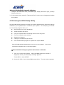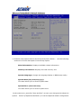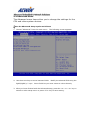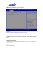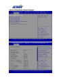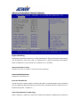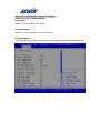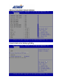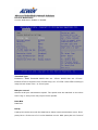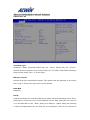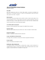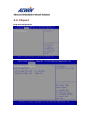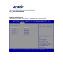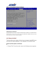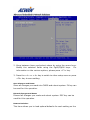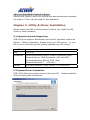
1
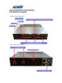
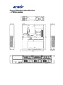
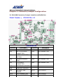
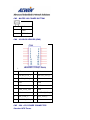
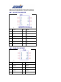
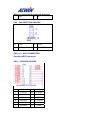
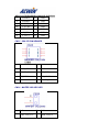
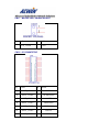
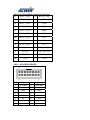
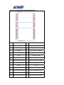
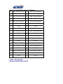
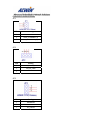
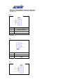
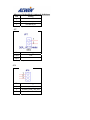
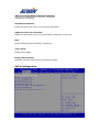
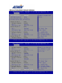
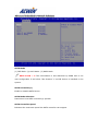
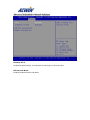
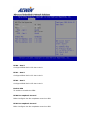
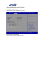
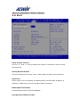
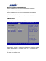
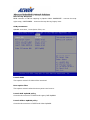
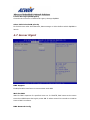
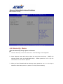
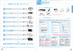
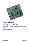
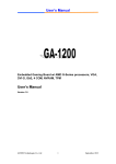
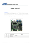
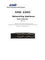
Networking Appliance User’s Manual Version 1.2 SCB-1803 2U Rack-mount Intel® 22nm Haswell Intel® core i3/i5/i7 and E3-1200V3 series with LGA1150 processors and 2 x GbE, SATA, CF, bypass function Reversion History Date Version 2014/02/05 1.0 2014/02/10 1.1 2014/04/02 1.2 Modification Editor First Release Denny Huang 1. Fixed some error information 2. Update R323、R324、R325 Add R318A order information photos Denny Huang Denny Huang © Copyright 2014. All Rights Reserved. This document contains proprietary information protected by copyright. All rights are reserved; no part of this manual may be reproduced, copied, translated or transmitted in any form or by any means without prior written permission of the manufacturer. The content of this document is intended to be accurate and reliable; the original manufacturer assumes no responsibility for any inaccuracies that may be contained in this manual. The original manufacturer reserves the right to make improvements to the products described in this manual at any time without prior notice. Trademarks IBM, EGA, VGA, XT/AT, OS/2 and PS/2 are registered trademarks of International business Machine Corporation Award is a trademark of Award Software International, Inc Intel is a trademark of Intel RTL is a trademark of Realtek VIA is a trademark of VIA Technologies, Inc Microsoft, Windows, Windows NT and MS-DOS are either trademarks or registered trademarks of Microsoft Corporation All other product names mentioned herein are used for identification purpose only and may be trademarks and/or registered trademarks of their respective companies Limitation of Liability While reasonable efforts have been made to ensure the accuracy of this document, the manufacturer and distributor assume no liability resulting from errors or omissions in this document, or from the use of the information contained herein. For more information on SCB-1803 or other AEWIN products, please visit our website http://www.aewin.com.tw. For technical supports or free catalog, please send your inquiry to [email protected] Contents Chapter 1. General Information 1.1 1.2 1.3 1.4 1.5 1.6 1.7 Introducing Specification Order Information Packaging Precautions System Layout Dimension Chapter 2. Connector/Jumper Configuration 2.1 CB-1803 Connector/Jumper Location and Definition Chapter 3. Optional LAN Module and Add-on card 3.1 3.2 3.3 3.4 3.5 R323: Ethernet module with four GbE RJ45 and four SFP GbE R324: Ethernet module with eight GbE SFP R325: Ethernet module with eight GbE Copper R320/R321: 1 PCIe x8 to 3 PCIe x8 in PCIe x16 slot backplane R329: Front I/O Module Chapter 4. BIOS Setup 4.1 4.2 4.3 4.4 4.5 4.6 4.7 4.8 4.9 Quick Setup Entering the CMOS Setup Program Menu Options Advanced Menu Chipset Boot Server Mgmt Security Save & Exit Chapter 5. Utility & Driver Installation 5.1 Operation System Supporting 5.2 System Driver Installation 5.3 LAN Driver Installation Appendix Appendix A: Linux / DOS Sample code Appendix B: Cable Development Kit Chapter 1. General Information 1.1 Introducing The SCB-1803 is a 2U rack-mounted hardware platform designed for network service applications. Built with Intel® Embedded IA components with warranty of longevity, the SCB-1803 Support Single Intel® 22nm Haswell core i3/i5/i7 and E3-1200V3 processors. The platform supports four un-buffered and non-ECC or ECC DDR3 1333/1600 MHz DIMM sockets with max capacity up to 32 GB. In order to provide the best network performance and best utilization, the powerful storage interfaces include one 2.5" SATA HDD and one CompactFlash™. The SCB-1803 also supports one PCIe x4 expansion slot and affords 2 GbE and max 48 GbE Ethernet ports on the front-panel. The front panel also has one USB 2.0 ports, one RJ-45 console port and LED indicators that monitor power and storage device activities for local system management, maintenance and diagnostics. In addition, the SCB-1803 is RoHS, FCC and CE compliant. 1.2 Specification Processor CPU System Memory Intel® Haswell Core i7/i5/i3 and E3-1200V3 Series, LGA1150 Chipset Intel C226 PCH BIOS AMI 64Mbit SPI BIOS Technology Dual-channel, DDR3 1333/1600 MHZ ECC, un-buffered memory or none ECC UDIMM Expansion Capacity up to 32GB Expansion 1.One SO-DIMM slot for IPMI card with VGA Slots support 2.One PCIe x8 slot Ethernet Ethernet R323 : 4 x SFP GbE and 4 RJ45 GbE ports, Intel Modules for Option 82580EB R324 : 8 x SFP GbE ports, Intel 82580EB R325 : 8 x RJ45 GbE ports, Intel 82599ES Hardware Acceleration Module Cryptographic NA Storage SATA HDD One 2.5” SATA HDDs RAID Support Software RAID 0,1,5,10 Compact One CompactFlashTM Type I/II Flash Socket Front USB Port One external USB 2.0 Accessible I/O Console Port One RJ45 Console port (COM1, RS232) Management One GbE port, Intel Port One IPMI port support, Intel i210-IS(Need plug in i211-AT R303) Display Port One VGA pin header via R303(IPMI) (optional) One VGA pin header via processor Power Supply Watt 2U 300W ATX redundant power supply Mechanical and Form Factor 2U rack-mount Environment LCD Module N/A Keypad N/A LED one Power LED (Green) one HDD LED (Yellow) one Status LED (Green/Yellow via programmable GPIO) Dimension(W 426mm (W) x 510mm (D) x 89mm (H) x D x H) (16.77”W x 20.07”D x 3.5”H) Operating Operating: 0 ~ 40°C ( 32 ~ 104°F ) Temperature Storage -20 ~ 75°C (-4 ~ 167°F) Temperature Humidity 10 ~ 85% relative humidity, non-operating, non-condensing Weight 1pc/CTN, 20 kgs Certification CE/FCC 1.3 Order Information SCB-1803A-B 2U Rack-Mount, Intel Haswell processor with C226 PCH, DDR3, 6 PCIe slots for Expansion Module , 1 PCIe x4 slot, Console, USB, 2GbE, SATA, CF R323A R323B Expansion module with 4 x SFP ports and 4 x RJ45 GbE ports, Intel82580EB Expansion module with 4 x SFP ports and 4 x RJ45 GbE ports, Intel82580EB with two pairs bypass function R324A Expansion module with 8 SFP ports, Intel 82580EB R325A Expansion module with 8 RJ45 GbE ports, Intel 82580EB R325B Expansion module with 8 RJ45 GbE ports, Intel 82580EB with four pairs bypass function R303A IPMI card with VGA support R318A PCIe x4 to PCIe x4 Riser card Cable development kit: 46L-CO5204-00 Cross over 2M 46L-DB9200-01 Null modem cable 2M DK002 46L-EC5200-00 Ethernet cat.5 cable 2M 46L-IPS200-00 KBMS cable, 15CM 46L-IUSB2B-00 USB cable, 25CM 46L-IVGA01-00 VGA cable, 20CM 46L-RJDB91-00 RJ-45 to DB-9 cable 2M 1.4 Packaging Please make sure that the following items have been included in the package before installation. 1. SCB-1803 Appliance 2. Cables (Optional) 3. CD-ROM that contains the following folders: 4.1 4.2 4.3 4.4 Manual System Driver Ethernet Driver Utility Tools If any item of above is missing or damaged, please contact your dealer or retailer from whom you purchased the SCB-1803. Keep the box and carton when you probably ship or store SCB-1803 in near future. After you unpack the goods, inspect and make sure the packaging is intact. Do not plug the power adapter to the appliance of SCB-1803 if you already find it appears damaged. Note: Keep the SCB-1803 in the original packaging until you start installation. 1.5 Precautions Please make sure you properly ground yourself before handling the SCB-1803 appliance or other system components. Electrostatic discharge can be easily damage the SCB-1803 appliance. Do not remove the anti-static packing until you are ready to install the SCB-1803 appliance. Ground yourself before removing any system component from it protective anti-static packaging. To ground yourself, grasp the expansion slot covers or other unpainted parts of the computer chassis. Handle the SCB-1803 appliance by its edges and avoid touching the components on it. 1.6 System Layout <Front panel features> <Rear panel features> 1.7 Dimension Chapter 2. Connector/Jumper Configuration 2.1 CB-1803 Connector/Jumper Location and Definition Model Number: CB-1803 Rev.A2 Connector List Connector Description Connector Description CN1 KB/MS PIN HEADER FAN1 FAN CONNECTOR CN2 2X4 +12V POWER CONNECTOR FAN2 FAN CONNECTOR CN3 WAFER 1X2 POWER BUTTOM FAN3 FAN CONNECTOR CN4 VGA BOX HEADER (IPMI) FAN4 FAN CONNECTOR CN5 ATX POWER CONNECTOR FAN5 FAN CONNECTOR CN7 80 PORT PIN HEADER CN8 COM2 BOX HEADER CN9 1X2 RESET PIN HEADER SLOT1 PCIE X4 SLOT CN10 SATA CONNECTOR SLOT2 PCIE X4 SLOT CN11 SATA CONNECTOR DIMM1 IPMI SOCKET CN12 SATA CONNECTOR CN13 SATA CONNECTOR CN14 LCM BOX HEADER CN15 2X4 SPI PIN HEADER CN16 WAFER 1X2 HDD LED CN17 WAFER 1X2 LCM BACKLIGHT CN18 IO CONNECTOR CN19 VGA BOX HEADER CN20 GPI PIN HEADER CN21 PCIE X16 夾板式 CF1 CF SOCKET CONNECTOR CN22 PCIE X16 夾板式 CONNECTOR CN23 PCIE X16 夾板式 CONNECTOR CN24 PCIE X16 夾板式 CONNECTOR CN25 USB2.0 PIN HEADER Jumper List JP1 PCIE CONFIG SELECT JP7 DDR Voltage SEL (PEG) 1-2: Normal (NC) CLOSE: 1.5V 2-3: PEG X8,X4,X4 OPEN: 1.35V JP2 PS-ON SELECT JP8 PLTRST_LAN_I210 1-2: Normal 1-2: PCIE 2-3: Force PS_ON 2-3: NCSI JP3 ATX/AT MODE SELECT JP9 POWER ON/OFF 1-2: ATX MODE CLOSE: RESERVED 2-3: AT MODE OPEN: RESERVED JP4 WDT FOR LAN BY-PASS OR RESET JP10 PCIE SWITCHING 1-2: RESET 1-2: PCIE SWITCHING to R321 2-3: WD_BY# 2-3: PCIE SWITCHING to 1803 JP5 RESERVED JP6 CLEAR CMOS 1-2: Normal 2-3: Clear CMOS Connectors Location & Define CN1 : KB/MS PIN HEADER Pin Define Pin 1 L_KCLK 2 L_MCLK 3 L_KDAT 4 L_MDAT 5 N/A N/A 7 PS2_GND 8 PS2_GND 9 PS2_VCC 10 PS2_VCC 6 Define CN2 : 2X4 +12V POWER CONNECTOR Standard ATX Power CN3 : WAFER 1X2 POWER BUTTOM Pin Define 1 GND 2 SIGNAL CN4 : VGA BOX HEADER (IPMI) 1. Pin Define Pin Define 1 DACRO_VGA_C 2 DACGO_VGA_C 3 DACBO_VGA_C 4 NC 5 GND 6 GND 7 GND 8 GND 9 V5P0_VGA_VIN 10 GND 11 NC 12 DDCDAT_VGA_C 13 HSY_VGA_C 14 VSY_VGA_C 15 DDCCLK_VGA_C 16 NC CN5 : 2X4 +12V POWER CONNECTOR Standard ATX Power CN7 : 80 PORT PIN HEADER 2. Pin Define Pin Define 1 V3P3 2 L_AD0 3 L_AD1 4 L_AD2 5 L_AD3 6 L_FRAME_N 7 PLTRST_IO_N 8 V5P0 9 CLK_33M_PORT80 10 NC 11 GND GND 12 CN8 : COM2 BOX HEADER 3. Pin Define Pin Define 1 DCD#2 6 DSR#2 2 RXD#2 7 RTS#2 3 TXD#2 8 CTS#2 4 DTR#2 9 RIA#2 5 GND 10 NC CN9 : 1X2 RESET PIN HEADER Pin Define Pin Define 1 GND 2 RESET_BTN# CN10~13 : SATA CONNECTOR Standard SATA connector CN14 : LCM BOX HEADER Pin Define Pin Define 1 P-STB# 14 P_AFD# 2 P-PDR0 # 15 P_ERR# 3 P-PDR1 # 16 P_INIT# 4 P-PDR2 # 17 P_SLIN# 5 P-PDR3 # 18 GND 6 P-PDR4 # 19 GND 7 P-PDR5 # 20 GND 8 P-PDR6 # 21 GND 9 P-PDR7 # 22 GND 10 P_ACK# 23 GND 11 P_BUSY 24 GND 12 P_PE 25 GND 13 P_SLCT 26 GND CN15 : 2X4 SPI PIN HEADER Pin Define Pin Define 1 VCC3_SPI 2 GND 3 SPI_CS0_N 4 SPI_CLK 5 SPI_MISO 6 SPI_MOSI 7 NC 8 FLASH_IO CN16 : WAFER 1X2 HDD LED Pin Define Pin Define 1 HDD_LED_VCC 2 HDD_LED_N CN17 : WAFER 1X2 LCM BACKLIGHT Pin Define Pin Define 1 GP74_CONN 2 V5P0 CN18 : IO CONNECTOR Pin Define Pin Define 2 AOUT_CON0+ 1 ALINK100# 4 AOUT_CON0- 3 ALINK1000# 6 AOUT_CON1+ 5 AACT# 8 AOUT_CON1- 7 BINK100# 10 AOUT_CON2+ 9 BINK1000# 12 AOUT_CON2- 11 BACT# 14 AOUT_CON3+ 13 V3P3 16 AOUT_CON3- 15 RTS#1/CTS#1 18 GND_EARTH 17 DTR#1 20 BOUT_CON0+ 19 TXD#1 22 BOUT_CON0- 21 RXD#1 24 BOUT_CON1+ 23 DSR#1 26 BOUT_CON1- 25 -GP70 28 BOUT_CON2+ 27 GP71 30 BOUT_CON2- 29 GP72 32 BOUT_CON3+ 31 GP73 34 BOUT_CON3- 33 HDD_LED_N 36 3VDUAL 35 USB_PP0_CON 38 P80_CTRL 37 USB_PN0_CON 40 V5P0 39 GND CN19 : VGA BOX HEADER Pin Define Pin Define 1 VGA_RED 2 VGA_RED 3 VGA_BLUE 4 NC 5 GND 6 GND 7 GND 8 GND 9 +5V 10 GND 11 NC 12 SDA 13 HSYNC 14 VSYNC 15 SCL 16 NC CN20 : GPI PIN HEADER Pin Define 1 GPIO2 2 GPIO3 3 GPIO4 4 GPIO5 5 GND CN21~24PCIE X16 夾板式 CONNECTOR Standard Aewin PCIE connector CN25 : USB2.0 PIN HEADER Standard USB2.0 connector FAN1~5: FAN CONNECTOR Standard 4 wire fan connector SLOT1: PCIE X4 SLOT Standard PCIE x4 connector SLOT2: PCIE X4 SLOT Pin Define Pin Define B1 GPIO50 A1 EXT_SLOT_FANIN1 B2 GPIO52 A2 EXT_SLOT_FANIN2 B3 GPIO54 A3 EXT_SLOT_FANIN3 B4 GP51 A4 WD_BY#_BUFF B5 GP52 A5 PLTRST_CHIP B6 GP53 A6 GND B7 SMB_DATA_RESUME A7 EXT_CLK_PEG_100MP B8 SMB_CLK_RESUME A8 EXT_CLK_PEG_100MN B9 GND A9 GND B10 EXT_SLOTD_TXP0 A10 EXT_SLOTD_RXP0 B11 EXT_SLOTD_TXN0 A11 EXT_SLOTD_RXN0 B12 B13 GND A12 EXT_SLOTD_TXP1 A13 GND EXT_SLOTD_RXP1 B14 EXT_SLOTD_TXN1 A14 EXT_SLOTD_RXN1 B15 EXT_SLOTD_TXP2 A15 EXT_SLOTD_RXP2 B16 EXT_SLOTD_TXN2 A16 EXT_SLOTD_RXN2 B17 GND A17 GND B18 EXT_SLOTD_TXP3 A18 EXT_SLOTD_RXP3 B19 EXT_SLOTD_TXN3 A19 EXT_SLOTD_RXN3 B20 GND A20 GND B21 EXT_SLOTD_TX4 A21 EXT_SLOTD_RXP4 EXT_SLOTD_TXN4 A22 EXT_SLOTD_RXN4 B22 B23 GND A23 GND B24 EXT_SLOTD_TXP5 A24 EXT_SLOTD_RXP5 B25 EXT_SLOTD_TXN5 A25 EXT_SLOTD_RXN5 B26 GND A26 GND B27 EXT_SLOTD_TXP6 A27 EXT_SLOTD_RXP6 B28 EXT_SLOTD_TXN6 A28 EXT_SLOTD_RXN6 B29 GND A29 GND B30 EXT_SLOTD_TXP7 A30 EXT_SLOTD_RXP7 B31 EXT_SLOTD_TXN7 A31 EXT_SLOTD_RXN B32 GND A32 DIMM1: IPMI SOCKET Standard AeWIN IPMI SOCKET GND Connectors Location & Define JP1 Pin Setting 1 NC 2 HSW_PCUDEBUG_6 3 HSW_PCUDEBUG_6_PL Default (1-2) JP2 Pin Setting 1 IO_PSON#_R 2 FM_PS_ON# 3 GND Default (1-2) JP3 Pin Setting 1 PANSWIN# 2 PSIN 3 AT_PWON Default (1-2) JP4 Pin Setting 1 RESET_WDTO# 2 WDTO# 3 WDTO#_JP4 Default (2-3) JP5 Pin Setting 1 PCH_SRTCRSTB_PULLUP 2 GND Default (NC) JP6 Pin Setting 1 NC 2 PCH_RTCRST_PULLUP 3 RTCRST#_PD Default (1-2) JP7 Pin Setting Close 1.5V Open 1.35V Default (Close) JP8 Pin Setting 1 PLTRST_PCIE_LAN1-2 2 PLTRST_PCIE_LAN_I210 3 Pull down Default (1-2) JP9 Pin Setting 1 GP57# 2 GND Default (NC) JP10 Pin Setting 1 GND (R321) 2 SIO-GP03 3 M2_P45MERGEN (1803) Default (2-3) Chapter 3. Optional Lan Module & Add-on Card Setting The SCB-1803 can offer various GbE and 10GbE module combinations to match various applications and market demand. 3.1 R323: Ethernet module with four GbE RJ45 and four SFP GbE R323 is a four GbE RJ45 and four GbE SFP module. The PCIe x8 golden finger must be connected with CN22、CN23、CN24 or R321A backplane. 3.2 R324: Ethernet module with eight GbE fiber R324 is a eight GbE SFP module. The PCIe x8 golden finger must be connected with CN22、CN23、CN24 or R321A backplane. 3.3 R325: Ethernet module with eight GbE copper R324 is a eight GbE SFP module. The PCIe x8 golden finger must be connected with CN22、CN23、CN24 or R321A backplane. 3.4 R320: Riser Card for R321 R321: 1 PCIe x8 to 3 PCIe x8 in PCIe x16 slot backplane 3.5 R319: Front I/O module R319A is a front I/O module with Power/HDD/Status LEDs, one USB 2.0 port, one RJ45 console port(COM1, RS-232) , two GbE port, The CN1 must be connected to CB-1803. Chapter 4. BIOS Setup The ROM chip of your CB-1803 board is configured with a customized Basic Input/Output System (BIOS) from AMI BIOS. The BIOS is a set of permanently recorded program routines that give the system its fundamental operational characteristics. It also tests the computer and determines how the computer reacts to instructions that are part of programs. The BIOS is made up of code and programs that provide the device-level control for the major I/O devices in the system. It contains a set of routines (called POST, for Power-On Self Test) that check out the system when you turn it on. The BIOS also includes BIOS setup program, so no disk-based setup program is required CMOS RAM stores information for: ●Date and time ●Memory capacity of the appliance ●Type of display adapter installed ●Number and type of disk drives The CMOS memory is maintained by battery installed on the SCB-8970 board. By using the battery, all memory in CMOS can be retained when the system power switch is turned off. The system BIOS also supports easy way to reload the CMOS data when you replace the battery of the battery power lose. 4.1 Quick Setup In most cases, you can quickly configure the system by choosing the following main menu options: 1. Choose “Exit” “Load Optimal Defaults” from the main menu. This loads the setup default values from the BIOS Features Setup and Chipset Features Setup screens. 2. Choose “Main” & “Advanced” from the main menu. This option lets you configure the date and time, hard disk type, floppy disk drive type, primary display and more. 3. In the main menu, press F4 (“Save and Exit”) to save your changes and reboot the system. 4.2 Entering the BIOS Setup Utility Use the BIOS setup program to modify the system parameters to reflect the options installed in your system and to customize your system. For example, you should run the Setup program after you: Received an error code at startup Install another disk drive Use your system after not having used it for a long time Find the original setup missing Replace the battery Change to a different type of CPU Run the AMI Flash program to update the system BIOS Run the BIOS setup program after you turn on the system. On-screen instructions explain how to use the program. Enter the BIOS setup program’s main menu as follows: 1. Turn on or reboot the system. After the BIOS performs a series of diagnostic checks, the following message appears: “Press DEL to enter SETUP” 2. Press the <DEL> key to enter BIOS setup utility. The main menu appears: 3. Choose a setup option with the arrow keys and press <Enter>. See the following sections for a brief description of each setup option. BIOS Information: Displays the BIOS related information. Memory Information: Displays the total memory size. System Language: Change the language display in BIOS setup utility. System Date [Day mm/dd/yyyy]: This item allows you to set the system date. SystemTime: [hour:min:sec]: This item allows you to set the system time. In the main menu, press F4 (“Save and Exit”) to save your changes and reboot the system. Press F3(“Optimized Defaults”) to load the Optimal default configuration values of the menu. Pressing <ESC> anywhere in the program returns you to the main menu. 4.3 Menu Options The main menu options of the BIOS setup program are described in the following and the following sections of this chapter. Main: For changing the basic system configurations. Advanced: For changing the advanced system settings. Chipset: For customize the Intel chipset function Boot: For changing the system boot configurations. Security: For setting User and Supervisor Passwords. Save & Exit: For selecting the exit options and loading default settings. Server Mgmt:For changing the Server Mgmt settings 4.4 Advanced Menu The Advanced menu items allow you to change the settings for the CPU and other system devices. Use the Advanced Setup option as follows: 1. Choose “Advanced” from the main menu. The following screen appears: 2. Use the arrow keys to move between fields. Modify the selected field using the PgUP/PgDN/+/- keys. Some fields let you enter numeric values directly. 3. After you have finished with the Advanced setup, press the <> or <> key to switch to other setup menu or press <F4> key to save setting. PCI Subsystem Settings No Snoop Enables or Disables PCI Express Device No Snoop option. Maximum Payload Set Maximum Payload of PCI Express Device or allow System BIOS to select the value. Maximum Read Request Set Maximum Read Request Size of PCI Express Device or allow System BIOS to select the value. CPU Configuration Hyper-threading Enabled for Windows XP and Linux (OS optimized for Hyper-Threading Technology) and Disabled for other OS (OS not optimized for Hyper-Threading Technology). When Disabled only one thread per enabled core is enabled. Active Processor Cores Number of cores to enable in each processor package. Limit CPUID Maximum Disabled for Windows XP. Execute Disable Bit XD can prevent certain classes of malicious buffer overflow attacks when combined with a supporting OS (Windows Server 2003 SP1, Windows XP SP2, SuSE Linux 9.2, RedHat Enterprise 3 Update 3.) Intel Virtualization Technology When enabled, a VMM can utilize the additional hardware capabilities provided by Vanderpool Technology. Hardware Prefetcher Enable the Mid Level Cache (L2) streamer prefetcher. Adjacent Cache Line Prefetch Enable the Mid Level Cache (L2) prefetching of adjacent cache lines. EIST Enable Enhanced Intel SpeedStep Technology Turbo Mode Enable Turbo Mode Energy Performance Optimize between performance and power savings. SATA Configuration SATA Mode (1) IDE Mode. (2) AHCI Mode. (3) RAID Mode. SATA Port0 ~ 4 This information is auto-detected by BIOS and is not user-configurable. It will show "Not Present” if no IDE device is installed in the system. SATA Controller(s) Enable or disable SATA Device. SATA Mode Selection Determines how SATA controller(s) operate. SATA Controller Speed Indicates the maximum speed the SATA controller can support. RAID0 Enable or disable RAID0 feature. RAID1 Enable or disable RAID1 feature. RAID10 Enable or disable RAID10 feature. RAID5 Enable or disable RAID5 feature. OROM UI and BANNER If enabled, then the OROM UI is shown. Otherwise, no OROM banner or information will be displayed if all disks and RAID volumes are Normal. OROM UI Delay If enabled, indicates the delay of the OROM UI Splash Screen in a normal status. USB Configuration Legacy USB Support Enables Legacy USB support. AUTO option disables legacy support if no USB devices are connected. DISABLE option will keep USB devices available only for EFI applications. USB Mass Storage Device Configuration Configure the USB Mass Storage Devices. USB transfer time-out The time-out value for Control, Bulk, and Interrupt transfers. Device reset time-out USB mass storage device Start Unit command time-out. Device power-up delay Maximum time the device will take before it properly reports itself to the Host Controller. 'Auto' uses default value: for a Root port it is 100 ms, for a Hub port the delay is taken from Hub descriptor. Platform Function SOL Switch Switch console for COM2 or SOL. Watch dog Mode Watch dog Mode(Sec/Min). Watch dog Timer Watch dog Mode(Sec/Min). NCT6791D Super IO Configuration Serial Port 0/1 Configuration Serial Port Enable or Disable Serial Port (COM) Change Settings Select an optimal setting for Super IO device. Pc Health Status This screen shows the motherboard voltage and system temperature. Console Redirection Settings(COM0) Console Redirection Console Redirection Enable or Disable. Terminal Type Emulation: ANSI: Extended ASCII char set. VT100: ASCII char set. VT100+: Extends VT100 to support color, function keys, etc. VT-UTF8: Uses UTF8 encoding to map Unicode chars onto 1 or more bytes. Bits per second Selects serial port transmission speed. The speed must be matched on the other side. Long or noisy lines may require lower speeds. Data Bits Data Bits. Parity A parity bit can be sent with the data bits to detect some transmission errors. Even: parity bit is 0 if the num of 1's in the data bits is even. Odd: parity bit is 0 if num of 1's in the data bits is odd. Mark: parity bit is always 1. Space: Parity bit is always 0. Mark and Space Parity do not allow for error detection. They can be used as an additional data bit. Stop Bits Stop bits indicate the end of a serial data packet. (A start bit indicates the beginning). The standard setting is 1 stop bit. Communication with slow devices may require more than 1 stop bit. Flow Control Flow control can prevent data loss from buffer overflow. When sending data, if the receiving buffers are full, a 'stop' signal can be sent to stop the data flow. Once the buffers are empty, a 'start' signal can be sent to re-start the flow. Hardware flow control uses two wires to send start/stop signals. VT-UTF8 Combo Key Support Enable VT-UTF8 Combination Key Support for ANSI/VT100 terminals. Recorder Mode With this mode enabled only text will be sent. This is to capture Terminal data. Resolution 100x31 Enables or disables extended terminal resolution. Legacy OS Redirection Resolution On Legacy OS, the Number of Rows and Columns supported redirection. Putty KeyPad Select FunctionKey and KeyPad on Putty. Redirection After BIOS POST The Settings specify if BootLoader is selected than Legacy console redirection is disabled before booting to Legacy OS. Default value is Always Enable which means Legaacy console Redirection is enabled for Legacy OS. Serial On Lan Terminal Type Emulation: ANSI: Extended ASCII char set. VT100: ASCII char set. VT100+: Extends VT100 to support color, function keys, etc. VT-UTF8: Uses UTF8 encoding to map Unicode chars onto 1 or more bytes. Bits per second Selects serial port transmission speed. The speed must be matched on the other side. Long or noisy lines may require lower speeds. Data Bits Data Bits Parity A parity bit can be sent with the data bits to detect some transmission errors. Even: parity bit is 0 if the num of 1's in the data bits is even. Odd: parity bit is 0 if num of 1's in the data bits is odd. Mark: parity bit is always 1. Space: Parity bit is always 0. Mark and Space Parity do not allow for error detection. They can be used as an additional data bit. Stop Bits Stop bits indicate the end of a serial data packet. (A start bit indicates the beginning). The standard setting is 1 stop bit. Communication with slow devices may require more than 1 stop bit. Flow Control Flow control can prevent data loss from buffer overflow. When sending data, if the receiving buffers are full, a 'stop' signal can be sent to stop the data flow. Once the buffers are empty, a 'start' signal can be sent to re-start the flow. Hardware flow control uses two wires to send start/stop signals. VT-UTF8 Combo Key Support Enable VT-UTF8 Combination Key Support for ANSI/VT100 terminals. Recorder Mode With this mode enabled only text will be sent. This is to capture Terminal data. Resolution 100x31 Enables or disables extended terminal resolution. Legacy OS Redirection Resolution On Legacy OS, the Number of Rows and Columns supported redirection. Putty KeyPad Select FunctionKey and KeyPad on Putty. Redirection After BIOS POST The Settings specify if BootLoader is selected than Legacy console redirection is disabled before booting to Legacy OS. Default value is Always Enable which means Legaacy console Redirection is enabled for Legacy OS. 4.5 Chipset PCH-IO Configuration SLP_S4 Assertion Width Select a minimum assertion width of the SLP_S4# signal Restore AC Power Loss Select AC power state when power is re-applied after a power failure. Intel(R) VT-d Enable/Disable Intel(R) Virtualization Technology for Directed I/O. Enhance IO Mode Enable/Disable Enhance IO Mode PEG0 - Gen X Configure PEG0 B0:D1:F0 Gen1-Gen3 PEG1 - Gen X Configure PEG1 B0:D1:F1 Gen1-Gen3 PEG2 - Gen X Configure PEG2 B0:D1:F2 Gen1-Gen3 Enable PEG To enable or disable the PEG. PEG0 De-emphasis Control PEG0:Configure the De-emphasis control on PEG PEG1 De-emphasis Control PEG1:Configure the De-emphasis control on PEG PEG2 De-emphasis Control PEG2:Configure the De-emphasis control on PEG Memory Frequency Limitation Maxium Memory Frequency Selections in Mhz 4.6 Boot Setup Prompt Timeout Use the <+> and <-> keys to adjust the number of seconds to wait for setup activation key. Bootup NumLock State This item allows you to select “On” or “Off” power-on state for the NumLock. Quiet Boot If this option is set to Disabled, the BIOS displays normal POST messages. If Enabled, an OEM Logo is shown instead of POST messages. Boot Option Priorities Choose boot priority from boot device. Hard Disk Drive BBS Priorities Specifies the Boot Device Priority sequence from available Hard Drives. CD/DVD ROM Drive BBS Priorities Specifies the Boot Device Priority sequence from available CD/DVD Drives. NETWORK Device BBS Priorities Specifies the Boot Device Priority sequence from available NETWORK Drives. CSM16 Parameters Enable/Disable, Option ROM execution settings, etc. GateA20 Active UPON REQUEST - GA20 can be disabled using BIOS services. ALWAYS - do not allow disabling GA20; this option is useful when any RT code is executed above 1MB. Option ROM Messages Set display mode for Option ROM. INT19 Trap Response BIOS reaction on INT19 trapping by Option ROM: IMMEDIATE - execute the trap right away; POSTPONED - execute the trap during legacy boot. CSM parameters OpROM execution , boot Option filter, etc. Launch CSM This option controls if CSM will be launched. Boot option filter This option controls what devices system can boot to. Launch PXE OpROM policy Controls the execution of UEFI and Legacy PXE OpROM. Launch VIdeo OpROM policy Controls the execution of UEFI and Video OpROM. Launch Storage OpROM policy Controls the execution of UEFI and Legacy Storage OpROM. Other PCI device ROM priority For PCI devices other than Network, Mass storage or Video defines which OpROM to launch 4.7 Server Mgmt BMC Support Enable/Disable interfaces to communicate with BMC Wait For BMC Wait For BMC response for specified time out. In PILOTII, BMC starts at the same time when BIOS starts during AC power ON. It takes around 30 seconds to initialize Host to BMC interfaces. BMC Network Config BMC Network Config 4.8 Security Menu Use the Security Setup option as follows: 1. Choose “Security” from the main menu. The following screen appears: 2. Move between items and select values by using the arrow keys. selected fields using the PgUP/PgDN keys. Modify the Please press the <F1> key for information on the various options. 3. After you have finished with the Security setup, press the <> or <> key to switch to other setup menu or press <F4> key to save setting. Administrator Password: This item allows you to set or change the administrator password. The Administrator Password item on top of the screen shows the default Not Installed. After you have set a password, this item shows Installed. 4.9 Save & Exit The item allows you to save or discard your changes to the BIOS items, and load the optimal defaults or user defaults for the BIOS items. Use the Exit option as follows: 1. Choose “Exit” from the main menu, the following screen appears. 2. Move between items and select values by using the arrow keys. Modify the selected fields using the PgUP/PgDN keys. For information on the various options, please press <F1> key. 3. Press the <> or <> key to switch to other setup menu or press <F4> key to save setting. Save Changes and Reset: Store all changes you made into CMOS and reboot system. F4 key can be used for this operation. Discard Changes and Reset: Discard all changes you made and reboot system. ESC key can be used for this operation. Restore Defaults: This item allows you to load optimal defaults for each setting on the Setup Utility menus, which will provide the best performance settings for system. F3 key can be used for this operation. Chapter 5. Utility & Driver Installation Please install the GbE modules properly before you install the OS, driver or other software. 5.1 Operation System Supporting SCB-1803 can support Windows® and Linux® operation system as follows. Before installation, please check your OS version. If your OS is not in the following list, please upgrade your OS version. OS Version DOS DOS 6.22 Windows® Microsoft Microsoft Microsoft Microsoft Linux® Red Hat Enterprise Linux Server* (x32 and x64) Windows Server 2008R2 Enterprise (x64) Server 2008 Enterprise (x32 and x64) Windows Server 2012 (x64) Windows 7 (x32/x64) 5.2 System Driver Installation SCB-1803 offers the system driver in the setup CD. Please install the driver following the procedures. 5.3 LAN Driver Installation SCB-1803 offers the LAN driver in the setup CD. Please click the Autorun file and install the driver following the procedures. 1. Insert the setup CD of SCB-1803 into your CD-ROM drive. 2. Choose the Drivers file to click the Autorun icon. 3. Follow the procedures to finish the installation. Appendix A: DOS / Linux Sample Code We offer some sample code for SCB-1803 appliance for customer need that sample code is putted into the Driver CD for software development use. Appendix B: Cable Development Kit The SCB-1803 offers some cables for development use. DK002 Item & Description Part No. Qty Ethernet Cat.5 Cable 2M/ RoHS 46L-EC5200-00 1 Cross Over 2M Color/ RoHS 46L-CO5202/4-00 1 RJ45 to DB9 2M Cable/ RoHS 46L-RJDB91-00 1 2m null modem cable/ RoHS 46L-DB9200-01 1 VGA CABLE (2mm) 15CM/ RoHS 46L-IVGA01-00 1 KB/MS CABLE 15CM/ RoHS 46L-IPS200-00 1 USB CABLE/ RoHS 46L-IUSB01-00 1 46L-EC5200-00 46L-DB9200-00 46L-IPS200-00 46L-CO5202/4-00 46L-RJDB91-00 46L-IVGA01-00 46L-IUSB01-00