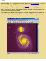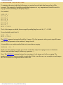
1
Introduction
Version 2.1
(new release 2.1.0 - March 8, 2000 - Updated frequently, consult this page regularly)
Introduction
Settings and running
Other techniques for display an image
Geometry menu
Processing menu
View menu
The right button of the mouse
The Audine camera
LX200
Commands list
Deep-sky preprocessing tutorial
Spectral data preprocessing tutorial
Fast tricolor preprocessing tutorial
Tricolor processing tutorial
Planetary processing tutorial
Buil-Thouvenot Atlas tutorial
Wavelet demonstration
The blink command
Deconvolution tutorial
Astrometry/Photometry tutorial
Mosaic demonstration
Select image command
Report bugs to: [email protected]
Release version 1.1 - Oct. 29, 1999
New commands:
COREGISTER, EXPORT, EXPORTASC, FINDSTAR, IMPORT, IMPORTASC, LOADSB, LOADSX, NEW,
SCALECOLOR, SETFINDSTAR, SETREGISTER, SETSUBSKY
New commands from the View menu: 3D, DDP.
LX200 protocol supported.
file:///C|/help/iris/iris.htm (1 sur 4) [08/03/2000 22:31:22]
Introduction
Release version 1.2.1 - Dec. 12, 1999
New commands:
COPYFWHM, NOFFSET3, PREGISTER, WINDOW3
Bug in ADD3 fixed
Optimization of memory gestion.
Release version 1.2.2 - January, 10, 2000
Bug fixed in EXPORT/IMPORT commands
Bug fixed in Threshold dialog box
Release version 1.2.3 - January, 12, 2000
Specific Windows NT Bug fixed (graphic)
Release version 1.3.1 - January, 18, 2000
Wavelet analysis.
Release version 1.3.2 - January, 28, 2000
Windows NT bug in WAVELET command fixed.
.FTS file bug corrected
Release version 1.4.1 - February, 02, 2000
New commands: BLINK, BLINK2, WAVELET_FILTER, COPYADD, COPYMED, NUMBER.
Version 2.0.0 - February, 24, 2000
New commands: MEM, RL, MOSA, COMPUTE, SKY2REC, REC2SKY
Astrometry/Photometry analysis, Deconvolution, Image selection procedure
Release version 2.1.0 - March, 8, 2000
But corrected in LOADSX command.
New commands: CONVERTSX, SIGNED, PUT, GET, REPAIRX2, REPAIRY2, COPYX, COPYY.
PDF format for the documentation. To view a PDF file, you need a PDF reader such as Adobe™ Acrobat Reader. You can
download Adobe™ Acrobat Reader here.
Iris version 2.1 is a copyrighted freeware. So, Iris version 2.1 is free of all rights for a non commercial
usage and distribution. The software, the demonstration images and related documentation are
exclusively properties of the author.
BT-Atlas © 1994-2000 Christian Buil.
Iris © 1999-2000 Christian Buil.
All rights reserved.
Introduction
Iris is a software written for run under Windows95/98/NT. It offers numerous and powerful functions of
image processing in the field of the digital astronomical images. Iris is particularly optimized to exploit
file:///C|/help/iris/iris.htm (2 sur 4) [08/03/2000 22:31:22]
Introduction
the images that come from CCD cameras. Iris can load and save images in the formats FITS, PIC
(proprietary format), raw or BMP. Iris can read also the images of the Buil-Thouvenot Atlas, a CD-ROM
which contains 4649 images of 6600 objects of the deep-sky.
From the Command window you can execute numerous commands in on-line mode. These commands
are a subset of the commands available in the powerful DOS-32 bits software QMiPS32. The on-line
mode of Iris is extremely practical, notably to make repetitives operations. When you will master it you
will have a powerful productivity tool in hand.
Finally, Iris possesses functions helping the Audine CCD camera construction. The project Audine was
developed by the Association of the Users of Electronic Detectors (AUDE). Iris is a part of this project.
For more information refer to the site of the Audine camera: http://www.astrosurf.org/audine
file:///C|/help/iris/iris.htm (3 sur 4) [08/03/2000 22:31:22]
Introduction
file:///C|/help/iris/iris.htm (4 sur 4) [08/03/2000 22:31:22]
Settings and running
Settings and running
To install Iris decompress ZIP file IRIS.ZIP in the directory of your choice in your hard disk. This
procedure installs also the demonstration image M51.FIT in the hard disk.
From the first run you can use Iris without difficulties. For example, activate the File menu and load the
image M51.FIT in the installation directory of Iris. Then adjust the visualization thresholds.
However, for some applications he will be can be necessary to act on the parameters of the program. One
can for example:
1) Consult data bases on CD-ROM.
2) Work from the Iris command window.
3) Driving the Audine camera.
It is very important to say to Iris where you put your images. This is your working directory. So, during
a first use of Iris you have to make the following operations (Settings…command from the File menu):
1) In the text edit zone Working path enter the complete path of the directory containing your data. For
example: d:\astro (your images are in the directory astro of the disc D:). For the present demonstration,
enter the installation directory of Iris (c:\iris for example).
file:///C|/help/iris/iris1.htm (1 sur 5) [08/03/2000 22:31:32]
Settings and running
2) Select the image files type. You have choice between PIC and FITS format. In this last case a fine
distinction is made between the names of files images ending by the extension FIT or FTS.
3) If the CD-ROM unit chosen by Iris does not agree for you, enter in text edit zone CD-ROM drive unit
the letter of your CD-ROM unity. In the zone BTA catalog path, enter the path of the directory
containing the indispensable catalogs during an exploitation of the BT-Atlas. In the BT-Atlas CD-ROM,
these catalogs are in the CATALOG directory. You can perfectly copy the completeness of this
repertoire in a directory of your hard disk (it is a procedure recommended to read more quickly the data).
In that case you naturally have to change the path the catalogs (for example: c:\catalog\).
4) Click OK.
Execute the Load... command from the File menu and select the M51 file in the Iris directory. The
command we have used had two effects:
(i) transferring the image from the hard drive to the memory,
(ii) displaying the image in memory.
There is a second way to load an image. Click on the Command icon
command:
in the tools bar, then type the
>LOAD M51
Note that the prompt ">" is indispensable left to the key word. Case of letters is not significant.
Press <Enter> to validate your command.
The first word is the command name, and the other one(s) is (are) the command argument(s). Here, the
LOAD command will transfer the chosen image from the drive to the memory. The syntax of this
command is:
LOAD [IMAGE FILE NAME]
IMPORTANT: The default path used by LOAD (and every other command using files) is the Working
path. You may change this path in the Settings window. For example, if you write
C:\ASTRO\MYIMAGES, the images will be automatically loaded from this directory, and saved to it. Of
course, you can also write a complete path when refering to an image (for example LOAD
C:\ASTRO\MYIMAGES\M51). Note that it is not necessary to enter the file extension (.FIT, .FTS,
.PIC...). Also note that the prompt symbol ">" is essential before the command name.
file:///C|/help/iris/iris1.htm (2 sur 5) [08/03/2000 22:31:32]
Settings and running
A command is launched when you type the <Enter> key. It is possible to go back to a previous command
by using the direction key (the cursor position within the line does not matter) and to run it again simply
by pressing the <Enter> key. You can take the opportunity to modify the command parameters. This is
very convenient for operations you want to repeat many times. All the usual edition modes are available
(insert, suppress, copy and paste, ...). Commands are not case sensitive.
Try another command in the command area:
VISU 800 0
VISU is the key command in Iris. It allows you to examine images before and after processing.
Mastering the use of this command is thus essential.
We will simply remind you that visualization consists of displaying each pixel of the image on the screen
with points of varying brightness. In general, the intensity of the point is proportional to the level of the
corresponding pixel in the image.
The levels in the image are constrained by two bounds: the upper threshold that limits the strongest
intensities in the image, and the lower threshold, which limits the weakest intensities. The syntax of the
VISU command is:
VISU [UPPER THRESHOLD] [LOWER THRESHOLD]
The major problem in visualization is that the number of gray levels that can be displayed on the screen
is usually much lower than the number of levels in a digital image. Without preprocessing, it is difficult
to examine all the dynamics of an image with just one visualization. The classical solution is thus to
carry out several visualizations while judiciously choosing the thresholds each time. Type for example:
VISU 6000 0
VISU 12000 0
The galaxy nucleus is now visible. The core itself is saturated in the image and thus cannot be seen no
matter which upper threshold is chosen. Now let's explore the faint regions of the image:
VISU 500 0
VISU 250 50
VISU 50 600
You can now see small, faint galaxies (note the inversion of the thresholds for a negative view).
file:///C|/help/iris/iris1.htm (3 sur 5) [08/03/2000 22:31:32]
Settings and running
There is no attempt to distinguish details within the disk in this last visualization. The aesthetic aspect is
also ignored (the image noise is clearly visible now). The emphasis here is on detectability.
You can easily learn about thresholds by using the two cursors of the Threshold window:
It is easy to modify color palette with the palette selection buttons.
file:///C|/help/iris/iris1.htm (4 sur 5) [08/03/2000 22:31:32]
Settings and running
file:///C|/help/iris/iris1.htm (5 sur 5) [08/03/2000 22:31:32]
Other techniques for display
Other techniques for display an image
With very simple image processing, however, it is possible to get an overall idea of the distribution in one
visualization. To do this, we will calculate the logarithm of the image. The level of the sky background should
be between levels 20 and 50 for optimum efficiency. The BG command tells us that the sky background is
around 134 for the Messier 51 image. We will offset the image by 104, (134-104=30), which brings the level
down enough.
Warning: Since you cannot compute the logarithm of negative numbers, the background sky pixels should not
have a negative value after applying the offset. Otherwise, they cannot be displayed.
Type:
OFFSET -104
LOG 5000
VISU 5000 1500
The above thresholds are characteristic of a logarithmic display.
file:///C|/help/iris/iris2.htm (1 sur 8) [08/03/2000 22:31:41]
Other techniques for display
Save the result (SAVE command):
This command produce the image file I.FIT. Now, note the image dimensions from the Info... command (File
menu):
file:///C|/help/iris/iris2.htm (2 sur 8) [08/03/2000 22:31:41]
Other techniques for display
The image M51.FIT size (or I.FIT size !) is 379 by 466 pixels.
Instead of simply displaying shades of gray, a more quantitative analysis of the information in the image can
be obtained with isophote curves. Try the Isophotes... command from the View menu:
file:///C|/help/iris/iris2.htm (3 sur 8) [08/03/2000 22:31:41]
Other techniques for display
Finaly multiplicate the isophotes curves image by 10 and add the isophotes image and the logarithm image of
Messier 51:
file:///C|/help/iris/iris2.htm (4 sur 8) [08/03/2000 22:31:41]
Other techniques for display
file:///C|/help/iris/iris2.htm (5 sur 8) [08/03/2000 22:31:41]
Other techniques for display
Try another thing. Reload the M51 image, then execute the Modified Equalization from the View menu. All
the parts of the galaxy are now clearly visible.
Iris has a complete 3D visualization possibility. Try for example:
file:///C|/help/iris/iris2.htm (6 sur 8) [08/03/2000 22:31:41]
Other techniques for display
Over aspects of the Iris interface:
file:///C|/help/iris/iris2.htm (7 sur 8) [08/03/2000 22:31:41]
Other techniques for display
file:///C|/help/iris/iris2.htm (8 sur 8) [08/03/2000 22:31:41]
Geometric transforms menu
Geometric transformations menu
RESAMPLE COMMAND
This command can be used to enlarge or reduce the current image. Each axis can have a different scale
factor. The parameters are:
Method = type of interpolation
- Duplication, for an enlargement, interpolation by pixel duplication; for reduction,
interpolation by undersampling
- Bilinear, bilinear interpolation
- Spline, spline interpolation (only for enlargements).
X factor = scale factor along the X axis.
Y factor = scale factor along the Y axis.
The Resample command can be used to detail regions of an image by enlarging them. Reducing images
is also useful when they take up too much space, or to build a library of quick-look images (where only
an approximate look is important). For reducing use factors inferior to unity.
Interpolation by pixel duplication conserves the sharpness of the image, but of course the result has an
artificial look. Bilinear interpolation gives the image a smoother look than simple pixel duplication.
Nevertheless, for large enlargement factors, some artificial geometric structures can appear around stars,
so, spline interpolation is preferable.
WINDOW COMMAND
Creates the output image from a window defined in the input image. The window is here defined with the
2 points: (Xmin; Ymin) & (Xmax, Ymax). The Window command allows you to easily modify the
file:///C|/help/iris/iris3.htm (1 sur 3) [08/03/2000 22:31:46]
Geometric transforms menu
format of an image. These changes are useful when, for example, the region of interest only occupies a
small part of the image. You can then create an image containing only this region, which saves space
and speeds up the calculations.
ROTATE COMMAND
Rotates the current image around the point (X center, Y center) by the angle Degree. The center of the
rotation can be off the screen. Note that the coordinates of this center can be noninteger.
FLIP COMMANDS
Horizontal: Permutes the upper and lower lines of an image.
Vertical: Permutes the right and left columns of an image.
Both: Permutes the lines and column lines of an image.
Remark: you may cancel any processing you have just done by clicking on the undo button in the
toolbar.
file:///C|/help/iris/iris3.htm (2 sur 3) [08/03/2000 22:31:46]
Geometric transforms menu
file:///C|/help/iris/iris3.htm (3 sur 3) [08/03/2000 22:31:46]
Image processing menu
Image processing menu
GAUSSIAN FILTER
Applies a gaussian filter (low-pass).The width of the gaussian used for the convolution is set by the
Sigma parameter value. The convolution of an image by a Gaussian with a small sigma (less than 1) can
be used to attenuate the noise. A high value for sigma produces a fuzzy effect. A Sigma value less than
0.5 has no effect.
ADAPTATIVE FILTER
Adaptively filters noise by using the "Minimum Mean-Square Error" method. The Noise parameter
contains the typical value of noise in the sky background. This value may be obtained after drawing a
rectangle about 30 to 40 pixels in width, avoiding the galaxy and stars, then clicking on the right button
of the mouse and choosing the Statistics command. The noise is given in the standard deviation value
Sigma. You can use also the the in-line command BGNOISE. The Adaptative filter command allows
reduction of noise in the image while preserving fine detail.
UNSHARP MASKING
The unsharp masking is a high-pass filter.The Sigma parameter defines the strength of the filter that is
used to generate the unsharp mask (same as for the gaussian filter). The Coefficient parameter defines the
contrast of the final image. Typical values of Sigma=1 and Coef between 1 and 2. If you don't validate
the Planetary option, a special version of the unsharp masking will be used: it is dedicated to deep-sky
objects and suppresses the negative values and thus reduces the artifacts around bright objects (black
voided rings around stars).
file:///C|/help/iris/iris4.htm (1 sur 4) [08/03/2000 22:31:55]
Image processing menu
OFFSET
Add a constant value (positive or negative) to the current image in memory.
file:///C|/help/iris/iris4.htm (2 sur 4) [08/03/2000 22:31:55]
Image processing menu
MULT
Multiply the current image by a constant value (integer or not).
CLIPMAX
All the pixels with an intensity greater than Old are assigned the value New. The Clipmax command
allows you to control the maximum intensity of the pixels in an image. It can be used, for example,
when pixels with a high intensity may cause a calculation error in certain processes, or when you wish to
reduce a 16 bit image to an 8 bit image.
CLIPMIN
All the pixels with an intensity less than Old are assigned the value New. The Clipmin command is
practical for making the contents of an image strictly positive (Old=0 & New=0).
Remark: you may cancel any processing you have just done by clicking on the undo button in the
toolbar.
file:///C|/help/iris/iris4.htm (3 sur 4) [08/03/2000 22:31:55]
Image processing menu
file:///C|/help/iris/iris4.htm (4 sur 4) [08/03/2000 22:31:55]
View menu
View menu
LOGARITHM
Compute the logarithm of the image in memory. It is a basic command to visualize both high and low levels of the image.
EQUALIZATION
Compute an histogram equalization, that will generally result in enhancing the lowest levels in the image.
MODIFIED EQUALIZATION
This method is dedicated to deep-sky objects and allows their optimal visualization (Gaussian histogram, see An Optimized Stretch for
Deep-Sky Images in CCD Astronomy, Winter 1997, pp. 16-18).
Left, standard image. Right, after Modified Equalization.
DDP
Applies a simple method which modifies the pixel intensity distribution (DDP = Digital Development Process). This distribution is linear
(not modified) below a level and non-linear upper this level. A coefficient parameters adjust the dynamic scale. DDP improves the quality
of visualization (give a photographic aspect).
If I(x,y) is the input image, than the output image is:
I'(x,y) = coefficient * level * {I(x,y)/([I(x,y)] + level)}
The operator [] is the low pass filtering. Iris use for it a gaussian filter of width sigma. If sigma has a non-zero value, the fine details of the
file:///C|/help/iris/iris5.htm (1 sur 8) [08/03/2000 22:32:06]
View menu
image are increased. The typical values for sigma are included between 0.7 and 2.
For more details, see: http://www.asahi-net.or.jp/~rt6k-okn/its98/ddp1.htm
Example(M51.FIT image):
Same result is possible from the in-line commands:
file:///C|/help/iris/iris5.htm (2 sur 8) [08/03/2000 22:32:06]
View menu
RAMP
This method may be used with images having a large dynamic range. The algorithm computes the image modulo (modulo value is given in
a dialog box). This creates ramp effects in the image, which is very efficient with a 'false-colors' palette. Modulo value ranges typically
between 256 and 2048.
ISOPHOTES
Displays an image in the form of isophote curves. The parameters are:
X.Dim & Y.Dim: the width and height of the display in screen pixels. The final dimension is adjusted to obtain square pixel images.
High & Low: the high and low levels between which the isophote curves will be drawn.
Step: the step size between two isophotes.
There are three choices for the type of graph:
- Normal: the isophotes are drawn in white
- False-colors: the isophotes are drawn with the current color palette
- Reinforced: the isophotes are drawn with the current color palette and every Step isophotes is a reinforced white line.
file:///C|/help/iris/iris5.htm (3 sur 8) [08/03/2000 22:32:06]
View menu
NOTE: in astronomical imagery, it is often advantageous to work with an image in a logarithmic scale when drawing isophote curves (see
Logarithm command). This avoids having isophotes too close to each other in the bright parts of the image.
3D DISPLAY
Displays an image in the form of tridimensional plots, with the surface of the image represented in the X-Y plane, and the intensities of the
image plotted along the Z axis. It is possible to examine the image from different points of view.
file:///C|/help/iris/iris5.htm (4 sur 8) [08/03/2000 22:32:06]
View menu
The parameters are:
- X Dim, YDim: The width and height of the output image.
- High, Low: The maximum and minimum intensity thresholds between which the tridimensional plot will be drawn.
- Azimut: The azimuth angle in degrees (for example, if Azimut=0, the image is viewed face on , if Azimut=90, the image is
viewed from the side.
-Elevation: The elevation angle in degrees (for example, if Elevation=0, the image is viewed in profile, if Elevation=90, the
image is viewed from above.
- Step: the step of the mesh along the X and Y axes, in pixels.
- Color option: determines the use of the color palette:
- B/W: plot in monochrome
- False-Colors: plot with the current palette.
- Plotting types:
- Horizontal axis: plot of the tridimensional profiles along the X axis of the image
- Vertical axis: plot of the tridimensional profiles along the Y axis of the image
- Both axes: plot of the tridimensional profiles along the X and Y axes of the image.
Examples:
file:///C|/help/iris/iris5.htm (5 sur 8) [08/03/2000 22:32:06]
View menu
file:///C|/help/iris/iris5.htm (6 sur 8) [08/03/2000 22:32:06]
View menu
3D display of a logarithmic image of M51.
Zoom on a star.
FRAME
draws a frame of intensity Level around the current image with small marks every Step pixels. Tick length is Length pixels. If you choose
Length=0, a simple frame will be drawn around the image.
file:///C|/help/iris/iris5.htm (7 sur 8) [08/03/2000 22:32:06]
View menu
Remark: you may cancel any processing you have just done by clicking on the undo button in the toolbar.
file:///C|/help/iris/iris5.htm (8 sur 8) [08/03/2000 22:32:06]
Mouse
The right button of the mouse
Load an image and drag a window around a star with the left button of the mouse:
Then click on the right button of the mouse. A contextual menu will appear Choose the PSF (Point
Spread Function) command . Iris will return information about the star:
file:///C|/help/iris/iris6.htm (1 sur 3) [08/03/2000 22:32:12]
Mouse
In this dialog box, the following information is given: (X,Y) coordinates of the center of the star,
integrated intensity of the star, background level around the star, and FWHM along both X and Y axes.
Now, drag a new window for example in an empty part of the image. Click on the right button of the
mouse and choose the Statistics option:
Iris will return statistical data about the choosen area. Median is a good indicator of the background
level, whereas Sigma gives you the image noise.
file:///C|/help/iris/iris6.htm (2 sur 3) [08/03/2000 22:32:12]
Mouse
If you choose the Window option in the contextual menu. Iris will create a new image from the chosen
area.
If you choose the Resample option, a dialog box will appear, with several options to resample the chosen
area to a given scale. The Spline option allows you to obtain a very smooth image, whereas the
Duplicate option will yield a pixellized effect. The Scale factor may be non-integer. It may also be lower
than 1 in order to reduce the image size (see also the Resample command in the Geometry menu).
file:///C|/help/iris/iris6.htm (3 sur 3) [08/03/2000 22:32:12]
Audine camera
The Audine camera
Some Iris in-line commands were specially written to facilitate Audine CCD construction. But Iris is
optimised for image processing, he is not nevertheless the ideal companion for your nights of
observations. For it he is by far preferable to use Aud’Ace or Pisco softwares who can be downloaded at
this URL: http://www.astrosurf.org/audine
Before being able to make an image with the Audine camera from Iris you have to configure this last
one. For it, click the Audine camera icon in the the tools bar. The following window appears:
Enter the basic address of your printer port (in hexadecimal form). In the great majority the value is 378.
Choose then the binning factor. Adopt for example binning 2x2 that allows a fast reading.
Select the type of CCD which equips your Audine. (KAF-0400 family or KAF-1600 family).
Finally, you can choose to cut the CCD amplifier supply during the integration time (to eliminate
possible problems of electroluminescence). But it is not an absolute necessity during the first attempts
(see on the Web site of the Audine camera).
The basic command to acquire an image is ACQ followed by the integration time in seconds. For
file:///C|/help/iris/iris7.htm (1 sur 3) [08/03/2000 22:32:17]
Audine camera
example, to make an image with the minimal integration time you can enter:
ACQ 0
For a 10-seconds exposure you will make:
ACQ 10
At the end of the exposure time the image is displayed automaticaly.
Other commands related to Audine:
AMPLI_ON
Turn on the output CCD amplifier.
AMPLI_OFF
Turn off the output CCD amplifier.
OBTU_OFF
Close the obturator.
OFFSET [VALUE]
Add the constant VALUE to all the pixels of the current image.
SET0
This command is used to test the Audine camera. It forces all the parallel port bits to 0.
SET255
This command is used to test the Audine camera. It forces all the parallel port bits to 1.
SETC0
Set to 0 the 4 bits of the camera extension port.
SETC255
Set to 1 the 4 bits of the camera extension port.
TEST1 [NUMBER]
Perform NUMBER cycles of transfer between the image zone and the horizontal register. This function
is used for the purpose of testing the camera.
TEST2 [NUMBER]
Perform NUMBER cycles of fast reading of the camera (no digitization).This function is used for the
purpose of testing the camera.
file:///C|/help/iris/iris7.htm (2 sur 3) [08/03/2000 22:32:17]
Audine camera
file:///C|/help/iris/iris7.htm (3 sur 3) [08/03/2000 22:32:17]
LX200
The LX200 protocol
By clicking the button
in the toolbar:
It is possible to pilot a LX200 telescope from Iris.
To move the LX200 in one of the four directions, first select the motion rate : Guide, Center, Find or
Slew. Then click on one of the direction buttons. To stop the motion, click on center Stop button.
The other method of moving the telescope is GOTO procedure. Enter the RA and DEC coordinates. In
the above example we have:
RA = 12 h 47.7 m
DEC = 30° 23'
Then click on the GOTO button.
For synchronise the telescope mount to the current coordinates, click the Align button.
To get the current coordinates of the telescope click the GET button.
Important: before using the LX200 it is necessary to specify the Com Port from the Settings dialog box
(File menu).
file:///C|/help/iris/iris55.htm (1 sur 2) [08/03/2000 22:32:20]
LX200
file:///C|/help/iris/iris55.htm (2 sur 2) [08/03/2000 22:32:20]
Commands list
Commands list
ADD [NAME]
Add the image in memory to the image designated by NAME on the disk (the image must be in the
current directory).
ADD2 [NAME] [NUMBER]
Adds [number] images in the sequence of images having the generic name [name].
Example
ADD2 I 3
adds the images I1.PIC, I2.PIC & I3.PIC.
ADD3 [NAME] [FWHM] [NUMBER]
When using the command REGISTER with deep-sky images, a file FWHM.LST is created on your hard
drive. In this file, the first column contains an image index and the second one corresponds to the largest
FWHM (along either X or Y axis, whichever is greater) of stars within the image.
Images indexes appears according to increasing FWHMs. So, it is possible to determine the best images
in the series by a simple look at this file. The command ADD3 is essentially the same as ADD2, except
that only the images with FWHM better that [FWHM] will be added. ADD3 uses the file FWHM to do
so. Then you may add only the best images of the series.
Example: ADD3 M51- 1.9 12
AF3 [COEF]
Adaptive filtering of the noise in an image. Adaptive filtering consists of adjusting the strength of the
filter as a function of local statistical criteria. The filter will be most active where the signal to noise ratio
is low. This type of filter reduces the noise while conserving a maximum of details in the image.
The parameter [coef] contains a value that fixes the global strength of the filter. The filter does not act if
[coef]=0, and the filter gets stronger as the value of [coef] increases. Typically, [coef] is between 0.1 and
5.
AF3 uses a zone of 3x3 pixels, centered on the pixel being processed, for the statistical calculation.
See also: AF5, MMSE
The AF3 command is a remarkably effective tool for reducing the noise in an image while preserving a
maximum of details. This command (or AF5) is often chosen for this type of application instead of the
filters whose action is isotropic (like those provided in the GAUSS command).
AF5 [COEF]
Same command as AF3 with a 5x5 array.
BG
Return the background level of the image in memory.
file:///C|/help/iris/iris8.htm (1 sur 28) [08/03/2000 22:32:32]
Commands list
BGNOISE
Return the background noise level.
BLINK [NAME1] [NAME2] [DELAY]
Compares two images by displaying them successively and cyclically on the screen. The names of the
two images are in the parameters [name1] and [name2]. The images may have different sizes. It is
recommended to adjust the dynamic and offset of images to minimize flickering effects between the
images (SCALECOLOR is a good command for this operation).
The blinking time may be adjusted with the [delay] parameter that contains the visualization time of an
image in milliseconds.
During blinking it is possible to adjust visualisation threshold, color palette, use some processing
command like TRANS for register dynamicaly the two images... Processing concern the image [name1].
For example, try the commands:
BLINK M51 M51 200
OFFSET 100
TRANS 1 0
To stop blinking enter the command: BLINKOFF.
The BLINK command is a powerful tool to bring out any difference between two images. It can be used
for many kinds of investigations: detection of supernovae, novae, variable stars, comets, asteroids, etc...
BLINK2 [NAME1] [NAME2] [NAME3] [DELAY]
Same command as BLINK but with 3 images instead of 2 (that allows sometimes better identification of
moving objects).
For example: BLINK2 ASTER1 ASTER2 ASTER3 200
BLINKOFF
Stop the blink mode (see BLINK and BLINK2 commands)
CLIPMAX [OLD] [NEW]
All the pixels with an intensity greater than [old] are assigned the value [new].
See also: CLIPMIN
Examples:
CLIPMAX 200 0
The pixels whose intensity is greater than 200 are assigned the value 0.
CLIPMAX 4095 4095
The pixels with a value over 4095 are set to 4095.
The CLIPMAX command allows you to control the maximum intensity of the pixels in an image. It can
be used, for example, when pixels with a high intensity may cause a calculation error in certain
processes, or when you wish to reduce a 16 bit image to an 8 bit image:
file:///C|/help/iris/iris8.htm (2 sur 28) [08/03/2000 22:32:32]
Commands list
CLIPMIN [OLD] [NEW]
All the pixels with an intensity less than [old] are assigned the value [new].
See also: CLIPMAX
The CLIPMIN command is practical for making the contents of an image strictly positive (try CLIPMIN
0 0)
CFA [R] [G] [B]
Extracts the RGB components from a CCD composed with a Color Filter Array (CFA), like Kodak
KAF-0400C CCD. The Iris CFA command is dedicated to a Bayer array with the following aspect:
GRGR
BGBG
GRGR
BGBG
The coordinates of the first red pixel in the bottom left corner of the image have to be set in the variables
CFAX & CFAY in the IRIS.INI file (this file is located in the windows directory).
COMPOSIT
COMPOSIT is a powerful command to perform automatic combination of a sequence of images that
were registered before. The simplest way to combine the images is of course to add them. COMPOSIT
proceeds in that way, but will reject the pixels that have values significantly bad, i.e. for which the
difference with respect of the mean of the values in all the images is greater that [sigma] times the
standard deviation of the values. Moreover, the process may be iterative: at each iteration, a new analysis
of the pixels statistics is made with the left ones. This method is called sigma-clipping. To be very
efficient, it is necessary to have a large number of images to combine (at least 5). Try [sigma] values
between 1.5 & 5.
The [name] parameter contains the generic name of the sequence, and the [#image] parameter contains
the number of images in the sequence.
Example: COMPOSIT M33- 2.5 2 7
Combines the images M33-1.PIC, M33-2.PIC...M33-7.PIC with a rejection level of 2.5 sigma. Two
iterations are performed.
The COMPOSIT command is a powerful tool that gathers efficiency of the simple addition of images in
terms of signal to noise ratio, and the power of median combination in terms of rejection of aberrant
pixels (cosmic rays, satellites, ...).
COMPUTE
Draw a rectangle around a star with the mouse. Then type COMPUTE. Iris reads the files POLX.LST &
POLY.LST created by Astrometry/Photometry dialog box and returns the equatorial coordinates and the
magnitude of the star. See also: SKY2REC, REC2SKY.
CONVERTSX [IN] [OUT] [NUMBER]
file:///C|/help/iris/iris8.htm (3 sur 28) [08/03/2000 22:32:32]
Commands list
Same as LOADSX, but for an image sequence. [in] and [out] are respectively the generic name ot input
and output images. This function convert unsigned 16 bits image to signed 16 bits image (the native
format for Iris). See also: SIGNED.
COPYADD [IN] [OUT] [NUMBER] [NB_ADD]
This command adds the [nbadd] first images with the generic name [in] and saves the result with the
name [out] with the index 1. Then the result of adding the next [nb_add] images of generic name [in] is
saved with the name [out] with the index 2 and so on up to the image [in] with the index [number]. One
of the interests of this command is that the acquisition time put in the header of the added images is the
barycentre of the individual images. As a consequence the dating accuracy contained in the input images
is transferred to the added images.
COPYMED [IN] [OUT] [NUMBER] [NB_MED]
Same command as COPYADD, but uses median averaging instead of adding the [nb_med] images.
COPYFWHM [IN] [OUT] [FWHM] [NUMBER]
Copy images of the sequence [in] to a new sequence [out], but select only images where the FWHM is
inferior to [fwhm] parameter. The command return the selected image number. It is necessary to apply
before the REGISTER command (see also ADD3). COPYFWHM is perfect for isolate good images,
before compositing for example.
Example: COPYFWHM M51- I 1.6 12
COPYX [X_ORIG] [X_DEST]
Copy the colum of position [x_orig] to the colum [x_dest].
COPYY [Y_ORIG] [Y_DEST]
Copy the line of position [y_orig] to the line [y_dest].
COREGISTER [IN1] [IN2]
Performs geometric transforms on [in2] so that it may be superimposed on [in1]. The output file is the
new [in2] file.
See also: SETFINDSTAR, SETREGISTER.
Example: COREGISTER N266_1 N266_2
DECONVFLAT [COEFFICIENT]
Counter the smearing effect in an image exposed without obturator. [coefficient] is the ratio between the
reading time of a CCD line and the exposure time.
DIV [NAME] [COEFFICIENT]
Divide the image in memory by the image on disk designated by NAME. The resulting image is
multiplied by the value COEFFICIENT.
DIV2 [IN] [OPERAND] [OUT] [COEF] [NUMBER]
Divides a sequence of images having the generic name [in] by the image [operand] and multiplies the
result by [coef] (see also DIV). The [out] parameter is the generic name of the output images. The
number of images to process is [number].
file:///C|/help/iris/iris8.htm (4 sur 28) [08/03/2000 22:32:32]
Commands list
DRIZZLE [NAME] [RESOLUTION] [NUMBER]
This command performs an optimal adding of images as far as resolution is concerned. The principle is
that, at sub-pixel level, shifts between individual input images are nearly randomly distributed. For
example, a star in the first image may be centered perfectly in the middle of a pixel, whereas it will be
across two pixels in the second one, and so on. Since it is easy to know the exact shift between the
images, it is possible to create an output image with a finer sampling, in which resolution may be
increased with respected to each input image. In fact, energy from each input pixel is dropped in the
output image, and the whole processus may be compared to a drizzle...
The DRIZZLE command is adapted to under-sampled images, for example when the telescope focal
length is too short for the pixel size. One may consider that the system is under-sampled when FWHM is
smaller than 2 pixels.
Before using DRIZZLE, it is necessary to know the shift between the images. We suppose that only a
linear translation exists between images (with no distortion and no rotation). The shift values are in the
file SHIFT.LST (to create this file, refer to the command REGISTER). You can also create this file
manually, by measuring the shifts along X & Y individually (the sign convention is image#1 - image#i).
It is important that all the input images are acquired in the same conditions: same exposure time, same
sky background level. If this is not the case, you have to adjust offset and gain prior to use DRIZZLE
(see commands OFFSET and MULT).
The parameters of the command are:
- [name] is the generic name of the input image.
- [resolution] is the over-sampling factor with respect to the input images. A factor or 2 to
2.5 may be considered as a coherent objective when the number of images is between 5 and
10. If the number of images is much larger, this factor may be increased to values as high as
3 or more.
- [number] is the number of images in the sequence. A minimum of 5 images is generally
necessary.
DTRANS [X] [Y]
Select a star in an image by drawing a small rectangle around it with the mouse. Then, the command
DTRANS translates the images with the values:
DX=[x]-XM
DY=[y]-YM
where (XM, YM) is the centroid of the object in the rectangle.
The DTRANS command is very useful the register a sequence of images with respect to a reference star
at coordinates ([x], [y]) in the reference image.
EXPORT [NAME] [HEADER] [BYTE PER PIXEL] [REVERSE]
Exports images in a non standard format. The program writes the header at the beginning of the file,
whose length in bytes should be specified in [header]. This header is filled with zeroes. In the parameter
[BYTE PER PIXEL], you must indicate whether the pixels are coded on one or two bytes. If the coding
file:///C|/help/iris/iris8.htm (5 sur 28) [08/03/2000 22:32:32]
Commands list
is on two bytes, you must also indicate in the parameter [reverse] the order of the bytes in the 16 bit
word. If [reverse]=0, they will be in the INTEL format (most significant/least significant), while if
[reverse]=1, they will be in the MOTOROLA format (least significant/most significant). See also:
IMPORT.
Example: EXPORT FILE.IMG
256
2
0
Converts the image in memory as a free format image with the name FILE.IMG, and with a header
length of 256 bytes and pixels coded on 16 bits in the INTEL format.
EXPORTASC [NAME]
Saves the images with an ASCII format in 3 rows. the two first rows contain the pixel coordinates (origin
at (1,1)), whereas the third row contains the image intensity. Warning: the result file may be very big for
large input images.
See also: IMPORTASC
FILL [VALUE]
Fills the whole current image with pixels having the [value] intensity.
FINDSTAR
Detects stars having a level greater than [sigma] times the level of the sky background noise (see the
SETFINDSTAR command). A file of the type STAR.LST is created on the drive. This file may be edited
(e.g. EDIT command of MS-DOS). It contains parameters about detected stars (position, instrumental
magnitude, FWHM). More precisely for each colon:
* star number,
* X coordinate of the star in the image,
* Y coordinate of the star in the image,
* instrumental magnitude of the star,
* astrometric right ascension (in decimal degrees),
* declination (in decimal degrees),
* true reduced magnitude,
* isolation criteria for the star (1 is the most isolated),
* the FWHM along X & Y.
Note that STAR.LST file is used with automatic astrometry and photometry command. This commands
are added to this present version of IRIS for the moment.
FULL_PR [IN] [OUT] [DARK] [OFFSET] [FLAT] [NB]
Computes the automatic processing of a sequence of [nb] images having the generic name [in], i.e.
subtracts the offset signal, removes the dark current signal, and divides by the flat-field image. The
images are then automatically registered. At last, the images are added.
- The [dark] parameter contains the name of the dark current map (note: this image must not
contain the offset signal).
- The [offset] parameter contains the name of the offset image (or bias image).
- The [flat] parameter contains the name of the flat-field image (note: this image must not
file:///C|/help/iris/iris8.htm (6 sur 28) [08/03/2000 22:32:32]
Commands list
contain the offset signal or the dark current signal).
Example: we want to process a sequence of 3 raw images of the SH2-136 nebula. The image names are
SH136_1.PIC, SH136_2.PIC and SH136_3.PIC. We have also the images OFFSET.PIC, DARK.PIC and
FLAT.PIC. Load the first image in the sequence:
LOAD SH136_1
With the mouse, select a rectangle typically 50 pixel in width with contain only one non-saturated star.
This rectangle will be used for matching the images. Then type:
FULL_PR
SH136_
RESULT
DARK
OFFSET
FLAT
3
The final image is fully preprocessed and corresponds to the combination of the 3 input images (simple
addition).
The FULL_PR command also created 3 images in the current directory : RESULT1, RESULT3 and
RESULT3 in this example). These images are fully preprocessed. So you may choose between several
combination methods. for example, for a simple addition, you will do:
ADD2
RESULT
3
For a median combination, you will type:
SMEDIAN
RESULT
3
And of a sigma-clipping combination, you will do:
COMPOSIT
RESULT
1.5 1 3
You can also use the ADD3 command, that select the finest images for the addition.
FULL_SPEC [IN] [OUT] [DARK] [FLAT] [OFFSET LEVEL] [ANGLE] [FLAG] [LINE WIDTH]
[NUMBER]
Automatic processing of a sequence of spectra. Compute the preprocessing, correct orientation, register
the sequence to the first spectral image, and finaly add the images. IN is the generic name of the input
sequence. OUT is the registered sequence. DARK is the dark current image name. FLAT is the flat-field
image name. OFFSET LEVEL is the mean level of the level. ANGLE is the orientation of the spectra
relative to the horizontal axis. FLAG=0 for a registration with an absorption line and FLAG=1 for a
registration with an emission line. LINE WIDTH is the typical width of the line profile in pixel.
NUMBER is the number of images in the sequence.
First, draw a rectangle in the current image with the mouse around a significant spectral line then run the
command FULL_SPEC
GAUSS [SIGMA]
Convolves the current image by a two-dimensional Gaussian whose width is given by the parameter
[sigma].
The convolution of an image by a Gaussian with a small sigma (less than 1) can be used to attenuate the
noise. A high value for sigma produces a fuzzy effect.
file:///C|/help/iris/iris8.htm (7 sur 28) [08/03/2000 22:32:32]
Commands list
GAUSS2 [SIGMA]
Same command as GAUSS, but the processing is here done for the whole image, including the sides (that
makes this command slower than the GAUSS).
GET [X] [Y]
Returns the intensity of the pixel at coordinates ([x],[y]).
GRADX [OPTION]
Filters the current image with a gradient along the X axis. The option (1 or 2) allows to choose the
orientation of the gradient (left or right). For example:
LOAD M51
GRADX 1
OFFSET 1000
VISU 1200 800
GRADY [OPTION]
Filters the current image with a gradient along the Y axis. The option (1 or 2) allows to choose the
orientation of the gradient (up or down).
GRADX2 [OPTION]
Same command as GRADX, but with a stronger effect.
GRADY2 [OPTION]
Same command as GRADY, but with a stronger effect.
HSI2RGB [H] [S] [I] [R] [G]
The HSI2RGB command converts a color image defined by its color components Hue, Saturation and
Intensity into a trichromatic image in Red, Green, and Blue. The parameters are:
- [h], [s], [i]: the names of the H, S, I components, respectively.
- [r], [g], [b]: the name of the R, G and B components.
See also: RGB2HSI, TRICHRO
INFO
Returns information about current image (size, date/time of exposure, integration time).
IMPORT [NAME] [X] [Y] [HEADER] [#BYTE] [REVERSE]
Imports images with a nonstandard format. The program skips the header at the beginning of the file.
The number of bytes in the header should be specified in the parameter [header]. The [#byte] parameter
indicates whether the pixels are coded on one or two bytes. If the coding is on two bytes, you must
indicate the order of the bytes in the 16 bit word in the parameter [reverse] . If [reverse]=0, they are in
the INTEL format (most significant/least significant), while if [reverse]=1, they are in the MOTOROLA
format (least significant/most significant). Finally, the parameters [x] and [y] contain the image format
in pixels along the X and Y axes, respectively (the X axis is the one which is read more quickly in the
file).
See also: EXPORT
Example: IMPORT EXTERN.IMG
512
file:///C|/help/iris/iris8.htm (8 sur 28) [08/03/2000 22:32:32]
800
256
2
0
Commands list
Imports the image EXTERN.IMG with the following characteristics: pixels coded in 16 bit INTEL
format, 256 byte header, 512x800 format.
IMPORTASC [NAME]
Imports an image that was saved in a 3-row ASCII format. The two first rows contain the pixel
coordinates (origin in (1,1)), whereas the third row contains the pixel intensity. The extension .ASC is
added automaticaly. Note that this file may be very big for large images.
See also: EXPORTASC
Example: IMPORTASC FILE
L_ADD [LINE1] [LINE2]
Computes for each row of the current image the add of lines between [line1] and [line2]. The sum is
maximized to 32767.
The result is represented as a new image with the same width as the input image and 20 identical lines in
height. Each pixel corresponds to the mean of the input lines in the current row.
L_ADD2 [LINE1] [LINE2] [SKY BACKGROUND] [GAIN] [READOUT NOISE]
Same as L_ADD but by taking into account the noise for the calculation of a weight function. SKY
BACKGROUND is the present sky level in ADU (Analog Digital Unit). GAIN is the camera gain (i.e 2
electrons/ADU). READOUT NOISE is the noise of camera in electrons (i.e. 18 electrons).
L_DIV [NAME] [COEF]
Same principle as L_SUB with a division with the line and a [coef] coefficient.
L_EXPAND [HEIGHT]
Creates a new image with [height] identical lines equal to the line obtained with, L_MEDIAN, or
L_ADD.
L_MEDIAN [LINE1] [LINE2]
Same command as L-MEAN except that a median is applied instead of a mean.
L_ORI
Return the orientation of a spectrum relative to the horizontal axis. Draw first a rectangle in the current
image with the mouse around the spectra.
L_PLOT [HEIGHT]
Creates a new image with a plot of the line obtained with L_MEDIAN, or L_ADD. The width of the plot
is the line width, and its height is [height]. This command produce also the ASCII file PLOT.LST.
L_POS [FLAG] [WIDTH]
Compute the position of a spectral line. If FLAG=0 the line is in absorption. If FLAG=1, the line is in
emission. WIDTH is the typical width of the line(FWHM). Select un area around the line with the mouse
then execute L_POS.
L_REGISTER [IN] [OUT] [FLAG] [WIDTH] [NUMBER]
Register a sequence of NUMBER spectral images with the aim of a spectral line. If FLAG=0 the line is
in absorption. If FLAG=1, the line is in emission. WIDTH is the typical width of the line(FWHM).
file:///C|/help/iris/iris8.htm (9 sur 28) [08/03/2000 22:32:32]
Commands list
Select un area around the line with the mouse then execute L_REGISTER.
L_SUB [NAME]
Subtracts from each line of the current image the line in the [name] image obtained with L_MEDIAN, or
L_ADD.
LOAD [NAME]
Load an image in memory from the current directory (defined in the item Current Directory from the
Settings tab – File menu). You can also indicate in which directory to load a particular image by
specifying the full path of the image. For instance: load c:\nuit7\m51
LOADSB [NAME]
Loads an image in CCD SBIG (ST4, ST4X, ST6, ST7, ST8...) format into memory. This command also
accepts compressed format.
Example: LOADSB M51
LOADSX [NAME]
Directly loads a Starlight Xpress FITS format image (.FIT extension). This function convert unsigned 16
bits image to signed 16 bits image (native format of Iris). See also: CONVERTSX, SIGNED.
LOG [NORM]
Calculates the base 10 logarithm of an image where [norm] is a coefficient which adjusts the maximum
dynamics of the output image and Max(imput image) is the intensity of the brightest pixel in the input
image.
The logarithm of an image is used to display the range of intensity levels in one visualization. Often,
during deep sky image processing, the OFFSET command is used first to bring the sky background close
to level 0. The depiction of faint details is then greatly improved.
Let's calculate the logarithm of the image M51.FIT, whose sky background level is around 130:
LOAD M51
OFFSET –100
LOG 1000
VISU 1000 400
With the STAT command, you can verify that there are no pixels with intensities over 1000 in the final
image.
The LOG command allows you to transform the linear intensity scale into a magnitude scale, to within a
constant. This can be very useful in photometry or in various kinds of image representation (for example
isophotes vizualisation).
LRGB [IN_R] [IN_G] [IN_B] [IN_L] [OUT_R] [OUT_G] [OUT_B]
Give tri-color images IN_R, IN_G & IN_B, the program compute the RGB to HSI conversion, then
replace the I image by the IN_L image (luminance image). Finaly, the program perform the HSI to RGB
conversion for producing the output images OUT_R, OUT_G & OUT_B.
See also: RGB2HSI, HSI2RGB, RGB2PCA, PCA2RGB, TRICHRO.
file:///C|/help/iris/iris8.htm (10 sur 28) [08/03/2000 22:32:32]
Commands list
MAX [PIXEL NUMBER]
Draw a rectangle in the current image with the mouse before running that command. This will replace the
[pixel number] brightest pixels of the rectangle by the median value of the remaining pixels (the median
value is computed at each iteration).
This command is good for interactively removing cosmetic artefacts in an image, such as warm pixels.
To remove a single pixel you will type MAX 1. But you may also remove several pixels at a time, and
even remove a star (e.g. MAX 30).
MEDIAN3 [COEF]
Performs median filtering on the current image. The median value of the intensities of the pixels in a 3x3
matrix around a pixel is calculated for each pixel in the image. The corresponding point in the output
image is set to this median value.
[coef] is a parameter that adjusts the strength of the filter (the action of the filter is maximum if [par]=0).
If we number from n=1 to 9 the values of a 3x3 matrix sorted on increasing order, if I(n) represents the
intensity of the points in the matrix and if I0 represents the intensity of the point at the center of the 3x3
matrix, MEDIAN3 performs as follows:
- if the absolute value of (I0 - I(5)) is greater than: [coef]. . (I(8)-I(2)) then the corresponding
pixel I0 in the output image will be given the median value I(5);
- otherwise, the pixel I0 of the output image will keep the value of I0 from the input image.
Median filtering is an excellent tool for eliminating impulse noise in an image (cosmic rays, interference
in one or two pixels, etc.). The original version of the median filter is very energetic. Used without
finesse, this filter may suppress useful information (faint stars) and give an artificial texture to the filtered
image. This is why a weighting factor has been added to the Iris implementation of the median filter. For
images that are not too noisy, the parameter [coef] is typically between 0.80 and 0.99:
MEDIAN5 [COEF]
Same comand as MEDIAN3 but with a 5x5 matrix.
MEM [#ITER]
Deconvolution using a Maximum Entropy Method. The process is iterative and contains [#iter]
iterations. The size of the image must be square and equal to a power of 2 (see WINDOW3 and PADDING
commands). Before running the command, select an isolated star with the mouse. It has to have a good
signal to noise ratio, but not too bright, in order to avoid saturation.
Generally, 15 to 20 iterations are recommended. Try also to have a sky background close to zero (use the
OFFSET command) but strictly positive.
MIN [PIXEL NUMBER]
Same command as MAX, but applies on pixels having a level lower than the median level of the area
(e.g. for removing non active pixels).
MIRRORX
Rotate the image around a vertical axis.
MIRRORY
file:///C|/help/iris/iris8.htm (11 sur 28) [08/03/2000 22:32:32]
Commands list
Rotates the image around an horizontal axis.
MIRRORXY
Invert the X and Y axis.
MMSE [SIGMA]
Filters adaptatively noise by using the "Minimum Mean-Square Error" method. The [sigma] parameter
contains the typical value of noise in the sky background. This value may be obtained for example with
the STAT command. For example, load the M51.PIC image:
LOAD M51
With the mouse, define a rectangle about 30 to 40 pixels in width, avoiding the galaxy and stars. then run
the STAT command (contextual menu). Iris returns a standard deviation around 8 (it is the estimation of
the sky background). Then type:
MMSE 8.0
The MMSE command allows reduction of noise in the image while preserving fine detail.
MOSA [NAME] [DX] [DY] [TYPE]
MOSA allows you to include a set of elementary images in one image. The images are merged two at a
time. The first image is in memory. The second image is designed by the parameter [name].
The shift between two points on the images you want to merge is contained in the variables ([dx],[dy]).
When the two images have points that overlap (which is not required), the value contained in the variable
[type] allows you to choose the state of the overlapping zone in the final image:
· If [type] = 0: the second input image (the name in IN2) overwrites the first input image ( the name in
IN1) unless the pixels in the second input image have the intensity zero. In this case, the values from the
first input image are used.
· If [type] = 1: the first input image overwrites the second input image unless the pixels in the first input
image have zero intensity, in which case the values from the second input image are used.
· If [type] = 2: the pixels in the output image take the maximum value of the pixels from the two input
images.
· If [type] = 3: the pixels in the output image take the minimum value of the pixels from the two input
images.
· If [type] = 4: the pixels in the output image take the average value of the pixels from the two input
images.
· If [type] = 5: a bilinear interpolation is performed on the common parts of the two input images.
The format of the input images can be different.
The MOSA command is used primarily to put together several shots of the same object in order to have a
single image of this object.
file:///C|/help/iris/iris8.htm (12 sur 28) [08/03/2000 22:32:32]
Commands list
MULT [COEF]
Multiply all the current image pixels by the constant COEF.
MULT2 [IN] [OUT] [COEF] [NUMBER]
Multiplies all the pixels of a sequence of images by [coef]. The generic name of the [number] input
images is [in], whereas the generic name of the output images is [out]. Example : MULT2 I J 0.5 7
MODULO [VALUE]
Computes for each pixel the value modulo [value]. The result is the current image in memory. This
command allows to produce some isophote effects that may be useful to visualize images with large
dynamic ranges. Select the false color palette to a better rendering.
NEW [X] [Y]
Creates a new image filled with zeros. The image has a size of [x] . [y].
NGAIN [NORM]
Normalizes the median level of an image to [norm] by multiplying the image by a constant value. This
command is generally used to change the median level of a flat-field image, in order to prepare a median
sum.
NGAIN2 [IN] [OUT] [NORM] [NUMBER]
Normalizes the median level of a sequence of [number] images having a generic name [in] to [norm] by
multiplying each image with a constant value. The generic name of the output images is [out].
NOFFSET [NORM]
Normalizes the median level of an image to [norm] by adding a constant value to the image.
NOFFSET2 [IN] [OUT] [NORM] [NUMBER]
Normalizes the median level of a sequence of [number] images of generic name [in] to [norm] by adding
a constant value to each image. The generic name of the output images is [out].
NOFFSET3 [IN] [OUT] [NORM] [NUMBER]
Normalizes the median background level of a series of [number] images having the generic name [in] to
[norm]. The generic name of the output images is [out]. You have to select the area in which the
background level will be estimated before running the command. Use the mouse for that. This command
is very useful to normalize background levels in a series of planetary images. For example, the
PREGISTERcommand works best when the background level is close to zero, and when the image
background is uniform including near the image edges (windowing is often necessary to avoid edge
effects). So, a typical sequence to register a series of planetary images will be for example:
WINDOW2 JUP I 5 5
NOFFSET3 I J 0 9
PREGISTER J K 256
MULT3 K K .3 9
ADD2 K 9
170 170 9 (in order to supress bad border)
(in order to make zero level background around the planet)
9
(in order to register the images)
(in order to avoid integer overflow when adding the images)
(in order to composite the 9 images)
NUMBER [GENERIC NAME]
Return the number of images of an image sequence. For example, if the sequence is M31_1.FIT,
file:///C|/help/iris/iris8.htm (13 sur 28) [08/03/2000 22:32:32]
Commands list
M31_2.FIT and M31_3.FIT, NUMBER M31_ return 3.
OFFSET [VALUE]
Adds the constant [value] to the current image. The constant can have a negative value.
OFFSET2 [IN] [OUT] [OFFSET] [NUMBER]
Adds the value [offset] to [number] images having the generic name [in]. The parameter [out] contains
the generic name of the output images.
OPT [DARK FRAME NAME]
In long exposure CCD imagery, one of the major difficulties posed during preprocessing is the dark
current correction. This interference signal, due to thermal charges, is added to the signal produced by
the observed objects. The problem is to suppress this interfering component of the image because it is
noise that impairs the detectability.
A classic solution is to take an exposure of the object under study with an integration time T, then to take
another exposure of length T while placing the detector in total darkness. This last exposure is called the
dark current map. This map is a constant, to within a coefficient, for a given CCD. To first order, the
coefficient is proportional to the temperature of the CCD and to the integration time. In the preceding
procedure, the dark current map is simply subtracted from the image of the object.
This is, however, far from the ideal solution. In fact, this procedure implies that a dark current map must
be taken after each image of the object. This is very constraining when the exposure time is several
minutes or more.
Things seem to go better if the temperature of the CCD is perfectly stable. In this case, a priori only one
map is necessary. It can be taken, for example, at the beginning of the observing session, and can be used
to correct all the images. If the exposure time is not the same on the dark map and the image to be
processed, the dark map must be multiplied by a coefficient before the subtraction. The coefficient is the
ratio of the exposure time of the image to the exposure time of the dark map.
Besides the fact that is a delicate matter to maintain the detector at a fixed temperature, this method has
the following inconvenience - the dark map has its own noise (readout noise) and when the map is
subtracted from the images, this noise is actually added to the images.
There is a more efficient method:
- Take several (5 to 10) dark images with integration times that are not necessarily equal, but
long enough to be sensitive to the dark current (they should have the same duration as the
observation exposures). The CCD should be cooled to reduce the readout noise as much as
possible.
- For each exposure in darkness, another one with a minimal integration time is taken. This
provides the offset map.
- For each of the dark images, subtract the corresponding offset map. The resulting images
then contain only the thermal component of the signal.
-Sum all the images from the previous step to obtain the dark map. This adds the thermal
contributions from each image, but averages the readout noise. This map can be considered
file:///C|/help/iris/iris8.htm (14 sur 28) [08/03/2000 22:32:32]
Commands list
constant for a given CCD (it is still good to redo this procedure every 1 or 2 months to allow
for any possible change in the electronic characteristics of the detector).
- Now a given image must be corrected. The difficulty is in finding a multiplicative
coefficient, to apply to the dark map, which will optimally correct this image. This is what
the command OPT does.
Iris solves this problem nearly instantaneously using an analytical approach.
You have to select an area typically 30 to 100 pixels in width with the mouse. Then run the command.
[dark frame name] is the name of the dark current map. The program will return the coefficient to apply
to the dark current map to create a new map that is optimal for the image to process.
Example: OPT DARK calculates the optimal coefficient for the dark map DARK.PIC to correct the
current image.
The OPT command should be systematically used to preprocess deep sky images. With this command in
hand, you do not need to worry about taking dark images during the night. The result is quite good
because the criteria chosen minimize the noise.
OPT2 [IN] [DARK] [OUT] [NUMBER]
Same command as OPT but applies on a sequence of [number] images having the generic name [in].
[out] is the generic name of the output images.
OPT3 [IN] [DARK] [OUT] [NUMBER]
Same command as OPT2 the with a more fully procedure (it is not necessary to select a zone in the
image).
PADDING [LX] [LY]
Sets the size of the current image to [lx], [ly]. If the image is larger than ([lx], [ly]), it is truncated. If the
image is smaller than ([lx], [ly]), it is completed by pixels of zero intensity.
This command is generally useful for comparing images taking with differents CCD or before using
commands that perform Fast Fourier Transforms for which the image must have a size equal to a power
of 2. For example, the command:
PADDING 256 256
guarantees that the image in memory has a size of 256x256 pixels.
PCA2RGB [C1] [C2] [C3] [R] [G] [B]
The PCIA2RGB command performs the reverse transformation of the RGB2PCA command, that is, it
goes from the space of the principal components to the space of the fundamental colors (R,G,B). To do
this, this function needs the file containing the matrix of the eigenvectors of the covariance matrix of the
three initial trichromatic images (pci.lst). For more information on this technique, see the RGB2PCA
command.
PHOT [RADIUS1] [RADIUS2] [RADIUS3] [OPTION]
Computes aperture photometry. After running the command, one or several circles appear in the field. By
centering the circles on the stars and then clicking on the left button of the mouse the program returns
information about the star intensity.
file:///C|/help/iris/iris8.htm (15 sur 28) [08/03/2000 22:32:32]
Commands list
If [option]=1, a simple circle appears.The returned information is the sum of the intensitites of the pixels
inside the circle (i.e. the sum of the star intensity and the sky background).
If [option]=2, two circles appear. The signal of the star plus the sky background is integrated in the inner
circle. In the area between the two circles, the mean sky background is measured. PHOT then returns the
signal of the star alone (sum of the intensities I, and instrumental magnitude M). The inner circle radius
is [radius1], and the outer circle radius is [radius2].
If [option]=3, three circles appear. The most outer circle radius is [radius3]. It is the same method as
previously, except that the backgroung level is calculated from the area between circles 2 & 3. This
allows sometimes to avoid close stars to the measured star, that may bias the measure of the sky
background.
To exit the PHOT mode, execute the commande PHOTOFF.
Examples:
PHOT 6 0 0 1
PHOT 6 11 18 3
Note: it is important that a rather large number of pixels are used to determine the sky background.
Moreover, as far as the inner circle is concerned, it has to be large enough to contain the whole star, but
not too big in order to minimize noise level.
PHOTM [RADIUS1] [RADIUS2] [RADIUS3] [OPTION]
This command is close to the PHOT command. The difference is that a median is used to compute the
sky background level instead of a simple average. It may be useful to minimize the effect of feeble stars
in the measure annulus. To exit the PHOT mode, execute the commande PHOTOFF.
PR [INPUT] [DARK + OFFSET] [FLAT] [OUTPUT] [NUMBER]
The PR command (PR=PreProcessing) is an important command for the preprocessing of a sequence of
[number] images. The [input] parameter contains the generic name of the images to process. [dark +
offset] is the name of sum of the dark current image and of the offset signal. So, the dark image has
either to be obtained in the same conditions as the images themselves (same exposure time, same
temperature), or to be computed (see the OPT command). [flat] contains the flat-field image. [output] is
the generic name of the output images. See also: FULL_PR
The command PR produce preprocessed images that may be, for example, combined later after
registration (see REGISTER, ADD2, ADD3, DRIZZLE, COMPOSIT, SMEDIAN commands).
PREGISTER [IN] [OUT] [SIZE] [NUMBER]
Performs the registration of [number] planetary images having the generic name [in] using an
intercorrelation method. The size for the intercorrelation is given by [size]. It must be a power of 2 (128,
256, 512...). The size should be larger than the planet diameter. [out] is the generic name of the output
images. Before use PREGISTER define a selection rectangle around the planetary disk (drag with the
mouse). Note that the size of rectangle is not important (the rectangle mark only the center of interest of
the image).
Example: PREGISTER MARS I 256 7
file:///C|/help/iris/iris8.htm (16 sur 28) [08/03/2000 22:32:32]
Commands list
To verify the efficiency of this command, you may subtract an image from another one, e.g.:
LOAD I1
SUB I3 2000
VISU 3000 1000
The observed residuals mainly come from the atmospheric turbulence.
See also : NOFFSET3
PROD [NAME] [COEF]
Performs the multiplication pixel by pixel of the current image by the image [name]. The result is
muliplied by [coef]
Example: To calculate the square of the image M51.PIC:
LOAD M51
PROD M51 .05
VISU 10000 0
PUT [X] [Y] [V]
Attributes the intensity [v] to the pixel at coordinates ([x], [y]). See also: GET
REC2SKY [X] [Y]
REC2SKY returns the equatorial coordinates of a point on the image whose Cartesian coordinates in
pixels are in the parameters ([x],[y]), using the polynomial files POLX.POL and POLY.POL (created by
Astrometry/Photometry dialog box).
Example:
REC2SKY 12.67 321.12
Calculates the equatorial coordinates of the point with Cartesian coordinates (12.67, 321.12) from the
parameters contained in the files POLX.POL and POLY.POL.
REGISTER [IN] [OUT] [NUMBER]
Registers [number] images of a sequence having the generic name [in] with respect to the first one. The
generic name of the output images is [out]. The registration consists here in a simple translation.
Draw a rectangle with the mouse around an isolated, non-saturated star. The registration of the images
will be done with respect to that star. The size of the rectangle has to be large enough so that it contains
the displacement of the star between two contiguous images (if this not the case, Iris could take a wrong
star to perform the registration).
Example: REGISTER I J 7
Registers the images I1.PIC...I7.PIC and produces the output images J1.PIC...J7.PIC.
The registration is generally followed by a combination of the images (see e.g. ADD2, ADD3 or
COMPOSIT).
file:///C|/help/iris/iris8.htm (17 sur 28) [08/03/2000 22:32:32]
Commands list
REPAIRX [X]
Replaces the column of rank [x] by the average of the columns of rank [x]-1 and [x]+1. See also
REPAIRY.
Example: REPAIRX 66
Replaces the column of rank 66 by the average of columns 65 and 67.
REPAIRX is used for the cosmetic correction of images: suppressing electronic interference or a
defective line in the detector.
REPAIRX2 [IN] [OUT] [X] NUMBER]
Same as REPAIRX but for an image sequence.
REPAIRY [Y]
Replaces the line of rank [y] by the average of the columns of rank [y]-1 and [y]+1.
Example: REPAIRY 90
REPAIRY2 [IN] [OUT] [Y] NUMBER]
Same as REPAIRY but for an image sequence.
RGB2PCA [R] [G] [B] [C1] [C2] [C3]
The RGB2PC1 command (PCA = "Principal Component Analysis") corresponds to a coordinate
transformation of a trichromatic image that is represented in the space of fundamental colors (Red,
Green, Blue). After the transformation, the axes are the eigenvectors of the covariance matrix of the
three input images. The three resulting images are obtained by projecting the three starting axes (R,G,B)
onto the three resulting axes. Without going into the mathematical details, it is interesting to choose this
coordinate system because it defines three new images that are as uncorrelated from each other as
possible, from the chromatic point of view. The matrix of eigenvectors, as well as the associated
eigenvalues, are stored in a separate text file (pci.lst).
The first axis, also called the principal axis, corresponds to the largest eigenvalue of the covariance
matrix. Generally, this axis is very close to (but not coincident with) the "achromatic axis" (which is the
axis of the I image in the RGB2HSI command). This axis contains most of the intensity information and
is often close to the average of the input images..
The two other axes (ordered in decreasing eigenvalues) can thus be interpreted as linear combinations of
the input images that lead to information that is not correlated to the first axis or to each other. The two
corresponding images generally have much weaker dynamics, and are centered around zero. These
images thus have a rather low signal to noise ratio, especially for deep sky images, and sometimes
require a low pass filter (median type, for example) in order to be correctly visualized.
The interest in this transformation is twofold:
(1) First, visualizing the three images in principal components allows a hierarchical classification of the
information contained in the starting trichromatic image. This visualization can be done independently,
or trichromatically (by putting the image of the first eigenvector in red, the second in green, and the third
in blue). In this case, it is clear that the resulting image is not at all representative of the "true" colors of
file:///C|/help/iris/iris8.htm (18 sur 28) [08/03/2000 22:32:32]
Commands list
the image, nor is it very aesthetic, but it is the representation that gives the optimal visualization of the
chromatic information in the image.
(2) Second, processing can be done in the space of principal components (primarily adaptations of the
dynamics and filtering) and the results can then be brought back to the starting space (R, G, B) (with the
PCA2RGB command) to obtain a visual improvement in the original trichromatic image. It is worth
noting that for this particular manipulation, the transformation is not as rigorous as the commands
(RGB2HSI, HSI2RGB), and is trickier to use. It is generally reserved for images with a good signal to
noise ratio (for example, planetary images or bright planetary nebulae).
See also: PCA2RGB, RGB2HSI, HSI2RGB, LRGB, TRICHRO
RGB2HSI [R] [G] [B] [H] [S] [I]
The RGB2HSI command converts an image defined by its Red, Green, and Blue components into an
image defined by its Hue, Saturation and Intensity components.
The starting element is a trichromatic image whose three components have been obtained in distinct
spectral bands (not necessarily red, green, blue). The names of these images are in the parameters [r],
[g], and [b].
Starting from these three images, RGB2HSI produces three new images:
- An image [h] that expresses the hues of the trichromatic image in a gray scale. In this
image, pixels that are predominantly red in the trichromatic image will be represented by
high levels, pixels that are predominantly green will be represented by intermediate levels,
and pixels that are predominantly blue will be represented by low intensity levels.
- An image [s] that expresses the saturation of the colors in the trichromatic image in a gray
scale. The areas of the trichromatic image where the colors are purest will be represented by
the high levels in S.
- An image [i] that expresses the average intensity of the three components in a gray scale.
The I image is the one that most resembles each of the monochromatic components of the
trichromatic image.
See also: HSI2RGB, LRGB, RGB2PCA, PCA2RGB, TRICHRO
RL [#ITER] [COEF]
Restores an image using the Richardson-Lucy method. [#iter] is the number of iterations to be performed
(typically between 10 and 50). If [coef]=0, The original Lucy algorithm is applied. If [coef]>0, a
relaxation method is used to reduce noise, but convergence is slower. Before running the command,
lower the level of the sky background to a level close to zero (use the OFFSET command, the BG
command allows you to measure this level). Then choose with the mouse (small rectangle around a star)
an isolated, non-saturated star, then run the command, e.g.:
RL 15 0
It is recommended (but not mandatory) that the image has a square size equal to a power of 2 (128, 256,
512...).
ROT [XC] [YC] [ANGLE]
file:///C|/help/iris/iris8.htm (19 sur 28) [08/03/2000 22:32:32]
Commands list
Rotates the current image around the point ([xc], [yc]) by the angle [angle]. The center of the rotation can
be off the screen. Note that the coordinates of this center can be noninteger. [angle] is in degrees.
The rotation of an image is used to orient an image with respect to a reference direction (towards the
north, for example). ROT is also used with TRANS and SCALE to register images taken with different
instruments.
In the following example, we will rotate the image M51.PIC, then go back to the initial orientation:
LOAD N2207
ROT 100 130 22.3
ROT 100 130 -22.3
ROT2 [IN] [OUT] [XC] [YC] [ANGLE] [NUMBER]
Same as ROT but for a sequence of images.
SAVE [NAME]
Save the image in memory in the current directory (defined in the item Current Directory from the
Settings tab). You can also indicate in which directory to save a particular image by specifying the full
path of the image. For instance: save c:\nuit7\m51
SAVEBMP [NAME]
Save the image in memory in the current directory under the form of a bitmap file. The color palette used
to create the file is the active palette. The BMP image is a 24-bits images if a tri-color is loaded (see
TRICHRO command).
SCALE [OPTION] [XF] [YF]
The SCALE command can be used to enlarge or reduce the current image. Each axis can have a different
scale factor.
The parameters are:
- Type of interpolation:
- [option] = 1, for an enlargement, interpolation by pixel duplication; for a reduction,
interpolation by undersampling
- [option] = 2, bilinear interpolation
- [option] = 3, spline interpolation (only for enlargements).
- [xf] = scale factor along the X axis
- [yf] = scale factor along the Y axis.
The SCALE command can be used to detail regions of an image by enlarging it. Some types of
processing, like restoration, photometry, and astrometry, become more precise when the image is
oversampled. You can artificially oversample with the SCALE command.
Reducing images is also useful when they take up too much space, or to build a library of quick-look
images (where only an approximate look is important).
To see the influence of the different types of interpolation, execute the following commands:
file:///C|/help/iris/iris8.htm (20 sur 28) [08/03/2000 22:32:32]
Commands list
LOAD M51
SCALE 1 3 3
Interpolation by pixel duplication conserves the sharpness of the image, but of course the result has an
artificial look.
LOAD M51
SCALE 2 3 3
Bilinear interpolation gives the image a smoother look than simple pixel duplication. Nevertheless, for
large enlargement factors, some artificial geometric structures can appear around stars. The spline
interpolation reduce this effects.
LOAD M51
SCALE 3 3 3
Try also:
SCALE 2 2.7 0.76
SCALECOLOR [IN] [OUTPUT] [REFERENCE INDEX] [NUMBER]
Scale the input images sequence [I] for color combining (or drizzling algorithm). For each images, a
rescaled sky was substracted and a gain ajusted relative to a reference image of the input sequence. The
index of the reference image is [REFRENCE INDEX]. The generic name of the output sequence is
[OUTPUT].
Before SCALECOLOR command select an unsatured star with the mouse (the images are to be
registered before applying SCALECOLOR, see REGISTER or COREGISTER for example). Idealy, for
a good color balancing, select a solar type star (a G star).
Example:
SCALECOLOR I J 2 3
Scale the images I1, I2, I3 relative to the image I2. This produce the scaled sequence J1, J2, J3. If J1 is
the R component of a tricolor image, if J2 is the G component and J3 is the B component, than you can
made:
TRICHRO J1 J2 J3
SETFINDSTAR [SIGMA]
Define the threshold above the noise for stars detection with FINDSTAR and COREGISTER commands.
The RMS noise in the background image is determined, then the threshold is : [SIGMA] x (RMS noise).
The default value for SIGMA is 7. Example:
SETFINDSTAR 10
set the sigma coefficient to 10.
SETREGISTER [POLYNOM ORDER]
Define the order of the polynom for registration with the COREGISTER command. The default is a
polynom of degree one. If it is necessary to correct distortion between images you can increase this
file:///C|/help/iris/iris8.htm (21 sur 28) [08/03/2000 22:32:32]
Commands list
value. The max value is 5. Example:
SETREGISTER 2
set the polynom to the order2.
SETSUBSKY [SIGMA] [POLYNOM ORDER]
Define the polynom order for the fit of the sky with the SUBSKY command and the threshold above the
noise for backgound detection. The default value are standard for the majority of situations (SIGMA=5,
POLYNOM ORDER=3). Example:
SETSUBSKY 8 1
set the fit to order to one and the sigma coefficient to 8.
SIGNED
Convert 16 bits unsigned in-image to a 16 bits signed image. Usefull for some imported images. See also
: LOADSX, CONVERTSX.
SKY2REC [RA] [DEC]
Starting from the polynomial files POLX.POL and POLY.POL (created by Astrometry/Photometry
dialog box), SKY2REC returns the Cartesian coordinates of a point on the image whose equatorial
coordinates are in the parameters ([alpha], [delta]).
SKY2REC 8H34M20.3s –05d12’34"
SMEDIAN [NAME] [NUMBER]
For a given pixel in the output image, SMEDIAN calculates the median of the intensities of the
corresponding pixels in a set of images whose generic name is in the parameter [name]. The pixel in the
output image is set to the value of the median intensity.
The generic name is the root of the name of an image which is completed by a number and an extension.
The first number added is 1 and the last is [number]. Thus, with the generic name "image" and
[number]=5, the processing will act on the images:
IMAGE1.PIC
IMAGE2.PIC
IMAGE3.PIC
IMAGE4.PIC
IMAGE5.PIC
Recall the definition of the median. Start with the set of numbers:
5, 9, 1, 0, 3
Arranging these numbers in an increasing order gives:
0, 1, 3, 5, 9
The median value is the number 3.
At the end of the calculations, SMEDIAN provides the percentage of the contribution from each input
file:///C|/help/iris/iris8.htm (22 sur 28) [08/03/2000 22:32:32]
Commands list
image to the final median image.
The maximum number of images is 15 (see also: SMEDIAN2).
Exemple: SMEDIAN IMAGE 5
The principal application of SMEDIAN is the calculation of a flat-field from a sequence of images
containing stars. For the flat-field to be correct, the field of view should be different for each image in the
sequence. This way, the median flat-field will not have stars, since there is little chance that a star would
be on the same pixel on all the images in the sequence if the number of images is relatively high (greater
than or equal to 5).
On the other hand, SMEDIAN can be used on a set of centered deep sky images. In this case, you obtain
an image with the same density as an individual image, but on which most of the artefacts have been
eliminated (electronic interference, cosmic rays, satellite tracks, etc.).
Before calculating the median image, it is important for each image in the set to have the same signal
level (see NGAIN2 anf NOFFSET2 commands).
It is good to compare this image with one of the individual images to see that in the flat-field image the
stars have totally disappeared and the noise is noticeably attenuated.
It is important to study the contribution of each input image to the median image. Ideally, the percentage
for each image would be identical. In this case, since we have used 5 images, the percentage for each one
should be about 20%. Any significant difference is a sign of an anomaly. This is one way to find that an
image is not homogeneous with respect to the others (bad offset, for example).
SMEDIAN2 [NAME] [NUMBER]
Same command as SMEDIAN, slower but unlimited as far as the number of images is concerned.
SUB [NAME] [OFFSET]
Subtract to the image in memory the image on disk designated by NAME. The constant value OFFSET is
added to the result.
SUB2 [IN] [OPERAND] [OUT] [OFFSET] [NUMBER]
Subtracts from the [number] images of a sequence of images with the generic name [in] the image
[operand] then adds the value [offset] to these images (see the command SUB). [out] is the generic name
of the output images.
SUBSKY
Computes the level of the local sky background and subtracts it from the image. The level is determined
from 2000 points in the image (avoiding stars and galaxies). From these measures, by default, a
3rd-degree polynom is computed that fits the sky background. A synthetic image is then created and
subtracted from the original one.
See also: SETSUBSKY
SUBSKY2 [IN] [OUT] [NUMBER]
Same as SUBSKY but for a sequence of NUMBER images.
TH_CUT [IN] [OUT] [HIGH LEVEL] [LOW LEVEL] [NUMBER]
file:///C|/help/iris/iris8.htm (23 sur 28) [08/03/2000 22:32:32]
Commands list
Adjusts thresholds of visualization [high level] [low level] for a sequence of images having the generic
name [in]. The generic name of the output images is [out].
TRICHRO [R] [G] [B]
Load R, G & B 16 bits componants of a tri-color image and vizualise the 24-bits results. Example:
TRICHRO M57R M57G M57B
TRANS [DX] [DY]
Translates the current image by [dx] along the X axis and by [dy] along the Y axis. The calculation is
performed using bilinear interpolation.
Example: TRANS -12.3 4.02
Translates the image by -12.3 pixels along the X axis and by 4.02 along the Y axis.
Translation is a fundamental tool that is often used to center a set of images with respect to each other so
that they can easily be compared and processed (for example, summation of a set of images).
In the following example, translation is used to produce two images which are slightly shifted from each
other, starting from the same original. The difference of these two images gives a characteristic bas-relief
effect (or gradient effect):
LOAD M51
TRANS 1 0
SUB M51 100
VISU 150 50
UNSHARP [SIGMA] COEF] [FLAG]
The UNSHARP command performs filtering by unsharp masking on the current image.
This type of filtering is high pass: it tries to eliminate the low frequencies in the image, accentuate the
high frequencies and then add them, with a weighting factor, to the original image. The process is:
- Convolve the image to be processed by a gaussian whose width is in the parameter [sigma] (see the
GAUSS and GAUSS2 commands).
- Subtract the result of this convolution from the original image. The result is an image with an average
level close to zero, and whose low frequencies (slow variations in the image) have been strongly
attenuated. At this stage, a positivity constraint can be applied (this sets all the negative values to zero).
If [flag]=0, the constraint is not applied. This option should be used for processing planetary images. If
[flag]=1, the constraint is applied. This option should be used for processing deep sky images.
- Multiply the result of the preceding step by the constant whose value is in the variable [coef], then add
it to the original image. The result is the final image.
Unsharp masking is a very simple, but nevertheless powerful tool for enhancing the contrast of an
image. It is one of the basic tools for planetary image processing.
With Iris, unsharp masking can easily be performed with the GAUSS (or GAUSS2), SUB, MULT, and
ADD commands. The UNSHARP command simply puts all these operations into one command.
file:///C|/help/iris/iris8.htm (24 sur 28) [08/03/2000 22:32:32]
Commands list
The values of the variables [sigma] and [coef] need to be adjusted by trial and error. As a general rule, a
small [sigma] (<1) and a large coefficient enhance the finest details, but then the noise may become
overwhelming.
VISU [HIGH] [LOW]
Display an image with HIGH as the high threshold and LOW as the low threshold.
WAVELET [OUT1] [OUT2] [SCALE]
The WAVELET command performs a wavelet transform on an image. This analysis decomposes the
current image into images that each show details of increasing scales. This amounts to multiresolution
analysis of the initial image.
The algorithm used in Iris is called "à trous" ("with holes"). It calculates an approximation to the input
image by considering only the pixels on the crossings of a mesh whose step varies by a factor of 2
between two scales. In a way, as the scale increases, you see the objects as they would look if you
moved away from them by a factor of 2 from one decomposition to the next.
Points that are between the mesh crossings are approximated with an interpolation function - the
wavelet. The interpolation is done with a 3x3 matrix. Many classes of wavelets can be defined, but they
all have common characteristics (in particular, they are functions with a zero average). Wavelet analysis
is a new method for interpreting the contents of images. It studies structures of different sizes in the
image, and analyzes their relations. It is called analyzing the hierarchy of structures of the objects in the
image.
The decomposition of the image into structures with distinct scales allows the reconstruction of the initial
image so that only the pertinent details remain (the algorithm programmed in Iris permits this
reconstruction). This yields a very precise filtering of the image. Note also that wavelets are at the core of
some image compression algorithms.
The parameter [out1] contains the generic name of the approximated images with increasing scales. The
number of scales is contained in the variable [scale]. The image with the smallest scale has the index 1,
the following 2, and so on.
The parameter [out2] contains the generic name of the images corresponding to the difference between
two successive approximations (namely the wavelet coefficients). These images contain the details that
disappear from one scale to the next (the image with index 1 contains the details from scale 1, the image
with index 2 those from scale 2, the image with index 3 those from scale 4, the image with index 4 those
from scale 8, and so on).
The number of scales analyzed is in [scale]. Typicaly scale=3 to 5.
Let's perform wavelet analysis on the image M51:
LOAD M51
VISU 800 40
Wavelet analysis will allow us to study the relationship between structures with different scales (groups,
arms, nucleus, etc.). We will also attempt to enhance the appearance of the groups by reconstructing the
image.
file:///C|/help/iris/iris8.htm (25 sur 28) [08/03/2000 22:32:32]
Commands list
Perform the transform:
WAVELET I J 6
The images I1...I6 contain the successive approximations of the image in increasing scales. The images
J1...J6 are the wavelet coefficients for the successive scales 1, 2, 4, 8, 16, and 32.
Let's examine the wavelet coefficients for each of the scales:
LOAD J1
VISU 100 -100
It is difficult to recognize the galaxy on this image. In fact, at the scale 1, the image contains mostly
noise, which is why it is so uncorrelated with the input image.
LOAD J2
VISU 100 -100
At this scale, the nodules in the arms are brought out.
LOAD J3
VISU 100 -100
The arms start to be continuous. Note the strong hierarchical relationship of the details between this scale
and the previous one.
LOAD J4
VISU 100 -100
The large scale structures of the galaxy are becoming evident...
LOAD J5
VISU 200 -200
This trend continues...
LOAD J6
VISU 300 -300
At this last scale, only the massive central part of the galaxy is visible.
You can, of course, examine the corresponding approximations (images I1.PIC, I2.PIC, etc.). The last
one is special since it is the residual of the transform. To understand the contents of this images, imagine
how the galaxy would look if you moved away from it while you were observing it through a telescope
with constant resolution.
It is possible to reconstruct the initial image by adding the set of wavelet coefficients and the residual:
LOAD J1
ADD J2
ADD J3
ADD J4
file:///C|/help/iris/iris8.htm (26 sur 28) [08/03/2000 22:32:32]
Commands list
ADD J5
ADD J6
ADD I6
VISU 800 40
or
ADD2 J 6
ADD I6
However, since we have seen that the coefficients of the first scale only correspond to noise, it is wise to
eliminate the details of this scale from the reconstruction. Also, we want to enhance the contrast of the
stellar groups. To do this, we will assign a weight greater than 1 to the coefficients corresponding to the
details of scale 2 and 4 (the weighting factors of 2 and 1.5 that we have used are arbitrary; it requires
several trials to estimate the best values for a given application):
LOAD J2
MULT 2
SAVE K
LOAD J3
MULT 1.5
ADD K
ADD J4
ADD J5
ADD J6
ADD I6
VISU 800 20
The noise has been noticeably reduced and the contrast increased.
You have probably noticed that the previous process is very similar to traditional unsharp masking.
However, one of the fundamental differences is that the unsharp mask is performed with only one scale
while the WAVELET command offers a multiscale analysis that acts more finely on the contents of the
final result.
WAVELET2 [OUT1] [OUT2] [SCALE]
Same command WAVELET but uses 5x5 wavelets.
WAVELET_FILTER [NOISE] [COEF] [NUMBER]
Apply a filter to the current image for noise suppression. For this, WAVELET_FILTER use an evolued
procedure that limit resolution degration. [noise] parameter is the RMS noise in the background of the
image (it can be measured with the command Statistics from the contextual menu. [coef] is a rejection
noise factor. Typicaly [coef] value is between 2 et 4. [number] is the number of wavelet plane (see
WAVELET command). Typicaly [number] = 5.
Example for M51 image:
LOAD M51
WAVELET_FILTER 7.8 3 5
file:///C|/help/iris/iris8.htm (27 sur 28) [08/03/2000 22:32:32]
Commands list
WINDOW [X1] [Y1] [X2] [Y2]
The WINDOW command creates the output image from a window defined in the input image.
The window is here defined with the 2 points ([x1],[y1]), ([x2],[y2]).
Example : WINDOW 23 45 450 640
The WINDOW command allows you to unify the formats of images. This is important when you want to
process images coming from different sources.
WINDOW2 [IN] [OU] [X1] [Y1] [X2] [Y2] [NUMBER]
Same command as WINDOW, but applies to a sequence of [number] images having the generic name [in].
The generic name of the output images is [out].
WINDOW3 [SIZE]
The WINDOW3 command allows you to isolate a square area of size [size] in an image. You have to
define first the center of the window by drawing a small rectangle around it with the mouse. The
WINDOW3 command is useful to prepare images for which size has to be a power of 2 (see for example
PREGISTER command).
file:///C|/help/iris/iris8.htm (28 sur 28) [08/03/2000 22:32:32]
Deep-sky preprocessing
DEEP-SKY PREPROCESSING TUTORIAL
1. INTRODUCTION
2. PRODUCING THE OFFSET MAP
3. PRODUCING THE DARK MAP
4. PRODUCING THE FLAT-FIELD MAP
5. PHOTOMETRIC CORRECTIONS
6. REGISTRATION OF IMAGES
7. COMBINING THE IMAGES
8. CORRECTING BACKGROUND NON UNIFORMITY
9. COSMETIC CORRECTIONS
10. A FULLY AUTOMATED PROCEDURE
11. DOWNLOAD DEMO IMAGES
1. INTRODUCTION
Long exposure CCD deep sky images are always distorted by three types of defects:
(1) During the exposure, a thermal interference signal builds up in each pixel while collecting the signal
from the observed object. The CCD needs to be cooled to a cryogenic temperature (100K, or -173°C) to
reduce this signal to a negligible level. Unfortunately, most CCD cameras suffer from the effects of this
signal when they are only slightly cooled (temperature over -50°C). The principal consequence of the
dark current (whose name comes from the fact that is it present even when the detector is in total
darkness) is noise on the image. This noise has two origins:
- reading noise linked to instantaneous fluctuations when the information from each pixel of
the CCD is read. The only simple way to reduce this noise is to acquire several images of
the same object and then average them;
- spatial noise due to the fact that each pixel in the image reacts differently to the dark
current, which gives a grainy aspect to the raw image. This difference in sensitivity to the
dark current is strongly correlated from one image to another, so it is possible to produce a
reference map of the interference signal to correct the images. The dark current map is
obtained by the accumulation of many (typically 7 to 10) long exposure images taken in
complete darkness. The CCD should be cooled as usual to reduce the reading noise.
(2) In addition to the useful signal, there is a DC offset that has a value that is independent of the
integration time and somewhat independent of the CCD temperature. This offset is induced by the
characteristics of the CCD output amplifier and of the electronics of the video signal processor. This
signal can easily be eliminated by subtracting an offset map from the images to be processed. This map
is obtained by averaging several images acquired with a minimum integration time in total darkness.
(3) The CCD pixels do not all have the same sensitivity to light. As a consequence, if the detector is
illuminated with a uniform source, the resulting image will not necessarily be uniform. Just as for the
file:///C|/help/iris/iris9.htm (1 sur 4) [08/03/2000 22:32:40]
Deep-sky preprocessing
dark current, a spatial noise that degrades the detectability and the photometric quality will be recorded.
In addition, the telescope focus is never perfectly uniform because of optical vignetting or the presence
of dust in the path of the light beam. These effects are like a local fluctuation in the gain of the CCD.
This gain can be corrected for by dividing the images to be treated by the image of a supposedly uniform
field. This image, called the flat-field image, is obtained at dusk, when the sky is still bright enough to
get a relatively strong signal (between 1000 and 2000 levels) with a short integration time (between 1
and 30 second exposure). If it is too dark, the exposure time will need to be too long, and there will be
unwanted stars on the image. In general, you would take 5 to 10 flat-field images and extract a median
image (SMEDIAN command).
Let's process the image of the field of ARP97. They were obtained with the 24-inch Newton F/D=3.5
telescope of Pic du Midi Observatory (T60 telescope), a KAF-0400 CCD (2x2 binning) and 60-seconds
for each individual frames (click here for download this images).
First, tell Iris where to access the images. Use the Settings window (from File menu), and then type the
reference directory in the Working path section. For example, if the directory for your images is the
WORK directory on C:, you will type:
C:\WORK
Validate your choice by typing the OK button.
Here are the contents of the images that will be used here:
(1) N_1.PIC...N_7.PIC : images of dark current. They were taken in total darkness with an integration
time close to those used for deep sky images (even greater if possible). Here, the integration time was
60s.
(2) OF_1...OF_7.PIC : images of offset (bias) signal map. They were taken in total darkness with
exposures time as short as possible.
(3) F_1.PIC...F_9.PIC : images of the sky realized just after sunset or just before sunrise. They will be
used to generate the flat-field image that will correct the useful images from variations of sensitivity
among the CCD surface.
(4) ARP97_1...ARP97_1.PIC : images to process.
Visualize ARP97_1.PIC.
file:///C|/help/iris/iris9.htm (2 sur 4) [08/03/2000 22:32:40]
Deep-sky preprocessing
Note that:
(1) The dark current produces a fair amount of noise and hot pixels that is visible in the background;
(2) The background is not uniform and dust particles can be seen. These are typical flat-field defects.
The basic operation we will now make corresponds to:
file:///C|/help/iris/iris9.htm (3 sur 4) [08/03/2000 22:32:40]
Deep-sky preprocessing
file:///C|/help/iris/iris9.htm (4 sur 4) [08/03/2000 22:32:40]
Spectral data preprocessing
Spectral data preprocessing tutorial
We will use the Iris software to carry out spectral data preprocessing coming from the R3000 spectrometer.
The following raw images are extracted from a sequence of 13 frames of the H-alpha region for the Be star HD245535 (H2456-1 to
H2456-12). The exposure ime is 120 seconds for each frame with a KAF-0401E Audine camera and the 190 mm telescope.
The first stage of the preprocessing is very traditional: subtraction of the offset and the dark signal, then division by the flat-field.
The second stage is more specific to the spectral images. One can note that dispersion direction is not confused with the horizontal axis (tilt of
the grating line relative to the CCD array). It is first of all necessary to know this angle by using L_ROT command. First of all, select a
large portion of the spectrum (by using the first frame for example), then execute the L_ROT command which give the spectral dispersion
angle relative to the CCD lines. Here one finds 0.93°.
file:///C|/help/iris/iris17.htm (1 sur 8) [08/03/2000 22:32:54]
Spectral data preprocessing
It is then necessary to turn the spectra with the angle found previously by using command ROT2 (the coordinates of the rotation center are
selected roughly in the CCD center):
ROT2 2445- I 350 250 93 13
For the present time, it is necessary to carry out the registration of the spectra with the aim of an emission line (it is the case here) or an
absorption line. L_REGISTER command is a fundamental tool here. Define first with the mouse a rectangle in the line region of the first
frame, then execute L_REGISTER:
L_REGISTER I J 1 9 13
The frames J1 to J13 should then be added (by possibly selecting the best one and by checking that the sum do not saturate, i.e. max
cumulated signal < 32767). It is possible to use command ADD2 or better still COMPOSIT:
COMPOSIT J 1.7 1 13
It is now very important to zeroing the sky background level. It is essential to determine the photometric parameters of the spectrum:
BG
NOFFSET -340
or:
NOFFSET 0
Save the result:
SAVE R
We then will calculate the spectral profile by carrying out a binning along the transverse axis. The width of the binning is estimated to include
the
major part of the useful signal (>95%). Here this width is of 6 pixels approximately. For example:
L_ADD 244 248
Finally we plot the spectral profile itself with L_PLOT command. This also produced the ASCII file plot.lst in the current directory.
file:///C|/help/iris/iris17.htm (2 sur 8) [08/03/2000 22:32:54]
Spectral data preprocessing
Note the existence of the fully automated FULL_SPEC command for a very fast preprocessing (FULL_SPEC include all the preceeding
actions):
FULL_SPEC 2445- I DARK FLAT 5390 0.93 1 9 13
DARK is the thermal signal map, FLAT is the flat-field map and 5390 is the mean level of the offset signal. It is necessary to rotate the
spectrum of an angle of 0.93°. We use an emission line for register (flag=1). The FWHM of the line is 9 pixels.
The spectrum after FULL_SPEC and an optimal co-adding:
file:///C|/help/iris/iris17.htm (3 sur 8) [08/03/2000 22:32:54]
Spectral data preprocessing
The binning operation:
The profile below show the result of the 12 co-added images:
file:///C|/help/iris/iris17.htm (4 sur 8) [08/03/2000 22:32:54]
Spectral data preprocessing
I do not use a shutter, so smearing effects is introduced at the reading stage of the CCD. Smearing is especially sensitive with brigth stars
(m<4 with my installation). In the following figure one can see the spectrum of Gamma Cas (raw 20 seconds exposure). The smearing
produces a signal dependent offset on one side of the spectrum, which is problematic for the photometric calibration of the spectra (continuum
level estimation error).
The signal of star and the signal dependent offset are given by the raw images, so it is relative easy to inverse the problem for finds an image
file:///C|/help/iris/iris17.htm (5 sur 8) [08/03/2000 22:32:54]
Spectral data preprocessing
without the signal dependent offset. The solution of this inverse problem is determined by DECONVFLAT command. The parameter of this
command is the ratio between the reading time of a CCD ligne and the integration time (the ratio can be determined by successive
approximation to eliminate maximum smearing effect). For example:
DECONVFLAT 0.0011
Important: It is necessary to apply DECONVFLAT command to each individual image after offset and the dark signal subtractions, but
before dividing by the flat-fied and rotating the images.
file:///C|/help/iris/iris17.htm (6 sur 8) [08/03/2000 22:32:54]
Spectral data preprocessing
Top, the value of the parameter of DECONVFLAT is not enough high (0.0005). Center, the value of the parameter is too strong (over
correction, 0.002). Bottom, the value is correct (0.0011).
Now the photometric / spectral calibrations and the exploitation of the spectra can be made with specialized softwares. I use VisualSpec, a
powerful tool written by Valerie Desnoux.
file:///C|/help/iris/iris17.htm (7 sur 8) [08/03/2000 22:32:54]
Spectral data preprocessing
file:///C|/help/iris/iris17.htm (8 sur 8) [08/03/2000 22:32:54]
Tricolor processing tutorial
FAST TRICOLOR PREPROCESSING TUTORIAL
A key problem in color imagery concerns the precisely superimposing of the three components. The COREGISTER command is very
practical and powerful because it allows to combine images made with different instruments. For example, the orientation or the scale of the
images can be different, nevertheless COREGISTER will manage to stack the images most of the time! This command is also very
automated. Try an example.
Load N266_1, an image of galaxy NGC 266 (remember before to set the working path and the file type in the Settings dialog box from the
File menu (!):
LOAD N266_1
VISU 2500 600
Now load N266_2:
LOAD N266_2
VISU 2700 1200
Left, the N266_1.FIT image. Right, the N266_2.FIT image.
For download NGC 266 images see: http://www.astrosurf.org/buil/us/iris151.htm
Indeed, these images of the same object were acquired by very different telescopes! Are we able to compound them? Yes we are, using
command COREGISTER (note the orientation, permutation and scale between this images!):
COREGISTER N266_1 N266_2
file:///C|/help/iris/iris151.htm (1 sur 11) [08/03/2000 22:33:12]
Tricolor processing tutorial
Image N266_2 has been transformed so it can be superimposed onto N266_1. Here, COREGISTER find automaticaly 23 stars in N266_1
image, 23 stars in N266_2 and 16 common stars between this two images). Then, COREGISTER compute transformation equations to
superpose N266_2 onto N266_1. The error is less than 0.1 pixels.
Comparisons of the two images after the COREGISTER's use.
Now we can, for example, add the images:
ADD N266_1
VISU 3800 1800
file:///C|/help/iris/iris151.htm (2 sur 11) [08/03/2000 22:33:12]
Tricolor processing tutorial
Addition of N266_1.FIT and the registered version of N266_2.FIT.
COREGISTER is a key function to compare images obtenained during different nights or with different telescopes (applications: supernovae
detection, deep-sky imagery, colors processing, etc).
Another example:
Left the field of NGC 3288 galaxy (N3288_1.FIT image). Right, the same field, but taken many time later (N3288_2.FIT image). KAF-0400
and Takahashi Epsilon 160 telescope.
Try:
COREGISTER N3288_1 N3288_2
ADD N3288_1
VISU 800 5000
file:///C|/help/iris/iris151.htm (3 sur 11) [08/03/2000 22:33:12]
Tricolor processing tutorial
The registered N3288_2 image.
N3288_1 + N3288_2. The result is very precise and no time consumig. This is a powerful tool for deep-sky imagery (you can stack many
more frames).
For download NGC 3288 images see: http://www.astrosurf.org/buil/us/iris15.htm
file:///C|/help/iris/iris151.htm (4 sur 11) [08/03/2000 22:33:12]
Tricolor processing tutorial
After these examples we are going to treat RGB images of the M27 nebula (KAF-0400 CCD and Takahashi Epsilon 160). Here are these 3
images:
file:///C|/help/iris/iris151.htm (5 sur 11) [08/03/2000 22:33:12]
Tricolor processing tutorial
file:///C|/help/iris/iris151.htm (6 sur 11) [08/03/2000 22:33:12]
Tricolor processing tutorial
At the top, component R, in the centre, component G (or V) and below, component B Blue.
For download the M27 images see: http://www.astrosurf.org/buil/us/iris151.htm
You can use the traditionnal method : the images are registered from an unique reference star (REGISTER command), then displayed in
colours (TRICHRO command). The result is not really very good! :
file:///C|/help/iris/iris151.htm (7 sur 11) [08/03/2000 22:33:12]
Tricolor processing tutorial
There are two reasons: a field rotation and a not colors balancing.
Now, use the COREGISTER command to stack the image G in the image R (are patient, the calcul duration is about 30 seconds):
COREGISER M27R M27V
And save the coregistered M27V image under the name I2.
file:///C|/help/iris/iris151.htm (8 sur 11) [08/03/2000 22:33:12]
Tricolor processing tutorial
COREGISTER uses 856 stars to stack the 2 images. The command corrects simultaneously the field rotation, translation, change of scale
between the images, and possibly, the optical distortions (see SETREGISTER command)!
Now register the M27B image onto the M27R image:
COREGISTER M27R M27B
Save the result with the name I3. Finally, save the image M27R with the name I1.
So we realized the following:
M27R - > I1
M27G - > I2
M27B - > I3
We are at the moment going to use the SCALECOLOR in order to equalize the levels in each of three images (gain and offset). For it we
select a common star for the three registered images. Choose an isolated and non-satured star. For the example, we use a G star located at the
coordinates (139, 256). Define a small rectangle around this star with the mouse, then:
SCALECOLOR I J 1 3
file:///C|/help/iris/iris151.htm (9 sur 11) [08/03/2000 22:33:12]
Tricolor processing tutorial
It does not remain more than to display the color image:
TRICHRO J1 J2 J3
Then export the result in an 24 bits BMP format:
SAVEBMP RESULT
file:///C|/help/iris/iris151.htm (10 sur 11) [08/03/2000 22:33:12]
Tricolor processing tutorial
This all!
The final image.
file:///C|/help/iris/iris151.htm (11 sur 11) [08/03/2000 22:33:12]
Tricolor processing tutorial
TRICOLOR PROCESSING TUTORIAL
For download demo images see: http://www.astrosurf.org/buil/us/iris15.htm
We proposes here to exploit multispectral images of planetary nebula M57 captured with the spectrograph R3000. The goal is
to isolate trichromatic images by using the intense lines of the spectrum. The following figure show the 2 images which will
be used:
Top, the red part of the spectrum (TM57-1 image). Bottom, the green part of the spectrum (TM57-2 image). This images are
captured in difficult sub-urbain conditions (naked eye magnitude of 2.0) with the T190 mm and Audine camera.
We first isolate the following monochromatic images with Iris: H-alpha (at 6563 A), [ NII ] (at 6584 A), [ OIII ] (at 5007 A)
and HeII (at 4686 A).
One notes on the spectrum that the line H-alpha is covered partially by the line [NII ] at 6548 A. It is a serious problem! We
will use an easy way for resolve this problem: we subtract the 6584 A monochromatic image to the 6548 A monochromatic
image. We suppose here that the 2two lines [ NII ] are homothetical images of M57.
file:///C|/help/iris/iris15.htm (1 sur 7) [08/03/2000 22:34:00]
Tricolor processing tutorial
Portion of the starting image TM57-1.
The consecutive steps of the processing are:
Loading image TM57-1 in memory:
LOAD TM57-1
Translate towards the left so that 6584 A image superimposes the line 6548 A image. The value good of the translation (-38.3
pixels) was determined by successive trials:
TRANS -38.3 0
Multiplication of the shited image by a constant value so that 6584 A and 6548 A images have the same intensity (determined
by
successive trials):
MULT 0.34
Back up the result:
SAVE I
Subtraction of the shifted image with the starting image:
LOAD TM57-1
SUB I 0
Normalise the sky background to an arbitrary value of 500 ADU (Analog Digital Unit, or DN for Digital Number):
OFFSET -255
Save the result on disk:
SAVE R
The line H-alpha image is now clean.
Extact the line [ NII ] at 6584 A and enlarge the image:
file:///C|/help/iris/iris15.htm (2 sur 7) [08/03/2000 22:34:00]
Tricolor processing tutorial
WINDOW 392 152 414 196
SCALE 3 4 4
WINDOW 1 1 80 172
SAVE I6584
Isolate the line H-alpha and enlarge the image:
LOAD R
TRANS 22.3 0
WINDOW 392 152 414 196
SCALE 3 4 4
WINDOW 1 1 80 172
SAVE I6563
We now will extract the lines [ OIII ] at 5007 A and He II at 4686 A in the M57-2 image.
Taking into account the optical spectral transmission, spectral efficiency of the grating and the CCD spectral responsivity, we
consider the following ratio for the relative sensiblity versus wavelength:
6563
Relative sensitivity of the total
instrument
1.00
5007
1.06
4686
1.03
Wavelength (A)
We begin by adjusting the intensity of the [ OIII ] image in manner has to be coherent with the intensity of 6563 A image.
Then, we ajust the sky level to 500 ADU (the same one as for H-alpha and [ NII ]):
LOAD M57-2
MULT 0.94
OFFSET -300
(0.94 = 1/1.06)
We complete the image so that it have the same size as M57-1 (note: the INFO command return size of the current image):
PADDING 724 375
We register the [ OIII ] image so that it is superimposed on the line [ NII ]:
TRANS 12.1 92.1
SAVE I
Checking:
LOAD R
SUB I 7000
VISU 12000 0
We extract the line [ OIII ] at 5007 A:
LOAD I
WINDOW 392 152 414 196
SCALE 3 4 4
WINDOW 1 1 80 172
SAVE I5007
Finally we get the HeII line at 4686 A:
LOAD I
file:///C|/help/iris/iris15.htm (3 sur 7) [08/03/2000 22:34:00]
Tricolor processing tutorial
MULT 1.03
OFFSET -43
TRANS 342 0
WINDOW 392 152 414 196
SCALE 3 4 4
WINDOW 1 1 80 172
SAVE I4686
From left to right the monochromatic images of M57 at 6584A, 6563A, 5007A and 4686A.
A tri-color image synthetised from the monochromatic images of M57. The R-chanel correspond to the [ NII ] 6584 A images.
The G-chanel to the H-alpha 6563 A images. The B-chanel correspond to the [ OIII] 5007 A.
One notes at once that there is very little green in this image. This shows that the H-Alpha line contributes little to the colored
composition, because it is relatively weak.
In the images above it is evident that the M57's images are abnormally lengthened stretched vertically. The cause is the
anamorphic propriety of our spectrograh. The vertical axis is stretched by a factor 0.80 compared to the horizontal axis in the
R=3000 spectrograph. I used again the function SCALE to correct this problem but also to stack the monochromatic images
to an high resolution wide band KAF-0400 image of this nebula (panchromatic image, intrument: Celestron 11) extracted
from the Buil-Thouvenot Atlas. Then, we exploit LRGB capability of Iris. For example:
LRGB I6584 I5007 I4686 PANCHRO R G B
TRICHRO R G B
file:///C|/help/iris/iris15.htm (4 sur 7) [08/03/2000 22:34:00]
Tricolor processing tutorial
Left, the standard tricolor image. Center, the panchromatic image or grey image. Rigth, we use LRGB command of Iris to
make image fusion and so a high resolution color image (the I image in the HSI domain is replaced by the panchromatic
image). R-chanel=[NII], G-chanel=H-alpha, B-chanel=[OIII].
For the left image we use the arangement R = [NII], G = H-alpha, B = He II (the intensity of the He II 4686A image was
multiplied by 40 here relative to the other lines). This image confirms that the line H-alpha contributes little to the brightness
of the nebula. For the right image we adopt this configuration R = [NII], G = [OIII], B = He II. Note that differences
between [NII] and [OIII] are notably significant and that the He II line emit only in the central part of the nebula.
file:///C|/help/iris/iris15.htm (5 sur 7) [08/03/2000 22:34:00]
Tricolor processing tutorial
Left, the variation of the [NII] to H-alpha intensity ratio. The ratio varies from 0.32 to 2.51. Right, the isophotal contour of
the intensity ratio map with start/end/step=0.32/2.51/0.1.
The Iris software include Pincipal Component Analysis (PCA) methods. The PCA is a very powerful mathematical tool
useful for the study of the very weakly colored images, i.e. highly correlated images. The principle of the PCA is to obtain a
small number of uncorrelated images in which the differences of colours are very hardly stressed. Try for example the
RGB2PCA command:
RGB2PCA I6584 I6563 I5007 C1 C2 C3
TRICHRO C1 C2 C3
The first principal component image (left) accounts for as much of the variability in the colored image as possible
(R-band=[NII], G-band=H-alpha, B-band=[OIII]. Each succeeding component (mid, rigth) accounts for as much of the
remaining variability as possible.
file:///C|/help/iris/iris15.htm (6 sur 7) [08/03/2000 22:34:00]
Tricolor processing tutorial
Iris color display.
file:///C|/help/iris/iris15.htm (7 sur 7) [08/03/2000 22:34:00]
Planetary preprocessing
Preprocessing of planetary images
tutorial
Of course, the method to realize preprocessing of planetary images is close to the one used for deep-sky
images: you have to subtract offset and dark current images (the dark current is often negligible since
very short exposures are used), and divide by the flat-field.
The main difference appears when you want to register several images. Usual commands such as PSF
fail when you want to use them on planetary discs. Other tools are needed.
The command PREGISTER is written for that purpose. It calculates the registration for a sequence of
images by determining the intercorrelation function between the images. It is a rather complicated
method that uses many Fourier transforms. But the results are there automatic and precise. Let's test it on
an example.
Suppose the sequence JUP1...JUP30 (30 images of Jupiter - Takahashi FSQ-106 refractor + Audine
camera, IR spectral band).
First, for an optimal results, the background level of the sky should be low when compared to the planet
level. If necessary, use the NOFFSET2 or NOFFSET3 commands to decrease the background level down
to a value close to zero. For example, select an area on the sky region of the first image, then:
file:///C|/help/iris/iris18.htm (1 sur 5) [08/03/2000 22:34:09]
Planetary preprocessing
Now, in the new sequence I1...I30 the background is near zero value.
Define a rectangle around the planet in the first image (drag with the mouse). The size of the rectangle is
not critical. Then:
PREGISTER I K 128 30
file:///C|/help/iris/iris18.htm (2 sur 5) [08/03/2000 22:34:09]
Planetary preprocessing
The first parameter is the generic name of the input images (here I1 to I30). The second parameter is the
generic name of the output images, registered with respect to the first one (K1 to K30 in this example).
The third parameter is the size of intermediate images used by the command to estimate the
intercorrelation function. The size should be large enough so that the entire planet fits in the intermediate
images. In our case, 128x128 is the right choice. This size may be larger that the input image; it must be
equal to a power of 2 (in fact, the accepted sizes are 32, 64, 128, 256 or 512). The last parameter in the
command is the number of images in the sequence to process.
In the same time, PREGISTER creates a text file in the same directory of the images that contains the
shifts between the images (see also ADD3 command). It is called SHIFT.LST.
You may try to subtract one result image from another one to verify that everything is all right. No
gradient effect should be visible. Only distorsions due to turbulence (high for this sequence) or small
rotation of the planet could appear:
file:///C|/help/iris/iris18.htm (3 sur 5) [08/03/2000 22:34:09]
Planetary preprocessing
After registering the images, you can add the images or do a median averaging. In the case of addition
you may obtain the same dynamic range as in the original images by multiplying theses images by a
constant.
Note the dynamique on the first image (Statistics command from the contextual menu):
file:///C|/help/iris/iris18.htm (4 sur 5) [08/03/2000 22:34:09]
Planetary preprocessing
The max intensity is about 19000 ADU (Analog Digital Unit). So the constant if the goal is a final
dynamic of 25000 ADU, is: 25000 / 19000 / 30 = 0.044. This procedure is mandatory when you expect
the sum of the images to be greater than the maximum authorized value (here, 32767).
Then, you will probably apply an unsharp mask filtering to increase contrast. For example:
Note that the PREGISTER commands may be used to register images of the Moon.
file:///C|/help/iris/iris18.htm (5 sur 5) [08/03/2000 22:34:09]
Buil-Thouvenot Atlas
Buil-Thouvenot Atlas tutorial
The BT-Atlas version 3.0 is a unique collection of digital pictures representing some 6,580 deep-sky
objects. These pictures were taken exclusively with CCD cameras with telescopes and refractors ranging
from 50mm to 1000mm in diameter.
The BT-Atlas contains 4,638 16-bit images covering most types of deep-sky objects. Each type is
represented by numerous examples. There are 4,991 individual galaxies, 284 galaxy clusters, 645 open
clusters, 136 globular clusters, 155 planetary nebulae, 279 bright diffuse nebulae, and 90 dark nebulae.
Many of these objects have never been seen by amateur astronomers (or even by most professionals).
The BT-Atlas is the ideal tool for morphological studies of galaxies, or to prepare an observation, or to
identify suspected supernovae.
Iris is a general purpose viewer for the BT-Atlas. Before using the program, you have to use the Settings
command in the File menu. Type the letter of your CD-ROM unit in the CD-ROM field of the window
(for example: D:). Then enter the path for the catalog files of the BT-Atlas, e.g. D:\CATALOG\.
Important: In order to increase search of objects, we suggest that you copy the entire CATALOG
directory of the CD-ROM onto your hard drive, and then enter the new path in the BTA Menu.
file:///C|/help/iris/iris16.htm (1 sur 4) [08/03/2000 22:34:16]
Buil-Thouvenot Atlas
Use the Find command (galaxy icon) in the tool bar to look for a given object. Enter the name of the
object you are looking for. For example : N214, N 214, NGC214, M13, MESSIER13, ABE2218,
HICKSON82, UGC10284, ARP91, PK2-52.1, PAL 12, BAR361... Then click on the View button to see
the associated image. If more than one image from the object is available, the Next button will be
activated.
file:///C|/help/iris/iris16.htm (2 sur 4) [08/03/2000 22:34:16]
Buil-Thouvenot Atlas
To identify objects in the image, click the green H icon in the tool bar, or press the F4 key. Rectangles
will be drawn on the image around ‘hot-spots’. Just click inside any rectangle to get the associated object
name.
You may browse through the entire database by using the Browse command in the tool bar.
file:///C|/help/iris/iris16.htm (3 sur 4) [08/03/2000 22:34:16]
Buil-Thouvenot Atlas
For demo images see: http://www.astrosurf.org/buil/us/iris16.htm
How to order the Buil-Thouvenot Atlas
Order for US version: Sky Publishing Corp.
(Pour commander la version Française : Société d'Astronomie Populaire)
file:///C|/help/iris/iris16.htm (4 sur 4) [08/03/2000 22:34:16]
Wavelet analysis
WAVELET ANALYSIS: A
DEMONSTRATION
The only command to know for make wavelet analysis is WAVELET.
file:///C|/help/iris/wave/wave.htm (1 sur 4) [08/03/2000 22:51:00]
Wavelet analysis
Wavelet analysis of Hale-Bopp image (scale 1 to 5 + residual image). March 4, 1997 - Takahashi CN-212
telescope - KAF-0400 CCD. Jets and concentrics wave structures can be clearly see at scale 1 and 2 of the
wavelet transform.
Scale 1
Scale 2
Scale 3
Scale 4
Scale 5
Residual
The wavelet transform if show in the upper sequence of individual images. Commands used under Iris: LOAD
HALE, WAVELET I J 5, the J1 and J2 image shows the majority information concerning jets and waves.
file:///C|/help/iris/wave/wave.htm (2 sur 4) [08/03/2000 22:51:00]
Wavelet analysis
Close look of Hyakutake comet during the night of March 28 to 29, 1996. 128-mm Takahashi refractor at f/8
and KAF-1600 CCD camera used. The spatial sampling is 1.8 arc-second, and the field of view is 6.04 x 6.04
arc-minute. Addition of wavelet coefficients 1 and 2 reveal fine structures in the nuclear region.
Wavelet filtering for noise reduction. Field of galaxies NGC 7824 and UGC 36. The animation shows the noisy
original image and the noise-cleaned version. Note an important point: the spatial resolution of the filtered
file:///C|/help/iris/wave/wave.htm (3 sur 4) [08/03/2000 22:51:00]
Wavelet analysis
image is preserved. Command used: WAVELET_FILTER 53.2 3 5 (53.2 is the background noise of the
image (RMS noise) - can be determined with the Statistics command from the contextual menu, 3 is the
rejection facteur of the noise, ie, 3σ and 5 is the number of wavelet plane for the internal processing).
file:///C|/help/iris/wave/wave.htm (4 sur 4) [08/03/2000 22:51:00]
Blink command
THE BLINK COMMAND
Use of the blink for supernovae detection (BLINK command under Iris). Here SN 2000B in NGC 2320,
discovered by the French amateur Pierre Antonini. The reference image is from a CN-212 Takahashi
telescope. The SNe image is from a FSQ-106 Takahashi refractor. Before blink, the images are
co-registered with the aim of the COREGISTER command.
file:///C|/help/iris/blink/blink.htm (1 sur 3) [08/03/2000 22:51:12]
Blink command
file:///C|/help/iris/blink/blink.htm (2 sur 3) [08/03/2000 22:51:12]
Blink command
BLINK2 command is very usefull for asteroids detection. It is possible to count up to 6 asteroids in this
frame portion and a possible new rapid variable star in the upper-right corner! (CN-212 telescope +
KAF-1600).
For download AST sequence see: http://www.astrosurf.org/buil/us/iris/blink/blink.htm
file:///C|/help/iris/blink/blink.htm (3 sur 3) [08/03/2000 22:51:12]
Deconvolution
DECONVOLUTION TUTORIAL
To increase resolution of the images, the best way is the deconvolution. Iris includes several
deconvolution algorithms, for example the Richardson-Lucy algorithm, known to be used for the Hubble
Space Telescope. For example, download the file BLUR1.ZIP in
http://www.astrosurf.org/buil/us/iris/deconv/deconv.htm.
The image BLUR1.FIT. It is severely blurred!
Define a small rectangle (with the mouse) just around a non-saturated and isolated star. The shape of this
star define the so called PSF (or Point Spread Function) of the instrument. The goal of the deconvolution
is to sharpen this star and finally, all the image.
file:///C|/help/iris/deconv/deconv.htm (1 sur 5) [08/03/2000 22:51:19]
Deconvolution
A rectangle is defined around a high signal to noise ratio star, but it is important that this star is not
saturated.
Then enter the following command (RL for Richardson-Lucy algorithm) from the console:
RL 15 0
The first parameter defines the number of iterations to be done. Here Iris execute 15 iterations of the RL
algorithm. The second parameter corresponds to the relaxation factor of the algorithm, which is a means
to reduce the noise in the final image. If the value is 0, the original Lucy algorithm is used. For a value
greater than 0 (typically 1), a relaxation method is used, that will decrease the strength of the algorithm in
noisy areas. Note that this algorithm requires a large number of mathematical operations (including
several Fourier transforms for each iteration), so process times may be long and memory consuming if
the image is large.
Finaly, suppress noise and compare with the start image...
GAUSS2 .7
file:///C|/help/iris/deconv/deconv.htm (2 sur 5) [08/03/2000 22:51:19]
Deconvolution
The result of Richardson-Lucy deconvolution.
Important considerations:
(1) It is mandatory that the image has a square size and that this size is a power of 2 (ie: 128 x 128 pixels,
256x256 pixels, 512x512 pixels, ...). The WINDOW3 command is very usefull for respect this condition
(example: WINDOW3 256 generate a 256x256 pixels image, see the reference manual).
(2) It is also important that the background level is close to 0 (use the OFFSET or NOFFSET commands
for example).
Iris has an other deconvolution algorithm, the Maximum Entropy method, a sophisticated tool. Try the
following command with the BLUR1.PIC image:
We want to process BLUR2.PIC, a Mars image
(http://www.astrosurf.org/buil/us/iris/deconv/deconv.htm). The telescope used for that image was not
well collimated (!), which resulted in coma and astigmatism. Just after the planet observation, a star was
observed close to Mars in the sky. The star image has been added to the Mars image (just using the ADD
command) so that it becomes possible to obtain a PSF reference. So, draw a rectangle around the star and
run the deconvolution command MEM:
file:///C|/help/iris/deconv/deconv.htm (3 sur 5) [08/03/2000 22:51:19]
Deconvolution
The BLUR2.FIT image (negative view). Note the star added artificially. The image of the star is a long
exposure for fixing the atmospheric turbulence.
LOAD BLUR2
MEM 12
The result before and after 12 Maximum Entropy iterations. A storm is present at the Mars surface.
Try also the following example (http://www.astrosurf.org/buil/us/iris/deconv/deconv.htm):
file:///C|/help/iris/deconv/deconv.htm (4 sur 5) [08/03/2000 22:51:19]
Deconvolution
Command used: MEM 15 and GAUSS2 .6
Now, experiment a new planetary image (http://www.astrosurf.org/buil/us/iris/deconv/deconv.htm):
This is an image of Jupiter in the methan band (7800 A). SL9 impacts are visible in the upper part of the
disk. A satellite transit is in the lower part. Red Spot is in the right side limb. Now the PSF is given by
another galilean satellite. 20 iterations of maximum entropy algorithm.
file:///C|/help/iris/deconv/deconv.htm (5 sur 5) [08/03/2000 22:51:19]
Astrometry / Photometry tutorial
ASTROMETRY - PHOTOMETRY TUTORIAL
Astrometry allows you to determine true coordinates of objects (i.e. right ascension and declination) from their apparent position in an image (i.e.
x,y). Iris can perform such transformations. The software contain sophisticated tools for quickly measuring the magnitude and position of
asteroids, comets,... or estimating magnitudes of celestial objects.
In order to do that, it is necessary to get a few reference stars with precisely known sky coordinates. In Iris, these positions may be obtained from
information contained in different sources:
● The CD-ROMs of the GSC (Guide Star Catalogue, produced by the Space Telescope Science Institute). There is one CD-ROM for each
hemisphere. This catalogue was first produced for providing the Hubble Space Telescope with guide stars that would allow the telescope to
be stabilized during long exposures. The catalogue contains more than 15 million stars down to magnitude 16. The precision of the star
position is much better than 1 arc-second.
● The QMiPS32 CD-ROM. It contain in a simple CD-ROM all the GSC in an optimal compressed form.
● The USNO-A CD-ROM. The catalogue contain stars down to magnitude 19. The surface distribution of stars on the sky is uniform but very
many stars by magnitude class are absents. This is a big problem for field identification.
● The MicroCat CD-ROM. This is a special CD-ROM compiled by Alain Klotz for the Audine project (Aude association). It contains
selection of stars from the Tycho, GSC and USNO (full version). It is complete from magnitude -1 to magnitude 15.8 (all stars included)
and from declinaison +90° to -45°. This is the more powerful in one CD-ROM form catalogue of stars available today (realistic sky map,
no gap between magnitude class, astrometric precision).
We take an example for demonstrate capacity of Iris in the Astrometric/Photometric applications.
For download the N2320.ZIP file see: http://www.astrosurf.org/buil/us/iris/astro/astro.htm
Image of the field of the galaxy NGC 2320 (the supernova 2000B is present in the image). Instrumentation: Takahashi FSQ-106 refractor
(F=530mm) and Audine CCD camera with KAF-401E chip. The result is the simple sum of 4 x 60 seconds exposure (240 seconds cumulative
integration time) in binning 1x1 (pixel of 9 microns). The observation was made in Toulouse (France) and a very polluted sky. Note that the
file:///C|/help/iris/astro/astro.htm (1 sur 8) [08/03/2000 22:51:36]
Astrometry / Photometry tutorial
image is not flat-fielded.
The equatorial coordinates of the center of the image are:
RA = 7 h 05 m
DEC = +50° 36'
Activate the dialog box Astrometry/Photometry... from the Data base menu:
The automatic Astrometry/Photometry dialog box of Iris.
Complete the item's of this dialog box:
RA & DEC : approximate coordinates of the field center (a precision of 1' is sufficient here for the algorithm to work properly). Note the format
form (HHhMMmSSs for RA and DDdMM'SS" for DEC). For the example we have RA=7h05m and DEC=50d36'.
Pixel size X & Pixel size Y: respectively the horizontal and vertical pixel size. Here 9 microns for each side or 0.009 millimeters.
Focal length : the focal length of the telescope. Note that the pixel size and the focal length have to be given with the same scale, e.g. in
millimeters. For the example we have F=530 mm.
Sigma detection : coefficient that define the detection level of stars in the in memory image. The procedure detects stars with a level greater than
Sigma detection times the noise level σ in the background. If Sigma detection is too low, the number of detected stars may be much larger than
the number of stars in the catalogue, which may give wrong matching. In the other hand, if Sigma detection is too high, the number of detected
stars will be perhaps too low to allow a good matching. Typically we choose Sigma detection between 5 and 10 (detection of stars at 5σ to 10σ).
Sigma rejection : this is a coefficient used to removes detected stars for which the position difference between the observed and calculated data
(O-C) is greater than Sigma rejection times the standard deviation of the (O-C) distribution (two pass analysis). It is very useful in some case to
eliminate uncertain reference stars when making an astrometic analysis. Generally, Sigma rejection should be between 1.5 & 3 (avoid to eliminate
too many stars with very low Sigma rejection values). But if Sigma rejection=0 where is no rejection and this is a correct option for standard
situation.
Magnitude : only for MicroCat catalogue. This is the limit magnitude of stars extracted from the catalogue. Here we select Magnitude=16, the
fainter stars of MicroCat.
Finally, select the catalogue, MicroCat in this example (insert the CD-ROM in your unit!). Then click the OK button. After some seconds we
have the result:
file:///C|/help/iris/astro/astro.htm (2 sur 8) [08/03/2000 22:51:36]
Astrometry / Photometry tutorial
The encircled stars are detected automaticaly (this is equivalent to the FIND_STAR command). Note that satured stars and very faint stars are
not selected.
Iris detect 497 stars in the input image (L1 list), 464 in the same MicroCat field (L2 list ). Then, Iris searches for common stars between the
MicroCat map (or GSC, USNO maps) and the detected stars in the input image (matching operation). Here we have common 332 stars (COM
list). Iris computes the 2nd-degree polynoms that links the two maps. Finaly Iris computes the astrometric and photometric analysis of all
detected stars. The result will be in the file STAR.LST that is automatically created. The software return also the magnitude constant of the image
(a one ADU intensity star is of magnitude 24.93).
Some files are created in the working directory (ASCII format - edit with a word processing):
STAR.LST file: characteristics of detected stars in the images. Each line contains the following information:
● star number,
● X coordinate of the star in the image (decimal form),
● Y coordinate of the star in the image (decimal form),
● instrumental magnitude of the star,
● astrometric right ascension (in decimal degrees),
● declination (in decimal degrees),
● true reduced magnitude (be careful, the GSC or USNO ar NOT photometrics catalogue),
● isolation criteria for the star (1 is the most isolated),
● the FWHM along X & Y axis.
POLX.POL & POLY.POL files: contains the coefficients of the polynoms (degree 2) and many more informations that were used to calibrate
the two fields both astrometically and photometrically. The 14 first lines of a .POL file contain the coefficients of the polynoms. The 15th line
contains the correlation coefficient. The lines 16 to 19 contain the coordinates of the image window used for the computation. The 20th
corresponds to the degree of the polynom. The 21st line is the magnitude constant. At last, lines 22 & 23 contain the equatorial coordinates (in
decimal degrees) of the center of the image.
ERROR_X.LST & ERROR_Y.LST files: they contain deviations from measured and calculated equatorial coordinates (respectively for AD
and DEC) in the common list stars. This may allow you to detect pointing mistakes, or other problems (e.g. stars with high rate proper
movement).
XY.LST & EQ.LST files : the lists of common stars between detected in the input image and the catalogue (respectively in cartesian coordinates
and equatorial coordinates).
file:///C|/help/iris/astro/astro.htm (3 sur 8) [08/03/2000 22:51:36]
Astrometry / Photometry tutorial
CATALOG.FIT : an image of the catalogue field.
Now that you can have the precise equatorial coordinates of any stars within the image. This is done with the COMPUTE command. To use this
command, first define a small rectangle around the star you want to measure, then, type from the console (no parameters):
COMPUTE
Iris COMPUTE command execute automatically the PSF command (see contextual menu), this give X,Y coordinates of the star, then compute
astrometric equatorial coordinates and approximate V magnitude. Select an other star, re-execute COMPUTE command, and so on.
The command REC2SKY compute the equatorial coordinates of any point in the image. The format of the command is:
REC2SKY [X] [Y]
[X] and [Y] are the coordinates of the pixel where you want to know the equatorial coordinates. In case of a star, x & y may come for example for
the PSF command (contextual menu).
For example, to determine the celestial coordinates of a star which is near the Cartesian coordinates (166.747, 255.477):
REC2SKY 166.747
255.477
There is a symmetric command to REC2SKY, namely SKY2REC. It will give the approximate image coordinates from the known equatorial
coordinates. This is for example useful when one wants to localize an asteroid or a comet on an image. Note that SKY2REC will only use degree
1 polynomials (the calculation is not so precise that COMPUTE / REC2SKY commands and not strictely symmetric). The syntax is:
SKY2REC [RA] [DEC]
[RA] & [DEC] are the equatorial coordinates that are to be converted into apparent coordinates in the image.
For example:
SKY2REC 7h06m12.47s 50d34'31.9"
file:///C|/help/iris/astro/astro.htm (4 sur 8) [08/03/2000 22:51:36]
Astrometry / Photometry tutorial
Use of the COMPUTE, REC2SKY and SKY2REC commands.
At this point it is of course possible to use the Sigma rejection in the Astrometry/Photometry dialog box for a more precise reduction (not really
necessary in this example):
Result of the astrometric reduction then Sigma rejection=3. Iris eliminate 332-320=12 bad stars before the final astrometric calculation.
Of course you can use the GSC for the reference catalogue. In this situation we have 170 GSC stars (L2 list) in the field of NGC 2320. Compare
to the 464 stars given by MicroCat. The later give more stars and finaly a more precise result!
The Display sky map... option of the menu Data base display the sky map extracted from the used catalogue:
Parameters of this dialog box are very similars to Astrometry/Photometry dialog box (AD & DEC are the equatorial coordinate of the field
center). Note the question about the image size in pixels (this fields are automaticalled filled if an image is in memory).
The Display sky map command will then produce an image where stars of the selected field are represented with intensities proportional to their
magnitudes as read from the CD-ROM catalogue. You can click on a star to obtain informations.
file:///C|/help/iris/astro/astro.htm (5 sur 8) [08/03/2000 22:51:36]
Astrometry / Photometry tutorial
Example of image produced by Display sky map command and the MicroCat catalogue. The synthetic image is very realistic (compare to the real
image N2320.FIT).
file:///C|/help/iris/astro/astro.htm (6 sur 8) [08/03/2000 22:51:36]
Astrometry / Photometry tutorial
Field of NGC 2320 produced by Display sky map command and the GSC catalogue.
file:///C|/help/iris/astro/astro.htm (7 sur 8) [08/03/2000 22:51:36]
Astrometry / Photometry tutorial
Field of NGC 2320 produced by Display sky map command and the USNO-A catalogue. The result is very difficult to interpret!
The power of the MicroCat compilation. Simulation of a field around M45. The image size is 256x256 pixels. The pixel size is 9x9 microns. Left,
the focal length of the virtual instrument is of 5 mm and the limit magnitude is 6 (note the presence of Hyades). Center, the focal length is of 50
mm and the limit magnitude is 8. Right, the focal length is of 500 mm and the limit magnitude is 16.
A final note. The precise measurement of the celestial coordinates of an object has many applications: identification, proper motion of the stars,
orbit calculation of asteroids and comets, etc. Iris implements a proven astronomical reduction technique, which is widely used in specialized
observatories. It should be clear, however, that this is not enough to produce a quality astrometric listing. The result depends on, among other
things, the precision of the measurements of the image, the number of stars used, the accuracy of the catalogues employed and the quality of the
image. All these parameters show that in this field, experience counts.
file:///C|/help/iris/astro/astro.htm (8 sur 8) [08/03/2000 22:51:36]
Mosaic demonstration
MOSA COMMAND DEMONSTRATION
The MOSA command is used primarily to put together several shots of the same object in order to have a
single image of this object. To illustrate the use of this command, we will create a mosaic from two wide
field images of the moon: PLATO.FIT and COPERNIC.FIT (for download:
http://www.astrosurf.org/buil/us/iris/mosa/mosa.htm and decompress the file MOSA.ZIP) . The first one
covers the northern part of the moon; the other, the central part.
Let's look at these two images:
LOAD
VISU
LOAD
VISU
PLATO
3000 700
COPERNIC
3000 700
Plato region (left) and Copernic region (right).
The first thing to do is to find a well contrasted landmark that is common to both images. Here, this is the
crater PYTHEAS, which is near the coordinates (274,151) on the image PLATO.FIT and near (4,138) on
file:///C|/help/iris/mosa/mosa.htm (1 sur 4) [08/03/2000 22:51:43]
Mosaic demonstration
COPERNIC.FIT. These coordinates were found with the cursor.
The shift between the two images is:
· along X: 274 - 4 = 270 pixels
· along Y: 151 - 138 = 13 pixels
(note that the relative position between images can be a fractional number).
Now type:
LOAD PLATO
MOSA COPERNIC 270 13 0
Result of the command MOSA 270 13 0.
The overlapping zone is noticeable because the intensity level of the two images is not identical. To improve
the result, reexecute the MOSA command, by setting the last parameter (overlap type) to 5:
LOAD PLATO
MOSA COPERNIC 270 13 5
file:///C|/help/iris/mosa/mosa.htm (2 sur 4) [08/03/2000 22:51:43]
Mosaic demonstration
Result of the command MOSA 270 13 5.
The value of the overlap type allows you to choose the state of the overlapping zone in the final image:
● If overlap type = 0, the second input image (COPERNIC in the example) overwrites the first input
image (PLATO in the example) unless the pixels in the second input image have the intensity zero. In
this case, the values from the first input image are used.
● If overlap type = 1: the first input image overwrites the second input image unless the pixels in the first
input image have zero intensity, in which case the values from the second input image are used.
● If overlap type = 2: the pixels in the output image take the maximum value of the pixels from the two
input images.
● If overlap type = 3: the pixels in the output image take the minimum value of the pixels from the two
input images.
● If overlap type = 4: the pixels in the output image take the average value of the pixels from the two
input images.
● If overlap type = 5: a bilinear interpolation is performed on the common parts of the two input images.
Finally, it is of course possible to link several MOSA commands together to create very large mosaics from
more than two images.
file:///C|/help/iris/mosa/mosa.htm (3 sur 4) [08/03/2000 22:51:43]
Mosaic demonstration
file:///C|/help/iris/mosa/mosa.htm (4 sur 4) [08/03/2000 22:51:43]
Select images demonstration
SELECT IMAGES DEMONSTRATION
The Select images... command from the View menu permit to select a sequence of images manually and
to copy the best images, after visual examination, in a new sequence.
First of all, enter the generic name of the input sequence. For example, if you want selected the sequence
of images:
M51-1, M51-2, M51-3, M51-4, M51-5, M51-6
the generic name is M51-.
Then enter the generic name of the output sequence, for example SM51 -, which will produce for
example in the working directory the sequence:
SM51-1, SM51-2, SM52-3...
Then press then the button >>, which displays the first image of the input sequence (M51-1 in your
exemple). At this stage you can choose to copy this image in the output sequence by clicking the Save
button, or to pass to the following image by clicking on >> (you can retrogress if you click << button).
At any moment it is possible to modify the displayed image for better selecting it. You can reload in
memory this image by clicking Reload button.You can also in the course of selection modify the current
file:///C|/help/iris/select/select.htm (1 sur 3) [08/03/2000 22:51:52]
Select images demonstration
index number of the output images, which is practical to insert images in an old sequence.
If the View sequence option is selected, the input sequence which is displayed in the screen is that which
is defined by the generic name Generic view, but the images saved are defined by the Generic name
item. This possibility is for example very practical for sorting planetary images: the view sequence for
example correspond to images treated by a unsharp masking in order to distinguish fines details, but the
images actually saved in the output sequence are the initial images for a future processing.
For example suppose the input sequence:
JUP1, JUP2, JUP3, JUP3, JUP4, JUP5, JUP6, JUP7, JUP8
Let us suppose a view sequence which takes again these same images, but with a specific processing:
TJUP1, TJUP2, TJUP3, TJUP3, TJUP4, TJUP5, TJUP6, TJUP7, TJUP8
If one selects images: TJUP1 TJUP5 TJUP7, we have the correspondance:
JUP1 -> SJUP1
JUP5 -> SJUP2
JUP7 -> SJUP3
Finaly, Select image is a very practical tool to organize sequences of images before the processing.
file:///C|/help/iris/select/select.htm (2 sur 3) [08/03/2000 22:51:52]
Select images demonstration
file:///C|/help/iris/select/select.htm (3 sur 3) [08/03/2000 22:51:52]
file:///C|/help/iris/wave/ha_1.gif
file:///C|/help/iris/wave/ha_1.gif [08/03/2000 22:52:10]
file:///C|/help/iris/wave/ha_2.gif
file:///C|/help/iris/wave/ha_2.gif [08/03/2000 22:52:18]
file:///C|/help/iris/wave/ha_3.gif
file:///C|/help/iris/wave/ha_3.gif [08/03/2000 22:52:26]
file:///C|/help/iris/wave/ha_4.gif
file:///C|/help/iris/wave/ha_4.gif [08/03/2000 22:52:42]
file:///C|/help/iris/wave/ha_5.gif
file:///C|/help/iris/wave/ha_5.gif [08/03/2000 22:52:48]
file:///C|/help/iris/wave/ha_6.gif
file:///C|/help/iris/wave/ha_6.gif [08/03/2000 22:53:00]
Producing the offset map
2. PRODUCING THE OFFSET MAP
To minimize the noise in the final offset map, we acquired several individual images that will be
averaged. This principle of multiplying individual exposures is very important and should be used for
any type of data (including the deep-sky images).
First method:
LOAD OF_1
ADD OF_2
ADD OF_3
ADD OF_4
ADD OF_5
ADD OF_6
ADD OF_7
MULT 0.1428
The 9 offset images are added, then averaged by multiplying the result by 1/7 = 0.1428.
Second method (much faster!):
ADD2 OF_ 7
MULT 0.1428
The ADD2 command automatically add the 5 images. The first parameter is the generic input file name
and the second parameter is the number of images to add.
It is possible to use another method that involves median averaging:
SMEDIAN
OF_
7
In this case, the median averaging gives better results than simple averaging, because it eliminates
defects from individual images (cosmic rays, parasites...).
Note: The SMEDIAN command returns the percentage of each image used in the averaging. The
numbers should be as close as possible to each other. If this is not the case, one or maybe several images
have not a mean level compared with the other ones.
file:///C|/help/iris/iris10.htm (1 sur 4) [08/03/2000 22:56:38]
Producing the offset map
Have a look at the result by choosing thresholds close to the mean level (determined for example with the
BG command). The offset map is very close to a constant value with this camera. In fact, it is possible to
use a constant value instead of the calculated map (this may not be the case for other types of cameras).
With the left button of the mouse, define a large rectangle in the image, click the right button, then
execute Statistics command in the contextual menu:
file:///C|/help/iris/iris10.htm (2 sur 4) [08/03/2000 22:56:38]
Producing the offset map
This command returns several statistical data from the selected area. The useful information here is the
median value, which is a good indicator of the value of the offset. You should find a value close to 1920.
We can create an homogeneous image with this constant value by typing:
FILL 1920
Save the result with the name OFFSET:
SAVE OFFSET
3. PRODUCING THE DARK CURRENT MAP
We have just to make a median averaging of our 7 dark current images:
SMEDIAN
N_
7
Important: The median averaging is only possible if the integration times of the images are identical,
and if the CCD temperature has not changed between the images. In our case, the sequence was obtained
with a continuous mode at the end of the night.
The resulting image does not correspond to the dark current map since it is also affected by the offset. It
has to be subtracted:
SUB OFFSET 0
This command will subtract the offset image from the image in memory. The second parameter is a
constant value that may be added to the result. In our example, since the offset image is a constant value,
file:///C|/help/iris/iris10.htm (3 sur 4) [08/03/2000 22:56:38]
Producing the offset map
we could also have used the OFFSET command instead of the SUB command:
OFFSET -1920
Whatever the method used, save the result:
SAVE DARK
file:///C|/help/iris/iris10.htm (4 sur 4) [08/03/2000 22:56:38]
Producing the flat-field map
4. PRODUCING THE FLAT-FIELD MAP
The sequence of raw flat-field images was obtained during sunset with increasing integration times. We
choosed these integration times so that about half the dynamic range of the camera is used for each
exposure (here between 10 and 20 seconds).
Note: To get information at any time about the image in memory, just type:
INFO
By looking at any of the images, one may note that there are several stars in each of them. To eliminate
the stars, the median method is once more the best one. However, to realize the median average, we must
first correct the images from their individual dark current map, their offset, and then normalize each
image to a common mean level, so that it simulates images taken in homogeneous conditions.
A classic solution is to take an exposure of the object under study with an integration time T, then to take
file:///C|/help/iris/iris11.htm (1 sur 5) [08/03/2000 22:57:07]
Producing the flat-field map
another exposure of length T while placing the detector in total darkness. This last exposure is called the
dark current map. This map is a constant, to within a coefficient, for a given CCD. To first order, the
coefficient is proportional to the temperature of the CCD and to the integration time. In the preceding
procedure, the dark current map is simply subtracted from the image of the object.
This is, however, far from the ideal solution. In fact, this procedure implies that a dark current map must
be taken after each image of the object. This is very constraining when the exposure time is several
minutes or more.
Things seem to go better if the temperature of the CCD is perfectly stable. In this case, a priori only one
map is necessary. It can be taken, for example, at the beginning of the observing session, and can be
used to correct all the images. If the exposure time is not the same on the dark map and the image to be
processed, the dark map must be multiplied by a coefficient before the subtraction. The coefficient is the
ratio of the exposure time of the image to the exposure time of the dark map.
Besides the fact that it is a delicate matter to maintain the detector at a fixed temperature, this method has
the following inconvenience - the dark map has its own noise (readout noise) and when the map is
subtracted from the images, this noise is actually added to the images.
There is a more efficient technique: it is an iterative method that automatically determines the optimal
coefficient to be used when multiplying the dark map.
A portion of the dark current map, which has been multiplied by an arbitrary coefficient, is subtracted
from the corresponding portion of the image to be processed.
The result is likely to be mediocre and the output image noisy, since the acquisition conditions of the two
images are not the same (different integration times, different temperatures). Another subtraction will be
performed with a new value for the coefficient, for example, a smaller one. If the residual noise is
attenuated, this means that it is going in the right direction.
This process continues in order to obtain the minimal residual noise (if the calculations are continued in
the same direction the noise will increase again). The OPT command finds this minimum in the noise
curve.
Note: In Iris we use an analytical approach that reproduces this iterative method with a much faster
result.
Load the first image in memory:
LOAD F_1
Define a small rectangular zone with the mouse around a hot-pixel, and then type:
OPT DARK
file:///C|/help/iris/iris11.htm (2 sur 5) [08/03/2000 22:57:07]
Producing the flat-field map
Iris will compute the optimization of the dark map in the selected area. The parameter of the OPT
command refers to the image name of the dark current map (here, DARK.PIC). Iris will return the value
of the coefficient to be used for the multiplication before subtracting the dark map. Here the result should
be close to 0.318 (this near the ratio of exposure time for F_1 image and for DARK image, i.e.
20s/60s=0.333).
Then, the dark map may be subtracted from the first image:
LOAD DARK
MULT 0.318
SAVE N
LOAD F_1
SUB N 0
The MULT command has multiplied each pixel of the DARK image by 0.318, then the result was saved
inder the file N, that is subtracted from the image F_1.PIC.
Lastly, don't forget to subtract also the offset map:
SUB OFFSET 0
SAVE I1
The result image is called I1 (file I1.PIC on disk). The same work should be made for the remaining 8
images. That may become a little boring to do for a large number of images, so a better method is to use
the OPT2 command:
file:///C|/help/iris/iris11.htm (3 sur 5) [08/03/2000 22:57:07]
Producing the flat-field map
OPT2
F_
DARK
I
9
For this select the same zone in the first image of the sequence frame (F_1). The first parameter of OPT
is the generic name of the images to be processed. The following ones is the name of the dark current
map. The 3th one is the generic name of the result image, and the last parameter is the number of images
to be processed. Here, 9 images from I1.PIC to I9.PIC will be created onto your hard drive.
Now subtract the offset map of the I flat-field images (OFFSET2 command):
OFFSET2
I
I
-1920
9
The first parameter is the generic name of the images to be processed, whereas the second parameter is
the generic name of the output images (here, we have chosen the same filename for the input and output
files, so that we preserve disk space, because the input images will not be used anymore. Be always
careful before choosing to overwrite some of your files!!!). The 3rd parameter is the offset level (note the
negative value), and the last parameter is of course the number of images to process.
Before combining these image with the median method, we still have to normalize them. We will then
multiply each of them with a given factor so that their mean (in fact, median) level becomes a constant
for each image. Here, let's choose a final level of 9700 (this is about the level in each of the images I1 to
I9). Type:
NGAIN2
I
I
9700 9
The first parameter of NGAIN2 is the generic name of the images to be processed, whereas the second
parameter is the generic name of the output images. The 3rd parameter is the median level to obtain after
processing, and the last parameter is of course the number of images to process.
file:///C|/help/iris/iris11.htm (4 sur 5) [08/03/2000 22:57:07]
Producing the flat-field map
The last operation is the median combining of the sequence I1.PIC...I9.PIC:
SMEDIAN I
SAVE FLAT
9
Looking at the result will show you that both stars and cosmic rays have disappeared.
file:///C|/help/iris/iris11.htm (5 sur 5) [08/03/2000 22:57:07]
Photometric corrections
5. PHOTOMETRIC CORRECTIONS
For each image of the sequence ARP97_1 to ARP97_5, we have to perform the following preprocessing
work:
LOAD ARP97_1
Visualize the image, choose a rectangle around hot pixels with the mouse (important: exclude stars in the
selection rectangle), then type:
OPT DARK
Note the found coefficient. It should be close to 0.90.
Note: A coefficient greather than 1 will not be optimal, because we would have to multiply the dark map
by a factor greater than 1, then yielding to an increase of the noise in the resulting dark map.
Note: If possible, the area selected with the mouse should not contain very bright objects or stars.
LOAD DARK
MULT 0.895
file:///C|/help/iris/iris12.htm (1 sur 5) [08/03/2000 22:57:32]
Photometric corrections
ADD OFFSET
SAVE N
LOAD ARP97_1
SUB N 0
DIV FLAT 9700
SAVE I1
Note that the N file contains both dark current and offset maps, that permits both effects to be subtracted
in a single operation.
Note also that the DIV command has got two parameters. Of course, the first one is the name of the
image to be divided by (here, the flat-field image). The second parameter is a normalization factor that
allows the mean level of the input image to be kept constant. Here, it must be equal to the median value
of the flat-field.
Proceed with the same method for ARP97_2.PIC, etc...
In fact, we may note that the integration time is the same for all the images, and that these images were
done about at the same time during the night. So, the dark map will probably be the same for any of the
images. The optimization of the dark current may be performed for the first image only. So, for the
second image of the sequence, we will only do:
LOAD ARP97_2
SUB N 0
DIV FLAT 9700
SAVE I2
and
LOAD ARP97_3
SUB N 0
DIV FLAT 9700
SAVE I3
etc...
In fact, the PR (PReprocessing) command allows you to perform all these operations with just one line
of instruction. The syntax is:
PR [IN] [DARK + OFFSET] [FLAT] [NUMBER]
The first parameter is the generic name of the input image. The second parameter is the name of
(optimized) dark current map added to the offset map. The third parameter is the name of the flat-field.
The fourth one is the generic name of the output images. And, as usual, the last parameter is the number
of images to process.
Try:
PR
ARP97_ N
FLAT
I 5
This produce quickly the I1 to I5 preprocessed sequence frame. This is the good method !
file:///C|/help/iris/iris12.htm (2 sur 5) [08/03/2000 22:57:32]
Photometric corrections
6. REGISTRATION OF IMAGES
Between each exposure of the sequence ARP97_1 to APR97_2, we have deliberatively moved the
telescope very slightly, in order that any residual effect will be averaged when combining the images. So,
we have to register the images before adding them.
Iris offers several possibilities to do so, but the basic principle remains the same: choose one or several
common stars among the images, measure their shifts in X,Y with respect to e.g. the first image, and then
precisely translate the images with the TRANS command so that the images may be perfectly
superimposed.
Choosing a common star is not so simple as it may seem: it has to be bright enough so that its
signal/noise ratio is very good, but not too bright so that the CCD is saturated. Of course, it also must be
present in any of the images to register.
The main tool used to know the position of the star is the PSF command. Define a small rectangle around
the star. The rectangle should be just large enough to contain the star (the whole star, including its base),
typically 10 to 15 pixels in width. Then execute PSF from the contextual menu. Iris will return
information on the chosen star:
file:///C|/help/iris/iris12.htm (3 sur 5) [08/03/2000 22:57:32]
Photometric corrections
* the position of its centroid, valid down to ta hundredth of a pixel
* the peak intensity
* the local background level
* the Full-Width Half-Maximum (FWHM) of the star along the X & Y axes.
Iris uses a sophisticated mathematical method to estimate these parameters (gaussian-fitting).
Suppose that the coordinates of the star in the first image are (463.53, 166.05), and that the coordinates of
this star in the second image are (472.47, 165.46). We have to perform the following subtractions:
DX = 464.53 - 472.47 = -7.94
DY = 166.05 - 165.46 = 0.59
To register image 2 with respect to image 1, just type:
LOAD I2
TRANS -7.94
SAVE J2
0.59
One can do the same operations for the other 3 images and create 6 new images J1.PIC to J5.PIC. Of
course, as far as J1 is concerned, just do:
LOAD I1
SAVE J1
Note: To verify that the registration is close to perfection, try to subtract an image from another one.
Most stars should have disappeared, without any gradient effect. For example, type:
LOAD J1
SUB J2 5000
VISU 6000 4000
The command DTRANS allows you to combine position measurement and translation. For example,
load the 2nd image, select the reference star with a small rectangle, and then type (464.53, 166.05 is the
coordinates in the first frame of the reference star):
DTRANS 464.53 166.05
SAVE J2
The parameters of the DTRANS command are the coordinates of the star in the first image. The other
functions will be automatically done by DTRANS. Of course, you have to select the right star in each
image!
The REGISTER command allows you to perform all these operations with a single command. It is
necessary to select a relatively isolated star in the first image with the aid of the mouse, by drawing a
rectangle around the star. The star should be approximately in the middle of the rectangle. The width of
the rectangle should be larger than the greatest estimated distance between the star's position on two
successive images in the series (in our example, the rectangle will be about 40 pixels wide, and a good
star, despite a slight saturation, is at coordinates (60,69)) in the first image. Then type:
REGISTER I J 5
file:///C|/help/iris/iris12.htm (4 sur 5) [08/03/2000 22:57:32]
Photometric corrections
The sequence J1 to J5 is automatically created.
Note: The command will work properly only if Iris is able to recognize without ambiguity the star in
each image.
Control (soust first and last image):
LOAD J1
SUB J5 500
file:///C|/help/iris/iris12.htm (5 sur 5) [08/03/2000 22:57:32]
Combining the images
7. COMBINING THE IMAGES
We have now to combine the pre-processed and registered images. Some, you may notice that the background level is relatively
high in the images (because urban sky pollution, moon, and so on). We strongly suggested that you subtract a constant value to
each image before adding them, in order to avoid numeric saturation points in the output image (maximum level of 32767 with
16-bit signed integers). You can use the OFFSET command with a negative constant for each image J1 to J6.PIC. However,
there is a simpler function called NOFFSET2 (N means 'normalized'). Type:
NOFFSET2 J J 100 5
Then the background level will be automatically set to 100 for each of the 5 images. The meaning of the parameters is obvious.
So, the last thing to do is to add the images. The long method consists in typing:
LOAD J1
ADD J2
ADD J3
ADD J4
ADD J5
SAVE RESULT
But of course, Iris allows you to do that more quickly:
ADD2 J 5
Visualize the result with right thresholds (e.g. VISU 1200 300). That would not be too bad!
You may choose another method instead of adding the images, i.e. to perform a median averaging of the sequence. It will
remove more efficiently cosmic rays and also other parasites in the image, but the detectivity (the limiting magnitude) of the
result will not be quite as good as with the simple addition of the images. Just type:
SMEDIAN J 5
Warning: the median method works here because we have normalized the background levels and because the exposure times are
file:///C|/help/iris/iris13.htm (1 sur 4) [08/03/2000 22:57:46]
Combining the images
the same for each image of the sequence. This the case here.
See also the useful COMPOSIT, ADD3 or DRIZZLE commands. For example:
COMPOSIT
J
1.5
1
5
This last command stack the frames with a 1.5-sigma rejection (= reduction of the noise)
ADD3 J 2.0 5
This last one command select only frames with FWHM<2.0.
8. CORRECTING BACKGROUND NON UNIFORMITY
Despite all the pre-processing already done, it may happen that the background level is not very homogeneous within the image.
Generally, this problem comes from parasite lights during exposures, reflection effects inside the telescope tube depending on its
position, etc.
This is the case in our example, since there are a lot of light sources near the telescope. A method to solve this problem consists
in realizing a mathematical, polynom-based map of the image background.
So, load the pre-processed result image (LOAD RESULT), and choose display levels so that the background is easily visible
(use eventually a coloured palette to enhance this background). Then enter the following command (no parameters):
SUBSKY
9. COSMETIC CORRECTIONS
If some bright or dark pixels are still in the image, they may be easily suppressed by the MAX or the MIN command. Suppose
for example that there are 4 bright pixels in a given area of the image. Select the area with the mouse, then type:
MAX 4
The MIN command performs the same operation for dark pixels.
See also the commands: REPAIRX, REPAIRY.
To select the final rectangle in the image (the common area to the 6 images for example), select the rectangle with the mouse,
then execute the Window command from the popup menu.
The coordinates may be also entered manually by using the command WINDOW2. For example:
WINDOW 2 6 373 248
Then, save the result. For example:
SAVE ARP97
file:///C|/help/iris/iris13.htm (2 sur 4) [08/03/2000 22:57:46]
Combining the images
10. A FULLY AUTOMATED PROCEDURE
Now than you know all about preprocessing deep-sky images, you will be interested in knowing also that there is a command
that makes about all the processing described above:
FULL_PR [IN] [OUT] [DARK] [OFFSET] [FLAT] [NUMBER]
IN: generic name of the input sequence.
OUT: generic name of the output sequence (preproceded and registered images).
DARK: dark frame map.
OFFSET: offset (bias) frame map.
FLAT: flat-field frame map.
NUMBER: number of images.
For our example, select an isoled star on the first image (ARP97_1), then:
FULL_PR
ARP97_
I
DARK
OFFSET
FLAT
5
The final diplayed image is a simple addition of aligned elementary frame (equivalent to ADD2 command). It is perfectely
possible to use another method for combining output sequence (ADD3, COMPOSIT,...).
FULL_PR is a simple, fast and efficient command !
The last figure of this tutorial show the importance of the choice of the combining technique on an enlarged portion of the final
image (upper-left corner, command SCALE 1 4 4).
file:///C|/help/iris/iris13.htm (3 sur 4) [08/03/2000 22:57:46]
Combining the images
Left, a simple addition of the 5 images (ADD2 command). Right, use of the COMPOSIT command which illiminate bad pixels:
The cosmic rays automaticaly disappeared for 1.7 sigma rejection (COMPOSIT J 1.7 1 5).
file:///C|/help/iris/iris13.htm (4 sur 4) [08/03/2000 22:57:46]
Download images
11. DOWNLOAD PRE-PROCESSING DEMO IMAGES
See: http://www.astrosurf.org/buil/us/iris14.htm
file:///C|/help/iris/iris14.htm [08/03/2000 22:58:06]