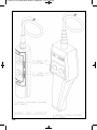
1
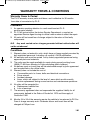
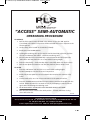
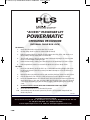
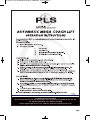
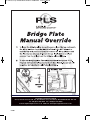
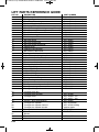
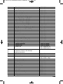
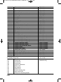
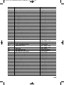
PLS Access Op & Main Manual 2014 12/06/2014 13:31 Page 1
Access Operation &
Maintenance Manual
(including Mega Lift)
Tel: +44 (0)121 552 0660
www.passengerliftservices.co.uk
PLS Access Op & Main Manual 2014 12/06/2014 13:31 Page 2
Issue 1.3
March 2010
This document is the exclusive property of ‘PASSENGER LIFT SERVICES’ and is
copyright in which all rights are reserved, no copy of this document can be made
without the written authority of the proprietors of the copyright.
Written and complied by: A. Beck B.Sc.
CAD work by: T. Urbanski M.Sc, G. Fisher, P. Edwards
Technical contributions from: D. Wheatcroft, P. Edwards & A. Tompkins
PLS Access Op & Main Manual 2014 12/06/2014 13:31 Page 3
Information
Section 1
PLS Access Op & Main Manual 2014 12/06/2014 13:31 Page 4
IMPORTANT
The new lift owner/operator should refer to this manual for
operating instructions, future warranty and servicing work.
This manual should be kept safely for the entire working life
of the lift.
When quoting the lift serial number to the manufacturers,
this number can be found in the top right hand corner of the
S.W.L. sticker located on the roll-off ramp. The number is
also stamped into the aluminium platform main section
(near side).
PLS Access Op & Main Manual 2014 12/06/2014 13:31 Page 5
Contents
Section
1
2
Page
Information
Warranty terms & conditions
Access Lift technical data
LOLER information
Safety instructions
Safety instructions for scooters and large –
Powered wheelchairs
Access Semi-Auto operating procedure
Access Powermatic operating procedure
Mega coach lift operating procedure
Hydraulic bridge plate manual override
Savery hand pump operating procedure
Monarch hand pump operating procedure
PLS Lift daily check sheet
Service record sheet
Monthly safety checks
6 monthly safety checks
Lift trouble shooting
Floor height adjustment
How to set the bridge plate mechanism
Lubrication diagram
Decal (sticker) diagram
Hand set layout
1.06
1.07
1.08
1.09
1.10
1.11
1.12
1.13
1.14
1.15
1.16
1.17 – 1.18
1.19
1.20
1.21
1.22 – 1.23
1.24
Ordering spare parts (drawings)
Spare parts order form
Lift assembly drawing
Flatback box drawing
Stepback box drawing
Standard carriage assembly
Mega carriage assembly
Standard box lock
In/out motor assembly
Standard arm assembly
Mega arm assembly
Standard platform assembly
Double bridge plate mechanism platform
Hydraulic bridge plate mechanism platform
Hydraulic elements for bridge plate mechanism
Standard handrail assembly
Bridge plate assembly
2.01
2.02
2.03
2.05
2.07
2.09
2.11
2.12
2.13
2.14
2.15
2.17
2.19
2.21
2.22
2.23
1.01
1.02
1.03 – 1.04
1.05
–
–
–
–
2.04
2.06
2.08
2.10
– 2.16
– 2.18
– 2.20
– 2.24
PLS Access Op & Main Manual 2014 12/06/2014 13:31 Page 6
Contents cont...
Mega handrail assembly
Standard roll-off ramp assembly
Oil control pump assembly
Savery pump assembly
2.25
2.26
2.27
2.28
3
Hydraulic section
Access lift hydraulic schematic
3.01
Lift with hydraulic bridge plate schematic
3.02
Roll-off ramp cylinder
3.03
Bridge plate cylinder
3.04
Lifting cylinder assembly
3.05
Standard lifting cylinder
3.06
Hybrid lifting cylinder
3.07
Short mega lifting cylinder
3.08
Mega lifting cylinder
3.09
Long mega lifting cylinder
3.10
Layout of hydraulic hoses
3.11
Layout of hydraulic hose for hydro bridge plate 3.12
Hose identification
3.13 – 3.14
4
Electrical section
Powermatic pump wiring diagram
Powermatic carriage loom diagram
Hydraulic bridge plate electrical diagram
Hydraulic bridge plate carriage loom
Hydraulic bridge plate platform loom
Hydraulic bridge plate control units
4.01
4.02
4.03
4.04
4.05
4.06
Lift installation & testing section
Fitting sequence
Load testing a fitted lift
Bracket fit to box section chassis
Bracket fit to open section chassis
Umbilical positioning
Solenoid and relay types
PLS recommended torque settings
LOLER certificate
Weight test certificate
Welding information
5.01 – 506
5.07
5.08 – 5.09
5.10 – 5.11
5.12
5.13
5.14
5.15
5.16
5.17
Part numbers section
Lift parts reference guide
6.01 – 6.04
5
6
PLS Access Op & Main Manual 2014 12/06/2014 13:31 Page 7
WARRANTY TERMS & CONDITIONS
Warranty Cover & Period
The P.L.S. warranty covers parts and labour, and is effective for 36 months
from date of commission by P.L.S.
Procedure
1
2
3
An operator requiring attention to a unit would contact P.L.S.
quoting serial number.
P.L.S. will instruct either the factory Service Department, or contact an
appointed Service Agent issuing an official order number to effect the repair.
All parts will be issued free of charge subject to the return of the faulty
components.
N.B. Any work carried out or charges generated without authorisation will
not be reimbursed.
Conditions
1
2
3
4
5
6
7
8
Warranty does not extend to units, which have not been regularly serviced by
duly appointed personnel. Including a 6 monthly LOLER certification.
All warranty work must be carried out by factory appointed personnel using
approved parts and materials.
The units must be made available for repair during normal working hours
(08.00-17.00 Hours Monday to Friday excluding public holidays).
No delivery costs or travel time will be reimbursed except by prior agreement
and as specified on the official order.
Warranty does not include the cost of:
a Consumable parts i.e. fuses, bulbs and electrical connections.
b Driver misuse.
c Accident damage.
d Items, which are subject to the level of, wear which would normally
involve replacement during normal service and maintenance operations.
No claim will be accepted for:
a Replacement vehicle hire.
b Loss of earnings.
The warranty agreement does not supersede the suppliers liability for all
components defined in the Sales of Goods Act 1979 and the supply of
Goods Act 1982.
Months 24 to 36 of the warranty require the vehicle to be returned to PLS for
Free of charge warranty work. Otherwise labour and travel time will be
charged at £40 per hour.
1.01
PLS Access Op & Main Manual 2014 12/06/2014 13:31 Page 8
Access Lift Technical Data
The lift is designed to transport:
One person in a wheelchair with or without an attendant, with a size not
larger than the width/length of platform space available, or weight over
the stated badge capacity (300Kgs unless upgraded by PLS).
Or
Two walking passengers. The operator should not attempt to transport
more than two people at a time because of increased risk of passenger
discomfort. The passengers also may require extra space for mobility
devices such as walking sticks and frames.
Capacity:
Standard Lift = 300Kgs (possible upgrade to 350Kgs available by
special request)
Specifications:
Lift type
Voltage
Power system
Hydraulic fluid type
Control
Bridge-plate width
Platform width
Platform length
Weight of lift (inc pump module)
Working pressure
Max amp draw at pump
Safety systems
1.02
:Underfloor cassette
:12Volts standard (24Volts available)
:Electro-hydraulic pump.
:PLS Blue (specific formulation) or ATF
:Pendant via wanderlead
:680mm or 730mm or 780mm (usable)
:725mm or 775mm or 825mm
:1240mm or 1410mm to 1780mm
:137Kgs to 234Kgs
:170 Bar MAX
:75 amps
:Dead man button control
:Platform roll-off barrier (ramp)
:Bridging plate
:Main power isolation switch
:& or Driver isolation switch
:Hose valves fitted inside cylinder body
:Hydraulic hoses rated x 4
:Stow position warning light (optional)
:Flashing LED side light pods x 2
(optional)
PLS Access Op & Main Manual 2014 12/06/2014 13:31 Page 9
Important Information
LOLER ‘98
What is LOLER?
The Lift Operations and Lifting Equipment Regulations 1998 which came into force on 5th
December 1998.
Basically LOLER replaced existing legal requirements relating to the use of Lifting
equipment.
What does LOLER do?
The Regulations require that lifting equipment provided for use at work is:
1 Strong and stable enough for the particular use and correctly marked to
indicate safe working loads.
2 Used safely in a planned and organised way by Competent People.
3 Examined, inspected and tested on a regular basis by Competent People.
How can PLS help?
Passenger Lift Services offer a Bi-Annual examination and weight testing programme
carried out only by PLS Approved engineers.
Each certificate is individually numbered and security marked to ensure authenticity.
To begin your programme of
compliance with LOLER ‘98 call now on:
0121 552 5503
What equipment does LOLER cover?
All equipment used at work for lifting or lowering loads.
Who do the regulations affect?
Any person responsible for providing or having control over the provision of lifting equipment
in the workplace - the duty holder.
What should the duty holder be aware of?
The Health and Safety Executive (HSE) have produced a publication - ‘The Safe Use of
Lifting Equipment’ lifting operations and lifting regulations 1998 approved code of practice
and guidance (APCPG).
How do I obtain a copy of this publication?
By mail order from:
HSE Books, PO Box 1999, Sudbury, Suffolk, CO10 6FS
Tel: 01787 881165 Fax: 01787 313995
What do the regulations require me to do?
The regulations impose a number of requirements on the duty holder including ensuring that:
•
The lift operations are carried out and supervised in a safe manner by
Competent People.
1.03
PLS Access Op & Main Manual 2014 12/06/2014 13:31 Page 10
What do the regulations require me to do?
The regulations impose a number of requirements on the duty holder including ensuring that:
•
The lift operations are carried out and supervised in a safe manner by
Competent People.
•
Where equipment is used for lifting people it is suitably marked and safe for the
purpose.
•
Before the lifting equipment is used for the first time it is thoroughly examined
by a Competent Person and thereafter at regular intervals.
Who Qualifies as a Competent Person?
A person who has appropriate practical and theoretical knowledge and experience for the
lifting equipment to be examined to enable them too detect actual or potential defects or
weaknesses and to asses their importance in relation to the equipment and it’s installation.
i.e. A person holding a service training certificate by the manufacturer.
It is essential that the competent person is sufficiently independent and impartial to
allow objective decisions to be made.
Does this mean the competent person must be employed by an
outside company?
No BUT if in-house examiners are used you must ensure that their total impartiality to carry
out the examination(s) without ‘fear or favour’.
Are the regular intervals specified?
YES - but you have a choice - you can follow the specified period intervals of at least six
months for equipment used for lifting people or
You can have a examination scheme drawn up and have the equipment examined in accordance with this scheme.
Are there other criteria requiring a thorough examination?
1
2
3
4
5
6
After installation and before putting into service (Installation and Weight Test
Certificate)
If re installed on a different vehicle.
Following exceptional circumstances which may jeopardise the safety of the lift.
Following an accident or dangerous occurrance.
After significant changes in conditions of use.
After long periods out of use.
How do the regulations relate to other HSE legislation?
The requirements of the regulations need to be considered alongside other Health and
Safety Law in particular the Management of Health and Safety at Work regulations which
contain important duties regarding the preparation of a risk assessment.
How are the regulations enforced?
Health and Safety Officers enforce the regulations.
The Duty Holder must be able to produce a valid examination certificate
when requested by a Health and Safety Officer.
1.04
PLS Access Op & Main Manual 2014 12/06/2014 13:31 Page 11
Passenger Lift Services Limited
Unit 2, Summit Crescent Ind. Est., Off Roebuck Lane, Smethwick, West Midlands B66 1BT. U.K.
Tel: +44 (0)121 552 0660 Fax: +44 (0)121 552 0200
E-mail: [email protected] Web Site: www.passengerliftservices.co.uk
1.05
PLS Access Op & Main Manual 2014 12/06/2014 13:31 Page 12
Safety Instructions for ‘Scooters’ and Large
Powered Wheelchairs
Before operating tail lift:
Fully familiarize yourself with lift controls, relevant safety procedures and possible hazards, signified by
warning labels or highlighted in your ‘Operators Risk Assessment’.
Tail lift safety:
●
●
●
●
●
●
●
●
Only an authorised (fully trained) operator must control the lift.
Secure vehicle doors fully open, well clear of the lift platform.
Keep within the stated maximum safe working load (SWL).
Keep people away from the operating area (inside and outside of vehicle).
Ensure that the platform is always level (horizontal, not more than 5º).
NEVER leave the lift unattended at ground level if passengers are on board.
When lift is not in use the controls should be deactivated.
Ensure that the lift is correctly stowed after loading.
Operators ensure that:
●
●
●
●
●
●
●
●
●
Lift will lower to firm, level ground.
Scooter or powered wheelchair is not larger than lift platform in any direction.
Tail lift is in a FULLY operational condition. Report any defects.
Lift bridging-plate lands flat onto vehicle floor.
Roll-off ramp is set vertically (approx. 80º), and fully operational.
Accompany the passenger on the lift if possible, but do not overload the lift.
You have a clear view of the lift platform before the scooter moves onto it.
NEVER leave passengers unattended at any time.
The passenger should not be required to operate ANY controls.
Loading & Unloading procedure:
●
●
●
●
●
●
●
●
●
●
●
●
Explain to passenger the sequence of movements that will occur.
Where possible passenger should dismount scooter and board vehicle separately.
Ensure that the lift platform and area around the lift are free from obstruction.
Ensure that the lift platform is in the correct position before moving onto it.
Scooter should be pushed onto the lift platform, NOT DRIVEN.
Ensure that persons or equipment do not overhang the platform.
Scooter breaks are applied BEFORE lift begins motion (or wheels blocked).
All power to scooter is turned OFF.
Operate lift platform to vehicle floor.
Scooter is pushed off the lift platform, NOT DRIVEN.
The scooter should be clamped to the vehicle floor using the correct equipment.
The passenger utilises the static vehicle seats and seatbelts.
Please note: The transportation of scooters and large powered wheelchairs may require a ‘NON STANDARD’
tail lift size or specification. Where possible PLS can provide longer, wider platforms, higher roll-off ramps
Passenger Lift Services Limited
Unit 2, Summit Crescent Ind. Est., Off Roebuck Lane, Smethwick, West Midlands B66 1BT. U.K.
Tel: +44 (0)121 552 0660 Fax: +44 (0)121 552 0200
E-mail: [email protected] Web Site: www.passengerliftservices.co.uk
1.06
PLS Access Op & Main Manual 2014 12/06/2014 13:31 Page 13
“ACCESS” SEMI-AUTOMATIC
OPERATING PROCEDURE
TO OPERATE;
1.
Pull the lift isolation switch (if fitted in the drivers area) to the ‘ON’ position.
If not fitted in the drivers area power will be activated when doors adjacent to the
lift are opened.
2.
Unclip safety chain located on r/hand side (if fitted).
3.
Briefly press the ‘DOWN’ button.
4.
Holding the retaining catch up (located on the left hand side of the lift), pull the
lift out from beneath the vehicle - release the retaining catch.
5.
Ensuring that the lift has travelled fully out from beneath the vehicle press the
‘UP’ button until the platform is at a comfortable working height.
6.
Raise the hand rail(s) - check that they have located fully down into their sockets.
7.
Pull the rear platform extension out until the platform surface ‘drops’ flush.
TO STOW;
1.
Press the ‘UP’ button until the lift is at a comfortable working height.
Do NOT attempt to stow the lift from a low position.
2.
Briefly lift the rear platform surface and push the rear platform extension fully
home.
3.
Lift the hand rail(s) out of its socket and fold across the platform surface.
4.
Press the ‘DOWN’ button until the lift stops and then push the lift underneath the
vehicle. CHECK that the lift is stowed correctly by attempting to pull the lift out
again without releasing the retaining catch.
5.
RE-ATTACH SAFETY CHAIN ONTO HOLE PROVIDED IN ROLL-OFF RAMP.
6.
Push the lift isolation switch to the ‘OFF’ position - if fitted. Otherwise closing
doors will isolate lift.
PLS 211A
Passenger Lift Services Limited
Unit 2, Summit Crescent Ind. Est., Off Roebuck Lane, Smethwick, West Midlands B66 1BT. U.K.
Tel: +44 (0)121 552 0660 Fax: +44 (0)121 552 0200
E-mail: [email protected] Web Site: www.passengerliftservices.co.uk
1.07
PLS Access Op & Main Manual 2014 12/06/2014 13:31 Page 14
“ACCESS” PASSENGER LIFT
POWERMATIC
OPERATING PROCEDURE
(EXTERNAL CABLE BOX LOCK)
TO OPERATE;
1.
Open the vehicle door(s) where the lift is located.
2.
Unclip safety chain located on r/hand side (if fitted).
3.
Pull the external box lock handle (located above the lift), press “UP” button on
the handset, release external box lock handle.
4.
The lift will travel to the out position then automatically begin to rise. Stop the
lift at a comfortable working height.
5.
Raise the hand rails, making sure that they have located fully into their sockets.
6.
Pull the platform extension out until the platform surface ‘drops’ flush.
TO STOW;
1.
Press the ‘UP’ button until the lift is at a comfortable working height (This must
be above the level of the lift cassette). DO NOT attempt to stow the lift from a
low position.
2.
Briefly lift the rear platform surface and push the platform extension fully home.
3.
Lift the hand rails out of their sockets and fold across the platform surface.
4.
Press the ‘DOWN’ button. The lift will reach the stow position then automatically
divert the power to the “IN” function. With the lift away check that it is stowed
correctly by attempting to pull the lift out again, without pulling the retaining
catch.
5.
RE-ATTACH SAFETY CHAIN ONTO HOLE PROVIDED IN ROLL-OFF RAMP.
6.
Close the vehicle doors to isolate the lift power.
N.B.
Should the power IN & OUT system fail, the lift can be pulled and pushed into
the box by hand.
PLS 213A
Passenger Lift Services Limited
Unit 2, Summit Crescent Ind. Est., Off Roebuck Lane, Smethwick, West Midlands B66 1BT. U.K.
Tel: +44 (0)121 552 0660 Fax: +44 (0)121 552 0200
E-mail: [email protected] Web Site: www.passengerliftservices.co.uk
1.08
PLS Access Op & Main Manual 2014 12/06/2014 13:31 Page 15
Passenger Lift Services Limited
Unit 2, Summit Crescent Ind. Est., Off Roebuck Lane, Smethwick, West Midlands B66 1BT. U.K.
Tel: +44 (0)121 552 0660 Fax: +44 (0)121 552 0200
E-mail: [email protected] Web Site: www.passengerliftservices.co.uk
1.09
PLS Access Op & Main Manual 2014 12/06/2014 13:31 Page 16
Passenger Lift Services Limited
Unit 2, Summit Crescent Ind. Est., Off Roebuck Lane, Smethwick, West Midlands B66 1BT. U.K.
Tel: +44 (0)121 552 0660 Fax: +44 (0)121 552 0200
E-mail: [email protected] Web Site: www.passengerliftservices.co.uk
1.10
PLS Access Op & Main Manual 2014 12/06/2014 13:31 Page 17
“ACCESS” PASSENGER LIFT
AUXILIARY HAND PUMP
OPERATION PROCEDURE
(SAVERY POWERPACK)
A hand pump allows the lift to be used in the event of any electrical fault. The unit which is integral with the
powerpack comprises a single acting piston pump with removable operating lever. This is found either under the
rear of the vehicle on the nearside or internally on the nearside rear. Remove the black plastic cover to gain access
to the pump. To use the pump proceed as follows:
PREPARATION
1. Take the operating lever from its stowage.
LOWERING VALVE
MANUAL OVERRIDE
MANUAL HAND PUMP HANDLE
TO LOWER THE PLATFORM
2. Push in and turn anti-clockwise the RED lowering valve.
TO RAISE THE PLATFORM
3. Close the RED lowering valve by turning clockwise.
4. Connect the operating lever to the hand pump.
5. Operate the lever until platform is at required height.
STOWAGE PROCEDURE
6. Using the hand pump, stow the platform in the normal way.
When power is restored to the lift, check that the ‘RED lowering valve’ is correctly closed (clockwise).
7. Stow the operating lever.
N.B. Should the power IN & OUT system fail, the lift can be pulled and pushed into the box by hand.
PLS 215
Passenger Lift Services Limited
Unit 2, Summit Crescent Ind. Est., Off Roebuck Lane, Smethwick, West Midlands B66 1BT. U.K.
Tel: +44 (0)121 552 0660 Fax: +44 (0)121 552 0200
E-mail: [email protected] Web Site: www.passengerliftservices.co.uk
1.11
PLS Access Op & Main Manual 2014 12/06/2014 13:31 Page 18
“ACCESS” PASSENGER LIFT
AUXILIARY HAND PUMP
OPERATION PROCEDURE
(MONARCH POWERPACK)
A hand pump allows the lift to be used in the event of any electrical fault. The unit which is integral with the
power pack comprises a single acting piston pump with removable operating lever. This is found either under
the rear of the vehicle on the nearside or internally on the nearside. Remove the black plastic cover to gain
access to the pump. To use the pump proceed as follows:
PREPARATION
1. Take the operating lever from its stowage.
Note: The notched end is also used as a ‘spanner’ for operating the relief valve.
TO LOWER THE PLATFORM
2. Open the relief valve (anti-clockwise).
TO RAISE THE PLATFORM
3. Close the relief valve (clockwise).
4. Connect operating lever to hand pump.
5. Operate lever until platform is at required height.
STOWAGE PROCEDURE
6. Using the hand pump, stow the platform in the normal way.
When power is restored to the lift, check that the relief valve is firmly closed (clockwise).
7. Stow the operating lever.
N.B. Should the power IN & OUT system fail, the lift can be pulled and pushed into the box by hand.
PLS 215A
Passenger Lift Services Limited
Unit 2, Summit Crescent Ind. Est., Off Roebuck Lane, Smethwick, West Midlands B66 1BT. U.K.
Tel: +44 (0)121 552 0660 Fax: +44 (0)121 552 0200
E-mail: [email protected] Web Site: www.passengerliftservices.co.uk
1.12
PLS Access Op & Main Manual 2014 12/06/2014 13:31 Page 19
Daily Check Sheet
1.13
PLS Access Op & Main Manual 2014 12/06/2014 13:31 Page 20
Access Service Data Sheet
Date lift was first issued: ............./.............../..............
Lift requires monthly checks and lubrication by driver/operator. Refer to Maintenance
manual for instructions. Every six months service and twelve monthly weight test should
be carried out by an appointed service engineer.
Month 1
Month 2
Month 3
Date: .........../............/........... Date: .........../............/........... Date: .........../............/...........
Driver/Operator
Driver/Operator
Driver/Operator
Name
Name
Name
Signature
Signature
Signature
Month 4
Month 5
Month 6
Date: .........../............/........... Date: .........../............/........... Date: .........../............/...........
Driver/Operator
Driver/Operator
Driver/Operator
Name
Name
Name
Signature
Signature
Signature
Month 7
Month 8
Month 9
Date: .........../............/........... Date: .........../............/........... Date: .........../............/...........
Driver/Operator
Driver/Operator
Driver/Operator
Name
Name
Name
Signature
Signature
Signature
Month 10
Month 11
Month 12
Date: .........../............/........... Date: .........../............/........... Date: .........../............/...........
Driver/Operator
Driver/Operator
Driver/Operator
Name
Name
Name
Signature
Signature
Signature
This page must be produced when claiming warranty repairs.
1.14
PLS Access Op & Main Manual 2014 12/06/2014 13:31 Page 21
Monthly Safety Checks for Operators
Regular lift maintenance is recommended at MONTHLY intervals by the lift
operating company. The working life of your lift will be greatly prolonged if these
steps are adhered to.
This should include the following:
1.
Check for obvious signs of damage, replace parts as necessary.
2.
Check the operation and stowing of the lift, if the platform base is touching the
bottom of the box adjust stow height (parts shown on page 2.13, # 26) by
raising the N/S and O/S stowing bolts on the rocker.
3.
Check the box lock operation (page 2.11) by attempting to pull the lift out of
the box with the lock engaged. If this can be achieved, the hook (7) will need
to be LOWERED in relation to the handle (12) and the lock nut (180) firmly
re-tightened.
4.
Check the carriage lock (parts shown on page 2.07, # 46) operation by
attempting to push the lift back into the box once the platform has been fully
deployed. If this can be achieved the carriage lock mechanism will require
adjustment.
5.
Check the rear roll-off-ramp operation. Check ramp ‘dummy pin’ (part shown
on page 2.15 # 72)which holds ramp in vertical position whilst lift is stowed.
Lubricate roll-off pivots with silicone spray.
6.
Check bridging plate operation (parts shown on pages 2.15 – 2.18) see page
1.20 for full adjustment instructions.
7.
Check platform extension operation and security of alloy sheet. N.B. DO NOT
overtighten M6 bolts which hold extension alloy! Check platform end stops
(part shown on page 2.15, # 177) are tight and vertically aligned.
8.
Check hand rail operation and security. If components are corroded they
should be replaced due to potential hazard to users! Check location pivot pins,
via the M8 S/S grub screws, these should be thread locked into position.
9.
When cleaning the vehicle wash the working platform of the lift.
10. Check ‘pull out’ handle is fully secure.
11. Check Up/Down pump for fluid leaks and loose/corroded electrics. Top up
reservoir (with lift at ground position) with PLS Blue hydraulic oil, do NOT
overfill. Coat any exposed electrics with dielectric grease (or similar) to
protect.
12. Lubricate lift in accordance with ‘Lubrication Diagram’ page 1.21.
IF IN DOUBT CONTACT THE MANUFACTURER.
1.15
PLS Access Op & Main Manual 2014 12/06/2014 13:31 Page 22
Maintenance 6 monthly,
for appointed Service Engineers
As monthly safety checks plus:
1.
Check arm pivot pins, bearings and retaining grub screws (page 2.13 – 2.14).
2.
Check cylinder pivot pins and grub screws (page 2.13 – 2.14).
3.
Check cylinders for oil leaks, ensure ‘end gland’ (page 3.05 # 4) is tight.
Replace piston ‘o’ ring (seal) if leaking.
4.
Remove bottom sheet, check all hoses and fittings for leaks, wear or
perishing. When bottom sheet is replaced remember to position retaining bolts
with the nuts on the OUTSIDE of stowage box.
5.
Remove lift from box to check centre bearings and carriage mechanisms. Lift
is removed by unbolting ‘carriage stops’ (page 2.03 #2) and detaching
‘umbilical’ via the quick release coupling (QRC) (page 3.11) and electrical
connector on the rear of the carriage.
N.B. When electrical connector is re-positioned the cable tie MUST be
replaced (see drawings on page 5.12 for correct alignment).
6.
Clean the interior of the stowage cassette and degrease the side tracks and
centre rack (or guide) with solvent. DO NOT GREASE TRACKS OR CENTRE
GUIDE, USE SILICONE SPRAY ONLY.
7.
Check nylon strips on platform surface for wear, replace if necessary.
8.
Check bridging plate operation is correct. The bridging plate must land flush
with the vehicle floor and NOT form a trip hazard. For full adjustment of the
mechanism see page 1.20.
9.
Check that the lift mounting brackets and track bolts are tight / secure
(page 5.08) and free from damage. Corrosion in this area of the lift is likely to
occur, however if in an advanced state components should be exchanged for
new items.
10. Check manual hand pump operation (see page 1.11 - 1.12), lubricate all pivot
points. REMEMBER TO RETURN MANUAL TAP TO THE CLOSED
POSITION.
11. Check condition and security of arm side guards (page 2.13 #61), replace if
damaged.
IF IN DOUBT CONTACT THE MANUFACTURER.
1.16
PLS Access Op & Main Manual 2014 12/06/2014 13:31 Page 23
Access Trouble Shooting
1.17
PLS Access Op & Main Manual 2014 12/06/2014 13:31 Page 24
1.18
PLS Access Op & Main Manual 2014 12/06/2014 13:31 Page 25
Floor height adjustment of platform
(also vertical stowing position on rear of vehicle)
Should it be necessary to adjust the lift to vehicle floor height, or if an imbalance of
cylinder stroke requires adjustment, the following steps should be taken:
1
Remove the plastic top and bottom arm cover, retained with cap headed bolts.
2
Undo the 24mm lock nut at cylinder ends.
3
With the lift powered down to the floor (i.e. pressure off the hydraulic system)
turn the pistons anti-clockwise to increase the lift height or clockwise to
decrease the lift height.
4
Power the lift up to floor height and put the platform in it’s vertical position.
Final adjustment to correct a cylinder imbalance is carried out in the same
manner.
5
Re-tighten lock nuts and refit plastic arm guards.
N.B. Under no circumstances should the thread be unscrewed more than 30mm as
insufficient thread portion will be left in the cylinder end resulting in possible damage to cylinder, lift and personnel. Should it be necessary to extend beyond this
point please refer to our technical department.
1.19
PLS Access Op & Main Manual 2014 12/06/2014 13:31 Page 26
How to set (or re-set) the mechanical
bridging plate system
1
2
Power lift to MAXIMUM UP position.
Fold bridge-plate (I) over (to vehicle) to its maximum position. With the
bridge-plate in this position the plunger bar (B) should be 2 to 3mm away
from the roller (or cam)(H) on the bridge-plate hinge (I).
Lock plunger bar (B) into position with mole grips.
Set TOGGLE (F) length, there must be a minimum of 20mm of thread
showing.
Push ARM CRANK (K) (from the left to right) into the platform. There should
be one thick washer (N) between the inside of the platform and the CAM (J).
Push CAM fully across to the left, and rotate forward until it touches the
bridge-plate rocker bar (G). Tighten one (of the four) grub screws (L) to
retain position.
Drill through the M6 holes in the CAM and just into the CRANK (K) (approx.
2mm), with a 5mm drill bit. Do this to the three exposed M6 tapped holes in
the CAM (J).
Utilizing BLUE thread-lock fit M6 x 6mm, ‘dog-nosed’ grub screws into the
available threads.
Remove the original ‘retaining’ grub screw, thread-lock and re-tighten.
Lower the lift platform, then power up to floor position to ‘settle’ the
mechanism.
Set the single collar (D) forwards to take up any ‘over-stroke’ in the plunger.
3
4
5
6
7
8
9
10
Fig 1
Fig 2
.
Key:
A = Double plunger
B = Plunger bar
C = Twin collar
D = Single collar
E = Plunger bar spring
F = Toggle
G = Rocker bar
1.20
H = Bridge-plate hinge roller (or cam)
I = Bridge-plate hinge
J = Cam
K = Arm crank
L = M6 x 6mm grub screw, dog-nosed
M = Rocker bar retaining pin, and split pin
N = Cam spacer (thick washer)
PLS Access Op & Main Manual 2014 12/06/2014 13:31 Page 27
1.21
PLS Access Op & Main Manual 2014 12/06/2014 13:31 Page 28
1.22
PLS Access Op & Main Manual 2014 12/06/2014 13:31 Page 29
1.23
PLS Access Op & Main Manual 2014 12/06/2014 13:31 Page 30
1.24
PLS Access Op & Main Manual 2014 12/06/2014 13:31 Page 31
Ordering spare parts
Section 2
PLS Access Op & Main Manual 2014 12/06/2014 13:31 Page 32
Ordering spare parts for Access Lift
ATTN: PLS Service/Parts Department
Customer:
Lift No:
Contact:
Order No:
Address:
Tel No:
Date:
Discount %:
Postcode:
Quantity
Carriage £:
Description
Part No.
Price each
Sub Total:
Sub Total (after discount)
Carriage:
VAT:
Total:
2.01
Total
PLS Access Op & Main Manual 2014 12/06/2014 13:31 Page 33
2.02
PLS Access Op & Main Manual 2014 12/06/2014 13:31 Page 34
2.03
PLS Access Op & Main Manual 2014 12/06/2014 13:31 Page 35
2.04
PLS Access Op & Main Manual 2014 12/06/2014 13:31 Page 36
2.05
PLS Access Op & Main Manual 2014 12/06/2014 13:31 Page 37
2.06
PLS Access Op & Main Manual 2014 12/06/2014 13:31 Page 38
2.07
PLS Access Op & Main Manual 2014 12/06/2014 13:31 Page 39
2.08
PLS Access Op & Main Manual 2014 12/06/2014 13:31 Page 40
2.09
PLS Access Op & Main Manual 2014 12/06/2014 13:31 Page 41
2.10
PLS Access Op & Main Manual 2014 12/06/2014 13:31 Page 42
2.11
PLS Access Op & Main Manual 2014 12/06/2014 13:31 Page 43
2.12
PLS Access Op & Main Manual 2014 12/06/2014 13:31 Page 44
2.13
PLS Access Op & Main Manual 2014 12/06/2014 13:31 Page 45
2.14
PLS Access Op & Main Manual 2014 12/06/2014 13:31 Page 46
2.15
PLS Access Op & Main Manual 2014 12/06/2014 13:31 Page 47
2.16
PLS Access Op & Main Manual 2014 12/06/2014 13:31 Page 48
2.17
PLS Access Op & Main Manual 2014 12/06/2014 13:31 Page 49
2.18
PLS Access Op & Main Manual 2014 12/06/2014 13:31 Page 50
2.19
PLS Access Op & Main Manual 2014 12/06/2014 13:31 Page 51
2.20
PLS Access Op & Main Manual 2014 12/06/2014 13:31 Page 52
2.21
PLS Access Op & Main Manual 2014 12/06/2014 13:31 Page 53
2.22
PLS Access Op & Main Manual 2014 12/06/2014 13:31 Page 54
2.23
PLS Access Op & Main Manual 2014 12/06/2014 13:31 Page 55
2.24
PLS Access Op & Main Manual 2014 12/06/2014 13:31 Page 56
2.25
PLS Access Op & Main Manual 2014 12/06/2014 13:31 Page 57
2.26
PLS Access Op & Main Manual 2014 12/06/2014 13:31 Page 58
2.27
PLS Access Op & Main Manual 2014 12/06/2014 13:31 Page 59
2.28
PLS Access Op & Main Manual 2014 12/06/2014 13:31 Page 60
Hydraulic
Section 3
PLS Access Op & Main Manual 2014 12/06/2014 13:31 Page 61
3.01
PLS Access Op & Main Manual 2014 12/06/2014 13:31 Page 62
3.02
PLS Access Op & Main Manual 2014 12/06/2014 13:31 Page 63
3.03
PLS Access Op & Main Manual 2014 12/06/2014 13:31 Page 64
3.04
PLS Access Op & Main Manual 2014 12/06/2014 13:31 Page 65
3.05
PLS Access Op & Main Manual 2014 12/06/2014 13:31 Page 66
3.06
PLS Access Op & Main Manual 2014 12/06/2014 13:31 Page 67
3.07
PLS Access Op & Main Manual 2014 12/06/2014 13:31 Page 68
3.08
PLS Access Op & Main Manual 2014 12/06/2014 13:31 Page 69
3.09
PLS Access Op & Main Manual 2014 12/06/2014 13:31 Page 70
3.10
PLS Access Op & Main Manual 2014 12/06/2014 13:31 Page 71
3.11
PLS Access Op & Main Manual 2014 12/06/2014 13:31 Page 72
3.12
PLS Access Op & Main Manual 2014 12/06/2014 13:31 Page 73
3.13
PLS Access Op & Main Manual 2014 12/06/2014 13:31 Page 74
3.14
PLS Access Op & Main Manual 2014 12/06/2014 13:31 Page 75
Electrical
Section 4
PLS Access Op & Main Manual 2014 12/06/2014 13:31 Page 76
4.01
PLS Access Op & Main Manual 2014 12/06/2014 13:31 Page 77
4.02
PLS Access Op & Main Manual 2014 12/06/2014 13:31 Page 78
4.03
PLS Access Op & Main Manual 2014 12/06/2014 13:31 Page 79
4.04
PLS Access Op & Main Manual 2014 12/06/2014 13:31 Page 80
4.05
PLS Access Op & Main Manual 2014 12/06/2014 13:31 Page 81
4.06
PLS Access Op & Main Manual 2014 12/06/2014 13:31 Page 82
Lift installation &
testing
Section 5
PLS Access Op & Main Manual 2014 12/06/2014 13:31 Page 83
1. GENERAL INSTRUCTIONS
FOR LIFT INSTALLATION
1.1 Panel Vans
The tail lift is supported with four brackets which are bolted through the vehicle chassis. On
nearly all PANEL VANS the rear brackets pick up on existing holes in the chassis although
the near-side rear bracket may require relocating towards the front of the vehicle to allow for
the box lock mechanism (see page 5.08 – 5.11). This will require drilling new holes in the
chassis or bracket to suit. Some front bracket holes may require enlarging depending on
bolts used!
•
•
•
Note: when drilling through box section always use spacer tubes to prevent
deformation of the vehicle sections.
Never drill two holes less than 10mm apart.
Do not drill too closely to the edge of a chassis member.
The brackets are positioned roughly in each of the four corners of the lift box. They will normally coincide with spaces between ‘TRACK BOLTS’ or OVER the specially turned down
studs.
1.2 Coach Built Vehicles (in addition to 1.1)
On most coach built vehicles it will be necessary to drill new holes in the chassis for the
installation brackets (occasionally holes exist in the chassis ends which can be used). The
rear brackets MUST be mounted a minimum of 250mm from the ‘mouth’ of the lift box. This
will allow clearance for the box lock mechanism. The position of fitting brackets may also be
determined via the body mounting points. Always use the strongest parts of the chassis
available.
1.3
The lift is usually mounted as close to the underside of the vehicle chassis as possible for
maximum ground clearance. Normally however the rear valance of the vehicle protrudes
downward, lower than any of the chassis members, e.g. position ‘A’ on page 5.08 – 5.09.
Position ‘A’ can determine length of ‘B’, this is the drop from the underside of the chassis to
the bottom lip of the tail lift box. However on some coach built vehicles length ‘B’ is
determined by the type of lift fitted.
•
•
Remember to check lift build paperwork for a top of box to vehicle floor height
measurement. A top of box to underside of chassis dimension may also be included.
Remember to add box depth to measurements to extrapolate potential ground
clearance.
In some cases it may be necessary to cut the rear valance, to gain extra ground clearance.
1.4
It should be clarified that the front of the tail lift is the end of the box closest towards the front
of the vehicle, on page 5.08 – 511, position ‘Y’. The back of the tail lift is the open end of the
box, which is at the rear of the vehicle, position ‘X’.
5.01
PLS Access Op & Main Manual 2014 12/06/2014 13:31 Page 84
1.5
The length of ‘B’ on page 5.08 – 5.11, can be the same for the front and rear brackets
although usually the front brackets are lower, thus allowing a tilt on the box (positive tilt). This
means that point ’Y’ can be a maximum of 25mm lower than point ‘X’ for ALL lifts. Note, for
POWERMATIC applications this distance should not be greater than 15mm. Note; check
that:
•
When platform lowers fully to ground it is level.
•
Front and rear of platform land at the same time.
•
Roll-off ramp reaches the ground easily.
Note: The front bracket should be as close to point ‘Y’ as possible.
1.6
When all four brackets have been attached to the chassis, tighten the bracket bolts on ONE
SIDE OF THE CHASSIS ONLY, leave the other side loose! Push the lift box under the
vehicle and lift the fixed bracket side into position and clamp. It may be necessary to remove
and relocate the track bolts (protruding from side of lift box). If bolts clash with bracket
positions replace with turned down head versions. Tighten all chassis bolts to brackets (see
page 5.14 for torque settings) and replace track bolts removed. The hydraulic support
bracket (top view page 5.12) should be retained wherever possible. This will locate the
external hose(s) correctly. Note:
•
•
HANDLE THE LIFT CASSETTE WITH GREAT CARE, GALVANIZED SECTIONS ARE
VERY SHARP.
Any track bolts removed should be replaced and tightened into position when the box
is correctly positioned. Turned down studs which are NOT covered by a bracket should
be replaced with M10 x 25mm bolts, retained with a spring washer.
1.7
The zinc plated top sheet should be secured into position at this stage (some vehicles will
require the sheet fitting into position prior to installing the box), as it facilitates handling the
cassette much easier. The top sheet is secured into position using a run of Polyethylene
Sealant around the top edges of the lift cassette. If the top sheet is required to be removable
it may be located with SHORT M6 bolts or ‘Duct tape’ (if Duct tape is used it will require
regular checks and possible replacement).
1.8
The final positioning of the box is also determined by the location of the extension arms,
when the lift is raised to its fully UP position (mainly Coach Built vehicles). See page 5.10 511. Ensure a floor end gap ‘G’ of at least 15mm, before the end of the platform extension
arms comes into contact with the rear of the vehicle, it may be necessary to pull the box out
from underneath the vehicle. It is usual for the RAISED HEIGHT to be less than the DROP
DISTANCE. Note;
•
5.02
Check lift doesn’t hit vehicle edge with platform extension closed prior to drilling and
fixing final cassette position.
PLS Access Op & Main Manual 2014 12/06/2014 13:31 Page 85
1.9
The cassette box is secured into position via M10 x 30mm Hex head (8.8 strength min) bolts,
washers and nylocks. Note;
•
THE BOLT HEADS MUST BE ON THE INSIDE OF THE LIFT CASSETTE WITH THE
WASHERS AND NYLOCKS ON THE OUTSIDE. If fitted backwards the length of bolt
will contact with lift innards and stop lift from functioning. The kit is supplied with 2 M10
x 30mm ‘turned down head’ bolts, these are used on the front bracket at the near side
of the vehicle. They fit behind the umbilical cable and allow it to fit closely to the side
of the box.
How to remove the lift innards
If the box is to be fitted first (lift innards added when box positioned) the lifting section will
need to be removed from the lift cassette box!
1)
2)
3)
4)
5)
6)
Remove the ‘stop blocks’ one fitted each side of the lift by removing the M8 bolts
(two bolts each).
When removed mark up the stop blocks Left and Right. These must be repositioned in
the same manner. If not the lift may power out too far!
Detach hydraulic QRC (quick release coupling) from rear for Carriage section.
Detach the electrical multiplug from rear of Carriage.
Remove cable ties holding umbilical to rear of Carriage.
The lift may now be removed from cassette.
AFTER REMOVAL PLACE A CABLE TIE AROUND THE ROLLER ARM OF THE ‘OUT & UP’
MICRO SWITCH, LOCATED ON THE RIGHT SIDE TOP OF THE CARRIAGE. THIS WILL
AVOID DAMAGING THE SWITCH WHEN REPLACING THE LIFT INTO CASSETTE.
Note: If the lift powers UP inside the cassette when re-installed, remember to cut off the
cable tie that has been fitted across the micro switch. Replace the cable tie that holds the
umbilical to the rear of the carriage (lower drawing page 5.12). Make sure that when the lift
is powered fully OUT the umbilical is not too tight!
2. INSTALLATION of HYDRAULIC’S & ELECTRIC’S
(See Hydraulic & Electrical sections in manual)
2.1
The lift ‘fitting kit’ is supplied with a length of 16mm battery cable and a separate length of
three core cable (0.75mm min). These should firstly be run from the lift position to the
battery and the position of the isolator switch respectively. Follow existing vehicle cables if
possible.
DO NOT ATTACH CABLES TO FUEL LINES OR BRAKE PIPES. DO NOT RUN THROUGH
HOLES IN CHASSIS OR MEMBERS WITH FUEL LINES. AVOID SHARP EDGES BY
PROTECTING CABLE WITH CONDUIT OR KNOCK-ON EDGING STRIPS.
The battery cable is protected via a circuit breaker which should be attached to the positive
feed on the battery. The isolator switch is either a door mounted earthing pin switch (mainly
panel vans), or a cab switch for coach built vehicles. These cables are then secured above
5.03
PLS Access Op & Main Manual 2014 12/06/2014 13:31 Page 86
the pump location on the near side, to the front of the rear brackets, if mounted externally.
The type of isolator switch is dependent on the vehicle specification. Door mounted
switches should be protected from damage and water ingress.
2.2
If the pump is to be mounted internally, the cables should be secured to the near side
corner at the back (rear) of the vehicle, and run through the floor with the hydraulic hose (and
umbilical wiring if Lift is a Powermatic type). PLS usually drill through the vehicle floor with
a 44mm diameter hole saw and protect the wiring and hoses with split 43mm conduit. The
lifts are usually supplied for external pump fitting, to give space inside the vehicles. However,
internal mounting will extend the working life of the powerpack greatly.
2.3
The three core cable is normally run up the near side pillar of the vehicle (panel vans) and
across to the door using fittings supplied. If a door switch is used this is drilled through the
door on the hinge side and adjusted to strike the pillar. The handset wire is run through a
grommet on the lock side of the door and all connections are made behind the door cover
panel.
If a cab switch is required (mainly coach built vehicles) run a 3 core cable to the front of the
vehicle (see wiring diagrams). On most coach built vehicles the handset (pendant control) is
fixed to the back panel of the vehicle adjacent to the near side door and connections made
using the small black plastic box supplied.
2.4
The hydraulic connection is made between the back of the pump plate and the connection
on the side of the cassette, using the flexible hose supplied in kit. This hose length can vary
depending on pump position required. The pump is attached to the mounting bracket using
2 off M10 x 60mm bolts. Note:
•
ONLY USE PLS SUPPLIED HYDRAULIC HOSES.
2.5
The 16mm earth strap for the pump is attached to a suitable ‘clean’ point on the vehicle
chassis, usually a bracket bolt. All other wiring should be routed to the pump using the large
plastic glands. All connections are made in accordance with the instructions on the wiring
blocks (number to number) fitted to the pump. The battery feed (live feed in) is attached to
the UP solenoid (mounted on the side of the pumps motor) of the loose terminal then
tightened. Note:
•
CONNECT THE LIFT WIRING ON THE CARRIAGE FIRST BEFORE CONNECTING
THE BATTERY POSITIVE.
2.6
When mounting the pump location bracket wherever possible the pump should be positioned
above the lift box (usually second set of holes from bottom of bracket).
NOTE: THE PUMP MUST BE POSITIONED SO THAT THE HANDPUMP CAN BE OPERATED SAFELY THROUGHOUT THE ENTIRE TRAVEL OF THE LIFT OPERATION.
5.04
PLS Access Op & Main Manual 2014 12/06/2014 13:31 Page 87
3. FITTING OF THE LIFT PLATFORM
INTO THE CASSETTE
3.1
When the lift box has been fitted, and both the electric’s and hydraulics installed, the lift
innards can be located into the box. With tilting the back edge of the lift a little the
cam-followers on the side of the lifts carriage, will locate on the box tracks. The lift can then
be pulled up to the horizontal position and pushed forward into the box until it is completely
home.
3.2
There will be two zinc plated solid metal blocks, usually located with a cable tie to the
handrails. These are the lift STOP BLOCKS, they should be bolted into the lift box just
underneath the side tracks, at position ‘W’ on page 5.08 – 5.11. The bolts used should be
M8 x 25mm, a spring retaining washer is also required. With the blocks in place the lift can
not come out of the box.
3.3
The next operation is to connect the inner box hose to the back of the lift carriage via the
quick release coupling (QRC)(see page 3.11). The MALE section of the coupling is located
at the back of the carriage, the collar of this coupling should be pulled back away from the
open end. The FEMALE end to the inner box hose (umbilical) can then be inserted. It is
important to make sure that this connection snaps fully home, because the lift will not power
correctly otherwise. The multiplug on the umbilical can be connected to the plug on the
carriage. A large cable tie should be used to reattach the umbilical into position on the back
of the carriage (see page 5.12). Finally the cable tie used to hold the micro switch on the
carriage can be cut off, failure to do this will result in the lift trying to power UP instead of
OUT (on Powermatic lifts).
4. ADJUSTING THE LIFT TO SUIT THE VEHICLE
FLOOR HEIGHT
4.1
The lift can now be powered up to the vehicle floor height. The floor height of the lift is set
at the manufacturers, however in some instances it may be necessary to make minor
adjustments. Firstly the bridging plate should be slightly higher than the vehicle floor. To raise
the tail lift height, it is necessary to lower the platform below stowing level (see page 1.19 for
FULL instructions). Undo the cylinder locking nut and lengthen the cylinder pistons equally,
on both sides of the lift.
4.2
If at this stage the bridging plate is lowering too soon, it will be necessary to adjust the bridge
plate activator (see page 1.20 for full instructions). Take the lift to vehicle floor height, at this
position the gap between the bar (B), and the roller (H) on the bridge plate hinge (I), should
be no more than 2 to 3mm. If this gap is greater, loosen ‘toggle’ lock nut (F), then wind the
bar out, making it longer. Raise and lower the lift to check adjusted operation. Remember to
re-tighten nut (F). For comprehensive bridging plate adjustment please see page 1.20.
5.05
PLS Access Op & Main Manual 2014 12/06/2014 13:31 Page 88
4.3
When the lift is operational the bottom sheet can be fitted inside the lift cassette. It should
be slid into the box, then secured with 2 off M6 x 15mm bolts, fastened through the strap at
the mouth end of the box. Note; threads should protrude downward, i.e. nuts on outside of
box.
4.4
The lift can now be fully weight tested to 125% of its maximum carrying capacity (375Kgs).
The pump should then be set at 300Kgs capacity. This is achieved by turning the allen
headed bolt P.R.V. IN or OUT to the required position. Re-tighten lock nut when setting is
finalized. Note; initial pressure levels will be factory set.
4.5
The manual override of the lifts hand pump should be tested at this time as well as the
hydraulic cylinder crash valves. To test the crash valves a suitable tap equipped valve should
be connected to the tee location on the hydraulic hose at the power pack. The open end of
the valve should then be piped into a container to restrict spillage of hydraulic fluid. With the
lift in the raised position, (both unladen and laden with test weights), quickly open the tap to
simulate a hydraulic hose bursting. The cylinder crash valves should react by regulating the
pressure flow of the fluid, the lift will descend in a down-wardly motion, at a controlled speed.
Disconnect valve (tap) and replace blanking cap when finished.
NOTE: A crash test kit is available from PLS parts department.
4.6
The tail lift ‘Test Certificates’ should always be properly filled out at the end of lift installation,
this comprises of a LOLER and Weight Test documents. Certificates are supplied with
fitting kit, copies are provided on page 5.15 and 5.16.
5. EXTRA NOTES FOR
POWERMATIC APPLICATIONS
5.1
This system works by incorporating two limit switches inside the lift. These detect the
position of the unit and transfer the power between the carriage mounted motor (for in/out
motion), and the external pump (up/down movement). The installation of a Powermatic lift is
the same as a manual because all of the extra wiring is internal, and factory set. Note;
•
The change over switch (mounted at the right side of centre, of the carriage with roller
attached), will leave the factory with a cable tie over the switching mechanism. This is
to stop the switch from being damaged in transport. Cable tie must be removed prior
to first operation. If not the system will think that the lift is not at end of travel and
continue to power the carriage motor.
•
If the lift has not been removed from cassette during the installation process, make
sure that the hydraulic connection at the back of the carriage is connected correctly.
This is disconnected at the factory to avoid oil spillage and the lifting cylinders
dropping!
5.06
PLS Access Op & Main Manual 2014 12/06/2014 13:31 Page 89
LOAD TESTING A FITTED LIFT
1.
S.W.L. to vehicle floor.
a) Load platform with 300Kgs and attach pressure gauge to ‘test point’ on
pump unit.
b) Power the lift FULLY UP to vehicle floor height.
c) Visually check mounting brackets for movement and strength.
d) Leave lift for 10 minutes (at full floor height) and check for creep. Should
be NO more than 15mm down.
e) Lower lift to ground and add weight to 125% (i.e. 375Kgs for a 300Kgs
badged lift). The lift MUST NOT be able to power UP with this load on! If
lift rises turn the lifting pressure DOWN. Turn valve (fitted on pump face)
clockwise to increase power and anti-clockwise to decrease. NOTE: Valve
must NEVER be fully tightened IN. Minimum one full turn back.
f) Remove overload weight and raise lift to vehicle floor height. Check the full
UP and DOWN stroke 5 times. Check that the lift raises ‘smoothly’ towards
the top of stroke and does not struggle. If lift is ‘sluggish’ increase the
relief valve pressure.
g) Remove weight.
2.
Check hand pump operation and lowering ‘DOWN’ valve.
3.
Check that all ‘manual handling’ components are free and easy to operate (i.e.
handrails and platform).
4.
Check roll-off ramp operates ‘smoothly’ with NO trip hazards present.
5.
Check bridge plate operation. With full S.W.L. weight on the platform the
bridge plate should land correctly (flush) with the vehicle floor. If it does not lay
flat the actuator rod should be adjusted (see page 1.20).
6.
Fill in LOLER certificate (page 5.15).
7.
Fill in Weight Test certificate (page 5.16).
5.07
PLS Access Op & Main Manual 2014 12/06/2014 13:31 Page 90
5.08
PLS Access Op & Main Manual 2014 12/06/2014 13:31 Page 91
5.09
PLS Access Op & Main Manual 2014 12/06/2014 13:31 Page 92
5.10
PLS Access Op & Main Manual 2014 12/06/2014 13:31 Page 93
5.11
PLS Access Op & Main Manual 2014 12/06/2014 13:31 Page 94
Umbilical exit from box
Umbilical entrance inside box (showing bolt on hose guard)
5.12
PLS Access Op & Main Manual 2014 12/06/2014 13:31 Page 95
Solenoid assembly (shown without cover)
Relay assembly (has been updated by above solenoids)
5.13
PLS Access Op & Main Manual 2014 12/06/2014 13:31 Page 96
PLS Recommended
Torque Settings (Nm)
Thread
Tensile Grades of Fastenings
Size
4.6
8.8
10.9
12.9
M4
2
3.2
4.5
5.59
M5
4
6.4
9
11.3
M6
6.8
10.9
15.3
19.1
M8
16.3
26.1
36.8
46.1
M10
32.2
51.5
72
92.1
M12
56
90
126
159
M14
89
142
200
255
M16
136
218
307
368
5.14
PLS Access Op & Main Manual 2014 12/06/2014 13:31 Page 97
Installation/Examination and
Confirmation of Weight Certification
Certificate No.
Lift Serial No.
The following test conforms to the Lifting Operations and Lifting Equipment
Regulations 1998 (LOLER 98), for Passenger Carrying Vehicle Tall Lifts.
Operating Company (Lift owners) Address:
Location of Examination (Address):
Base Vehicle Reg:
Date of Last Examination:
Safe Working Load (Kgs):
Date of this Examination:
Relief Valve Setting (BAR):
Date of next Examination:
Reason for Examination:
Test Applied
Hand Pump Working
Hand Rail Condition
Umbilical Hose Condition
All Bearings & Pins
All Important Fastenings
All Electrical Wiring
Condition of Lift Box
Fittings Brackets
Welds & General Fabrication OK
Crash Test Applied
Downward Creep in 10 Mins
Overload Test Applied
S.W.L. Test Applied
Ramp Stop Operation
Bridging Plate Operation
Platform Stability
General Corrosion Condition
Handset Condition OK
Operation Time OK
Hoses in Good Condition
Unions in Good Condition
All Hydraulic Cylinders
In/Out Motor OK
In/Out Pump Condition
Up/Down Pump Condition
Description of Defects Identified and Remedial Work Required:
I the undersigned confirm that the above Lift was examined in accordance with
Examining Company
LOLER 98 regulations on:
And that Certificate No:
was issued in confirmation of a satisfactory weight test.
Signed:
Position/
Qualifications
Date:
5.15
PLS Access Op & Main Manual 2014 12/06/2014 13:31 Page 98
Installation/Examination and
Confirmation of Weight Certification
Certificate No.
Lift Serial No.
The following test conforms to the Lifting Operations and Lifting Equipment
Regulations 1998 (LOLER 98), for Passenger Carrying Vehicle Tall Lifts.
Operating Company (Lift owners) Address:
Location of Examination (Address):
Base Vehicle Reg:
Date of Last Examination:
Safe Working Load (Kgs):
Date of this Examination:
Relief Valve Setting (BAR):
Date of next Examination:
Reason for Examination:
Test Applied
Hand Pump Working
Hand Rail Condition
Umbilical Hose Condition
All Bearings & Pins
All Important Fastenings
All Electrical Wiring
Condition of Lift Box
Fittings Brackets
Welds & General Fabrication OK
Crash Test Applied
Downward Creep in 10 Mins
Overload Test Applied
S.W.L. Test Applied
Ramp Stop Operation
Bridging Plate Operation
Platform Stability
General Corrosion Condition
Handset Condition OK
Operation Time OK
Hoses in Good Condition
Unions in Good Condition
All Hydraulic Cylinders
In/Out Motor OK
In/Out Pump Condition
Up/Down Pump Condition
Description of Defects Identified and Remedial Work Required:
I the undersigned confirm that the above Lift was examined in accordance with
Examining Company
LOLER 98 regulations on:
And that Certificate No:
was issued in confirmation of a satisfactory weight test.
Signed:
5.16
Position/
Qualifications
Date:
PLS Access Op & Main Manual 2014 12/06/2014 13:31 Page 99
Welding Information
Welding What is welding?
Welding is an industrial process used for joining metals. It involves
many processes in which two pieces of metal are joined together
or separated by application of heat, pressure or a combination of both.
Welding can be performed in a wide range of work environments.
Welding is a high risk and labour intensive activity. It exposes workers
to a number of hazards that may be detrimental to health and can have
both acute and chronic effects. Welding related accidents can also be fatal.
Hazards and risks associated with welding
Welders are exposed to the following hazards:
•
Electric shock - due to contact with electrically live components.
•
Radiation burns - burns to the eyes or body due to large quantity of visible light, ultraviolet and
infrared from the welding arc.
•
Body burns - burns due to weld spatter or hot or molten material, or due to burning of clothing.
•
Fire and explosion - due to arc, flame, sparks or spatter or electrical faults in combination with
flammable materials, gases or liquids.
•
Fumes - due to inhalation of harmful fumes and gases from the welding process.
•
Noise - welding environments are sufficiently noisy to be above the limit level (85dB(A)).
•
Slips, trips and falls - due to arrangements of tools and power lines in different work environments.
•
Manual handling - due to the use of heavy tools and equipments.
Difficult work situations such as work outdoors, in confined spaces or on steel structures can also add
to the hazards of welding.
Managing risks associated with welding
The best way to manage the risks associated with welding is by implementing risk management
programs. Risk management is a method that requires the identification of hazards, assessment of the
risks and implementation of suitable controls to reduce the risk to an acceptable level.
It is essential to evaluate and review a risk management program. Evaluation involves ensuring that
control measures have eliminated or reduced the risks, and review aims to check that the process is
working effectively to identify hazards and manage risks.
Employer’s responsibilities in managing risks
If a hazard is identified the employer must ensure that an assessment of the risk is made and a control
measure is implemented.
The employer is responsible for designating individuals who are competent in the safe operation of their
equipment and safe welding process. A competent person is one who has, through a combination of
training, education and experience, acquired knowledge and skills that enable the person to correctly
perform that task.
Employee’s responsibilities in managing risks
The HSE requires employees, while at work, to:
•
take all reasonably practicable steps to not take any action, or make any omission, that creates
or increases a risk to take all reasonably practicable steps to not take any action, or make any
omission, that creates or increases a risk to their or others’ health and safety.
•
cooperate with the employer to the extent necessary to enable the employer or other person to
fulfill duties and obligations imposed on them.
•
use equipment, supplied by the employer in accordance with any instructions given by the
employer consistent with its safety equipment, supplied by the employer in accordance with any
instructions given by the employer consistent with its safe and proper use. This is of particular
importance for welding activities as the use of personal protective equipment is essential in such
activity.
5.17
PLS Access Op & Main Manual 2014 12/06/2014 13:31 Page 100
Notes
PLS Access Op & Main Manual 2014 12/06/2014 13:31 Page 101
Part Numbers
Section 6
PLS Access Op & Main Manual 2014 12/06/2014 13:31 Page 102
LIFT PARTS REFERENCE GUIDE
REF. NO.
DESCRIPTION
PART NUMBER
1
2
3
4
5
6
6A
7
8
9
10
11
12
13
14
15
16
17
18
19
20
21
22
23
24
25
26
27
28
29
30
31
32
33
34
35
Lift Stowage Box (flat back)
Carriage stop
Box side guide carriage runners
Box bottom galvanised sheet
Box top galvanised sheet
Box top centre guide carriage runner (Manual)
Box top centre guide carriage rack (Powermatic)
Box lock hook
Box lock housing plate
Box lock spacer
Box lock spring
Box lock handle latch
Box lock handle (Standard)
Ubilical cover
Umbilical fixing bracket
Box internal cable cover
Carriage switch bracket
M10x25 bolt (10.9) high tensile
M10x20 bolt (reduced head)
M8x20 countersunk head socket screw
Box micro-switch bracket
Carriage fabrication (Standard type)
Lower right lifting arm
Upper right lifting arm
Upper left lifting arm
Lower left lifting arm
Left hand stowing rocker
Carriage front bearing carrier
Roller bearing
Circlip
Carriage rear bearing carrier (for flat back box)
Carriage motor gear
Carriage drive gear inner sleeve
Carriage drive gear
Carriage motor bracket
Carriage motor
Quote lift number
ACC 25027
Quote lift number
Quote lift number
Quote lift number
Quote lift number
Quote lift number
ACC 25036
ACC 25669
ACC 25030
ACC 26207
ACC 26368
ACC 25037
ACC 25995
ACC 25976
ACC 26018
ACC 26370
ACC 26626
FAS 80088
FAS 80032
ACC 25038
Quote lift number
Quote lift number
Quote lift number
Quote lift number
Quote lift number
Quote lift number
ACC 25084
ACC 25645
FAS 80109
ACC 26519
ACC 26065
ACC 25959
36
37
38
39
40
41
42
43
44
Arm pin - plain (Standard lift)
Carriage cam follower
Carriage cam follower lock nut
Carriage cam follower washer
Carriage lock micro-switch bracket
Buzzer nut
Buzzer
Buzzer bracket
Solenoid
6.01
ACC 25198
ACC 25449 - 12v
ACC 25671 - 24v
ACC 25285
ACC 25739(std)
ACC 25740 45deg
grease nipple
ACC 25061
PNXBUZ222
ACC 26045
24v / 12v
PLS Access Op & Main Manual 2014 12/06/2014 13:31 Page 103
45
46
47
48
49
50
51
52
53
54
55
56
57
58
59
60
61
62
63
64
65
66
67
68
69
70
71
72
Solenoid bracket
Carriage lock hatchet
Mico-switch
Hatchet lock guide
Mico-switch actuator roller
Micro-switch bracket
Carriage fabrication (Mega type)
Lower right lifting arm (Mega)
Upper right lifting arm (Mega)
Upper left lifting arm (Mega)
Lower left lifting arm (Mega)
Left hand arm rocker (Mega)
Carrier rear bearing carrier
Carriage front bearing carrier (mega)
Right hand arm rocker (Mega)
Arm pin - threaded (Standard lift)
Arm guard
Cylinder pin
Arm bush
Cam and crank bracket
Arm rocker spring
Arm bearing
Arm pin - threaded (Mega lift)
Arm bearing carrier
Arm guard (Mega)
Platform fabrication
Platform alloy
Dummy pin
73
74
75
76
77
78
18 dia roller
Extension Platform roller bearings
Bearing inner bush
Extension platform
Roller fastener bolt
Bridge plate crank arm
79
80
81
82
83
84
85
86
87
88
89
90
Bridge plate spigot
Bridge plate torsion bar
Standard push rod
Twin push rod
Return spring
M8 nyloc nut
M8 washer
Swivel joint
M8 half nut
M8x20 hex. Hd. Setpin
M16 washer
Bridge plate cam
ACC 25350
Quote lift number
ACC 25598
ACC 25026
ACC 25907
ACC 25046
Quote lift number
Quote lift number
Quote lift number
Quote lift number
Quote lift number
Quote lift number
ACC 25085
ACC 26201
Quote lift number
ACC 25286
Quote lift number
ACC 25291
ACC 25641
ACC 25029
ACC 25734
ACC 26376
ACC 25790
ACC 25370
Quote lift number
Quote lift number
Quote lift number
ACC 25034 low cut
ACC 25035 high cut
ACC 25344
Quote lift number
FAS 80111
ACC 25070 - std
ACC 25789 - mega
ACC 25611
Quote lift number
ACC 25101
ACC 25102
ACC 26391
FAS 80000
FAS 80021
ACC 25104
FAS 80026
FAS 80045
FAS 80086
ACC 25071
6.02
PLS Access Op & Main Manual 2014 12/06/2014 13:31 Page 104
91
Push rod twin collar
92
Push rod collar
93
Box lock pin
94
Rocker pivot pin
95
M8x8 countersunk socket head screw
96
M8 x10 grubscrew
97
M5x6 grubscrew
98
M6x6 grubscrew
99
Split pin
100
Roll-off-ramp
101
Hinge plate
102
Handle
103
Roll-off-ramp hydraulic cylinder
104
M8 washer
105
M8 spring washer
106
M8x30 setscrew
107
M8x 45 countersunk socket head screw
108
Tube spacer
109
Top brush
110
Handrail pivot pin
111
Handrail
112
Handrail side guard fixing bracket
113
Handrail side guard
114
Handrail side guard hinge
115
Handrail side guard hinge p-clip
116
Platform fabrication (mega)
117
Handrail side guard (mega)
118
Handrail side guard hinge (mega)
119
Handrail (mega)
120
Platform alloy (mega)
121
Bridge plate rocker bar
122
Arm pin plain (mega)
123
Lift Stowage Box (step back)
124
Roll pin 4 dia x 12mm
125
Roll pin 4 dia x 24mm
Savery Power Pack
Oil Control Power Pack
126
Pump motor
127
Pump body
128
Oil reservoir
129
Hand pump
130
Pressure adjustment
131
Down valve
132
Up solenoid
133
Pump cover
134
Pump mounting plate
135
Auto reset circuit
136
Pump cover mounting bracket
6.03
ACC 25103
ACC 26204
ACC 25977
ACC 26111
FAS 80015
ACC 25537
ACC 25594
FAS 80003
FAS 80106
Quote lift number
ACC 25073
ACC 25455
ACC 25445
FAS 80026
FAS 80101
FAS 80053
FAS 80158
ACC 25570
ACC 25476
ACC 26209
Quote lift number
Quote lift number
Quote lift number
Quote lift number
ACC 25561
Quote lift number
Quote lift number
Quote lift number
Quote lift number
Quote lift number
ACC 25106
ACC 25431
Quote lift number
ACC 25534
FAS 80050
12v or 24v
12v or 24v
Power pack parts
(reference only)
PLS Access Op & Main Manual 2014 12/06/2014 13:31 Page 105
137
138
139
140
141
142
143
144
145
146
147
148
149
150
151
152
153
154
155
156
157
158
159
Hydraulic pipework
Gear roll pin
M8 socket head shoulder bolt
M10 socket head shoulder bolt
M12 washer
M8x45 hex hd. Setpin
“0.25”” Step hose”
“0.25”” Platform hose”
“0.25”” Microbore hose”
“0.25”” Microbore hose”
“0.25”” Microbore hose”
“0.25”” Microbore hose”
“0.25”” Barrel tube”
Dowty washer
“0.25”” Locknut”
“0.25”” Male/female/male tee”
“0.25”” Male/Male connector”
M12 washer
“0.25””x0.25”” bulkhead”
Adjuster check valve
Inline check valve
“0.25”” hex hd. Banjo bolt”
Bridge plate coil
160
161
162
Relay box
“0.25”” Maleallen key plug”
Bridge plate valve
163
164
165
166
167
168
169
170
171
172
173
174
175
176
177
178
179
180
181
3-pin plug
Box side brush unit
Box side brush unit spacer
Solenoid mounting bracket
Carrige lock spring
Motor bracket spring
Umbilical guide
Loom support
Loom support
Bridge plate
Bridge plate hinge
Bridge plate hinge roller
Bridge plate hinge roller pin
Extension platform cam follower
Extension platform stop
M5x16 bolt
M12 Half nut
M12 All metal lock nut
M12 Int fan disc washer
Power pack parts
FAS 80226
FAS 80191
FAS 80192
FAS 80041
FAS 80065
Quote lift number
Quote lift number
Quote lift number
Quote lift number
Quote lift number
Quote lift number
CON 10150
HU 02
ACC 25732
CON 10144
CON 10146
FAS 80041
CON 10143
FLA 35528
FLA 35131
HU 15
ACC 26049 - 24V
ACC 26052 - 12V
ACC 26251
CON 10149
ACC 26049 - 24V
ACC 26052 - 12V
ACC 25472
Quote lift number
ACC 25934
ACC 25985
ACC 25552
ACC 25647
ACC 26061
ACC 25876
ACC 26016
Quote lift number
Quote lift number
Quote lift number
ACC 25702
ACC 256 73
ACC 25365
FAS 80072
ACC 25751
FAS 80206
CON 10246
6.04
PLS Access Op & Main Manual 2014 12/06/2014 13:31 Page 106
Notes
PLS Access Op & Main Manual 2014 12/06/2014 13:31 Page 107
PLS Access Op & Main Manual 2014 12/06/2014 13:31 Page 108
Passenger Lift Services Limited
Unit 2, Summit Crescent Ind. Est., Off Roebuck Lane, Smethwick, West Midlands B66 1BT. U.K.
Tel: +44 (0)121 552 0660 Fax: +44 (0)121 552 0200
E-mail: [email protected] Web Site: www.passengerliftservices.co.uk