1
llllllllllllllIllIlllllllllllllllllllllllllllllllllllllllllllllllllllllllll
US005276729A
United States Patent 1191
[11] Patent Number:
Higuchi et a1.
[45]
5,276,729
Date of Patent:
Jan. 4, 1994
[54] RADIOTELEPHONE FOR
AUTOMATICALLY DIALING REMOTELY
PROGRAMMED NUMBER UPON CALL
OTHER PUBLICATIONS
Motorola brochure, “Your Portable Connection”,
America Series Cellular Portable Telephones by Mo
torola, Jan. I989‘
TERMINATION AND WITHOUT USER
OPERATION
[75] Inventors: Masayuki Higuchi, NOI'cross;
brochure: “America Series Cellular Mobile Tele
Stephen T. Hardin, Snellville, both of
P110"es , by Motorola’ 1989
Ga‘; Tsuyosi Otake, Kodama’ Japan
[73] Assignees: Oki Telecom, Suwanee, Ga.; Oki
brochure: “hlokia LXl 1C Car-To-Car/Transferable”,
NoklanMoblra’ May 1999'
Electric Ind., Ltd., Tokyo, Japan
Prima')’ Examiner-Cums Kuml
Assistant Examiner-Dwayne D. Bost
Attorney, Agent, or Firm-Jones & Askew
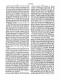
[57]
ABSTRACT
[21] APPL Nod 9131738
[22] Filed:
Jul. 14, 1992
Related U_S_ Application Data
_
A remotely programmable radiotelephone and a remote
'
programming unit. The radiotelephone (10) includes a
[63] commuanon of 5°“ No- 57918941 56P- 10’ 1990[51] Int. C1.5 .......................................... .. H04M 11/00
[52]
US. Cl. ...................................... .. 379/58; 379/63;
converter (31), a controller (50), and a memory (51).
379/355; 379/356
The converter (31) converts DTMF tones into digital
Field of Search ....................................... .. 379/57-
signals. The controller (50) monitors the output of the
U-S- PATENT DOCUMENTS
4,734.928 3/1988 Weiner et al. ...................... .. 379/59
mand. Certain commands must be preceded by the user
gnteging an access cfogirusins a control keypad (56) and
[58]
1561
receiver front end and demodulator (23), receiver signal
processing circuits (30), a dual-tone, multiple-frequency
4,803,717
2/1989 Marui .............. ..
379/67
4,837,800 6/1989 Freeburg CI 31
'
4,
’
,68
P
k
y t e reception 0
379/59
3332:’:' al"" "
9190
2211;251:313,-1:123:12:7253252332521:121i?
......... ..
in the memory (51) for later recall by the user. Other
....379 58
5,322,882 9239] Z‘i‘crk: et a]_ u
MP tones corresponding to a
password or security code stored in the memory (51).
Some commands cause telephone numbers to be stored
.
379;“
commands cause a number to be stored and an outgoing
5,097,502 3/1992 Suzuki et aL _
____ __ 379/356
5,109,403 4/1992 Sutphin ............................... .. 379/59
call to be automatically m1t1ated. The remote program
mmg capability allows a user’s secretary to cause the
FOREIGN PATENT DOCUMENTS
0176104 4/ 1986 European Pat. Off. .
radiotelephone (10) to place a call to a party speci?ed
by the user, and allows a dealer to reprogram operating
parameters and features of the radiotelephone (10) with
0206391 12/1936 European P?l- Off- ~
out the user having to come to the dealer’s place of
Link?" of Germany """ "
W081 /0282 4 10/1981 PCT
business. The remote programming unit provides for
"""""""" "
the-manual or computer-assisted programming of the
wow/01537 3/1987 PCT Int‘l App]. .......... .. H04B 7/14
WO88/l0039 12/1988 PCT Int'l Appl. .
2170977A
radlmelephme
8/1986 United Kingdom ...... .. HO4M 11/06
L\_.____.
I- 23
‘2L
2 Claims, 7 Drawing Sheets
“1
T 30
P.
__
_____
BSAI
I RECTEIVER _I__ RH-E'VEK
1
1_ anew, e1 ,0
I
I
I
I
I DEMODULATOE I
I
I
I
21
20
C'RCU‘TS’
35 I (54 I
(5‘
.31. 1
I 211112.115.‘ II
I
I
I 24
I
I
2“
l
1 RF sec'riou
|
I
mousse-ox) 25mm) |
v
I
25\
|
{:OHE
I llLlTERFkLE I r m
EWEMTOR
5r,
I
I
I
I gagrkor I
KEYPAD
I
I iilNSMlTTER
I
I
CONTROLLER MEMORY I
QMQRQ(ROM/RAM,
I
57
I
é_ 1:151:11." _I_@:I II
4T\ CONTROLLER I 58
I
I razusMn'rsak-l| eiacuws
S53E35“ ZTYQ‘I
I
I
l 419
I zzDUPLEXE
'?_\___
T s‘
CONTROL
SELTIOU
l
I
auoio SECTION
4%
______ -JJ?-LLJ
__
illI MILROPHONEII
R
|
| “SE
INTERFACE I
2%;
US. Patent
Jan. 4, 1994
\\\\
Sheet 5 of 7
5,276,729
|o\
UoQ\
RPu
RADWTELEPHOME
E; — 5A
L__/
l‘bl
‘O\
W?“
RPLL
‘Uh RADIOTELEPHOLIE
1742;’ — 5E5
Ll
"29A _____ __
uh ll-
RPu : ma“
I
|4:->_: ‘ox
4%
; RADIOTELEPHOME
|
L. ________ __..J
US. Patent
Jan. 4, 1994
Sheet 7 of 7
I40
5,276,729
flH
/
_:.H=U
5/
DUE
/
D
mm<
M.
i
@QQUD
.@
3 %.2@
@QQQQU...
m
w
m
w
.u
0J2x91mm5.,.
A
4
IJN
w
T0
.Mr
DD
.M
.l
w
m.
w;
i
mm. P#
3D
6Mm?nuu
wA
mJ
m
m.
Hi
DUm0v
Jill.#aw
A
C
D
B
(W
2.
.
1L4w.
J
Q.
040.
4/.
\M
$
%
mwD o
>/
A
J
STO
r
‘1:7
MENU )
1
5,276,729
2
tional areas, a different class of service, different operat
RADIOTELEPHONE FOR AUTOMATICALLY
DIALING REMOTELY PROGRAMMED NUMBER
UPON CALL TERMINATION AND WITHOUT
USER OPERATION
ing privileges, etc., are desired. The process of changing
any of these operating parameters is generally an incon
This is a continuation of application Ser. No. 579,894,
phone could be remotely programmed by the dealer.
venience to the user because the user must return to the
dealer to have the radiotelephone reprogrammed. It
would be more convenient for the user if the radiotele
?led Sep. 10, 1990.
Therefore, there is a need for a radiotelephone which
can be remotely programmed by a dealer so as to
TECHNICAL FIELD
l0 change the class of service, areas of service, and other
The present invention relates to radiotelephones and,
operating parameters. However, the radiotelephone
more particularly, to the remote programming and con
should prevent unauthorized persons from changing the
trol of radiotelephones by using standard DTMF tele
operating parameters.
phone tones.
Furthermore, in the case of a non-paying user or a
15 stolen radiotelephone, it is desirable to prevent the fur
BACKGROUND OF THE INVENTION
ther use of the radiotelephone. Therefore, there is a
Portable and mobile radiotelephones, once a rarity,
need for a radiotelephone which can be disabled by
have now become almost commonplace. Many users
remote control. However, the radiotelephone should
now ?nd a radiotelephone to be a personal and/or busi
prevent unauthorized persons from disabling the radio
ness necessity.
20
telephone.
However, the use of a radiotelephone when driving
can provide a safety hazard because the user must typi
This can make the user difficult to locate unless the user
cally look away from the road, toward the control key
pad, in order to dial the desired telephone number. This
has provided his/her secretary with a table listing the
system access telephone numbers for the different cities.
Many radiotelephone users travel to different cities.
brief inattention to the driving environment can cause 25 Furthermore, if the user is trying to call a party, who
has a radiotelephone, in another city then the user must
traffic. Of course, it is possible to provide speed dial
look through the book to determine the system access
functions so that the user may preprogram commonly
telephone number for that city. It would be advanta
an accident, especially in fast-moving and/or congested
called telephone numbers into a memory in the radio
geous if the radiotelephone would allow for the system
telephone and, when the user desires to place a call, the 30 access telephone number for commonly used cities to be
user simply punches in a smaller set of numbers, typi
programmed into the radiotelephone so that neither the
cally two or three digits, to cause the radiotelephone to
user nor the secretary had to look through the listings
extract the telephone number from the memory and dial
book. Therefore, there is a need for a radiotelephone
the desired telephone number. However, the user is still
which will store the system access telephone numbers
required to temporarily divert his attention to the con 35 for a plurality of cities.
trol keypad instead of to the driving environment. The
In addition, there is also a need for a device for re
diversion time is smaller, because of the reduced num
motely programming the radiotelephone. The device
ber of digits, but can still become signi?cant in many
must provide for convenient entry of any required pass
traffic situations. In addition, the user must be able to
words, access codes, security codes, instructions, etc.,
remember the speed dial bin corresponding to the de 40 and display responses and instructions from the radio
sired telephone number, must scroll through the speed
telephone.
dial bin numbers displayed on the control display (on
SUMMARY OF THE INVENTION
systems which provide this feature), or must have a
table which indicates the speed dial bin number for a
The present invention provides a radiotelephone
desired telephone number or desired party. However, 45 which is remotely programmable and controllable using
the latter two conditions still require the user to divert
attention from driving conditions and look at the con
trol display or the table. Also, the user must take the
time to program the radiotelephone.
dual-tone, multiple-frequency (DTMF) tones. A
The need for the user to divert his/her attention from
sequence of telephone numbers. Upon instruction by
driving conditions in order to dial a telephone number
would be eliminated if the user’s secretary could, from
the user, the secretary would look up the telephone
number or speed dial bin number for the desired party
and key in the command to dial that number using the
DTMF converter is used to convert DTMF tones into
digital signals which are acted upon by the controller in
the radiotelephone. This allows the radiotelephone to
Furthermore, depending upon the design of the ra 50 be remotely programmed and controlled. The control
diotelephone and the user’s manual dexterity, one or
ler inspects the DTMF tones received for the presence
both hands may be needed to initiate a call. This can
or absence of access and/or security codes and for the
, reduce the user’s ability to control the car or quickly
instructions that the controller is to execute. One level
respond to a changing traffic condition.
of access allows the secretary to cause the user’s radio
Many businessmen/businesswomen have a secretary. 55 telephone to dial a telephone number or a speci?ed
a remote location, cause the radiotelephone to dial the
desired telephone number. Therefore, there is a need for 60 DTMF keypad on the secretary’s telephone, thereby
causing the radiotelephone to dial the desired number.
This procedure requires minimum action on the part of
the user. The user could simply call the secretary using,
a radiotelephone which can be remotely controlled so
as to cause the radiotelephone to dial desired telephone
numbers with little or no action on the part of the user.
Typically, the radiotelephone is programmed by a
dealer to allow the use of speci?ed features and use in
prede?ned areas. However, many users travel through
one or more radiotelephone service areas in the course
of their personal/business affairs and may ?nd that addi
for example, a known speed dial bin or the user could
instruct the secretary to call the user at predetermined
times or at predetermined intervals.
This eliminates the need for the user to make any
keypad entries in order to implement a telephone con
3
5,276,729
4
versation. This allows the user to keep his/her eyes on
the road and hands on the steering wheel. The user can
therefore pay attention to the traf?c conditions and
.
TOMATIC ANSWER MODE OFF”, may be re
motely initiated.
Another feature of the present invention is that the
quickly respond to changing traffic conditions.
The present invention also allows the dealer to re
operating parameters may be changed only by a person
who knows the password.
motely program the radiotelephone. The dealer dials
the telephone number corresponding to that radiotele
operating parameters may be changed only after the
Another feature of the present invention is that the
phone or the user dials, or causes to be dialed, the tele
phone number of the dealer. After the user or dealer
answers the call the dealer enters a security code, the
user enters the required access code at the radiotele
user enters an access code, and the dealer then sends
tain features may be accessed only after the required
DTMF tones corresponding to the desired program
password has been entered at the radiotelephone or sent
ming instructions.
to the radiotelephone.
Another feature of the present invention is that the
phone.
Another feature of the present invention is that cer
The radiotelephone of the present invention includes
a radio frequency section, an audio section, a control 15 system access telephone number for a plurality of cities
section, and a user interface section. The RF section and
can be programmed into the radiotelephone. Therefore,
the user interface section are conventional in design.
if the user is going to a different city and wishes to leave
the system access telephone number for that city with
exception of the addition of a DTMF converter for
his/her secretary, the user simply scrolls through the
converting DTMF tones to digital signals. In addition, 20 ROAM memory bank to find the desired city and obtain
an external adapter provides a voice synthesizer, a mes
the system access telephone number for that city. This
sage player, and a hybrid and interface which provide
feature can also be used to initiate a call to the system of
The audio section is conventional‘ in design with the
for connection to an auxiliary device, such as a modem
or a facsimile machine. The voice synthesizer, message
a particular city so that the user can contact another
tions or data are valid and authorized. If the instructions
The standard DTMF tones are used to call the radio
party who also has a radiotelephone and is located in
player, and hybrid and interface may be internal to the 25 that city.
radiotelephone, if so desired. The control section is
Another feature of the present invention is a remote
conventional in design with the exception that the con
programming unit (RPU) which provides for conve
trolling microprocessor inspects the output signals from
nience in programming the radiotelephone. The RPU
the DTMF converter to determine if instructions or
provides the standard sixteen DTMF tones, twelve of
data are being provided and, if so, whether the instruc 30 which are typically found on conventional telephones.
or data and authorized then the controlling micro
telephone and control certain features of the radiotele
processor will respond using DTMF tones, store the
phone and the other DTMF tones are used to control
information in a memory, read information from the
other features and the operating parameters of the ra
memory, execute commands, and/or change the appro 35 diotelephone.
priate operating parameters of the radiotelephone.
BRIEF DESCRIPTION OF THE DRAWINGS
Therefore, one feature of the subject invention is that
the operating parameters of the radiotelephone may be
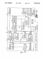
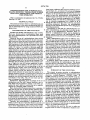
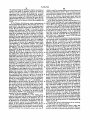
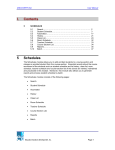
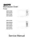
FIG. 1 is a block diagram of a radiotelephone which
remotely programmed by the dealer.
embodies the present invention.
Another feature of the present invention is that the
FIG. 2 is a block diagram of a Vehicle Adapter Unit
user’s secretary can program one or more telephone
used with the radiotelephone of the present invention.
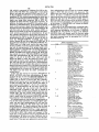
FIG. 3 is a block diagram of the preferred environ
numbers into the radiotelephone and cause the radio
telephone to begin dialing the first of these numbers
ment of the present invention.
FIG. 4 is a block diagram of the remote programming
provides for safety and convenience because the user 45 unit of the present invention.
does not have to divert attention from driving condi
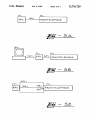
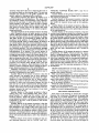
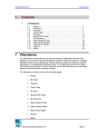
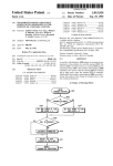
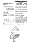
FIGS. 5A to SE illustrate various programming envi
tions in order to look up and/or dial a desired telephone
ronments for the radiotelephone.
number. This feature also provides for safety and con
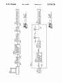
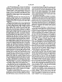
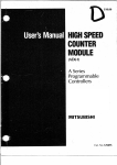
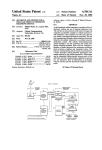
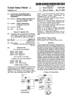
FIG. 6 is an illustration of a portable radiotelephone
venience because the user can continue to use both
installed in a remote programming unit.
without any action on the part of the user. This feature
hands to control the car.
Another feature of the present invention is that a
calling party may, using DTMF tones, enter a tele
phone number or a speed dial bin number, which is
stored in memory. Under the control of the user, the
50
DETAILED DESCRIPTION
Turn now to the drawing in which like numerals
represent like components throughout the several ?g
ures. FIG. 1 is a block diagram of a radiotelephone
stored telephone number is recalled and displayed and, 55 which embodies the present invention. The radiotele
if selected by the user, a call is placed to that stored
telephone number.
Another feature of the present invention is that the
user’s secretary, or another party with whom a call has
been established, may, using DTMF tones, enter a tele
phone number, or the number of a known speed dial bin
corresponding to the telephone number, which is then
stored in a scratchpad memory in the radiotelephone.
phone 10 has a radio frequency (RF) section 11, an
audio section 12, a control section 13, and‘ a user inter
face section 14. The RF section 11 is conventional in
design and includes a connector 20 for connecting ra
diotelephone 10 to an antenna 21, a duplexer 22, a re
ceiver front end and demodulator 23, and a transmitter
24, all of which are conventional in design. Duplexer 22
couples energy from transmitter 24 to an antenna, such
as antenna 21, and couples received signals from an
phone will automatically place a call to that telephone 65 antenna, such as antenna 21, to receiver front end and
number.
demodulator 23. Receiver front end and demodulator
Another feature of the present invention is that cer
23 tunes into the selected RF channel, amplifies the
Once the current call has been completed the radiotele
tain operating functions, such as “LOCK” and “AU
received signal, and demodulates the received signal to
5
5,276,729
recover the information contained in the modulated
6
49 and 50 are embodied as microprocessors. Memory 51
contains a ROM which has the operating instructions
for controller 50, a RAM which provides for the tempo
rary storage of information, and an electrically erasable
signal. This information is then provided to the receiver
signal processing circuits 30 in audio section 12. The
particular channel to which receiver front end and de
modulator 23 is tuned is determined by control signals
provided by control section 13 over signal path 25. The
transmitter signal processing circuits 32 of audio section
12 provides information to transmitter 24. Transmitter
programmable read only memory (EEPROM) which
provides for the storage of data which needs to be re
tained even when operating power is removed from
radiotelephone 10. The data may be, for example, au
thorized operating features or class of service, user-pro
24 contains an oscillator, a modulator, and a power
ampli?er. The particular RF channel on which trans
mitter 24 transmits the outgoing signal is controlled by
control signals provided by control section 13 over
grammed telephone speed dial numbers, security codes,
etc. Controller 50 and memory 51 are connected by bus
25. It will be appreciated that controller 50 may contain
signal path 25. Frequency modulation (FM) is the form
of modulation conventionally used for radiotelephones.
Audio section 12 contains receiver signal processing
circuits 30, a dual-tone, multiple-frequency (DTMF)
converter 31, transmitter signal processing circuits 32,
some or all of memory 51.
Controller 50 inspects digital signals on signal path 34
to determine whether these signals are instructions from
the MTSO or are noise. If the signals are instructions
then controller 50 responds in accordance with the
instruction, such as changing the current channel of
operation, signalling the user that an incoming call is
occurring, etc. Controller 50 also inspects the signals on
signal path 36 from DTMF converter 31 to determine
whether the signals are valid signals and, if so, whether
and a tone generator 40, which also generates DTMF
tones. Receiver signal processing circuits 30 are con
ventional in design and provide signal ampli?cation,
bandpass or lowpass ?ltering, recovery of control sig
nals provided'by the mobile telephone switching office
(MTSO), noise suppression, and muting of the informa
tion signal received from receiver front end and demod
ulator 23. A ?ltered, selectably muted and selectably
gain controlled audio signal is provided by receiver
signal processing circuits 30 over signal path 33A to
any instructions represented by the signals are autho
rized instructions. If valid, authorized instructions are
25 received in conjunction with any required access code
and/or security code controller 50 responds in accor
dance with these instructions. Controller 50 may per
speaker 54 of user interface section 14. Receiver signal
form such functions as storing telephone numbers in
processing circuits 30 also provides a ?ltered audio
memory 51, storing speed dial bin numbers correspond
signal to jack 48 via signal path 33B. This signal is se 30 ing to desired telephone numbers in memory 51, retriev
lectably muted and selectably gain controlled if handsf
ing telephone numbers from memory 51, initiating
ree operation has been selected. Receiver signal pro
placement of an outgoing call, storing new operating
cessing circuits 30 also provides digital output signals
information in memory 51, locking, unlocking, turning
over signal path 34 to controller 50 of control section
13. These digital signals provide supervisory and con
trol signals from the MTSO to the radiotelephone 10 for
such functions as: incoming call, call termination,
switch to a different channel, increase/decrease power
level, etc. Also, receiver signal processing circuits 30
off the power, etc.
35
Controller 50 also controls display devices 57 of user
interface section 14 by means of digital signals sent via
signal path 25 to controller 49. The information dis
played may be the channel number, the telephone num
ber, the speed dial bin number, the presence of an in
provides an audio signal, not subject to user volume 40 coming call, the status of the current call, the status of
control settings, over signal path 35 to DTMF con
the radiotelephone 10, such as locked, unlocked, etc.
verter 31. DTMF converter 31 converts DTMF tone
signals into digital signals and provides these digital
Controller 50 also inspects digital signals received
from controller 49 which corresponds to key entries
signals to controller 50. Under the control of controller
made using a user control device, such as control key
50, receiver circuits 30 selects a signal from receiver 45 pad 56 of user interface section 14. These digital signals
front end 23 or tone generator 40 and provides this
instruct controller 50 to perform such functions as:
selected signal to a selected one of speaker 54 or jack 48.
entering a new security code, unlocking, locking, caus
Transmitter signal processing circuits 32 receives
ing an incoming call to be answered, placing an outgo
voice signals from microphone 58 of user interface sec
ing call using a telephone number in memory 51 or a
tion 14 over signal path 37A, DTMF and other tone 50 telephone number provided by the user via control
signals from tone generator 40, and voice vand other
keypad 56, etc.
analog signals from jack 48 over signal path 37B, and
Interface 46 and jack 48 allow for controller 50 to be
receives control signals from controller 50 over signal
programmed directly using digital signals, rather than
path 25. The control signals on signal path 25 may be
by using DTMF signals. This allows radiotelephone 10
digital signals intended for the MTSO concerning such 55 to be programmed both on site and remotely. Interface
functions as: request to place an outgoing call, a tele
46 generally comprises buffers and any other circuits
phone number to be dialed, incoming call answered,
necessary to allow communication between controller
etc. The digital signals on signal path 25, the tone sig
50 and the device plugged into jack 48.
nals, the analog signals, or the voice signals, as selected
User interface section 14 contains a speaker 54, a
by controller 50, are provided by transmitter signal
control keypad 56, a display device 57, and a micro
processing circuits 32 to transmitter 24. Transmitter
phone 58. Controller 49 is connected to and controls the
signal processing circuits 32 also performs such func
operation of keypad 56 and display 57. For some radio
tions as bandpass or lowpass ?ltering for voice, tone,
telephones, particularly mobile radiotelephones which
and analog signals and signal waveform shaping for
digital signals.
Control section 13 includes a controller 50, a memory
51, an interface 46, a jack 48, and a keypad and display
controller 49. In the preferred embodiment, controllers
are installed in an automobile and which cannot also be
65 used as portable radiotelephones, user interface section
14 may be physically separate from the remainder of
radiotelephone 10 so that only user interface 14 is pres
ent in the passenger compartment of the vehicle.
7
5,276,729
FIG. 2 is a block diagram of the Vehicle Adapter
8
contains a standard DTMF telephone 101 which is
Unit (VAU) 60 used with the radiotelephone of the
connected by telephone link 102, typically a telephone
present invention. VAU 60 allows radiotelephone 10 to
trunk line, to the telephone company office 103. The
telephone company office 103 is connected by tele
phone link 104 to the mobile telephone switching office
(MTSO) 105, which includes antenna 106. Radiotele
be used as portable radiotelephone (portable mode)
when radiotelephone 10 is separate from VAU 60, and
as a mobile radiotelephone (mobile mode) when radio
telephone 10 is connected to VAU 60. It will be appre
ciated that VAU 60 is designed to be installed in a vehi
cle (not shown). For reasons of cost, weight, size,
power consumption, convenience in changing options,
and marketing considerations, voice synthesizer 63,
message player 64, hybrid and interface circit 65, and
phone 10 includes an antenna, such as antenna 21. To
establish contact, the user’s secretary may use telephone
101 to call the telephone number assigned to radiotele
10
phone 10. Telephone company office 103 and MTSO
105 then connect telephone 101 and radiotelephone 10.
jack 66 are placed in VAU 60 instead of in radiotele
Also, the user may use radiotelephone 10 to place a call
to the user’s office 100. Once contact has been estab
phone 10. However, if desired, these components may
be placed in radiotelephone 10. Also, if desired, DTMF
lished the user’s secretary will use telephone 101 to key
in the telephone number, or the corresponding speed
converter 31 may be part of VAU 60. In this case, radio
telephone 10 will only be remotely programmable when
it is installed in VAU 60.
dial bin number, of the party or parties that the user
desires to call. Telephone numbers and bin numbers are
entered using the format: ‘+NUMBER+#. In the
VAU 60 has a plug 61, which makes mechanical and
preferred embodiment radiotelephone 10 has 200 speed
electrical contact with jack 48 when radiotelephone 10 20 dial bins. Therefore, a number between 0 and 199 will
is inserted into the cradle 62 of VAU 60. VAU 60 also
be treated as a bin number and any other number will be
has a power switch (not shown) and, via plug 61, pro
treated as a telephone number. Radiotelephone 10 will
vides operating power to radiotelephone 10 when ra
also check the speci?ed bin to verify that a telephone
diotelephone 10 is installed in cradle 62. Controller 50
number is located in the speci?ed bin. Radiotelephone
controls the operation of and/or receives status infor 25 10 will acknowledge the entry of the # key, which
mation from voice synthesizer 63, message player 64,
signifies the end of the number, by sending a short tone.
hybrid and interface circuit 65, handsfree microphone
70, and handsfree speaker 71, via signal path 47, jack 48,
plug 61, and signal path 47’. Message player 64, voice
synthesizer 63, hybrid and interface circuit 65, and
handsfree microphone 70 send voice and other analog
signals to transmitter signal processing circuits 32 via
signal path 37B’, plug 61, jack 48, and signal path 37B.
Similarly, receiver signal processing circuit 30 sends
voice and other analog signals to hybrid and interface
circuit 65 and handsfree speaker 71 via signal path 33B,
jack 48, plug 61 and signal path 33B‘. Duplexer 22 is
connected by signal paths 26 and 26', jack 48, and plug
These numbers are stored in memory 51 in a predeter
mined memory area, such as a scratchpad memory.
In the preferred embodiment up to 5 telephone num
bers and/or bin numbers may be entered. After the fifth
number has been entered the old numbers are replaced
by new numbers on a first in/?rst out basis.
As the last number is entered two different modes of
operation are possible: manual dialing, and automatic
35 dialing. For the manual dialing mode the user’s secre
tary simply hangs up after entering the last number and
61 to connector 72, whereby radiotelephone 10 is
the user must cause the radiotelephone 10 to place the
call. Each time the user presses the SEND key one of
the numbers will be called, ori a last in/?rst out basis.
switched from antenna 21 to a mobile antenna (not
Also, using control keypad 56 and display device 57, the
shown) installed on the vehicle in which VAU 60 is
user may scroll through the numbers and place the calls
in any desired order. For the automatic dialing mode
installed.
Hybrid and interface circuit 65 and RJ-ll jack 66
provide for the connection of an auxiliary device (not
the user’s secretary enters a “0" after the “#” has been
entered (‘+NUMBER+#+O), hangs up, and radio
shown), such as an answering machine, a facsimile ma 45 telephone 10 will proceed to automatically place the
chine, or a modern, so that the auxiliary device can be
calls. Each time a call is completed, as indicated by the
used and, in the Data AutoAnswer mode, can answer an
user pressing the END key, radiotelephone 10 will
incoming call. When in the Data AutoAnswer mode
place a call to the next number in the memory. In an
controller 50 will cause hybrid 65 to provide standard
alternative embodiment, radiotelephone 10 will also
place the next call in response to the MTSO 105 sending
ringing signals on jack 66 is response to signals from the
MTSO that an incoming call is present. Hybrid 65 will
signal controller 50 over bus 25 if the auxiliary device
an indication that the current call has been terminated.
goes off-hook. Controller 50 will then cause hybrid 65
to connect receiver circuits 30 and transmitter circuits
which are user selectable using control keypad 56. The
four operating modes are mutually exclusive and are as
Radiotelephone 10 has four primary operating modes
32 to the auxiliary device. The incoming call is thereby 55 follows: AutoAnswer Off; Voice AutoAnswer; Ab
connected to the auxiliary device. Hybrid 65 will signal
sence AutoAnswer; and Data AutoAnswer. Whenever
controller 50 when the auxiliary device goes onhook.
power is turned off and then back on radiotelephone 10
Controller 50 will then send a disconnect signal to the
will automatically, by default, enter the AutoAnswer
MTSO and cause hybrid 65 to disconnect the auxiliary
device from circuits 30 and 32. Also, if the MTSO sends
Off mode, wherein the user must press a key or take
some action to answer an incoming call. In the Voice
a disconnect or call termination signal then controller
50 will cause hybrid 65 to disconnect the auxiliary de
display 57 will flash, the incoming call is automatically
AutoAnswer mode the incoming call indication on
vice from circuits 30 and 32. The design and construc
answered on the programmed ring number, and the
tion of hybrid circuits and interface circuits which per
answer of the call is announced by a beep through
form the functions of hybrid and interface circuits 65, as 65 speaker 54 (portable mode) or speaker 71 (mobile
described above, are well known.
mode). Speaker 54 and microphone 58 (portable mode)
FIG. 3 is a block diagram of the preferred environ
or speaker 71 and microphone 70 (mobile mode) then
ment of the present invention. The user's office 100
are automatically activated. The user may also answer
9
5,276,729
the call by pressing the SEND key before AutoAnswer
occurs. This mode of operation requires no action by
Absence AutoAnswer mode. These scratchpad areas
were arbitrarily selected to store 5 numbers for secretar
ial access and 9 numbers for the Absence AutoAnswer
mode. In the Absence AutoAnswer mode, after the
the user in order to answer an incoming call. It will be
appreciated that controller 50 performs the AutoAn
swer action in response to a signal from MTSO 105 that
there is an incoming call. Controller 50 causes the dis
play 57 to ?ash and causes tone generator 40 to generate
scratchpad area has been ?lled, radiotelephone 10 will
not automatically answer any other calls.
the beep and send the beep to circuits 30 and speaker 54
In the Data AutoAnswer mode controller 50 will, in
response to an incoming call, cause ringing signals to be
or 71.
In the Absence AutoAnswer mode, radiotelephone
sent to speaker 54 and will cause hybrid and interface
circuit 65 to send ringing signals to an auxiliary device
connected to jack 66. If the auxiliary device goes off
hook controller 50 will notify MTSO 105 that the call
has been answered and will then route all audio signals
to and from the auxiliary device. Also, as previously
10 will automatically answer the incoming call on the
programmed ring number. If optional message player
64 or voice synthesizer 63 has been installed then con
troller 50 will cause a message to be played which
prompts the calling party to key in his/her telephone
number, followed by the # key. If neither voice synthe
described, when the calling party or the auxiliary de
vice goes on-hook controller 50 will disconnect the
audio path and, if appropriate, signal MTSO 105 that
sizer 63 nor message player 64 is installed, or if radio
telephone 10 is in the portable mode, then radiotele
phone 10 will send a three-burst tone, signifying that the
incoming call has been answered. If optional synthe
sizer 63 has been installed then, after the telephone
number has been entered by the calling party, controller
50 will cause synthesizer 63 to generate spoken words
corresponding to the telephone number. The calling
party may signify an incorrect telephone number by
pressing the * key and re-entering the telephone num
ber. Message player 64 and voice synthesizer 63 may,
along with the greeting message, provide instructions
regarding correcting an incorrect telephone number.
Controller 50 will cause a single-burst tone to be sent to
the calling party after the entry of a * or a #. In one
embodiment, controller 50 will check the bin number to
verify that a telephone number is stored there. If a tele
phone number is not present controller 50 will cause a
10
which is used for storing numbers provided during the
the call has been terminated.
In both the Absence AutoAnswer mode and the Data
AutoAnswer mode, controller 50 will cause the incom
ing call indicator on display 57 to flash, cause tone
generator 40 and receiver circuits 30 to send ringing
signals to speaker 54, to signify the user that an incom
25 ing call is occurring, and, upon an AutoAnswer, cause
20
a single beep to be sent to speaker 54 to indicate that an
AutoAnswer has occurred. The user may, at any time,
press the SEND key on keypad 56 and controller 50
will then immediately reroute the audio signals to con
nect speaker 54 and microphone 58, or handset 55, or
speaker 71 and microphone 70, as selected by the user.
In the preferred embodiment, the user may remotely
lock and turn off the AutoAnswer mode of radiotele
phone 10 provided that radiotelephone 10 is in an Au~
three-burst error tone or a message to be sent to the 35 toAnswer mode or if someone answers the call to radio
calling party advising that the speed dial bin number is
telephone-10. The user will, using a DTMF telephone
such as telephone 101, call the telephone number for
incorrect. If a telephone number is present in that bin
controller 50 will cause synthesizer 63 to generate spo
radiotelephone 10 and, upon an answer or an AutoAn
ken words corresponding to that bin number or corre
swer, enter the desired remote command. The remote '
sponding to the telephone number stored in that bin. 40 LOCK command is '+# +UNLOCK CODE-+5, and
The calling party may signify an error by pressing the *
activates the lock feature. When locked and in an Au
key and then re-enter the bin or telephone number if the
toAnswer mode, radiotelephone 10 will allow incoming
number was incorrect. After the calling party has en
calls to be answered but will not allow outbound calls to
tered his/her telephone number, or speed dial bin num
be originated. When locked and in the AutoAnswer Off
ber, controller 50 will cause the number to be stored in 45 mode, radiotelephone 10 will not allow incoming calls
a predetermined area of memory 51, such as a scratch
pad memory. The calling party may enter the telephone
to be answered or outbound calls to be originated. The
remote AutoAnswer off command is * + # +UNLOCK
number or speed dial bin number in either of the follow
CODE+2, and sets radiotelephone 10 to the AutoAn
swer off mode. Radiotelephone 10 acknowledges the
Radiotelephone 10 will display, at display 57, the num 50 commands by sending a short tone after the ‘, #, the
ber of calls answered by radiotelephone 10. The user
UNLOCK CODE, and the number 5 and the number 2.
can return the calls by scrolling through the list of num
The UNLOCK CODE is required to be entered in
bers and calling only those numbers of interest in any
order to prevent an unauthorized person from locking
desired order. The user can view the numbers by press
and/or tampering with radiotelephone 10. The UN
ing RECALL+'+'+", and using VOLUME UP and 55 LOCK code therefore functions as a user access code.
ing formats: NUMBER+#; and "+NUMBER+#.
VOLUME DOWN. The number can be called by the
user pressing “SEND”, and can be stored in scratchpad
In the preferred embodiment, the UNLOCK is a user
programmable code of l to 8 digits. If the remote Au
memory by the user pressing “STORE”.
In the preferred embodiment, if the calling party
toAnswer off command is given when radiotelephone
10 is in the mobile operating mode and either the Mes
entered a valid speed dial bin number controller 50 will
cause the telephone number to be displayed. If an in
valid bin number was entered then the bin number will
sage AutoAnswer mode or the Data AutoAnswer mode
has been activated then the AutoAnswer feature will be
turned off and operating power for radiotelephone 10
be displayed. In an alternative embodiment, only the
will be turned off.
number actually entered by the calling party is dis
The user may unlock radiotelephone 10 by entering
played. In the preferred embodiment memory 51 in 65 the UNLOCK code using keypad 56.
cludes the speed dial bins described above, as well as the
In the preferred embodiment the dealer’s office 107
two scratchpad areas, one of which is used for storing
numbers provided by secretarial access, and one of
contains a least a standard DTMF telephone 109 con
nected by line 110 to a remote programming unit (RPU)
11
5,276,729
12
111, which is connected by telephone link 112 to tele
then radiotelephone 10 will send the VALID CODE
phone office 103. RPU 111, as described in more detail
signal to RPU 111 and store the new password. The
below, can send and received DTMF tones (0-9,‘, #,
dealer may then enter the dealer commands described
A-D), and display codes sent to or received from radio
below. If there is a difference between the ?rst new
telephone 10. For remote programming the dealer and 5 password and the second new password then radiotele
the user of radiotelephone 10 will establish contact. The
phone 10 will send the INVALID CODE signal to ‘
dealer can, using either telephone 109 or RPU 111,
RPU 111. RPU 111 will then advise the dealer to repeat
perform the same functions as the user’s secretary. In
the new password procedure. The password is entered
addition, the dealer can, using RPU 111, perform other
in the format ‘+PASSWORD+#, where the PASS
functions, as described below. In the preferred embodi
WORD must be 10 digits.
ment, to allow access to dealer functions, the dealer will
After each of the following dealer commands radio
send the Service Command (D+#). Radiotelephone 10
telephone 10 will respond with either the OK code or
will then send its electronic serial number (ESN) to
with requested information, in the format ‘+INFOR
RPU 111. The ESN can be used to determine the autho
MATION+#. The number of digits in the INFOR
rized operating parameters of radiotelephone 10 and
MATION ?eld will depend upon the function being
also whether radiotelephone 10 has been reported to be
performed. The dealer commands are listed in the table,
a stolen unit. In response to the Service Command ra
and each command must be proceeded by ‘+D+A
diotelephone 10 will, via display 57, advise the user to
and followed by #.
enter the PROGRAMMING ACCESS code using
control keypad 56, and then press the STORE key. In 20
Dealer Commands/Functions
the preferred embodiment the PROGRAMMING AC
Code
Function
CESS code is a 9-digit code, such as the user‘s social
security number or driver’s license number. This code
can only be reprogrammed if the proper dealer com
mand is entered. Controller 50 will compare this PRO 25
GRAMMING ACCESS code with the PROGRAM
MING ACCESS code stored in memory 51. If the user
has entered the correct PROGRAMMING ACCESS
Speed Dial Memory Clear.
2
Reset, to default value, user
programmable functions,
such as volume level of
ringer, type of ringing tone,
display selection, etc.
Read Number Activation
Module(NAM) information
code then radiotelephone 10 will send an OK (valid)
signal ("+D+#) to the RPU 111, which will then 30
where N equals l-S for each
NAM, and Y equals l-9 for
each parameter.
Write NAM information,
where N equals l-5 for each
NAM, X equals 1 for a
telephone number and X
equals 2 for a System
advise the dealer to enter the password, which is an
other type of security code, using the keypad on RPU
111. RPU 111 will send this password to radiotelephone
l0. Controller 50 will compare this password with the
password stored in memory 51. If the dealer has entered 35
a valid master password or a valid dealer password then
Identi?cation Number (SID),
radiotelephone 10 will send the OK signal to RPU 111.
The dealer may then enter the dealer commands de
scribed below.
and I equals up to 10 digits
for a telephone number. and
I equals 5 digits for a SID.
Reset dealer password to
default password. This
function is accessible only if
5
If the user has entered an incorrect PROGRAM’
MING ACCESS code then radiotelephone 10 again
the master password was used
prompts the user to enter the PROGRAMMING AC
CESS code. If an incorrect PROGRAMMING AC
CESS code is entered a second time then radiotele
phone 10 will send an error (invalid) signal (*+A+#)
for access.
6
Read Call Restriction Level,
such as: no restriction, no
incoming calls, no outgoing
calls from keypad
(outgoing call from speed
45
to RPU 111. RPU 111 will then prompt the dealer to
send a dealer LOCK signal (“+#+D+5) to radiotele
dial memory only), no long
distance calls (local, 800, or
0 + only), etc.
Write Call Restriction
Level, where Z equals a 4
phone 10. Radiotelephone 10 will then execute the
LOCK command and stay locked until the correct
UNLOCK code is entered by the user. It should be 50
noted that dealer LOCK code is different than the user
LOCK code. The user LOCK code requires that the
correct UNLOCK code be known. The dealer LOCK
code is useful when an incorrect UNLOCK code has
55
been entered or the UNLOCK code is not known.
If a default password was sent but is inappropriate or
8
digit call restriction code.
Read multiple NAM
programming.
Write multiple NAM
programming, where M
equals 0-5 for the multiple
NAM setting, such as:
if an invalid master password or an invalid dealer pass
multiple NAM with
word was sent then radiotelephone 10 will send the
error signal to RPU 111. The dealer may then enter
another password. If a dealer password has not been
automatic NAM selection,
NAM 1 only, NAM 2 only,
programmed into radiotelephone 10 then the factory
etc.
0
Read A/B System Setting,
such as: use System (Carrier)
installed default password will be a valid password.
Radiotelephone 10 will then send a PASSWORD signal
('+B+#) to RPU 111, which will indicate to the
A only, use System B only,
dealer that a new password must be programmed into 65
radiotelephone 10 before any other functions can be
where P equals 0-5 for the
accomplished. The dealer is requested to enter the pass
word twice. If the same new password is entered twice
use system A if possible, use
System B if possible, etc.
Write A/B System Setting,
system setting. and 5 equals
the 5~digit SID.
13
5,276,729
The NAM parameters are: a system access telephone
number, a system identi?cation number, an initial pag
ing channel, an access overload control, a group identi
ers and any other circuits necessary to allow communi
cation between RPU 111 and radiotelephone 10. Plug
143 is inserted into jack 48 of radiotelephone 10. This
allows for the direct programming of the radiotele
phone. In the preferred embodiment, when jack 48 is
used for programming radiotelephone 10, it is still nec
essary to know the security code or passwords in order
?er, a station class, options, and security codes. In the
“NAM X ONLY” mode radiotelephone 10 will only
use the system access telephone number speci?ed in
NAM X. In the “Automatic NAM Selection” mode
radiotelephone 10 may use the system access telephone
number in any NAM, subject to the A/B System Set
ting restriction.
As previously described, other parties may also leave
telephone numbers for the user via radiotelephone 10.
Other panties 113A-113N each have a standard DTMF
telephone 114A-114N respectively, which is connected
to telephone office 103 via a telephone link 115A-115N,
respectively.
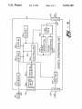
FIG. 4 is a block diagram of the remote programming
unit (RPU) of the present invention. RPU 111 includes
14
and a plug 143. Interface 127 generally comprises buff
10
to accomplish programming.
'
If an external device, such as a modem or a computer,
is plugged into jack 140 and plug 143 is inserted into
radiotelephone 10, protocol converter 129 provides any
necessary conversion between the protocol used by the
external device and the protocol used by radiotele
phone 10. In this case, controller 120 does not perform
any protocol conversion. However, it will be appreci
ated that the function of protocol converter 129 may be
performed by controller 120 if desired so that converter
a controller 120 connected by signal path 121 to a mem
129 may be eliminated and interface 130 connected
ory 122, a DTMF generator 123, a DTMF converter 20 directly to bus 121.
124, a display 125, a keypad 126, an RPU-radiotele
phone interface 127, a protocol converter 129, a tele
phone line switch 131, and a telephone line interface
133. Protocol converter 129 is connected to an RS-232
interface 130. Telephone link 112 is connected to tele
phone signal bus 134 of RPU 111 through jack 135.
In the preferred embodiment a speed dial bin will
have an alpha numeric name ?eld, as well as a telephone
number ?eld. It is possible, but cumbersome, to send
both alpha characters and numbers by using the limited
number of standard DTMF tones. Therefore, in the
preferred embodiment, the commands to read the con
tents of a speed dial bin and to write to a speed dial bin
Switched telephone line 110 is connected to telephone
bus 134 through jack 137 and switch 131. In the pre
are only valid when radiotelephone 10 is installed in
ferred embodiment, jacks 135 and 137 are RJ-ll jacks.
Telephone jack 137 and bus 134 are selectably con 30 RPU 111. In an alternative embodiment, a speed dial bin
number and a telephone number may be programmed
nected and disconnected by switch 131, which is con
using DTMF tones. A speed dial bin may be pro
trolled by controller 120. Switch 131 allows controller
grammed by the user’s secretary using the format:
120 to isolate telephone 109 when RPU 111 is conduct
"+“+BIN NUMBER+"+TELEPl-IONE NUM
ing reprogramming of radiotelephone 10, and to con
nect telephone 109 to telephone link 112 when RPU 111 35 BER+#. Radiotelephone 10 will acknowledge entries
as previously described. In another alternative embodi
is not conducting reprogramming. Line interface 133 is
ment, the name ?eld may also be programmed using
connected to telephone signal path 134, is conventional
DTMF tones. This allow the user’s secretary to pro
in nature, and performs such functions as seizing the
gram frequently used telephone numbers into radiotele
telephone line, electrically isolating the telephone line
112 from RPU 111, voltage surge limiting, sending and
receiving signals on telephone line 112, and ring detec
40 phone 10. The user’s secretary can cause radiotelephone
10 to call the desired number, as described above, or the
user may enter the bin number, thereby causing the
radiotelephone 10 to retrieve the telephone number at
that bin and place a call to that number.
under the direction of controller 120. Components 123,
In the preferred embodiment, memory 51 also has
124 and 133 allow controller 120 of RPU 111 to com 45
thirty ROAM access bins, which are similar to speed
municate with controller 50 of radiotelephone 10 by
dial bins and may, if desired, be part of the speed dial bin
using DTMF tones. Display 125 allows controller 120
tion. DTMF generator 123 and DTMF converter 124
are selectably connected by line interface 133 to bus 134
to prompt the dealer as to the next action to be taken, to
function. Each ROAM access bin has an alpha numeric
display signals being sent to radiotelephone 10, and to
display to the dealer the meaning of signals received
from radiotelephone 10. Keypad 126 allows the dealer
to input commands and data to be provided by control
ler 120 to radiotelephone 10. Memory 122 contains
operating instructions for controller 120 and also stores
city name ?eld, as well as a ?eld for a system access
50 telephone number for that city. If the user is going to
city A and then city B the user will scroll through the
ROAM access bins, ?nd city A and city B, and provide
the telephone numbers to his/her secretary. The secre
tary will then be able to quickly establish a call to the
data received from or to be sent to radiotelephone 10. 55 user via the system access number for that city. Also, if
the user knows that the party to be called is in city C,
Controller 120 is a microprocessor and may, as part
the user will scroll through the ROAM access bins, ?nd
of its design, contain some or all of memory 122.
city C, and press “SEND”. This will connect the user
For some functions, such as programming a number '
with the system for city C so that the user can the dial
of speed dial bins, the use of keypad 126 may be too
slow. Therefore, RPU 111 has an RS-232 interface 130 60 the number of the party to be called.
which is connected to an RS-232 connector 140. This
allows for the control of RPU 111 and programming of
radiotelephone 10 by using a computer or a modem.
To program the ROAM access bins the user presses
“ALPHA” and “STORE”, scrolls (volume up or vol
ume down) to the desired bin, enters the ROAM access
This is shown in more detail below.
number, presses “STORE”, enters the city name, and
In addition, especially where radiotelephone 10 is a 65 presses “STORE’”. The user then scrolls to the next
portable unit, it may be desirable to program radiotele
desired bin to program the information for the next city.
phone 10 directly, rather by using DTMF tones. There
When programming is complete the user presses and
fore, RPU 111 also contains an interface 127, a bus 142,
holds “CLEAR" to exit the programming mode.
15
5,276,729
To review the information the user presses “RE
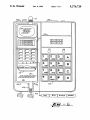
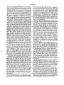
16
into jack 48 of radiotelephone 10. Also shown are the
CALL”, presses the “"‘ key four times, and then
speaker 54, microphone 58, keypad 56, display 57, and
presses “RECALL”. The user can then scroll (volume
antenna 21 of a portable radiotelephone 10.
It should be noted that keypad 126 of RPU 111 con
up or volume down) through the bins, press "SEND” to
call that city, or press “RECALL" to exit the review
mode.
In the preferred embodiment, the ROAM access bins
are programmed using keypad 56 of radiotelephone 10
or by installing radiotelephone 10 into an RPU 111. It is
possible, but cumbersome, to send both alpha characters
and numbers by using the limited number of standard
DTMF tones. However, in an alternative embodiment,
a ROAM access bin number and a telephone number
tains keys for the standard DTMF tones as well as the
DTMF tones A, B, C and D. The keypad 56 for radio
telephone 10 has standard DTMF keys 0-9, *, and #, as
well as keys for the following functions: SEND,
CLEAR, END, RECALL, STORE, MENU, and AL
PHA. Displays 57 and 125 are eight character, two-line
displays. In addition, display 57 has indicator lights for
the following conditions: received signal strength, in
use, service not currently available, roaming in an “A”
may be programmed using DTMF tones. In another
system,
roaming in a “B” system, AutoAnswer mode
alternative embodiment, the city name may also be a 5
on, menu review, and alpha character entry review
programmed using DTMF tones.
mode on. Display 125 also contains a TX indicator light
FIGS. 5A 5E illustrate various programming envi
and an RX indicator light, which show when RPU 111
ronments for radiotelephone 10. FIG. 5A shows RPU
is sending data to radiotelephone 10 and receiving data
111 connected by signal path 160 to radiotelephone 10.
from radiotelephone 10, respectively. RPU 111 has a
FIG. 5B shows a personal computer 161 connected by
cradle 180 in which radiotelephone 10 is placed for on
signal path 162 to jack 140 of RPU 111, which is con
site programming.
nected by signal path 160 to radiotelephone 10. FIG. 5C
It will be appreciated from the above that radiotele
shows a personal computer 161 connected by signal
phone 10 is remotely programmable and operable to
path 162 to a modern 164, which is connected by tele
phone link 165 to telephone company of?ce 103, which 25 receive and store numbers for the user to call as well as
for automatically initiating the placement of these num
is connected by telephone link 166 to modern 167,
bers. Furthermore, by using the proper access codes
which is connected by signal path 170 to jack 140 of
and passwords, the status (lock, AutoAnswer Off) and
RPU 111, which is connected by signal path 160 to
other operating parameters may be remotely pro
radiotelephone 10. FIG. 5D shows that, in one applica
tion, signal path 160 includes conductor 164 and plug
143, which is plugged into jack 48. FIG. 5E shows that,
in another application, signal path 160 includes a tele
phone link 112 connected between jack 135 of RPU 111
grammed and controlled. The use of the access codes or
passwords prevents unauthorized persons from interfer
ing with the programming and operation of radiotele
phone 10. It will be appreciated from the description
and a telephone company office 103, which is con
above that the user‘s secretary may send desired tele
nected by signal path 104 to MTSO 105, which is con 35 phone numbers and instructions to radiotelephone 10 so
nected to antenna 106. Antenna 21 is connected to ra
that the user is neither required to manually key in the
diotelephone 10. FIG. 5A therefore shows the use of
telephone numberor even a corresponding speed dial
RPU 111 to directly or remotely program radiotele
bin number. Radiotelephone 10 also provides for the
phone 10. FIG. 5B shows the use of a personal com
‘automatic initiation of dialing of stored telephone num
puter 161, in conjunction with RPU 111, to directly or
bers and for the manual initiation of the dialing.
remotely program radiotelephone 10. FIG. 5C shows
It will be appreciated from the above that the present
that a personal computer, located remotely from RPU
invention is a radiotelephone which can be remotely
111, may be used to directly or remotely program radio
programmed and controlled using standard DTMF
telephone 10.
tones and which provides for the use of access codes
Of course, it will be appreciated that the program for 45 and passwords so as to prevent unauthorized persons
personal computer 161 must understand the meaning of
signals from RPU 111, display these signals to the user,
accept user entries from a keypad associated with com
puter 161, and translate these signals into a form recog
nizable by RPU 111. For example, the computer key
board entry “S" followed by a carriage return may
mean: Read Call Restriction Level. RPU 111 would
therefore send to radiotelephone 10 the corresponding
remote command, or commands, using DTMF tones or,
if radiotelephone 10 is installed in RPU 111, RPU 111 55
would send the corresponding sequence of serial data
signals via plug 143. For reasons of security and/or
convenience in use, some commands may only be sent
when radiotelephone 10 is installed in RPU 111. In
applications where a computer 161 is used RPU 111
functions simply as a protocol converter in FIG. 5D, or
as a DTMF generator/receiver in FIG. 5B, between
the computer 161 and radiotelephone 10.
FIG. 6 is an illustration of a portable radiotelephone
from altering the programming of the radiotelephone. It
will be appreciated that the present invention also in
cludes a programming unit for programming the radio
telephone. From the detailed description above and the
accompanying drawings variations of the present inven
tion will suggest themselves to those of skill in the art.
Therefore, the present invention is to be limited only by
the claims below.
We claim:
1. A radiotelephone, comprising:
transmitter means for providing a modulated transmit
signal;
receiver means for providing a demodulated signal in
response to a received signal;
tone converter means for providing digital signals
corresponding to dual-tone, multiple-frequency
(DTMF) tones contained in said demodulated sig
10 installed in a remote programming unit 111. RPU 111
nal, said DTMF tones corresponding to a tele
phone number and an instruction to automatically
has a control keypad 126, a display 125, a line jack 135,
a telephone jack 137, an RS-232 jack 140, a connecting
cable 142, and a plug 143. Plug 143 is shown inserted
and said instruction being provided by a connected
party during a ?rst call; and
dial said telephone number, said telephone number
17
5,276,729
18
providing digital signals corresponding to dual-tone,
control means comprising a processor and a memory
for storing operating instructions for said proces
multiple-frequency (DTMF) tones contained in
sor;
said demodulated signal, said DTMF tones corre
sponding to a telephone number and an instruction
wherein said processor responds to a predetermined
set of said digital signals when a user is present by 5
storing said telephone number and, upon comple
tion of said ?rst call, by causing said transmitter
means to automatically place a second call, without
a dialing operation by said user, to said telephone 10
number by sending a said modulated transmit sig
nal corresponding to said telephone number to be
called.
2. A method for operating a radiotelephone, said
method comprising the steps of:
providing a demodulated signal in response to a re
to automatically dial said telephone number, said
telephone number and said instruction being pro
vided by a connected party during a first call; and
when a user is present, responding to a predetermined
set of said digital signals by causing said radiotele
phone to store said telephone number and, upon
completion of said ?rst call, causing said radiotele
phone to automatically place a second call, without
a dialing operation by said user, to said telephone
number by sending a modulated transmit signal
corresponding to said telephone number to be
called.
ceived signal;
‘
20
25
30
35
45
50
55
65
t
t
i
Q