1
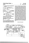
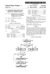
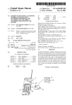
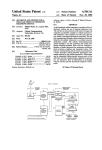
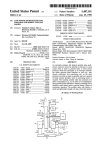
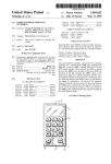
llllllllllllllIIIlllllllllllllllllllllllllIllllllllllllllllllllllllllllllll
USOO5l75759A
United States Patent [19]
[11]
Patent Number:
Metroka et a1.
145]
Date of Patent:
[54] COMMUNICATIONS DEVICE WITH
FOREIGN PATENT DOCUMENTS
MOVABLE ELEMENT CONTROL
INTERFACE
[76]
9010340
Inventors: Michael P. Metroka, 730 Oakview
Dr., Algonquin, 111. 60102; Robert K.
Krolopp, 6466 Cape Cod CL, Lisle,
111. 60532
Nov. 20, 1989
[51]
Int. Cl.5 .......................................... .. H04M 11/00
[52]
US. Cl. ...................................... .. 379/58; 379/61;
379/63; 455/89; 381/43
[58]
9/1990
PCT Int’l App]. ................. .. 379/58
OTHER PUBLICATIONS
Motorola, “V. S. P. Hands-Free Operation Board”,
68P81048E93-A Jun. 15, 1983.
Motorola, “Dyna-Tac 6000X”, 1984.
Systcoms “Systcoms Classic Series”, Telephony Jan.
[21] Appl. No.: 439,983
[22] Filed:
5,175,759
Dec. 29, 1992
Field of Search ................... .. 379/58, 63, 433, 62,
379/67, 56, 61; 362/24; 364/707; 455/90, 89,
73; Dl4/138; 340/825.44, 825, 825.36; 371/66;
381/43, 40, 110, 41
28, 1990.
Realistic Owner’s Manual: Duofone ET—415 Cordless
Electronic Telephone: Cat. #43-444: 1984.
Motorola, Inc., User’s Manual #68P81121E820: Digital
Voice Caller, Sep. 1988.
Motorola, Inc. Manual #68P81115E38-D “VSP Hand
s-Free Optics-Model T375A Series”, Nov. 5, 1985.
Motorola, Inc. Manual #68P81117E63-O “VSP 11
References Cited
Hands Free Option”, Model No. T944 Series Nov. 8,
1965.
Panasonic KX-T300 Easa-Phone Cordless Phone FCC
U.S. PATENT DOCUMENTS
Transmitter Type Acceptance Filing Exhibits B, E, F
[56]
D. 300.742
4/1989
Soren et al. ..................... .. D14/l48
D. 304.189 10/1989 Nagele et al. ..
D. 305,427 l/1990
3,476,886 ll/1969
3,551,607 12/1970
3,962,571 6/1976
4,018,998
4/1977
D14/l47
Soren et a1. ..................... .. D14/138
Ferrari et a1. .
Tommasi et a1. .
Brantingham ..................... .. 364/707
Wagner ........ ..
Mallien .... ..
379/63
4,124,879 11/1978
Schoemer .... ..
362/24
4.471.493
Schober
.. .. . . ... . . . .
. . . . . . ..
379/61
4,477,807 10/1984
Nakajima et a1. .
4,680,787
6/1987
Marry
4.737.975
4/1988
Shafer .......... ..
4,797,929
l/l989 Gerson et a1.
381/43
4,845,772
4,870,686
7/1989
9/1989
Metroka et a]. ........ ..
Gerson et a1. .......... ..
379/61
381/43
4.893.348
4,896.361
1/1990
Andoh ......... ..
455/89
1/1990
Gerson ......... ..
381/40
4,897,873
1/1990
Beutler et a1. .
379/433
... .. . .. .. . . . .. .
4,933,963
6/1990 Sato et a1.
4,945,570
4,959.850
7/1990
9/1990
340/825.44
. . . . . . ..
379/58
381/110
379/58
4,961,212 10/1990 Marui et al.
379/67
5,023,911
6/1991
5,033,109
7/1991 Kawano et al.
455/90
5,048,117
9/1991
455/89
5,054,115 10/1991
.... .. .. . ..
Aisaka et a1. ..
1990.
Motorola, “Digital Hands Free Adapter for Personal
Telephones", 1989. -
. . . ..
Primary Examiner-Curtis Kuntz
Assistant Examiner—William Cumming
Attorney, )lgent, 0r Firm-Raymond A. Jenski; Rolland
R. Hackbart
379/63
379/58
Gerson ..... ..
Marui ....... ..
Gerson
ment.
Motorola, “Digital Hands Free Adapter Accessory",
.. 379/370
4,122,304 10/1978
9/1984
Telecommunications Mar. 1990, Motorola Advertise
381/43
Sawa et a1. .......................... .. 455/89
[5 7]
ABSTRACT
A portable radiotelephone with a keypad, alphanumeric
character display, and hands free function is disclosed.
A movable ?ip element of the housing covers a keypad
and other control buttons when in a closed, on-hook,
position and activates the illumination of the keypad,
enables the display, and enables the hands free function
when in an open, off-hook, position. The duration of
keypad illumination and display activation are timed to
reduce battery drain and the hands free function may be
deactivated with a hookswitch ?ash.
4 Claims, 8 Drawing Sheets
US. Patent
Dec. 29, 1992
Sheet 1 of 8
5,175,759
US. Patent
Dec. 29, 1992
Sheet 3 of 8
5,175,759
US. Patent
Dec. 29, 1992
Sheet 5 of 8
INTERRUPT FROM
SLEEP STATE
IS
FLIP ELEMENT
OPEN
702
704
2»
YES
READ KEYPAD
7“
YES
ACT 0N KEY 4
[7
no NORMAL
HOUSEKEEPING FUNCTIONS
YE‘S
10
712
'
ENTER SLEEP STATE |.71s
WAIT FOR INTERRUPT I’ 71a
FIG.7A
5,175,759
US. Patent
Dec. 29, 1992
Sheet 6 of 8
5,175,759
FIG.7B
READ
l
HKS
STATE
722
DIFFERENT
FROM LAST
NO
TIME
SEND OPEN FLIP
COMMAND TO RADIO
MICROCOMPUTER
SEND CLOSED FLIP
COMMAND TO RADIO
MICROCOMPUTER
NORMAL SLAVE [LP
BACKGROUND FUNCTION
732
US. Patent
Dec. 29, 1992
Sheet 7 of 8
5,175,759
802
NORMAL RADIO
MICROCOMPUTER
BACKGROUND FUNCTION
ON
TO OFF’ HOOK
YES
SWITCH TQRANSITION
ACTIVATE VOICE
RECOGNITION
N0
83‘
ACTIVATE KEYPAD
BACKLIGHT ANDDISPLAY;
835
TIME FOR 6 SECS;
DEACTIVATE KEYPAD
BACKLIGHT AND DISPLAY
IS
MUTE FUNCTION
ON
(.838
OFF
To ON HOOK
DEACTIVATE
MUTE FUNCTION
SWITCH TORANSITION
840
'
.
NO
A
‘
v
|
YES
ANSWER CALL
rm
IS
T
CALL IN PROCESS
1;
N° _
7
law
A
TURN OFF VOICE
RECOGNITION, BACKLIGHT
'
AND DISPLAY
FIG.8A
E]
US.
Patent
Dec. 29, 1992
Sheet 8 of 8
5,175,759
F I c .8 B Q]
814
IS
TURN OFF VOICE
RECOGNITION
MUTE FUNCTION
OQN
START N MSEC. TIMER
315
818
HAS
TIMER EXPIRED
YES
820
,
I
1
TERMINATE CALL
NO
822
ON
TO OFF HOOK
No
SWITCH TRANSITION
?
HANDS FREE
ADAPTOR
NO
824
VOICE
RECOGNITION
ACTIVATED
?
NO
826
W
/
SEND HOOK SWITCH
FLASH
DISABLE VOICE
RECOGNITION
828
CURRENTLY
IN HANDS FREE
?
8,32
I
+-~
SWITCH TO HANDS
YES
SWITCH
TO
HANDSET MODE
FREE MODE
830
I;
1
5,175,759
2
able ?ip element to control the illumination of the key
pad.
COMMUNICATIONS DEVICE WITH MOVABLE
ELEMENT CONTROL INTERFACE
It is a further object of the present invention to pro
vide a portable radiotelephone which utilizes a movable
?ip element to control the activation and deactivation
of the hands free function.
It is a further object of the present invention to time
BACKGROUND OF THE INVENTION
The present invention is generally related to a porta
Ible telephone apparatus, and more particularly to a
cellular portable radiotelephone utilizing a movable
the duration of the keypad illumination and display
activation in order to conserve battery power.
housing element to permit the user to answer and termi
BRIEF DESCRIPTION OF THE DRAWINGS
nate telephone calls and control various radiotelephone
functions by opening or closing the movable element.
FIG. 1 is an isometric drawing of a portable radiotele
This invention is related to that disclosed and claimed in
phone which may employ the present invention.
US. patent application Ser. No. 439,993 ?led on Jun.
27, 1990 in behalf of Metroka, et al.
Telephones having a rotary or pushbutton dial mech
anism and other buttons integral to the handset portion
have become commonplace in landline subscriber tele
FIG. 2 is a side view of the portable radiotelephone
of FIG. 1 depicting operation of the movable ?ip ele
ment.
FIG. 3 is a diagram of the hookswitch switch mecha
nism which may be employed in the radiotelephone of
phone instruments. This integral arrangement offers the
FIG. 1.
FIG. 4 is a block diagram of the electronic elements
telephone user the convenience of bringing the user
interface mechanism and control buttons close to the
of a portable radiotelephone embodying the present
invention.
FIG. 5 is a schematic diagram of the slave microcom
user.
Radiotelephone operation, such as that offered in
cellular radiotelephone or in cordless telephone sets,
provide a mobility to the telephone user which landline
telephone does not provide. The absence of a cord and
the small size of the portable radiotelephone unit ena
puter and associated circuitry employed in the portable
radiotelephone of FIG. 4.
FIGS. 6A_and 6B are block diagrams of the voice
recognition circuitry and vehicular adaptor (hands-free)
circuitry employed in the portable radiotelephone of
bles the user to carry the unit essentially whereever the
user goes. Recent innovations have enabled voice rec
FIG. 4.
FIGS. 7A and 7B are a ?owchart depicting the pro
cess of hookswitch operation of the slave microproces
ognition circuitry to be used with portable radiotele
phones in order to provide the user the ability to dial
sor.
and control the operation of a portable radiotelephone
with the spoken voice. Undesired operation of voice
recognition circuitry in a radiotelephone setting, how
FIGS. 8A and 8B are a flowchart depicting a process
of interpreting hookswitch operation of the master mi
ever, may turn the equipment on or off, cause transmis
croprocessor.
sion of unwanted signals and prevent use of a radio
DETAILED DESCRIPTION OF THE
PREFERRED EMBODIMENT
A portable radiotelephone adapted to be used in a
cellular radiotelephone system is shown in FIG. 1. This
channel, or cause undesired functions to occur. Such
undesired activation of voice recognition is likely to
engage functions which reduce the operating life of the
battery which powers the portable radiotelephone.
portable unit consists of two readily apparent portions,
a body portion 102 and a ?ip element portion 104. The
drawing of FIG. 1 shows the ?ip element portion 104.
Additional drain upon the battery of the radiotele
phone is made by the apparatus providing illumination
for the dial keypad and number display. Previously, in
order to activate the portable telephone’s display, back
The drawing of FIG. 1 shows the ?ip element 104 in an
“open" position such that a user of the portable unit
may listen via earpiece 106 and may speak into the
microphone 107. The dial or keypad 110 consists of a
plurality of buttons numbered one through zero, #, and
lighting, or hands free function, the user would have to
press a button which would initiate a function, digit, etc.
The user would then have to press a clear button to
delete this function or digit, Such an operation provides
*, in a familiar telephone arrangement as well as addi
an unwanted opportunity for error and may, for exam
tional function buttons such as “send", “end", “clear”,
“on-oft”, and other buttons associated with memory
recall. Volume control buttons (not shown) may adjust
the volume of the earpiece and/or the ringer. An alpha
ple, have enabled the user to inadvertently erase the
contents of the scratch pad memory used for dialing a
call. A user, having experienced an undesired operation
caused by an inappropriate press of a clear button,
quickly becomes discouraged from using the otherwise
useful illumination feature.
SUMMARY OF THE INVENTION
The present invention overcomes these problems by
using the hookswitch in the movable ?ip element to
activate the alphanumeric character display, backlight
ing, and hands free function.
Accordingly, it is one object of the present invention
to provide a portable radiotelephone which utilizes a
55
numeric display 115 is disposed above the keypad 110.
Operation of such a portable radiotelephone and ?ip
element has been described in US. Pat. No. 4,845,772,
assigned to the assignee of the present invention.
When the ?ip element 104 is open as shown in FIG.
1, the portable cellular telephone can be in the state of
60 answering or making a telephone call. Such a state is
commonly known as “off-hook”. (It should be noted
that in a cellular preorigination dialing system an addi
tional operator activity is required to place a call: upon
entering a telephone number to be dialed either via the
movable ?ip element to place the portable radiotele 65 keypad 110 or by recognition of digits or names by a
phone in an on-hook or an off-hook condition.
voice recognition circuit, the send button must be de
It is another object of the present invention to pro
pressed in order to activate the portable unit’s transmit
vide a portable radiotelephone, which utilizes a mov
ter and to complete the call. In the preferred embodi
3
5,175,759
ment, the send button may also be electronically acti
vated by the voice recognition circuit and can be used
to answer a call if the ?ip element is already open).
Upon completion of the telephone call, the user may
hang up the portable telephone (go “on-hook”) by mov
ing the ?ip element 104 into a stowed position, that is,
rotated about the axis of hinges 112 and 114 so that the
?ip element 104 rests nearly against keypad 110. This
4
functions (the slave microcomputer 414). The slave
microcomputer 414 is shown in more detail in the sche
matic of FIG. 5. The slave microcomputer 414 consists
of a microprocessor 502 which, in the preferred em
bodiment, is an MC68HCO5C4 microprocessor (which
also has on-board memory). The basic function of the
slave microprocessor is to provide interface to the user
of the portable radiotelephone via keypad 110', display
action activates a hookswitch (HKS) which causes the
416, and other buttons, indicators, and illumination
telephone call to be terminated. Depression of the end
button or an equivalent operation by the voice recogni
tion circuit without closing the ?ip element may also
to a multi-segment display 416 which, in the preferred
embodiment, is a conventional LED eight digit display.
terminate the call.
Activation of the hookswitch occurs in the preferred
embodiment when the angle between the body 102 and
The slave microprocessor 502 is also coupled to a key
pad matrix of buttons 110' which enables the portable
radiotelephone user to input (dial)'telephone numbers,
store and recall telephone number information, and
the ?ip element 104 equals approximately 45°. The clos‘
ing of the ?ip element 104 can best be perceived in FIG.
2. The hookswitch in the preferred embodiment is lo
cated between the ?ip element 104 and the body portion
102 and may be seen in the detail of FIG. 3. A contact
302 consisting of a conventional conductive spring ma
terial is disposed in hinge 114 of ?ip element 104 and
rotates with the ?ip element 104. A printed circuit
board element 304 is disposed in the body portion 102 in
a position such that the contact 302 presses against the
circuit board element 304. Metallization disposed on
printed circuit board element 304 is positioned such that
when the ?ip element 104 is opened to an angle of 45°,
backlighting. The slave microprocessor 502 is coupled
perform other radiotelephone functions (such as initiate
a telephone call). In the preferred embodiment, one of
the keys 508 of the matrix 110' is specially dedicated to
the function of turning the power on and off. Power
on/off is accomplished by a momentary switch closure
(by key 508) to ground which activates on/off circuitry.
Volume increase switch 509 and volume decrease
switch 511 are electrically coupled to the slave micro
processor 502 as part of the row/column matrix. Their
physical location is away from the keypad 110' to allow
for greater user convenience.
The function which is normally performed by a hook
switch (HKS) in a conventional landline telephone is
an electrical connection is completed between the met
allization through the contact 302 to ground. In the 30 performed in the portable radiotelephone of the present
invention as previously described in relation to FIG. 3.
preferred embodiment, the combination of the contact
The hookswitch is shown schematically as switch 306 in
302 and the printed circuit board element 304 is the
FIG. 5. A DC (Direct Current) circuit is made or bro
hookswitch (HKS) 306.
ken by I-IKS 306 to ground and applied to microproces
Referring to FIG. 4, there is illustrated an electrical
block diagram of a cellular portable radiotelephone 35 sor 502. Furthermore, a pulse is generated from any
embodying the present invention. Such a portable ra
diotelephone includes a cellular radiotelephone trans
change of state of the HKS 306 by a transistor 510
capacitors 512 and 514 and resistors 516, 518, and 519.
The output of transistor 510 is taken from the collector
ceiver 402 operable in cellular radiotelephone systems,
and applied to the interrupt request (IRQ) input and the
internal microphone 420 and switchable ampli?er 422,
internal speaker 424 and switchable amplifier 426, radio 40 keypad column inputs of microprocessor 502 having a
negative duration of approximately 10 microseconds.
microcomputer 404 with conventional RAM (storing
Microprocessor 502 stores the status of HKS 306 and
pertinent cellular telephone call parameters) and con
provides an indication of the change of state of HKS
ventional ROM (storing control software), a power
306 to the radio microprocessor 404.
controller 410 including regulators coupled to battery
Communication between the slave microprocessor
430 for generating DC voltages for powering other
blocks and coupled to on/off switch 408, a slave mi
crocomputer 414 including conventional ROM with
control software for controlling display 416 and keypad
110', a voice recognition circuit 432, and a vehicular
adaptor (hands-free) circuit 450. Radio microcomputer
404, slave microcomputer 414, voice recognition circuit
502 and the radio microprocessor 404 is maintained on
a data bus 415. This data bus 415 is coupled to the radio
microcomputer 404 as shown in FIG. 4. Other functions
also share the data bus 415 including the voice recogni
50 tion circuit 432 and the vehicular adaptor circuit 450.
Assuming that the portable radiotelephone has been
powered-up and the ?ip element has been opened to
enable the HKS, a keypad 110' pushbutton activation by
the portable radiotelephone user-results in a communi
of a three-wire data bus 415, which operates as de
scribed in U.S. Pat. Nos. 4,369,516 and 4,616,314 (incor 55 cation between the slave microprocessor 502 and the
radio microcomputer 404 via the bus 415. The slave
porated herein by reference).'The foregoing transceiver
and microcomputer blocks may be conventional blocks . microprocessor 502, in the preferred embodiment, com
432, and vehicular adaptor (hands-free) circuit 450 are
coupled to and communicate with one another by way
of commercially available portable radiotelephones,
municates that a closure has occurred between a partic
ular row and a particular column corresponding to the
such as, for example, the “MICROTAC PT" Cellular
Telephone available from Motorola, Inc. The "M1 60 key pressed by the user. The radio microcomputer 404
may thentake the appropriate action, such as returning
CROTAC PT” Cellular Telephone is described in fur
a digit instruction via bus 415 for the slave microproces
ther detail in operators manual no. 68P81l50E49, pub
sor 502 to cause the display 416 to illuminate or other
lished by and available from Motorola C & E Parts,
wise display a character. Thus, the slave microproces
1313 East Algonquin Road, Schaumburg, Ill. 60196.
In the preferred embodiment, two interconnected 65 sor 502 is commanded by the radio microprocessor 404
or the user in order to complete an assignment.
microcomputer systems are utilized to control the basic
Referring now to FIG. 6A, there is illustrated a block
functions of the portable radiotelephone (the radio mi
crocomputer 404) and to control the keypad and display , diagram of a voice recognition circuit 432 which may
5
5,175,759
6
be utilized in the present invention. When the voice
If portable telephone is in the DHFA mode, audio
recognition circuits are activated, microphone audio
from an external microphone 454 is coupled to ampli?er
610 where the gain is increased to an appropriate input
ampli?ers 422 and 426 are disabled and the transmitter
(TX) audio 421 and receiver (RX) audio 425 are routed
to the handsfree circuitry of the handsfree vehicular
612 digitizes the ampli?ed analog input signal from
adaptor circuit 450 for processing and coupling to the
hands~free microphone 454 and speaker 456, respec
ampli?er 610. The digitized signal from A/D converter
tively, as shown in FIG. 6B.
612 is fed to a ?lter bank 614 comprised of ‘n’ bandpass
?lters whose responses overlap at the 3dB response
points. The output from each of the ?lter bank channels
power via the external power source connection which
level for the A/D converter 612. The A/D converter
is fed to an ‘n’ channel energy detector 616 where the
amplitude of the signal in each bandpass response is
detected. The detected level from each energy detector,
at 616, is fed to conventional microprocessor 618 for
comparison with a stored energy template from mem
ory 620. Upon successful correlation of the microphone
input with the stored template, microprocessor 618
sends a command on the data bus 415 to the radio mi
croprocessor 404. In this manner, a spoken command
such as a telephone number to be dialed or a “send” or
“end” command may be entered to control radiotele
phone operation. Synthesized voice replies from the
voice recognition circuits are initiated by microproces
The portable cellular radiotelephone receives its
is the output of conventional voltage regulator 642. The
voltage supplied by vehicle battery 452 is voltage regu
lated and controlled by voltage regulator 642. Control
circuitry 644 turns the regulator output on and off in
response to signals from the vehicle ignition input at
port 646 and data bus 415. Data bus 415 is used by the
portable radiotelephone to sense if a hands-free adaptor
450 is plugged into the portable radiotelephone. Re
ceiver audio signal 425 from the portable radiotele
phone is coupled to'ampli?er 648 in hands-free adaptor
450 to boost the level to drive speaker 456. The output
from microphone 454 is connected to the portable ra
diotelephone via TX audio connection 421.
Illumination for the keypad 110 is provided, in the
sor 618 by sending control signals to a random noise
preferred embodiment, by a plurality of light emitting
generator and pitch generator circuit 622. Signals from
diodes (LEDs) indicated by diodes 536-541 in FIG. 5.
LEDs 536-541 are conventionally supplied from bat
these generators are fed to an ‘11’ channel ?lter bank 624
which comprises ‘n’ narrow bandpass ?lters. The out
put of these ?lters are added together in a summer block
626 whose output is then fed to a D/A converter 628
where the digital signal is converted to an analog signal.
This analog signal is ampli?ed to an appropriate level
with ampli?er 630 and sent to the RX audio path 425
which is then sent to the external speaker 456 so that the
tery+via current limiting resistors and switch transistor
543. Switch transistor 543 is coupled to the TCMP port
of slave microprocessor 502 and is enabled/disabled in
accordance with the stored program of slave micro
processor 502. The LEDs are physically mounted be
hind the keypad 110 shown in FIG. 1 and provide a
backlighting to the keys to aid the user in selecting keys
in dim lighting conditions.
user will hear the synthesized voice responses. The
Although the preferred embodiment has been imple
voice recognition circuits may be activated and deacti 35
mented
employing two microprocessors, this should
vated by the radio microprocessor 404 by sending com
not be a limitation of the invention for it is possible to
mands to the voice recognition microprocessor 618
implement the present invention in a single micro
over the data bus 415. Similar voice recognition circuits
are further disclosed in US. Pat. Nos. 4,797,929;
processor should the designer so desire. For either a
4,817,157; and 4,870,686, US. patent application Ser.
Nos. 266,293 (“Word Spotting in a Speech Recognition
System Without Predetermined Endpoint Detection”
order to save battery power.
?led on behalf of Gerson on Oct. 31, 1988) now US.
Pat. Nos. 5,023,911, 294,098 (“Digital Speech Coder
Having Improved Vector Excitation Source” ?led on
behalf of Gerson on Jan. 6, 1989) now US. Pat. Nos.
4,896,361, and 399,341 (“Method for Terminating a
single microprocessor or a multiple microprocessor
system, the microprocessors may be interrupt driven in
Referring now to FIGS. 7A and 7B, processes fol
lowed by the slave microcomputer 502 in realizing the
45 present invention are illustrated in ?owchart form. The
process of FIG. 7A, therefore, commences with an
interrupt due to a change of state of the hookswitch 306
to enable the microcomputer system at 702. A determi
Telephone Call by Voice Command" ?led on behalf of
nation is made, at 704, whether the ?ip element is open
Gerson et al. on Aug. 25, 1989) now US. Pat. No.
4,945,570and
International
Publication
Nos. 50 or closed. If the ?ip element is open, then the keypad
110 is read to determine which key has been closed at
WO/87/07748 and WO 87/07749 Dec. 17, 1987).
706. If a key has been depressed, at 708, then the func
Referring to FIG. 6B there is shown a block diagram
tion or character designated by the key is acted upon at
of a hands-free vehicular adaptor circuit which may be
710. If a keypad 110 key has not been depressed, then no
employed in the present invention. The hands-free ve
action is taken and the microcomputer system resumes
hicular adaptor 450 may be a hands-free adaptor with
regulated power supply which couples the portable
radiotelephone to a vehicle battery 452. When coupled
to duplex hands-free adaptor (DHFA), the portable
radiotelephone is in the DHFA mode, in which, inter
alia, display 416 is not disabled when the portable radio
telephone is inactive for a predetermined time.
Radio microcomputer 404 detects the presence of an
external power source by monitoring an external power
source signal from hands-free vehicular adaptor circuit
its normal functions of controlling the transceiver, the
display, and other housekeeping chores as shown at 712.
If it is determined that the ?ip element is not open (at
704), then any keypad key depression is considered to
be spurious and is ignored by progressing directly from
the determination block at 704 to the normal housekeep
ing functions block at 712. The entire process is re
peated for a predetermined period of time until a deter
mination is made that the microcomputer system should
450. The external power source signal is converted to a 65 go into a low power consumption mode as determined
binary signal having a binary state indicating whether
or not the external power source is present (i.e., binary
zero state=external power source present).
at 714. The microcomputer systerri is put into a "sleep"
state at 716 and only the low power functions await for
an interrupt signal at 718.
7
5,175,759
If the microcomputer system is implemented as a
radio microcomputer and a slave microcomputer, the
slave microprocessor 502 can send either a ?ip element
closed indication or a ?ip open indication to the radio
microcomputer, a detection of those indications is nec
essary by the radio microcomputer. The slave micro
processor. 502 determines, as part of its routine of
chores, whether the hookswitch has changed state by
comparing the current state against the stored state 722
and 724 of FIG. 7B. If the state is different, then a deter
mination is made, at 726, whether the ?ip element is
open or closed. If the ?ip element is determined to be
open, then an open ?ip element command is transmitted
to the radio microcomputer at 728. If the determination
at 726 yields a closed ?ip element, then a closed ?ip
element command is conveyed to the radio microcom
puter at 730 and the slave microprocessor returns to its
normal background functions at 732. In either case the
8
timer has expired. If the timer has expired then the ?ow
proceeds to block 820 where the telephone call is termi
nated. Thus, if the movable element is closed for longer
than ‘n’ milliseconds while a call is in progress and the
microphone is not muted, then the call is terminated. In
the preferred embodiment, the timer duration ‘n’ is 1000
milliseconds. Flow proceeds from block 820 to 802
where ?ow returns to the normal background func
tions. If it is determined, at 818, that the timer has not
expired, then ?ow proceeds to determination block 822
where a test is made of whether an on-hook to off-hook
transition has occurred. If no on-hook to off-hook tran
sition has occurred, then ?ow returns to determination
block 818. Flow continues in the 818—822 loop until
either the timer expires or an on-hook to off-hook tran
sition occurs. If a determination is made, at 822, that an
on-hook to off-hook transition has occurred prior to the
timer expiring, then ?ow proceeds to determination
block 823. A test is made, at 823, of whether the tele
radio microcomputer 404 maintains the ?ip element
state in its associated storage and the slave microproces 20 phone is coupled to the hands-free vehicular adaptor
circuit 450. One such vehicular adaptor circuit which
sor 502, as part of its routine of chores, checks for a
may be employed by the present invention is a S1757A
keypad enable or a keypad disable command received
available from Motorola, Inc., If the telephone is not
from the radio microcomputer 404. Thus, if the ?ip
coupled to the vehicular adaptor 450 then ?ow pro
element is determined to be open, then the keys of the
keypad are read in conventional fashion. If the ?ip 25 ceeds to a decision block, 824, where a determination of
whether the voice recognition circuit has been enabled.
element is determined to be closed, then the keys of the
If the voice recognition circuit has been enabled, it is
keypad are ignored.
then disabled, at block 825, before the process returns to
The process followed by the radio microcomputer
the normal background functions at 802. If the voice
404 in realizing the present invention in the preferred
embodiment is shown in FIGS. 8A and 8B. The radio 30 recognition circuit is not enabled at this time, then the
process proceeds to block 826 where a hookswitch ?ash
microprocessor 404, as part of its routine of chores, at
signal is sent. Thus if the portable radiotelephone is
802, checks for a on-hook to off-hook transition at 804.
coupled to the hands free vehicular adaptor 450 and is
If an on-hook to off-hook transition has not occurred
engaged in a telephone call when the hands free circuit
then ?ow proceeds to determination block 806 where a
test is made to determine if an off-hook to on-hook 35 of the vehicular adaptor is enabled, the momentary
closure and reopening of the movable ?ip element (in
transition has occurred. If none has occurred, then ?ow
less than “n” msec.) deactivates the hands free function
returns togthe normal background functions at 802. If it
and the portable radiotelephone reverts to the use of the
is determined that an off-hook to on-hook transition has
internal microphone and speaker. Likewise, if the porta
occurred at 806 indicating that the movable element 104
ble radiotelephone is coupled to the hands free adapter
is in the closed position, then ?ow proceeds to determi
450 and engaged in a telephone call with the hands free
nation block 808 where a test is made to determine if a
circuit disabled, the momentary closure and reopening
telephone call is presently in progress. If it is deter
of the movable ?ip element results in the activation of
mined that a call is not presently in progress, then ?ow
the hands free circuit. If the portable radiotelephone is
proceeds to 810 where the voice recognition circuitry is
disabled, the backlighting is inactivated, and the display 45 not coupled to the hands-free vehicular adaptor 450 and
is presently in a call 'with the microphone not muted
is inactivated. Thus, if the movable ?ip element 104 is
where the movable element is momentarily closed and
closed while a call is not in progress, then the voice
recognition circuitry, the backlighting, and the display
then reopened prior to the timer expiring, then either
are inactivated. Optionally, the display may remain
activated for a period of six seconds before being deacti
the voice recognition circuit is disabled or a hookswitch
?ash signal is sent. From 826, flow returns to the normal
background functions at 802.
If a determination is made, at 823, that the telephone
was in the hands-free vehicular adaptor, then the pro
cess ?ow continues to determination block 828. A test is
55 made, at 828, to determine whether the telephone is
vated by such a off-hook to on-hook transition. From
810, ?ow returns to the normal background functions at
802. If a determination is made that a call was in
progress, at 808, then ?ow proceeds to determination
block 812. A test is made, at 812, of whether the micro
phone mute function is on. If the microphone is muted,
then ?ow proceeds to 814 where the voice recognition
circuitry is disabled. Thus, when the movable element
104 is closed while a call is in progress and the micro
phone is muted, the voice recognition circuitry is dis
currently in the hands free “speakerphone”mode. If it is
determined, at 828, that the telephone is not in the
hands-free “speakerphone” mode, then the process ?ow
proceeds to block 830 where the mode is set to the
hands-free mode. In the hands-free mode, the internal
microphone 420 and speaker 424 are inactivated and the
external microphone 454 and external speaker 456 are
abled. Flow proceeds from block 814 to 802 where ?ow
returns to the normal background functions. If it is
active. Thus, if the portable radiotelephone is in the
determined, at 812, that the microphone is not muted,
hands-free vehicle adaptor 450 and is presently in a call
then ?ow proceeds to block 816 where a timer of ‘n’
milliseconds is started. This timer runs until it has either 65 ‘with the microphone not muted while the movable
expired or the movable ?ip element is reopened. After
the counter is started, ?ow proceeds to determination
block 818 where a test is made to determine whether the
element is momentarily closed and then re-opened prior
to the timer expiring but is not in the hands-free mode at
the time, then the mode is changed from a private call
9
5,175,759
with the radiotelephone’s internal microphone and
speaker to the hands-free speakerphone mode using the
external microphone and speaker-From 830, ?ow re
10
turns to the normal background functions at 802. If it is
be taken as limited to the speci?c embodiment herein,
and that changes and modifications may be made with
out departing from the true spirit of the invention. It is
contemplated therefore to cover the present invention,
determined, at 828, that the portable radiotelephone
and any and all such changes and modifications, by the
was in the hands-free speakerphone mode then the flow
appended claims.
proceeds to block 832 where the mode is changed from
the hands-free "speakerphone" mode to a private call
We claim:
1. A radiotelephone apparatus having a portable unit
using the radiotelephone’s internal microphone and
speaker. Thus if the portable radiotelephone is in the
position and a contracted position, and a decouplable
hands-free vehicular adaptor 450 and is presently in a
call with either microphone not muted while the mov
comprising:
with a movable housing element having an extended
hands free apparatus, the radiotelephone apparatus
able ?ip element 104 is momentarily closed and then
reopened prior to the timer expiring and the radiotele
means for producing an off-hook signal in the porta
ble unit when the movable housing element is
phone is in the hands-free mode at the time, then the
placed in the extended position and for producing
an on-hook signalin the portable unit when the
movable housing element has been placed in the
contracted position;
mode is changed from the hands-free “speakerphone"
mode to that of a private call using the radiotelephone‘s
internal microphone 420 and speaker 424. From 832,
?ow returns to the normal background functions at 802.
If it is determined, at 804, that an on-hook to off-hook
?rst means for detecting an occurrence of said on
hook signal and a subsequent off-hook signal within
a predetermined period of time;
transition occurred then the flow proceeds to block 834
where the voice recognition circuitry 432 is activated.
second means for detecting a coupling of the de
couplable hands free apparatus to the portable unit;
The process then, at 835, activates the keypad back
lighting illumination and the display 416 for a conven
tionally timed period of six seconds. Thus, if the radio
and
means, responsive to said ?rst means for detecting
25
microcomputer 404 is performing normal background
and said second means for detecting, for activating
functions and an on-hook to off-hook transition occurs,
the decouplable hands free apparatus.
then the voice recognition circuitry is activated, the
keypad backlighting is activated, the display is acti
2. A radiotelephone apparatus in accordance with
claim 1 further comprising means for- deactivating an
vated. The ?ow continues to determination block 836.
A test is made, at 836, to determine whether the micro
phone mute function is on. If it is determined, at 836,
activated decouplable hands free apparatus when said
first means for detecting detects a second occurrence of
said on-hook signal and a subsequent off-hook signal
within a predetermined period of time.
3. A method of control of a decouplable hands free
apparatus in a radiotelephone apparatus including a
portable unit with a movable housing element having an
will unmute the microphone, from 838 ?ow returns to
extended position and a contracted position, the method
the normal background functions at 802.
comprising the steps of:
If it is determined, at 836, that the microphone was
producing an off-hook signal in the portable unit
not muted, then ?ow proceeds to determination block 40
when the movable housing element is placed in the
840. A test is made, at 840, to determine whether the
that the microphone is muted, then ?ow proceeds to
block 838 where the microphone is unmuted. Thus if
the microphone is in the muted state with the movable
element 104 closed, Opening the movable element 104
extended position;
portable radiotelephone is currently ringing. If it is
producing an on-hook signal in the portable unit
when the movable housing element has been
determined, at 840, that the portable radiotelephone is
not ringing, indicating that there is no incoming call,
_
then the process ?ow returns to the normal background
functions at 802. If it is determined, at 840, that the
placed in the contracted position;
detecting an occurrence of said on-hook signal and a
radiotelephone is ringing, then the process ?ow pro
ceeds to block 842 where the incoming call is answered.
subsequent off-hook signal within a predetermined
Thus, if the portable radiotelephone is ringing while the
movable ?ip element 104 is closed and the movable ?ip
element 104 is opened, the incoming call is answered.
detecting a coupling of the decouplable hands free
apparatus to the portable unit; and
activating the decouplable hands free apparatus in
response to said detection of said on-hook signal
and subsequent off-hook signal within a predeter~
mined period of time and said detection of the
coupling of the decouplable hands free apparatus
to the portable unit.
period of time;
From 842, ?ow returns to the normal background func
tions at 802.
Thus, a portable radiotelephone having the capability
of enabling and disabling hands free circuitry and en 55
abling and disabling number display and keypad illumi
4. A method in accordance with claim 3 further com
nation in response to the position of a ?ip element has
been shown and described. A ?ip element which covers
a keypad and other control buttons when in a closed
position also activates a hookswitch. While a particular
embodiment of the invention has been shown and de
scribed, it is to be understood that the invention is not to
prising the step of deactivating an activated decouplable
hands free apparatus in response to detection of a sec
ond occurrence of said on-hook signal and a subsequent
off-hook signal within a predetermined period of time.
#
65
‘I
it
It
t