1
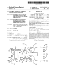
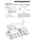
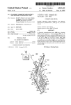
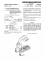
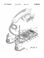
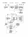
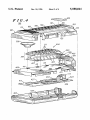
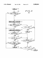
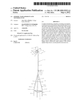
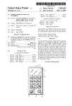
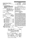
llllllllllllllIllllllllllllllllllllllllllllllllllllllllllllllll|l|l|l|||ll|
US005588041A
United States Patent [19]
[11]
Meyer, Jr. et al.
[45]
[54] CELLULAR SPEAKERPHONE AND
METHOD OF OPERATION THEREOF
.
Operating Guide, 1994.
Motorola, Inc. Cellular Subscriber Group, Cellular Mobile
a
_
Jan. 5, 1995
[56]
37 _% n.7, 3 7 9M2 .0, 3 7 9M3 2
379/58, 59, 420,
379/421, 432, 433; 455/89, 90
4/1988 Potratz et al. .
6/1989 Potratz.
2/1991 Morris
5,018,188
5/1991 Kowalski et al. .
5,224,151
6/1993 Bowen et al.
ABSTRACT
A cellular speakerphone (100) includes a housing (101)
U.S. PATENT DOCUMENTS
4,843,621
4,991,197
Primary Examiner-Dwayne D. Bost
Attorney, Agent, or Firm-Randall S. Vaas
[57]
References Cited
4,741,018
1993.
Cellular Mobile and Carry Phone Accessory, Installation
Manual, 1993.
Motorola, Inc. Pan American Cellular Subsriber Group,
cellular telephone user’s manual, 1993.
[21] Appl. No.: 369,021
[51] Int. Cl.‘5
[52] US. Cl.
[58] Field of Search
and Carry Phone Accessory, NAM-Programming Guide,
Motorola, Inc. Pan American Cellular Subscriber Group,
[73] Asslgnee' Motorola’ Inc" Schaumburg’ 111'
[22] Filed:
5,588,041
Dec. 24, 1996
JRC Canada, Inc., JRC International Inc., Integrated Cellu
lar Telephone Model ICT—8820, User’s Guide, Jun. 1994.
Uniden America Corporation, CP 1700 Cellular Telephone
[75] Inventors: George W. Meyer, 11:, Bu?alo Grove;
Allen Wong, Streamwood; John H.
Spears, McHenry; David L. Bond,
Ho?man Estates; Thomas F. Vondrak
Libertyville, all of I11.
Patent Number :
Date of Patent:
containing a transceiver circuit (203), a processor and
379/58
switching circuit (205), a coupler (209), and a hands-free
user interface (207). The processor and switching circuit
(205) and the hands-free user interface (207) operate the
cellular speakerphone (100) in a default hands-free mode
that is automatically interruptable to permit the cellular
speakerphone (100) to operate in a handset mode when an
OTHER PUBLICATIONS
Northern
Telecom,
Meridian
M5312, User’s
American
5,261,121
Honda
11/1993
Motor
Hashimoto
Co.,Business
Cellular Set
Telephone,
User’s
Guide, 1989.
Manual, Aug. 1994.
optional handset (127) is operably coupled to the cellular
speakerphone (100) via the coupler (209).
15 Claims, 4 Drawing Sheets
US. Patent
Dec. 24, 1996
Sheet 1 of 4
5,588,041
100
103
F .I. G 1
US. Patent
Dec. 24, 1996
Sheet 2 of 4
HANDS-FREE
USER INTERFACE
Tl R A N S c E I v E R
HANDSET
(OPTIONAL )
FIG.3
L101
TRANSCEIVER
CIRCUIT
l l
l I
T l’\
SENSING
DEVICE
EXTERNAL
L
_
_
-
- —-
—
MICROPHONE
(OPTIONAL)
U.S. Patent
Dec. 24, 1996
Sheet 3 of 4
5,588,041
w
g
US. Patent
Dec. 24, 1996
Sheet 4 of 4
5,588,041
501
509
FIG.5
OPTIONAL
HANDSET INqHANGUP-CUP
YES
HANDSET
REMOVED FROM HANGUP-CUP
?
HANDSET
'
ATTACHED TO HANGUP-CUP
?
YES
523
END KEY’) PUSHED
YES
502% STOP )
5,588,041
1
2
CELLULAR SPEAKERPHONE AND
METHOD OF OPERATION THEREOF
FIG. 4 illustrates an exploded front, bottom, and right side
perspective view of the cellular speakerphone according to
FIG. 1; and
FIG. 5 is a ?ow chart illustrating a process of operation of
the cellular speakerphone according to FIGS. 1-4.
BACKGROUND OF THE INVENTION
LII
1. Field of the Invention
This invention relates generally to cellular ‘communica
tion devices and more particularly to cellular speakerphones.
DETAILED DESCRIPTION OF THE
PREFERRED EMBODIMENTS
2. Description of the Related Art
Radio frequency (RF) communication systems, such as
cellular radiotelephone systems, permit a user to communi~
A cellular speakerphone includes a housing containing a
transceiver circuit, a processor coupled to the transceiver
circuit, a hands-free user interface coupled to the transceiver
circuit through the processor, and a coupler for communi
cate from locations within a broad area. Commercially
cating with an optional handset. The hands-free user inter
available cellular radiotelephones include both portable
units that can be carried by the user and mobile units that are 15 face has a microphone and a speaker for operating the
cellular speakerphone in a default hands-free mode. The
permanently mounted to a vehicle. Each of the aforemen
default hands-free mode is automatically interruptable to
tioned cellular radiotelephones has characteristics that make
permit the cellular speakerphone to operate in a secondary
it preferable with respect to the other.
handset mode when an optional handset is operably coupled
Portable cellular radiotelephones, such as MicroTacTM
to the cellular speakerphone.
radiotelephones manufactured and sold by Motorola, Inc.,
FIG. 1 illustrates a cellular speakerphone 100 and
are revered for their compact size. These cellular radiotele
phones include a housing containing a transceiver circuit
optional accessories that may be used therewith. The cellular
and a user interface. The user interface includes a keypad, a
speakerphone 100 is a fully functional cellular subscriber
unit integrated into a single housing 101 and operating in a
default hands-free mode. The hands-free mode permits the
display, a microphone, and a speaker. The portable cellular
radiotelephone is typically powered by a rechargeable bat
tery which is attached to the housing to provide operating
cellular speakerphone 100 to operate in a manner similar to
that of a conventional landline speakerphone; that is, once a
call has been placed or received, the user participates in the
power and detached once depleted for recharging. There
fore, portable cellular telephones must be made to operate at
low power so as to increase the time period between
recharging.
30
(aside from speaking and listening) on the part of the user is
required during the duration of the call. Unlike current
cellular radiotelephones, the cellular speakerphone 100 does
Mobile cellular radiotelephones, such as the Series IV
Cellular Mobile Transceiver radiotelephone manufactured
and sold by Motorola, Inc., are permanently mounted within
a vehicle or transported within a shoulder bag and powered
via the vehicle’s electrical system. As a result, the mobile
cellular radiotelephone may operate at a higher power level
call by directing speech towards, and listening in the direc
tion of, the cellular speakerphone 100. No physical action
not require additional components, such as a handset, an
35
than the portable cellular radiotelephone without detrimen
tally affecting its operating time while bene?ting from an
external microphone, and/or an external speaker, to operate
in hands-free mode. Aside from the added convenience of
use, the compact, integral nature of the cellular speaker
phone 100 minimizes the area required for operation and
installation, improves storage capability, and cost-effec
increased transmission range.
To augment ease of operation, hands-free accessories are
tively simpli?es manufacturing by eliminating the housings,
cables, connectors, and circuitry required for the additional
utilized in conjunction with both portable and mobile cel~
components.
lular radiotelephones. Hands-free accessories are attachable
external apparatuses that allow the portable or mobile cel~
Additionally, unlike low power portable cellular radio
telephones that are concerned with maximizing operation
time between re-charges of their portable batteries, the
cellular speakerphone 100, which is powered by alternative
power sources (see below), is capable of operating at 3 W.
lular radiotelephone to function in a manner similar to a
conventional speaker phone. This provides the user with free
use of his/her hands for other activities, such as taking notes,
during a cellular radiotelephone call. Motorola, Inc. does not
As a result, the cellular speakerphone 100 has a longer range
condone conversing on a cellular radiotelephone while driv
than lower watt units, permitting it to serve as an emergency
ing, an action that is unlawful in some states.
50
device for communicating in more remote regions.
Therefore, there is a need for a cellular radiotelephone
The default hands-free operating mode of the cellular
that bene?ts from the advantages of each of the portable
speakerphone 100 is accomplished by integrating the trans
cellular radiotelephones, mobile cellular radiotelephones,
ceiver circuit with components that are collectively referred
and hands-free accessories.
55
BRIEF DESCRIPTION OF THE DRAWINGS
to as a user interface. In conventional cellular radiotele
phones, the user interface, which may include a microphone,
a display, a keypad, and/or a speaker, is typically contained
in a handset that must be held by a user participating in a
FIG. 1 illustrates a front, top, and left side perspective
view of a cellular speakerphone and accessories that may be
used therewith;
FIG. 2 is a circuit block diagram illustrating a radiotele
phone communication system that may employ a cellular
speakerphone;
call. For example, the user interface of a mobile cellular
radiotelephone permanently mounted in a vehicle comprises
a handset that is coupled to a transceiver module. The
transceiver module is typically located in the trunk of the
vehicle. The user interface of the portable cellular radiotele
phones is typically contained with the transceiver circuit in
FIG. 3 is a circuit schematic in block diagram form 65 a housing that serves as a handset.
The location and arrangement of the components com
illustrating a cellular speakerphone and accessories that may
prising the user interface, or more speci?cally, the hands
be used therewith;
5,588,041
3
4
free user interface, of the cellular speakerphone 100 lend to
its convenient integrated nature. FIG. 1 shows that the
components comprising the hands-free user interface of the
cellular speakerphone 100 are carried on a raised, front outer
surface 103 of the housing 101. The raised, front outer
surface 103 longitudinally interconnects a top outer surface
104 of the cellular speakerphone 100 and a bottom outer
surface of the cellular speakerphone 100.
ninety degrees relative to the ?rst antenna portion 114, such
that a second whip antenna portion 116 thereof extends in an
upward direction perpendicular to the raised, front outer
surface 103 of the cellular speakerphone 100. The second
whip antenna portion 116 may be connected to the ?rst
antenna portion 114 by a hinge so as to be multi-positional.
When the cellular speakerphone 100 is powered-on, the
user places the antenna 115 such that the second whip
A microphone opening 105 is disposed on the raised, front
outer surface 103 below the top outer surface 104. The
antenna portion 116 extends perpendicularly upward with
10
microphone opening 105 permits audible transmit speech
respect to the raised, front outer surface 103 of the cellular
speakerphone 100. When the cellular speakerphone 100 is
provided by the user to reach a microphone 303 (see FIG. 4)
not in use and is to be stored, the user may fold the second
carried on the underside of the raised, front outer surface
103.
whip antenna portion 116 to be juxtaposed with, and extend
A display opening 107 is disposed immediately below the
the area required for storing the cellular speakerphone 100.
The top outer surface 104 of the housing 101 includes an
opening providing access to a ?rst coupler 117. The ?rst
along, a left portion of the housing 101, thereby minimizing
microphone opening 105 on the raised, front outer surface
103. The display opening 107 allows the user to view a
display 305 (see FIG. 4) contained within housing 101. The
coupler 117 mates with a ?rst connector 118 on a cable 119.
Cable 119 includes a second connector 120 that is connected
to a power source, such as a cigarette lighter in a vehicle.
When the second connector 120 is connected to a suitable
power source, and the ?rst connector 118 of the cable 119 is
display 305 visually provides a user with operational infor
mation, such as signal strength and call status. The display
305 may be backlit to permit convenient operation of the
cellular speakerphone 100 at night or in the dark.
A plurality of keypad openings 109 (see FIG. 4) are
disposed on the raised, front outer surface 103 below the
display opening 107. Extending upward from beneath the
25
raised, front outer surface 103 and through the plurality of
keypad openings 109 are a corresponding plurality of actu
atable keys 111. The plurality of actuatable keys 111 are
backlit to permit convenient operation of the cellular speak
erphone 100 at night or in the dark. The plurality of
actuatable keys 111 comprises a portion of a keypad circuit
connected to the ?rst coupler 117, power is supplied to the
cellular speakerphone 100. In FIG. 1, the cable 119 is shown
as a cigarette lighter adapter cable that may be attached to
the ?rst coupler 117 to power the cellular speakerphone 100
from the battery of a vehicle. Power may alternatively be
provided by inserting the second connector 120 in a recep
tacle coupled to a rechargeable battery (not shown) carried
with the cellular speakerphone 100. The ?rst coupler 117
could alternatively be used to couple the cellular speaker
307 that may include conventional telephone keys (0, 1, 2,
phone 100 to a conventional wall outlet via a transformer so
. . . , 9, *, and #) and functional keys (such as recall (RCL),
as to effectively convert the cellular speakerphone 100 into
store (STO), power on/oif (PWR), function (FCN), clear
(CLR), volume up (“), volume down (v), send (SND), and
end (END)) for operating the cellular speakerphone 100.
The keypad circuit 307 is used to initiate and, typically,
a ?xed cellular subscriber unit for use in a remote area where
35
The ?rst coupler 117 also permits coupling of an optional
external microphone 121 while the ?rst connector 118 of the
cable 119 is connected to the ?rst coupler 117. The optional
external microphone 121 includes a microphone connector
120 that mates with the ?rst coupler 117. The optional
external microphone 121 can be placed in close proximity of
the mouth of the user when the cellular speakerphone 100
receive a call. When initiating a call, the user enters the
number to be called by actuating the appropriate keys of the
keypad circuit 307. The user subsequently actuates the key
designated “SND,” which effectively outputs the number to
establish communication. When receiving a call, the user
also actuates the key designated “SND” to take the cellular
must be positioned away from the user.
speakerphone 100 off-hook and, thus, receive the incoming
45
call.
landline communication is not economical.
By locating the plurality of keypad openings 109 below
The housing 101 (see FIG. 1) further includes a pair of
opposing retaining troughs 123 disposed on a right edge 122
and a left edge 124. The pair of opposing retaining troughs
the display opening 107, the user is able to actuate any of the
123 may be used to secure the cellular speakerphone 100 to
plurality of actuatable keys 111 without obstructing the
display opening 107 and the display 305 disposed therebe
neath. When initiating a call, the numerals keyed-in by the
a carrying case (not shown). It is envisioned that the carrying
case include a pair of metal loops (not shown) attached to
user are displayed by the display 305. This arrangement
allows the user the convenience of easy visual veri?cation of
the actuation. This location of the display opening 107
ensures that the user’s view will not become obstructed
while the user enters a number to be called.
55
The right edge 122 (see FIG..4) of the housing 101 is
A speaker opening 113 is disposed in the raised, front
outer surface 103 below the plurality of keypad openings
109. The speaker opening 113 is positioned over a speaker
309. The user receives audible signals produced by the
further contoured to include a second coupler 425 disposed
in a recess 125. The second coupler 425 is available to
couple an optional handset 127 to the cellular speakerphone
100. The second coupler 425 may be implemented using a
RJ-45 connector. It will be recognized that the optional
handset 127 could be coupled using another intermateable
coupler, a wireless radio frequency coupler, or an infrared
speaker 309 carried on the underside of the raised, front
outer surface 103.
'
The top outer surface 104 (see FIG. 1) of the housing 101
includes an antenna 115 extending therefrom. The antenna
115 includes a ?rst antenna portion 114 extending outward
from the top outer surface 104. A joint terminating the ?rst
antenna portion 114, angles the antenna 115' approximately
either side of an elastic strap (not shown) sewn to the inside
of the carrying case. Each of the pair of metal loops hooks
into a corresponding one of the retaining troughs 123 on
housing 101 to secure the cellular speaker phone 100 to the
carrying case for transport therein.
coupler.
65
As previously speci?ed, the cellular speakerphone 100
primarily operates in a hands-free mode so as to maintain
user convenience and a compact integrated nature. However,
5,588,041
5
6
because it is often desirable to utilize a handset for reasons
to the antenna 115. The antenna 115 converts the electrical
of privacy or where there is extremely loud background
noise, the cellular speakerphone 100 is equipped to operate
in a secondary handset mode. When the optional handset
127 is coupled to the cellular speakerphone 100 via the
second coupler, the default hands-free mode is automatically
interrupted as described in greater detail hereinafter.
RF signals into RF signal energy for transmission through
the air to the ?xed transceiver 201.
The cellular speakerphone 100 may further include a
speakerphone coupler 209 coupled to the processor and
switching circuit 205. The cellular speakerphone coupler
209, which collectively comprises the ?rst coupler 117 (see
FIG. 1) and the second coupler 425 (see FIG. 4), permits the
Also shown in FIG. 1 is a hang-up cup 129 that is
optionally associated with the optional handset 127. A top
surface of the optional hang-up cup 129 includes a recessed
portion for accepting a portion of the optional handset 127
(typically an ear piece portion of the handset). The recessed
portion of the optional hang-up cup 129 may be equipped
with protruding retractable members (not shown) that mate
with integral notches (not shown) formed in the portion of
the optional handset 127. A pair of opposing retaining
troughs 131, of which only one is shown, are also disposed
on left and right side portions of the optional hang-up cup
129. The pair of opposing retaining troughs 131, which are
similar to those disposed on the edge portions of the cellular
speakerphone 100, permit attachment of the optional hang
utilization of optional accessories with the cellular speaker
phone 100. One such accessory is the optional handset 127.
When coupled to the cellular speakerphone 100, the proces~
sor and switching circuit 205 may automatically interrupt
the hands-free user interface 207 thereby changing the
operation of the cellular speakerphone 100 from the default
hands-free mode to operate the secondary handset mode.
The secondary handset mode requires the user to utilize the
optional handset 127 to participate in a call.
FIG. 3 is a circuit schematic in block diagram form
20
up cup 129 to a carrying case via metal loops (not shown)
and elastic straps (not shown) in the same manner as
described for the cellular speakerphone 100.
FIG. 2 is a circuit block diagram illustrating a radiotele
phone communication system that may employ the cellular
25
speakerphone 100. A radiotelephone system typically
illustrating the cellular speakerphone 100 and accessories
that may be used therewith. In particular, the processor and
switching circuit 205 and the hands-free user interface 207,
through which the cellular speakerphone 100 operates in a
default hands-free mode and a secondary handset mode, are
further described.
The cellular speakerphone 100 operates in the default
hands-free mode. Aside from initiating and terminating a
call (by pressing the “SND” and “END” keys, respectively),
includes a ?xed transceiver 201, such as a cellular base
the user is required only to listen and speak in the proximity
of the cellular speakerphone 100 for the duration of the call.
In order to provide the default hands~free mode of operation,
the processor and switching circuit 205 functions in con‘
junction with the microphone 303 and the speaker 309 of the
station, that sends out radio frequency (RF) signals to
radiotelephones contained within its geographic coverage
area. One such radiotelephone is the cellular speakerphone
100.
The cellular speakerphone 100 (see FIG. 2) includes the
hands-free user interface 207. The processor and switching
antenna 115 mounted on the housing 101 and a transceiver 35 circuit 205 couples and compresses transmit audio from the
microphone 303 to the transceiver circuit 203 (the “transmit
circuit 203, a processor and switching circuit 205, and a
hands-free user interface 207 disposed primarily within the
housing. It will be recognized that other components of the
cellular speakerphone 100, such as the transceiver circuit
203, may include additional processing circuitry. The pro
cessor and switching circuit 205 operates the hands-free user
interface 207 of the cellular speakerphone 100 in a default
hands-free mode that allows a proximately positioned user
to participate in a cellular radiotelephone call without a
handset.
The antenna 115 is used to transmit and receive RF signals
to and from the ?xed transceiver 201. Upon receiving
signals, the antenna 115 converts the signals into electrical
RF signals and transfers the signals to a receiver portion of
the transceiver circuit 203. The receiver portion of the
transceiver circuit 203 demodulates the received electrical
RF signals, converts the demodulated RF signals into data
signals, and couples the data signals to the processor and
switching circuit 205. The received data signals, which are
now usable by the rest of the cellular speakerphone 100, may
voice pa ”). Likewise, the processor and switching circuit
205 couples and expands the receive audio from the trans
ceiver circuit 203 to the speaker 309 (the “receive voice
path”). In both the transmit and receive voice paths, the
processor and switching circuit 205 digitally samples com
pressed audio signals and controls the voice path gain
switching to produce hands-free communication allowing
the user to communicate by simultaneously talking and
45
The operation of the processor and switching circuit 205
to provide the default hands-free mode is similar to the
operation of the microcomputer and the speakerphone con
trol circuitry described in both U.S. Pat. No. 4,741,018,
entitled “Speakerphone Using Digitally Compressed Audio
to Control Voice Path Gain,” by Portratz et al., granted on
Apr. 26, 1988, assigned to Motorola, Inc., the assignee of the
present invention, and U.S. Pat. No. 4,843,621, entitled
“Speakerphone Using Digitally Compressed Audio to
55
contain voice data that is to be coupled to the hands-free user
interface 207. Upon receipt, the hands-free user interface
207 audibly outputs the voice data in a form that is discern
When the optional handset 127 is coupled via the speak
erphone coupler 209 and a ?rst bus 310, the cellular speak
erphone 100 may be operated in the secondary handset
mode. The optional handset 127 includes a handset coupler
311 coupled between a handset speaker 313, a handset
microphone 315, and a handset sensing device 317. The
speakerphone 100. The hands-free user interface 207 con
verts the user’s speech into voice data that is to be coupled
to a transmitter portion of the transceiver circuit 203 via the
of the transceiver circuit 203 converts and ampli?es the
voice data into electrical RF signals that are further coupled
Detect Acoustic Feedback,” by Portratz, granted on Jun. 27,
1989, and assigned to Motorola, Inc., the assignee of the
present invention, both patents are incorporated herein by
reference thereto.
ible by the proximately positioned user.
The proximately positioned user may respond to the
audible output by speaking in the direction of the cellular
processor and switching circuit 205. The transmitter portion
listening in the proximity of the cellular speakerphone 100.
65
processor and switching circuit 205 automatically interrupts
the default hands-free mode of operation to operate the
cellular speakerphone 100 in the secondary handset mode
5,588,041
7
8
when the handset sensing device 317 outputs an activation
indication signal on conductor 314.
To produce the activation indication signal on conductor
314, the handset sensing device 317 must typically be a
sensor or switch capable of providing a signal upon trigger
ing or actuation. In the preferred embodiment, triggering or
actuation and production of the activation indication signal
the default hands-free mode and the secondary handset
mode of operation. The cellular speakerphone 100 automati
cally responds to the activation indication 314 provided by
the handset sensing device 317. As a result, the user is able
to operate the cellular speakerphone 100 with less distrac
tions and, thus, is able to direct his/her attention to other
actions being performed simultaneously with operation of
on conductor 314 occurs when the user a?irmatively moves
the optional handset 127 for utilization and positioning in
proximity of the ear and mouth. Examples of acceptable
10
sensors and switches include, but are not limited to, a
magnetic reedswitch, an optical sensor, a proximity sensor,
or an orientational sensor. In the preferred embodiment, the
handset sensing device 317 is a magnetic reedswitch.
The activation indication signal on conductor 314 output
ted by the handset sensing device 317 is coupled to the
processor and switching circuit 205 via the handset coupler
311 and the speakerphone coupler 209, whose connection is
represented by a second bus 312, and the ?rst bus 310. In
order to minimize cabling, the optional handset 127 is
coupled to the cellular speakerphone 100 via the second bus
312, which includes a power conductor (not shown), a
ground conductor (not shown), a receive audio conductor
(not shown), and a transmit audio conductor (not shown).
The activation indication signal on conductor 314 outputted
by the handset sensing device 317 is multiplexed on the
receive audio conductor and subsequently coupled to the
processor and switching circuit 205.
the processor and switching circuit 205 when the user
25
The multiplexing apparatus utilized to couple the optional
handset 127 to the cellular speakerphone 100 in the afore
mentioned manner is described in US. Pat. No. 5,018,188,
30
entitled “Microphone-Controller with Multifunction, Single
Conductor,” by Kowalski et al., granted on May 21, 1991,
and assigned to Motorola, Inc., the assignee of the present
invention, incorporated herein by reference thereto.
35
removes the optional handset 127 from the optional hang-up
cup 129. Upon (re-)attachment of the optional handset 127
to the optional hang-up cup 129, the activation indication
signal on conductor 314 is terminated. It will be recognized
that the hang-up cup 129 is optional; that is, the preferable
magnetic reedswitch of the handset sensing device 317 may
be triggered by a magnet sewn in the aforementioned
carrying case associated with the cellular speakerphone 100.
The cellular speakerphone coupler 209 may couple the
optional external microphone 121 to the switching circuit
301 of the hands-free user interface 207. Upon coupling, the
transmit audio is switched from the microphone 303 to the
optional external microphone 121. The processor and
switching circuit 205 includes an impedance sensing circuit
(not shown) coupled to the speakerphone coupler 209. When
Upon reception of the activation indication signal on
conductor 314, the processor and switching circuit 205
automatically switches operation of the cellular speaker
the optional external microphone 121 is connected to the
speakerphone coupler 209, the impedance seen by this
impedance sensing circuit changes. ‘The processor and
switching circuit 205 is responsive to this sensed impedance
phone 100 from the default hands-free mode to the second
ary handset mode. The processor and switching circuit 205
change to connect the external microphone to the transceiver
redirects the receive audio, previously coupled to the
speaker 309 of the hands-free user interface 207 disposed
within the housing 101, to the handset speaker 313. Simi
larly, the processor and switching circuit 205 redirects the
circuit 203 and disconnect the microphone 303, automati
cally.
The communication e?iciency of the default hands-free
mode of operation of the cellular speakerphone 100 is
enhanced by the optional external microphone 121 as the
user is able to position the optional external microphone 121
in closer proximity to his/her mouth than the microphone
transmit audio path, previously coupled through the micro
phone 303 of the hands-free user interface 207 disposed
within the housing 101, to the handset microphone 315.
The audio is redirected in the aforementioned manner for
the duration of a call or until the activation indication signal
on conductor 314 is no longer being received. While in the
the cellular speakerphone 100.
In the preferred embodiment, the optional handset 127 is
associated with hang-up cup 129, which is optionally used
with the optional handset 127. The optional hang-up cup 129
temporarily captures a portion of the optional handset 127;
that is, the optional handset 127 is releasably attachable to
the optional hang-up cup 129. The optional hang-up cup 129
includes a hang-up cup sensing device 319, preferably a
magnet, that operates in conjunction with the preferential
magnetic reedswitch comprising the handset sensing device
317. The hang-up cup sensing device 319 triggers the
magnetic reedswitch of the handset sensing device 317 to
couple the activation indication signal on conductor 314 to
50
303 of the hands-free user interface 207. The optional
external microphone 121 decreases acoustic feedback while
also increasing the signal-to-noise ratio of the transmit audio
(depending upon the proximity of the optional external
microphone 121 to the month). As a result, the optional
external microphone 121 allows for improved hands-free
performance and alternate modes of hands-free operation.
secondary handset mode, the user typically terminates the
call by relinquishing use of the optional handset 127, which
in turn prevents the handset sensing device 317 from out
putting the activation indication signal on conductor 314. 55
The user of the cellular speakerphone 100 also has the ability
Upon coupling, the switching circuit bypasses the micro
to enable prede?ned operating options that allow automatic
phone 303 of the hands-free user interface 207 and couples
switching from the secondary handset mode of operation to
the default hands-free mode of operation during a call. This
the optional external microphone 121 to the processor and
automatic switching is accomplished by relinquishing use of
the optional handset 127, which in tin-n prevents the handset
sensing device 317 from outputting the activation indication
phone 121 electrically operates in manner similar to that of
signal on conductor 314.
Unlike some current cellular speakerphones that require
the user to manually‘ toggle between the hands-free mode
and a handset mode via the actuation of a keypad key, the
cellular speakerphone 100 automatically switches between
switching circuit 205. Although the optional external micro
the microphone 303, the communication e?iciency of the
default hands-free mode of operation of the cellular speak
erphone 100 becomes enhanced as the user is now able to
position the optional external microphone 121 in close
65
proximity to his/her month. As a result, the user does not
have to be concerned with directing his/her speech in the
direction of the cellular speakerphone 100.
5,588,041
10
9
The speaker 309, which is coupled via wires (not shown)
FIG. 4 illustrates an exploded front, bottom, and right side
perspective view 400 of the cellular speakerphone 100. The
to the keypad circuit board 405, is maintained against the
underside of the front housing portion 401, beneath the
antenna 115 has been omitted so as to properly focus on the
internal structure of the cellular speakerphone 100. The
speaker opening 113, by the shielding apparatus 409. A
cellular speakerphone 100 includes a front housing portion
401 and a rear housing portion 403, which collectively form
the housing 101 initially discussed in conjunction with FIG.
1. Interconnecting the front housing portion 401 and the rear
crescent-shaped notch 419 in the keypad 404 allows the
speaker 309 to be closely positioned to the keypad circuit
board 405. The speaker 309 is mounted away from the
housing portion 403 is the top housing portion 104, also
unwanted electrical interference, including acoustic feed
initially discussed with respect to FIG. 1
The front housing portion 401 includes the microphone
microphone 303 so as to achieve separation and prevent
10
back.
Aside from maintaining the position of the aforemen
opening 105, the display opening 107, the plurality of
keypad openings 109, and the speaker opening 113. Posi
tioned components of the hands-free user interface 207, the
shielding apparatus 409 also shields a transceiver circuit
tioned respectively behind the aforementioned openings and
substantially incident to the underside of the front housing
portion 401 are the microphone 303, the display 305, the
keypad circuit 307 comprising a keypad 404 having a
plurality of actuatable keys and a keypad circuit board 405,
board 417 positioned therebeneath from radio frequency
radiation emitted during the operation of the cellular speak~
erphone 100.
The shielding apparatus 409 further includes a connector
opening 421. The connector opening 421 permits direct
coupling of the keypad circuit board 405 to a logic circuit
and the speaker 309 of the hands-free user interface 207 (see
FIG. 3). The microphone 303 and the display 305 are
mounted on the keypad circuit board 405. The keypad 404
resides upon an area of the keypad circuit board 405 adjacent
to the display 305 that contains a plurality of contacts 407
423. The logic circuit 423 is carried on the transceiver circuit
board 417. The logic circuit 423 includes the processor and
switching circuit 205 whose operation was discussed in
relation to FIG. 3.
The ?rst coupler 117 and the second coupler 425 are
nals for use by the display 305 as well as other components 25
mounted on the transceiver circuit board 417. The ?rst
of the cellular speakerphone 100.
for translating the user’s key actuations into electrical sig
coupler 117 and the second coupler 425 are electrically
coupled to the processor and switching circuit 205 of the
logic circuit 423 by conductors (not shown) on the trans
ceiver circuit board 417. The conductors permit coupling of
The keypad 404 (see FIG. 4), and the keypad circuit board
405, on which the microphone 303 and the display 305 are
mounted, are positioned and maintained behind (or in the
case of the keypad 404, through,) their respective openings
on the front housing portion 401 by a plurality of opposing
the activation indication signal on conductor 314 to the
processor and switching circuit 205 and automatic switching
between the default hands-free mode and the secondary
hook members 413, one of which is shown in the cutaway
portion of the front housing portion 401. The plurality of
opposing hook members 413 extend from the underside of
the front housing portion 401 in a substantially orthogonal
handset mode as previously discussed in relation to FIG. 3.
Although the ?rst coupler 117 and the second coupler 425
35
manner. The plurality of opposing hook members 413 are
spaced along a right and a left extremity of the underside of
are shown to attach physical connectors and cabling so as to
minimize cost and complexity, it will be recognized by those
skilled in the art that alternative wireless coupling means
the front housing portion 401. For example, the plurality of
opposing hook members 413 may include six members
could be employed.
spaced so as to be located near the corners of the keypad
circuit board 405 as well as intermediate of the comers along
Positioned beneath the transceiver circuit board 417 is the
rear housing portion 403. The transceiver circuit board 417
the two longitudinal edges of the keypad circuit board 405.
The plurality of opposing hook members 413 extend around
and capture the keypad 404 and the keypad circuit board 405
of the keypad circuit 307. Once captured, the plurality of
actuatable keys 111 comprising the keypad 404 extend
includes a notched opening 427 within which a 3 W power
ampli?er (not shown) of the transceiver circuit 203 may be
positioned. When the transceiver circuit board 417 is placed
45
through the corresponding plurality of keypad openings 109
incident to the rear housing portion 403, the notch 427
containing the 3 W power ampli?er permits direct seating of
the 3 W power ampli?er upon the raised platform 429
while the keypad circuit board 405 and the plurality of
extending from the rear housing portion 403. The rear
contacts 407 disposed thereon are maintained in abutment
housing portion 403, which is preferably comprised of a
metallic material, dissipates, via conduction, the heat gen
erated during the operation of the 3 W power ampli?er of the
against the underside of the keypad 404. In addition, the
microphone 303 and the display 305 are positioned and
maintained under their respective openings. A transparent
display lens cover 402 is ?ttable to the display opening 107
to protect the display 305 disposed therebeneath.
The plurality of opposing hook members 413 are pre
50
transceiver circuit 203.
FIG. 5 is a ?ow chart illustrating a process of operation
500 of a cellular speakerphone. The operation of the cellular
55 speakerphone 100 (see FIGS. 2 and 3) is directed via a set
vented from spreading apart and releasing the keypad 404
and the keypad circuit board 405 by a shielding apparatus
of predetermined instructions performed by the processor
409. The shielding apparatus 409 may be of any suitable
tions are contained within a memory (not shown) associated
construction, such as a stamped metal member. A front
surface of the shield apparatus 409 includes a plurality of
and switching circuit 205. The set of predetermined instruc
integral loops 411 extending therefrom. Each of the plurality
with the processor and switching circuit 205.
The process of operation 500 begins at decision block 501
when a call is initiated. A call is initiated by the user making
of opposing hook members 413 abuts against a correspond
a call from the cellular speakerphone 100 or receiving an
_ ing one of the plurality of integral loops 411. When the
incoming call at the cellular speakerphone 100. At decision
block 501, the processor and switching circuit 205 deter
mines whether the user has preselected an option that
facilitates operation of the cellular speakerphone 100. Such
options may include automatic answer, which directs the
plurality of actuatable keys comprising the keypad 404 are
actuated, the plurality of integral loops 411 maintain the
substantially orthogonal orientation of the plurality of
opposing hook members 413.
65
5,588,041
11
12
cellular speakerphone 100 to automatically answer an
incoming call in a default hands-free mode after alerting the
user of the incoming call.
Upon initiation of a call, the processor and switching
circuit 205 determines whether the cellular speakerphone
100 is to operate in the default hands-free mode of operation
or the secondary handset mode of operation. The processor
and switching circuit 205 determines if the optional handset
127 has been removed from the optional hang-up cup 129,
i.e., the activation indication signal on conductor 314 has
been sent, at decision block 509. Ifthe optional handset 127
has not been removed from the optional hang-up cup 129,
the processor and switching circuit 205 proceeds to decision
block 511 to operate the cellular speakerphone 100 in the
default hands-free mode. If the optional handset 127 has
been removed from the optional hang-up cup 129, the
processor and switching circuit 205 performs decision block
513 to operate the cellular speakerphone 100 in the second
ary handset mode of operation.
As indicated above, the cellular speakerphone 100 oper
ates in the default hands-free mode of operation beginning
If the processor and switching circuit 205 determines that
the automatic hands-free is not enabled, in decision block
519, and the microphone is not muted, in decision block 525,
the processor and switching circuit 205 proceeds to decision
block 527. In decision block 527, the processor and switch
ing circuit 205 determines whether the call has been termi
nated, either by actuation of the “END” key or by placing the -
optional handset 127 in the optional hang-up cup 129. Upon
10
In summary, the cellular speakerphone includes a trans
ceiver circuit, a processor, and a hands-free user interface
contained within a single housing. The cellular speaker
phone operates in a default hands-free mode via the hands
free user interface. Unlike current cellular radiotelephones,
the cellular speakerphone 100 does not require additional
20
optional hang-up cup 129 while the cellular speakerphone
storage capability, and cost-effectively simpli?es manufac
turing by eliminating housings, cables, connectors, and
circuitry. The cellular speakerphone is further capable of
coupling to an optional handset. When the optional handset
is coupled, the default hands-free mode is automatically
interruptable to permit the cellular speakerphone to operate
30
this description is by example only and that numerous
ary handset mode of operation as indicated at block 513.
35
1. A portable cellular speakerphone comprising:
a housing;
a transceiver circuit disposed within said housing;
a processor and switching circuit disposed in said housing
and coupled to said transceiver circuit for controlling
said transceiver circuit;
45
a coupler carried on said housing and coupled to said
processor and switching circuit for communicating
mode of operation, at block 513.
If the automatic hands-free mode is not enabled, as 50
determined at decision block 519, the processor and switch
ing circuit 205 proceeds to decision block 525. In decision
block 525, the processor and switching circuit 205 deter
mines if the microphone has been muted. In a preferred
If the microphone is muted and the optional handset 127 is
determined to have been in the optional hang-up cup 129 at
decision block 521, the processor and switching circuit 205
proceeds to block 511, switching the operation of the cellular
speakerphone 100 from the secondary handset mode of
operation to the default hands-free mode of operation. If the
microphone is muted and the handset remains out of the
optional hang-up cup 129, the call continues in the second
ary handset mode of operation at block 513 until the “END”
key is determined to have been actuated at decision block
523.
.
We claim:
switching circuit 205 continues in the secondary handset
embodiment, the microphone may be muted by actuating the
“FCN" key followed by the “6” key on keypad circuit 307.
changes and modi?cations can be made by those skilled in
the art without departing from the true spirit and scope of the
invention.
optional hang-up cup 129, the processor and switching
circuit 205 determines if the “END” key is actuated at
decision block 523. If it is actuated, the process of operation
500 stops at block 502. If it was determined at decision block
523 that the “END” key was not actuated, the processor and
in a secondary handset mode.
Although the invention has been described and illustrated
in the above description and drawings, it is understood that
100 is in the default hands-free mode of operation, the
processor and switching circuit 205 changes to the second
In the secondary handset mode of operation, the processor
and switching circuit 205 determines if automatic hands-free
mode has been previously enabled by the user at decision
block 519. If the automatic hands-free mode is actuated, the
processor and switching circuit 205 determines if the
optional handset 127 is in the optional hang-up cup 129, as
indicated at decision block 521. If automatic hands-free
mode is enabled and the optional handset 127 is not in the
components, such as a handset, an external microphone,
and/or an external speaker, to operate in hands-free mode.
Aside from the added convenience of use, the compact,
integral nature of the cellular speakerphone 100 minimizes
the area required for operation and installation, improves
at block 511. It remains in this mode of operation until the
optional handset is removed from the optional hang-up cup
129, as determined at decision block 515, or the call is
terminated by the user actuating the “END” key, as indicated
at decision block 517. Upon termination, the process of
operation 500 stops at block 502.
If it is determined in decision block 509 or decision block
515, that the optional handset 127 is removed from the
termination, the process of operation 500 stops at block 502.
If it is determined in decision block 527 that the optional
handset 127 remains out of the optional hang-up cup 129 and
the “END” key has not been actuated, the call continues in
the secondary handset mode of operation, at block 513.
with an optional handset; and
a hands-free user interface disposed within said housing
and coupled to said processor and switching circuit,
said hands-free user interface including a ?rst micro
phone and a ?rst speaker for operating the portable
cellular speakerphone in a default hands-free mode,
said processor and switching circuit coupling said
hands-free user interface to said transceiver circuit in a
55
default hands-free mode, and said processor and
switching circuit responsive to detecting an activation
indication signal from an optional handset coupled to
said coupler to automatically interrupt the default
hands-free mode to permit the portable cellular speak
erphone to operate in a handset mode.
2. The portable cellular speakerphone of claim 1 further
including the optional handset including a second micro
phone and a second speaker, and wherein said optional
handset includes a ?rst device generating the activation
65
indication signal.
3. The portable cellular speakerphone of claim 2 further
including a hang-up cup for releasably coupling to said
5,588,041
13
14
optional handset, said hang-up cup including a second
board from cellular frequency radiation emitted during
operation of the cellular speakerphone, said shielding appa
ratus further containing a plurality of integral loops extend
ing from a surface thereof, each of said plurality of integral
loops abutting a corresponding one of a plurality of integral
hook members that extend both beneath said housing and
around said keypad and said keypad circuit board.
9. A portable cellular speakerphone having an‘ integral
speaker and an integral microphone comprising:
device for operation with said ?rst device.
4. The portable cellular speakerphone of claim 1 wherein
said default hands-free mode is further automatically inter
ruptable to disconnect said ?rst microphone when an
optional microphone is releasably coupled to said coupler to
permit the portable cellular speakerphone to operate in an
enhanced hands-free mode via said optional microphone and
said ?rst speaker.
5. The portable cellular speakerphone of claim 4 wherein
means for operating in a default hands-free mode during
said processor and switching circuit senses an impedance of
a call;
said coupler, said processor and switching circuit responsive
means for detecting an activation indication signal from
to a ?rst sensed impedance to disconnect said ?rst micro~
phone from said transceiver and connect the optional micro
phone to said transceiver, and responsive to a second sensed
impedance and detection of the activation indication signal
15
to disconnect said ?rst microphone and said ?rst speaker
from said transceiver and connect the optional handset to
mode to the handset mode.
6. The portable cellular speakerphone of claim 1 wherein
said housing further including an outer surface, the outer
10. A cellular speakerphone comprising:
a housing having a plurality of housing openings;
surface including:
a transceiver circuit board disposed within said housing;
a transceiver circuit disposed on said transceiver circuit
25
keypad;
a shielding apparatus disposed between said keypad cir
display remains unobstructed during actuation of said
cuit board and said transceiver circuit board for shield
ing said transceiver circuit board from cellular fre
plurality of actuatable keys.
7. A cellular speakerphone comprising:
35
having a plurality of keys extending through a corre
sponding plurality of openings in said housing;
keypad;
a shielding apparatus disposed beneath said keypad circuit
board for maintaining said keypad and said keypad
board in contact;
a processor and switching circuit disposed within said
housing and coupled to said transceiver circuit for
circuit board in contact;
a processor and switching circuit coupled to said trans
ceiver circuit for controlling said transceiver circuit;
a coupler coupled to said processor and switching circuit
for communicating with an optional handset; and
a hands-free user interface disposed within said housing
and coupled to said processor and switching circuit,
45
50
said hands-free user interface including a ?rst micro
phone and a ?rst speaker for operating the cellular
speakerphone in a default hands-free mode, said pro
cessor and switching circuit coupling said hands-free
controlling said transceiver circuit;
a coupler at least partially disposed within said housing
for communicating with an optional handset; and
a hands-free user interface disposed within said housing
and coupling said transceiver circuit through said pro
cessor and switching circuit and having a ?rst micro
phone and a ?rst speaker for operating the cellular
speakerphone in a default hands-free mode, said default
hands-free mode being automatically interruptable to
55
user interface to said transceiver circuit in a default
permit the cellular speakerphone to operate in a handset
mode when an optional handset having a second micro
phone and a second speaker is operably coupled
hands-free mode, and said processor and switching
circuit detecting that an optional handset is coupled to
said coupler to automatically interrupt the default
hands-free mode to permit the cellular speakerphone to
thereto.
11. A method of operating a portable cellular speaker
phone having an integral speaker and an integral micro»
phone comprising the steps of:
operate in a handset mode when the optional handset is
(a) operating in a default hands-free mode during a call;
(b) detecting an activation indication signal from an
operably coupled to said coupler.
8. The cellular speakerphone of claim 7 further including
a transceiver circuit board upon which said transceiver
circuit is disposed wherein said shielding apparatus is inter
posed between said keypad circuit board and said trans
ceiver circuit board for shielding said transceiver circuit
quency radiation emitted during operation of the
cellular speakerphone, said shielding apparatus further
containing a plurality of integral loops extending from
a surface thereof, each of said plurality of integral loops
abutting a corresponding one of a plurality of integral
hook members extending beneath said housing and
around both said keypad and said keypad circuit board
for maintaining said keypad and said keypad circuit
a keypad circuit board positioned directly beneath said
a transceiver circuit disposed within said housing;
board;
a keypad positioned beneath and carried on said housing
having a plurality of keys extending through at least
some of said plurality of housing openings;
a keypad circuit board positioned directly beneath said
opening; and
a plurality of actuatable keys extending through said
plurality of openings, said plurality of actuatable keys
being positioned below said display such that said
a housing;
a keypad positioned beneath and carried on said housing
cate a handset mode of operation; and
means, responsive to said means for detecting, for auto
matically switching the call from the default hands-free
said transceiver.
a ?rst opening for said ?rst microphone;
a second opening for said ?rst speaker;
a third opening, a display positioned at said third opening;
a plurality of openings disposed adjacently to said third
an optional handset coupled to the portable cellular
speakerphone, the optional handset having an indicator
for generating the activation indication signal to indi
65
optional handset coupled to the portable cellular speak
erphone, the optional handset having an indicator for
generating the activation indication signal to indicate a
handset mode of operation; and
5,588,041
15
16
(c) automatically switching, responsive to detecting, the
14. A method of operating a portable cellular speaker
phone according to claim 13 wherein said step (d) further
call from the default hands-free mode to a handset
mode.
12. A method of operating a portable cellular speaker
phone according to claim 11 wherein said step (0) further
comprises the substep of:
(cl) detecting removal of the optional handset from an
optional hang-up cup, the optional hang-up cup having
a device for operation with the indicator.
13. A method of operating a portable cellular speaker
phone according to claim 11 further comprising the step of:
((1) switching the call from the handset mode to the default
hands-free mode.
comprises the substep of:
(d1) attaching the optional handset to an optional hang-up
5
cup.
15. A method of operating a portable cellular speaker
phone according to claim 13 wherein said step (d) further
comprises the substeps of:
(d1) muting the integral microphone of the portable
cellular speakerphone; and
(d2) attaching the optional handset to an optional hang-up
cup.


![T] .1](http://vs1.manualzilla.com/store/data/005831826_1-5c5b79be6c7f2f902c022f1ff12b7474-150x150.png)