1
www.eionwireless.com
LibraPlus 5845
PN: 5724-0003
Document version: 1.73
Released on February 10 2010
This page is intentionally left blank
Table of Contents
1. Important Information ................................................................................................. 1
1.1. Safety Warnings ............................................................................................... 1
1.1.1. Safety Considerations ............................................................................. 1
1.1.2. Warning Symbols Used in this Manual ....................................................... 1
1.2. Notices and Contacts ........................................................................................ 1
1.2.1. Copyright Notice ................................................................................... 1
1.2.2. Regulatory Notice .................................................................................. 2
1.2.3. Other Notices ........................................................................................ 3
1.2.4. Warranty and Repair ............................................................................... 3
1.2.5. Customer Support Contacts ..................................................................... 3
1.2.6. Distributor Technical Support ................................................................... 3
1.2.7. Contact Technical Support ....................................................................... 3
2. Description ................................................................................................................ 4
2.1. LibraPlus Series Products .................................................................................. 4
2.1.1. Overview ............................................................................................. 4
2.1.2. Proprietary Protocol ............................................................................... 4
2.1.3. About OFDM ........................................................................................ 4
2.1.4. About Point-to-Multi-Point (P-MP) Systems ............................................... 5
2.1.4.1. Point to Multipoint based on CSMA ............................................... 6
2.1.4.2. LibraPlus 5845 Adaptive Polling Protocol ........................................ 7
2.1.4.3. Access Point (AP) Equipment ........................................................ 7
2.1.4.4. Customer Premise Equipment (CPE) ............................................... 7
2.1.4.5. Long Range Customer Premise Equipment (LCPE) ........................... 8
2.1.4.6. Radio Operation Background ......................................................... 8
2.1.4.7. Quality of Service (QoS) .............................................................. 9
2.1.5. About Point-to-Point (P-P) Systems ........................................................... 9
2.1.5.1. DenFlow Proprietary Protocol ...................................................... 10
2.1.5.2. Rapid Deployment (RD) Equipment .............................................. 10
2.1.5.3. Extened Range (ER) Equipment ................................................... 10
2.1.6. Hardware ........................................................................................... 10
2.1.7. Specifications ...................................................................................... 15
2.2. System Applications ........................................................................................ 20
2.2.1. Making a Simple Wireless Bridge ........................................................... 20
2.2.2. Creating a Simple Wireless Network ........................................................ 20
3. Field Installation ....................................................................................................... 22
3.1. Introduction ................................................................................................... 22
3.2. LibraPlus Point-to-Point Quick Setup ................................................................. 22
3.2.1. Slave (RD or ER) Unit .......................................................................... 24
3.2.2. Master (RD or ER) Unit ........................................................................ 25
3.3. LibraPlus Point-to-Multipoint Quick Setup .......................................................... 24
3.3.1. CPE Unit ............................................................................................ 24
3.3.2. AP Unit .............................................................................................. 25
3.4. LibraPlus Field Installation ............................................................................... 26
3.4.1. Site Preparation ................................................................................... 26
3.4.2. Tools and equipment ............................................................................. 26
3.4.3. LibraPlus Package Checklist .................................................................. 27
3.4.4. LibraPlus installation procedure .............................................................. 28
3.4.4.1. Mounting the LibraPlus Unit ....................................................... 28
3.4.4.2. Connecting the LibraPlus ............................................................ 29
3.4.4.3. SSH Connection ........................................................................ 29
3.4.4.4. Serial Connection ...................................................................... 29
3.4.4.5. Antenna Alignment .................................................................... 30
3.4.4.6. Configuration and Link Test ........................................................ 31
3.4.4.7. Test network connectivity ............................................................ 31
3.4.4.8. Secure the Installation ................................................................ 32
iii
LibraPlus User Manual
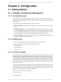
4. Configuration ........................................................................................................... 33
4.1. Getting Started ............................................................................................... 33
4.1.1. LibraPlus Configuration Management ...................................................... 33
4.1.1.1. Configuration types .................................................................... 33
4.1.1.2. Default Login ........................................................................... 33
4.1.1.3. CLI Auto Complete .................................................................... 33
4.1.1.4. CLI Help ................................................................................. 34
4.1.1.5. Viewing Configuration ............................................................... 34
4.1.1.6. Copying Configuration .............................................................. 34
4.1.1.7. Configuration File Format .......................................................... 35
4.1.1.8. Command Summary .................................................................. 36
4.1.2. Running a TFTP server ......................................................................... 37
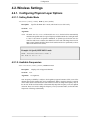
4.2. Wireless Settings ............................................................................................ 38
4.2.1. Configuring Physical Layer Options ....................................................... 38
4.2.1.1. Setting Radio Mode ................................................................... 38
4.2.1.2. Available Frequencies ................................................................. 38
4.2.1.3. Setting a Specific Carrirer Frequency ............................................ 39
4.2.1.4. Setting Data Transmission Rate .................................................... 40
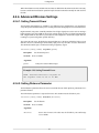
4.2.2. Configuring SSID ................................................................................ 40
4.2.3. Configuring multiple SSID .................................................................... 40
4.2.4. Advanced Wireless Settings .................................................................... 42
4.2.4.1. Setting Transmit Power ............................................................... 42
4.2.4.2. Setting Distance Parameter .......................................................... 42
4.2.4.3. Setting Dynamic Frequency Selection (DFS) .................................. 43
4.2.4.4. Setting Automatic Transmit Power Control (ATPC) .......................... 43
4.2.5. Wireless Security Settings ...................................................................... 44
4.2.5.1. Wireless Security Overview ......................................................... 44
4.2.5.2. Configuring Wired Equivalent Privacy (WEP) ................................ 46
4.2.5.3. Setting Wi-Fi Protected Access ..................................................... 49
4.2.5.4. Certificate Management ............................................................. 58
4.2.5.5. MAC Address Based Filtering ...................................................... 59
4.2.5.6. Client Bridging ......................................................................... 61
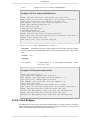
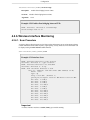
4.2.6. Wireless Interface Monitoring ................................................................ 62
4.2.6.1. Scan Procedure ........................................................................ 62
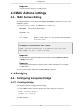
4.3. MAC Address Settings .................................................................................... 63
4.3.1. MAC Address Setting .......................................................................... 63
4.4. Bridging ....................................................................................................... 63
4.4.1. Configuring transparent bridge ............................................................... 63
4.4.1.1. Creating a bridge ....................................................................... 63
4.4.1.2. Wireless interface configuration ................................................... 64
4.4.1.3. Deleting a bridge ....................................................................... 65
4.4.1.4. Viewing Bridge Status ................................................................ 65
4.4.1.5. Bridge Command Summary ........................................................ 66
4.5. VLAN .......................................................................................................... 67
4.5.1. Overview ............................................................................................ 67
4.5.1.1. Point-to-Point VLAN System ....................................................... 68
4.5.1.2. Point-to-Multipoint VLAN System ............................................... 68
4.5.2. Command Summary ............................................................................. 69
4.6. IP Settings ..................................................................................................... 69
4.6.1. Interface Parameters ............................................................................. 69
4.6.1.1. IP address ................................................................................ 69
4.6.1.2. Dynamic (DHCP) IP address ....................................................... 71
4.6.1.3. IP broadcast address ................................................................... 72
4.6.1.4. MTU size ................................................................................. 72
4.6.2. DNS .................................................................................................. 72
4.6.3. Domain Name ..................................................................................... 73
4.6.4. Host Name .......................................................................................... 74
4.6.5. ARP Table .......................................................................................... 75
iv
LibraPlus User Manual
4.6.6. Static Routing and Default Gateway ........................................................ 76
4.6.7. Static Hosts ......................................................................................... 78
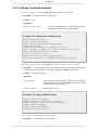
4.7. DHCP Server ................................................................................................. 79
4.7.1. DHCP Server ..................................................................................... 79
4.7.2. Command summary ............................................................................. 81
4.8. Firewall and NAT ........................................................................................... 84
4.8.1. Access Control Lists ............................................................................ 84
4.8.1.1. Source and Destination Specifiers ................................................ 85
4.8.1.2. Access list binding ..................................................................... 85
4.8.1.3. Viewing ACL settings ................................................................. 86
4.8.2. Network Address Translation ................................................................. 87
4.8.2.1. Examples ................................................................................. 88
4.8.2.2. Viewing NAT lists ...................................................................... 88
4.9. PPP .............................................................................................................. 88
4.9.1. Overview ............................................................................................ 88
4.9.2. Command Summary ............................................................................. 90
4.10. RADIUS Profiles .......................................................................................... 94
4.10.1. RADIUS Profiles ............................................................................... 94
4.10.2. Command summary ............................................................................ 95
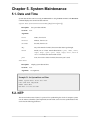
5. System Maintenance .................................................................................................. 97
5.1. Date and Time ............................................................................................... 97
5.2. NTP ............................................................................................................. 97
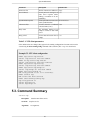
5.3. Command Summary ....................................................................................... 98
5.4. System Update ............................................................................................. 101
5.4.1. Overview .......................................................................................... 101
5.4.2. Command Summary ........................................................................... 101
5.5. Reboot ........................................................................................................ 102
5.6. Password Reset ............................................................................................ 103
5.7. SNMP ........................................................................................................ 104
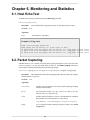
6. Monitoring and Statistics .......................................................................................... 106
6.1. Host Echo Test ............................................................................................. 106
6.2. Packet Capturing .......................................................................................... 106
6.3. Route Tracing .............................................................................................. 107
6.4. System Logging ........................................................................................... 107
6.5. General System Info ...................................................................................... 108
7. Troubleshooting ...................................................................................................... 110
7.1. Troublshooting the LibraPlus .......................................................................... 110
7.1.1. Preventative maintenance ..................................................................... 110
7.1.2. Troubleshooting Areas ......................................................................... 110
7.1.3. Troubleshooting Chart ......................................................................... 112
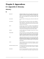
8. Appendices ............................................................................................................ 116
8.1. Appendix A: Glossary .................................................................................... 116
8.2. LibraPlus 5845 Integrated Antenna Specifications ............................................... 124
v
List of Figures
2.1. Orthogonal Arrangement of OFDM Subchannels ............................................................ 6
2.2. LibraPlus P-MP System Components ........................................................................... 6
2.3. Time Division Duplexing Channels .............................................................................. 9
2.4. Time Division Multiplexing/Time Division Multiple Access (TDM/TDMA) ........................ 9
2.5. LibraPlus Connection Panel ...................................................................................... 11
2.6. CAT-5 Weatherproofing Kit ...................................................................................... 11
2.7. Round Cable Bead .................................................................................................. 11
2.8. LibraPlus AP, ER and LCPE Front Panel RF Connector ................................................. 12
2.9. Ethernet Power Inserter ............................................................................................ 12
2.10. Mounting ............................................................................................................ 13
2.11. Large Pipe Diameter Mounting Configuration ............................................................ 13
2.12. Small Pipe Diameter Mounting Configuration ............................................................ 14
2.13. Wall Mounting Configuration .................................................................................. 14
2.14. Point-to-Point Wireless Bridge ................................................................................ 28
2.15. Point-to-Multipoint Wireless Network ....................................................................... 28
3.1. Installation Process ................................................................................................. 22
3.2. LibraPlus Assembly Diagram .................................................................................... 28
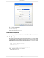
3.3. COM 1 Propertries .................................................................................................. 30
4.1. Multipoint VLAN Configuration ............................................................................... 68
8.1. Azimuth Radiation Pattern Midband Freq. 5.45 GHz ................................................... 128
8.2. Azimuth Radiation Pattern Midband Freq. 5.35 GHz ................................................... 128
vi
List of Tables
2.1. LibraPlus 5845 Radio Specifications .......................................................................... 16
2.2. LibraPlus 5845 Network Support Specifications ......................................................... 113
2.3. LibraPlus 5845 Wireless Networking Specifications .................................................... 113
2.4. LibraPlus 5845 Security Specifications ..................................................................... 113
2.5. LibraPlus 5845 Management Specifications ............................................................... 113
2.6. LibraPlus 5845 Physical, Electrical and Environmental Specifications ............................. 113
4.1. WPA Configuration Table ........................................................................................ 51
4.2. Source and Destination Specifiers .............................................................................. 85
5.1. NTP client parameters ............................................................................................. 98
7.1. Troubleshooting Chart ........................................................................................... 113
8.1. Integrated Antenna Specifications - Electrical ............................................................. 125
8.2. Integrated Antenna Specifications - Mechanical .......................................................... 126
8.3. Integrated Antenna Specifications - Envorinmental ...................................................... 127
vii
List of Examples
4.1. Viewing configuration ............................................................................................. 34
4.2. Viewing configuration part ....................................................................................... 34
4.3. Configuration backup and restore .............................................................................. 35
4.4. Specify IEEE 802.11 mode ....................................................................................... 38
4.5. List supported channels ........................................................................................... 39
4.6. Set Carrier Frequency .............................................................................................. 39
4.7. Set data rate ........................................................................................................... 40
4.8. Specify Service Set ................................................................................................. 40
4.9. Configuring Multiple SSID ...................................................................................... 41
4.10. Setting Transmit Power .......................................................................................... 42
4.11. Setting the Distance Parameter ................................................................................ 43
4.12. Enable DFS ......................................................................................................... 44
4.13. Enable DFS ......................................................................................................... 44
4.14. Static WEP access point ......................................................................................... 47
4.15. Static WEP EAP-MD5 station (CPE) ........................................................................ 47
4.16. Dynamic WEP TTLS station (CPE) .......................................................................... 48
4.17. Set/Delete WEP key by index .................................................................................. 49
4.18. Access point WPA+WPA2 PSK example ................................................................... 49
4.19. Access point WPA+WPA2 EAP example ................................................................... 50
4.20. WPA2 PSK station (CPE) ....................................................................................... 51
4.21. WPA PEAP station (CPE) ....................................................................................... 52
4.22. WPA2 EAP-TLS station (CPE) ................................................................................ 52
4.23. WPA2 EAP-TTLS+MD5 station (CPE) ..................................................................... 53
4.24. Download a PEM file from a TFTP server ................................................................. 59
4.25. Show Certificate Contents ...................................................................................... 59
4.26. Add/Delete MAC address to list ............................................................................... 60
4.27. Add/Delete MAC address using short command form .................................................. 60
4.28. MAC Address White/Black list ................................................................................ 61
4.29. Disconnect remote station ....................................................................................... 61
4.30. Enable client bridging between CPEs ........................................................................ 62
4.31. Interface Scan. ..................................................................................................... 62
4.32. Set an interface MAC Address ................................................................................. 63
4.33. Enable WDS Mode ............................................................................................... 65
4.34. Deleting a Bridge .................................................................................................. 65
4.35. Add Interface to Bridge Group ................................................................................. 66
4.36. Assign a bridge IP legatee ....................................................................................... 66
4.37. View Members of Bridge Group .............................................................................. 67
4.38. View MAC Address of a Bridge Interface .................................................................. 67
4.39. Bridging a wireless VLAN to an untagged wired link ................................................... 69
4.40. Setting an IP address ............................................................................................. 70
4.41. Adding secondary IP addresses ................................................................................ 70
4.42. Deleting an IP address ........................................................................................... 71
4.43. Deleting all IP addresses ........................................................................................ 71
4.44. Add/Remove DNS Server ....................................................................................... 73
4.45. View the name server list contents ............................................................................ 73
4.46. Set/Clear local domain name ................................................................................... 74
4.47. View local domain name setting ............................................................................... 74
4.48. Set/Clear local host name ....................................................................................... 74
4.49. View local host name setting ................................................................................... 75
4.50. Creating and Deleting an ARP Record ...................................................................... 75
4.51. Create ARP Table ................................................................................................. 76
4.52. View ARP Cache .................................................................................................. 76
4.53. Show ARP Cache Size ........................................................................................... 76
4.54. Add static route .................................................................................................... 77
4.55. Delete static route ................................................................................................. 77
viii
LibraPlus User Manual
4.56. Show static route .................................................................................................. 78
4.57. Add/Delete host table entry ..................................................................................... 78
4.58. View static host table ............................................................................................. 79
4.59. Network pool configuration .................................................................................... 80
4.60. Host pool configuration .......................................................................................... 81
4.61. Set and Disable Pool Type ...................................................................................... 81
4.62. Set pool type to host .............................................................................................. 82
4.63. Add DHCP client address range to a network pool ....................................................... 82
4.64. Set DHCP Lease Time ........................................................................................... 83
4.65. Set default gateway IP addresses for DHCP clients ...................................................... 83
4.66. Set DNS server IP addresses for DHCP clients ........................................................... 84
4.67. Set a MAC address for a host pool ............................................................................ 84
4.68. Deny everything ................................................................................................... 85
4.69. Permit TCP .......................................................................................................... 86
4.70. Permit TCP for a subnetwork .................................................................................. 86
4.71. Open various TCP and UDP ports ............................................................................ 86
4.72. Viewing ACL ....................................................................................................... 87
4.73. Simple NAT ......................................................................................................... 88
4.74. Masquerade ......................................................................................................... 88
4.75. Port forwarding .................................................................................................... 88
4.76. PPTP interface ..................................................................................................... 89
4.77. PPPoE interface .................................................................................................... 90
4.78. Set PPP interface name .......................................................................................... 91
4.79. Set PPP authentication identity ................................................................................ 91
4.80. Set/Clear PPP authentication password ...................................................................... 92
4.81. Enable/Disable PPP autoconnection ......................................................................... 92
4.82. Enable/Disable MPPE encryption ............................................................................ 92
4.83. Enable/Disable PAP authentication ........................................................................... 93
4.84. Enable/Disable CHAP authentication ........................................................................ 93
4.85. Enable/Disable MSCHAP authentication ................................................................... 93
4.86. Enable/Disable MSCHAPv2 authentication ............................................................... 94
4.87. Enable/Disable setting defualt gateway ..................................................................... 94
4.88. Accept/Ignore remote DNS ..................................................................................... 94
4.89. RADUIS profile settings ........................................................................................ 96
5.1. Set System Date and Time ........................................................................................ 97
5.2. NTP client configuration .......................................................................................... 98
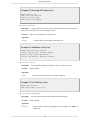
5.3. Start/Stop NTP client service .................................................................................... 99
5.4. Add/Remove NTP server .......................................................................................... 99
5.5. Set NTP Retry count ............................................................................................... 99
5.6. Set NTP retry period .............................................................................................. 100
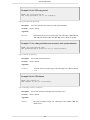
5.7. Set a time period between successive clock synchronizations ......................................... 100
5.8. Set NTP timeout ................................................................................................... 100
5.9. Set NTP offset ...................................................................................................... 101
5.10. Firmware update ................................................................................................. 101
5.11. Download firmware image .................................................................................... 102
5.12. System update .................................................................................................... 102
5.13. Reboot .............................................................................................................. 103
5.14. Show reboot timer ............................................................................................... 103
5.15. Change Password ................................................................................................ 103
5.16. Set SNMP Community ......................................................................................... 104
5.17. Set SNMP Contact .............................................................................................. 104
5.18. Set SNMP Location ............................................................................................. 104
5.19. Set SNMP Allow ................................................................................................. 105
5.20. Enable/Disable SNMP Agent ................................................................................. 105
6.1. Ping a host ........................................................................................................... 106
6.2. Capture TCP packets ............................................................................................. 107
6.3. Traceroute. .......................................................................................................... 107
6.4. Start syslog service ................................................................................................ 108
ix
LibraPlus User Manual
6.5. Show CPU load .................................................................................................... 108
6.6. Show uptime ........................................................................................................ 108
6.7. Show interfaces .................................................................................................... 109
x
Chapter 1. Important Information
1.1. Safety Warnings
1.1.1. Safety Considerations
This document must be reviewed for familiarization with the product, instructions, and safety symbols
before operation.
Verify that local safety regulations are adhered to during installation with regard to grounding and
lightning protection.
Verify that the correct AC power source is available for the Power Inserter.
Disconnect the product from operating power before cleaning.
1.1.2. Warning Symbols Used in this Manual
Warning
Injury or death may result from failure to heed a WARNING. Do not proceed beyond a
WARNING until the indicated conditions are fully understood and met.
Caution
Damage to equipment may result from failure to heed a caution. Do not proceed beyond a
CAUTION until the indicated conditions are understood and met.
Important
Indicates critical information to be aware of which may affect the completion of a task or
successful operation of equipment.
Warning
All antennas must be installed by a knowledgeable and professional installer.
Caution
An antenna must be connected to the AP, LCPE or ER unit before powering up the equipment.
Powering up equipment without an antenna connected can permanently damage the unit or
the RF transmission cable
Caution
Change the passwords and community names as soon as possible. Default community names
and passwords given in this book are provided to all customers and are not secure.
1.2. Notices and Contacts
1.2.1. Copyright Notice
Copyright © July 2009 EION, Inc.
All rights reserved.
1
Important Information
This guide, the application and hardware described herein are furnished under license and are subject
to a confidentiality agreement. The software and hardware can be used only in accordance with the
terms and conditions of this agreement.
No part of this guide may be reproduced or transmitted in any form or by any means – electronic,
mechanical, or otherwise, including photocopying and recording – without the express written permission
of EION, Inc.
While every effort has been made to ensure that the information contained in this guide is correct,
EION, Inc. does not warrant the information is free of errors or omissions. Information contained in
this guide is subject to change without notice.
1.2.2. Regulatory Notice
The specifications and parameters of the device described in this document are subject to change
without notice.
The LibraPlus 5845 product presented in this guide complies with the following regulations and/or
regulatory bodies.
• IC RSS-210 ISS-03 of Industry Canada
• IC: 8367A-5845001
• IC: 6545A-XR5 Modular Approval
• FCC Part 15.247, subpart C, 15.203, 15.207 (2007), 15.109, 15.407
• ETSI EN 301 489-1, EN 301 893, EN 301 489-17 (EMC Wideband data and HIPERLAN)
• ETSI EN 50385-2002, EN 55022, EN 61000
• Safety: UL 60950 equivalent EN60950 (EU); Modular approvals (electrical)
Operation is subject to the following two conditions.
• This device may not cause interference
• This device must accept any interference, including interference that may cause undesired operation
of the device
For Canadian regulatory information, go to www.ic.gc.ca. For American regulatory information, see
www.fcc.gov. For European regulatory information, see www.etsi.org.
This equipment generates, uses and radiates energy on radio frequencies and, if not installed and used
in accordance with this guide, may cause harmful interference to radio communications. However,
there is no guarantee that interference will not occur in a particular installation.
If this equipment does cause harmful interference to radio or television reception, which can be determined by turning the equipment off and on, the user is encouraged to correct the interference by one or
more of the following methods:
• reorient or relocate the receiving antenna
• move the equipment and receiver farther apart
• connect equipment to an outlet on a circuit different from that to which the receiver is connected
2
Important Information
1.2.3. Other Notices
Changes or modifications to the equipment not expressly approved by EION, Inc., could void the
user’s authority to operate the equipment.
Appropriately shielded remote I/O serial cable with the metal connector shell and cable shield properly
connected to chassis ground shall be used to reduce the radio frequency interference.
All antenna installation work shall be carried out by a knowledgeable and professional installer.
The parts in some LibraPlus versions are Imperial sizes – inches and fractions of a inch. Do not attempt
to mix Imperial nuts, bolts and screws with similar metric hardware. This will strip the threads.
1.2.4. Warranty and Repair
Please contact the party from whom you purchased the product for warranty and repair information.
EION provides no direct warranty to end users of this product.
1.2.5. Customer Support Contacts
Users of EION equipment who require technical assistance must contact their reseller or distributor.
For information on distributors in your area, please visit www.eionwireless.com/partners.
1.2.6. Distributor Technical Support
Distributors may contact EION’s Technical Support on EION’s products. When requesting support,
please have the following information available;
• configuration of the system, including models of EION equipment, versions and serial numbers
• antenna type and cable lengths
• site information, including possible RF path problems, such as trees, buildings and other RF equipment in the area
• distance of the RF link
• configuration of unit.
• description of the problem
1.2.7. Contact Technical Support
By Telephone Call: 1-613-271-4400
Business hours: 8:00 a.m. to 5:00 p.m. Eastern Standard Time (GMT - 5)
Online request form at www.eionwireless.com/support
To obtain information regarding EION products, contact the EION distributor in your region, or call
1-613-271-4400 to speak with a EION sales representative or visit our web site at www.eionwireless.com.
3
Chapter 2. Description
2.1. LibraPlus Series Products
2.1.1. Overview
The information in this guide applies to the EION "LibraPlus" series products. This chapter presents
an overview of the features and different models in the LibraPlus Series product family.
2.1.2. Proprietary Protocol
The LibraPlus uses proprietary protocols to acheive performance metrics that far exceed those offered
by traditional WiFi devices. In a point-to-multipoint network, the LibraPlus 5845 employs a proprietary
Adaptive Polling protocol to ensure an optimum distribution of bandwith to clients. In a Point-to-Point
deployment, the Denflow protocol enables the creation of a highly-secure, high-throughput wireless
link. Additional information on these proprietary protocols is located in the folowing sections of this
manual.
2.1.3. About OFDM
The LibraPlus system uses Orthogonal Frequency Division Multiplexing (OFDM) technology to process,
transmit and receive data in parallel fashion over the air. OFDM divides a wide RF frequency band
into several subchannels that work together to deliver data, similar to splitting a road into several lanes
that together can handle more traffic than a single lane.
OFDM offers many advantages, including effective use of bandwidth, resistance to interference, ability
to take advantage of multipath characteristics, and advanced error correction and recovery. Because
data is spread across all the channels, interference usually affects only a few channels rather than all
channels, and lost data can be easily recovered. Since OFDM is insensitive to interference, the amount
of ongoing tuning, adjustment and maintenance is minimized. Both multipoint networks and point-topoint backbone systems are supported.
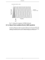
The following diagram illustrates the main concept behind OFDM. The available frequency spectrum
is divided into subchannels. Each subchannel is orthogonal, meaning that the peak signal strength of
each signal occurs at the null or point of minimum signal strength of its neighbor, so adjacent
subchannels do not interfere with each other. Data is carried in parallel across the subchannels.
4
Description
Fig. 2.1. Orthogonal Arrangement of OFDM Subchannels
2.1.4. About Point-to-Multi-Point (P-MP) Systems
Two kinds of equipment are required for a wireless P-MP link: Access Point (AP) equipment and
Customer Premise Equipment (CPE). AP equipment is located at the service provider’s site and CPE
equipment is located at the customer’s site. The LibraPlus P-MP product is available as an AP, a CPE
with integrated 23 dBi antenna or an LCPE for connection to higher gain external antennas.
5
Description
Fig. 2.2. LibraPlus P-MP System Components
2.1.4.1. Point to Multipoint based on CSMA
A CSMA/CA (Carrier Sense Multiple Access With Collision Avoidance) system will require that all
remote stations be able to hear one another. If any one station in the system cannot hear all the rest of
the stations, collisions will most likely occur. A CSMA station will first listen to the air, if it hears no
other station transmitting, then it will start transmitting. If a CSMA station hears another station's signal
it waits until the transmission halts. If any one station is "out of range" of another station it is quite
possible for them both to attempt to transmit at the same time, resulting in collisions.
The CSMA/CA protocol has severe limitations in many multipoint applications. The biggest problems
arise when the data traffic load is high; that is, when every station has a lot of data to send at the same
time. This can lead to every station being in Collision Avoidance mode and the link is unlikely to be
optimally utilized.
CSMA/CA does not share the available bandwidth fairly; a site with a strong signal has a great advantage
over a site with a weak signal. This is termed "capture effect" and results in one site gaining more
share of the available bandwidth during transmission. Finally, CSMA/CA bridging devices also experience problems when some sites in a network are not within listening distance of some other sites on
the network. This can lead to two or more sites attempting to transmit at the same time, resulting in
transmission collisions.
6
Description
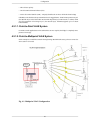
2.1.4.2. LibraPlus 5845 Adaptive Polling Protocol
The LibraPlus solves all the issues related to CSMA/CA by using a Proprietary Adaptive Polling RF
protocol that provides Media Access Control (MAC) for the Access Point and the remote users to appropriately share the RF channel.
The Adaptive Polling Proprietary Protocol is a polling-based protocol. In brief, the Access Point performs a central control on the RF channel by polling the remote users (subscribers) in a round-robin
fashion. If the polled user has data to send, then it immediately sends the data to the base station; otherwise, it keeps silent, in which case the base station will timeout and then starts to poll the next user.
Remotes need not have a communication path between them. With this adaptive polling action occurring,
each station gets their opportunity to transmit data to the master station. This is done in a sequential
format, first remote station#1, then #2, then #3 etc. When all remotes have been given their opportunity
to communicate, the process repeats itself, again and again.
The LibraPlus 5845 uses intelligence to determine the number of polling cycles every user gets depending on the level of its activity. This way the network resources are not wasted during the polling of
inactive users due to no user data transmission. A mechanism is also provided for an inactive user to
become active and to resume its data transmission. The variation of polling cycles also has the potential
support greater total number of CPEs.
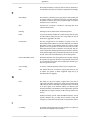
2.1.4.3. Access Point (AP) Equipment
The AP controls communication within the wireless network and is the main access point to the Ethernet.
The access point communicates with the CPE’s in the system to provide each CPE with Access to the
main network (i.e. Ethernet). The access point is typically located at a distance away from the CPE
that will provide adequate radio signal strength for the specified data rates.
The Access Point is responsible for any CPE data management functions.
The LibraPlus AP consists of three parts: 1) AP radio unit, 2) Ethernet Power Inserter with CAT-5
cable (bought separately) and weatherproofing kit (included), and 3) the External Antenna and cable
(both bought separately).
• LibraPlus AP. The AP is the main piece of radio equipment. It is designed for outdoor installation
but can also be installed indoors if needed. The AP is equipped with an N-type (F) RF connector so
that the external antenna can be connected to it. Thus many different types of base stations can be
deployed using sectoral, omni or other specialized antennas.
• Ethernet Power Inserter.
This piece of equipment is a small box that connects between the
CPE and the P.C. This box also provides power for the AP equipment to run. A CAT-5 outdoor
cable is used to connect the Power inserter to the AP. The weatherproofing kit is used with standard
RJ-45 connector to ensure reliable connection for outdoor systems.
• Antenna and Cable.
In order to accommodate different frequency re-use plans and scalability
of the base stations the AP is designed to be used with an external antenna. Antennas and cables are
selected by the user based on the network requirements.
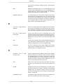
2.1.4.4. Customer Premise Equipment (CPE)
The CPE equipment connects customers to the AP via a wireless link. The link enables customers to
communicate with other users of the wireless network and the Ethernet. Customer Premise Equipment
has two parts: 1) CPE radio unit and 2) Ethernet Power Inserter with CAT-5 cable (bought separately)
and weatherproofing kit (included).
7
Description
• LibraPlus CPE. The CPE is the main piece of equipment that would normally be installed outdoors (indoor installation is permitted when feasible) The CPE contains all of the necessary radio
equipment to provide a high-speed wireless link. The CPE also has an integral antenna such that no
RF cables are required for a typical installation.
• Ethernet Power Inserter.
This piece of equipment is a small box that connects between the
CPE and the P.C. This box also provides power for the CPE equipment to run. A CAT-5 outdoor
cable is used to connect the Power Inserter to the CPE. The weatherproofing kit is used with standard
RJ-45 connector to ensure reliable connection for outdoor systems.
Wireless network activity focuses on the AP, which is both the main access point to the Ethernet (LAN
or WAN) and the destination for CPE-originated communications (CPEs do not communicate directly
with other CPEs—they communicate only via the AP). CPEs complete the customer-end of a wireless
link.
2.1.4.5. Long Range Customer Premise Equipment (LCPE)
The LCPE equipment also connects customers to the AP via a wireless link. The LCPE enables the
customer to reach longer ranges by allowing the connection to a higher gain external antenna. It can
also be used for indoor installation of the units should severe weather conditions require it. The antenna
is then mounted outdoors and connected via appropriate RF cables to the unit. One other alternative
which customers may want to consider is to use lower gain antennas with systems that are very close
to the Base Station to mitigate some interference concerns without recourse to dynamic power control.
The LibraPlus LCPE consists of three parts: 1) LCPE, 2) Ethernet Power Inserter with CAT-5 cable
(bought separately) and weatherproofing kit (included), and 3) the External Antenna and cable (both
bought separately).
• LibraPlus LCPE. The LCPE is the main piece of equipment. It is designed for outdoor installation
but can also be installed indoors if needed. The LCPE is equipped with an N-type connector so that
the external antenna can be connected to it. Thus the range of the P-MP system can be significantly
increased by use of higher gain antennas. Also, in situations where very severe conditions may be
encountered outdoors the LCPE can be installed indoors with cabling to the antenna outside.
• Ethernet Power Inserter.
This piece of equipment is a small box that connects between the
LCPE and the P.C. This box also provides power for the LCPE equipment to run. A CAT-5 outdoor
cable is used to connect the Power inserter to the LCPE. The weatherproofing kit is used with
standard RJ-45 connector to ensure reliable connection for outdoor systems.
• Antenna and Cable.
In order to accomodate different range requirements for P-MP links, the
LCPE is designed to be used with an external antenna. Antennas and cables are selected by the user
based on the network requirements.
2.1.4.6. Radio Operation Background
The LibraPlus communicates using a technique call Time Division Duplexing (TDD) in both the P-P
and P-MP configurations. TDD uses one frequency for both the Down Link (DL) Transmission (Base
to Remote in P-P, or AP to CPEs in P-MP), and for the Up Link (UL) (Remote to Base in PP or CPEs
to AP in P-MP). The DL and UL transmissions are performed at different times, therefore the system
is known as a Time Division Duplexing system. The available frequency band is therefore separated
into multiple TDD channels allowing for use of the whole frequency bands for very high capacity.
8
Description
Fig. 2.3. Time Division Duplexing Channels
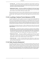
In addition to using TDD, in a P-MP system, the AP and CPE also use Time Division Multiplexing
(TDM). TDM is a process of using time slots to allow the AP to transmit to multiple CPEs during a
single transmit cycle. During the Up Link cycle each CPE is polled and if it has data it transmits in
turn. This is known as Time Division Multiple Access (TDMA). All CPEs thus share the bandwidth
available by allocating time slots in turn to each of the units on both transmit and receive channels.
The following diagram shows TDM in a DL and TDMA in the UL. Each slot is allocated to a different
CPE. In the EION system each slot may vary in time depending on traffic destined for each of the
CPEs. CPEs that are not very active will also be polled less frequently thus reducing the latency of the
system. Once they are ready to transmit or receive they will move up the polling list and will be polled
more often.
Fig. 2.4. Time Division Multiplexing/Time Division Multiple Access (TDM/TDMA)
Antenna characteristics and placement are critical. Because of OFDM’s excellent Non-Line of Sight
performance and its resistance to frequency selective multipath fading CPE directional antennas do
not have to be pointed directly at the AP antenna. Having a clear line of sight is always preferable, but
is not necessary with the LibraPlus series. There are cases in which the optimal performance is achieved
when the CPE antenna does not point directly to the AP (e.g. when using reflection off a nearby
structure to avoid an absorbing obstruction).
2.1.4.7. Quality of Service (QoS)
In the LibraPlus 5845 Quality of Service QoS is achieved through the provisioning of the WMM
(Wireless MultiMedia Extensions). WMM prioritizes traffic according to four Access Categories (AC)
- voice, video, best effort, and background. WMM creates QoS for traffic priority management to timesensitive applications such as voice, video and multimedia traffic. A WMM QoS scheme can be further
enhanced through the use of VLAN customer separation.
2.1.5. About Point-to-Point (P-P) Systems
For P-P systems LibraPlus comes in two versions, the Rapid Deployment (RD) and the Extended
Range (ER) units. P-P links are used when only two locations are connected, for example for backhaul
purposes between P-MP Base Stations and the Network Operating Center for connection to the Internet
backbone, or in situations where throughput requirements between two locations are such that the
bandwidth can’t be shared.
9
Description
2.1.5.1. DenFlow Proprietary Protocol
DenFlow is a proprietary protocol that enhances LibraPlus 5845 performance and security for radios
in a Point-to-Point configuration. With DenFlow, the radios will dynamically report and optimize the
productivity of channels for PTP communication. The Denflow protocol improves system performance
and work to protect the link against interference.
2.1.5.2. Rapid Deployment (RD) Equipment
The RD equipment is intended for very rapid installation of a P-P link and can be used for links of up
to 25 kms (up to 3 kms at full 45 Mbps actual bandwidth). RD Equipment has two parts: 1) RD and
2) Ethernet Power Inserter with CAT-5 cable (bought separately) and weatherproofing kit (included).
• LibraPlus RD. The RD is the main piece of equipment that is normally installed outdoors (indoor
installation is permitted when the range and link budget allows it). The RD contains all of the necessary radio equipment to provide a high-speed wireless link. The RD also has an integral 23 dBi antenna such that no RF cables are required for a typical installation.
• Ethernet Power Inserter. This piece of equipment is a small box that connects between the RD
and the Ethernet network. This box also provides power for the RD equipment to run. A CAT-5
outdoor cable is used to connect the Power inserter to the RD. The weatherproofing kit is used with
standard RJ-45 connector to ensure reliable connection for outdoor systems.
2.1.5.3. Extened Range (ER) Equipment
The ER Equipment allows for the use of different external antennas to achieve links of much longer
range (up to 50 kms). It can also be used for indoor installation of the units should severe weather
conditions require it. The antenna is then mounted outdoors and connected via appropriate RF cables
to the unit.
The LibraPlus ER consists of three parts: 1) ER, 2) Ethernet Power Inserter with CAT-5 cable (bought
separately) and weatherproofing kit (included), and 3) the External Antenna and cable (both bought
separately).
• LibraPlus ER.
The ER is the main piece of equipment. It is designed for outdoor installation
but can also be installed indoors if needed. The ER is equipped with an N-type connector so that
the external antenna can be connected to it. Thus the range of the P-P system can be significantly
increased by use of higher gain antennas. Also, in situations where very severe conditions may be
encountered outdoors the ER can be installed indoors with cabling to the antenna outside.
• Ethernet Power Inserter. This piece of equipment is a small box that connects between the ER
and the Ethernet network. This box also provides power for the ER equipment to run. A CAT-5
outdoor cable is used to connect the Power inserter to the ER. The weatherproofing kit is used with
standard RJ-45 connector to ensure reliable connection for outdoor systems.
• Antenna and Cable.
In order to accommodate different range requirements for P-P links, the
ER is designed to be used with an external antenna. Antennas and cables are selected by the user
based on the network requirements.
2.1.6. Hardware
This section describes the LibraPlus hardware. Although antennas are part of the equipment in general,
antennas are not discussed here. The LibraPlus product has one connector Power/Ethernet Port on the
back panel common for all types of LibraPlus equipment. The AP, ER and LCPE units also have a
female N-Type connector on the front panel for connection to the antenna.
10
Description
Fig. 2.5. LibraPlus Connection Panel
1. Power/Ethernet Port.
Standard RJ 45 Ethernet Connector. A weatherproofing kit is provided
with the unit, so that standard outdoor CAT-5 cable can be used.
2. Serial Port. 5-pin female connector. A matching connector and cable is available separately for
local configuration.
Fig. 2.6. CAT-5 Weatherproofing Kit
Fig. 2.7. Round Cable Bead
11
Description
Fig. 2.8. LibraPlus AP, ER and LCPE Front Panel RF Connector
Fig. 2.9. Ethernet Power Inserter
1. To Ethernet LAN
2. To LibraPlus Radio
Caution
Before connecting the LibraPlus to a power source, ensure that you are using the correct
power supply for your radio. LibraPlus radios with a mfg rls number prior to B0 require a
different power supply. Contact your distributor for details.
12
Description
Fig. 2.10. Mounting
Fig. 2.11. Large Pipe Diameter Mounting Configuration
13
Description
Fig. 2.12. Small Pipe Diameter Mounting Configuration
Fig. 2.13. Wall Mounting Configuration
14
Description
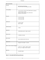
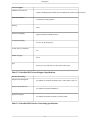
2.1.7. Specifications
15
Description
Radio Specifications
Topology
RD, ER: Point-to-Point (PtP)
AP, CPE, LCPE: Point-to-Multipoint (PtMP)
Coverage/Range
AP: up to 20 km (12 miles) with 36 dBi antenna on CPE side
CPE: up to 5 km (3 miles)
ER: up to 50 km (30 miles) with 36 dBi antenna
RD: up to 10 km (6 miles)
Frequency
5.150 to 5.320 GHz
5.470 to 5.725 GHz
5.745 to 5.825 GHz
Channel Size
Normal: 20 MHz
Turbo: 40 MHz
Channel Spacing
20 MHz
Modulation
OFDM: BPSK, QPSK, 16QAM, 64QAM
Antenna Gain
23 dBi (RD, CPE only)
RF Connector
N-type female (ER, AP, LCPE only)
Output Power
Adjustable from 0 dBm to +28 dBm
Effective Point-to-Point Throughput
Normal: up to 30 Mbps (20 MHz Channel)
Turbo: up to 45 Mbps (40 MHz Channel)
Duplexing
TDD; Half-Duplex
Table 2.1. LibraPlus 5845 Radio Specifications
16
Description
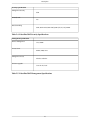
Network Support
Medium Access Protocol
Adaptive Polling/Dynamic TDMA (Point-to-Multipoint), DenFlow (Point-to-Point)
Network Connection
10/100 Base T Auto-Negotiate
Routing
Static
Intra-Sector Bridging
Supported (Point-to-Multipoint only)
Transparent Bridging
Yes, 802.1q tag transparency
VLAN (802.1q) compliance
Yes
RADIUS Support
802.1x
QoS
Priority for voice and video over data; MAC and IP Layer
Table 2.2. LibraPlus 5845 Network Support Specifications
Wireless Networking
Output Power Management
Yes, Manual or Automatic Transmit Power Control (ATPC), 802.11h
Dynamic Speed Selection
Yes, Manual or Dynamic Modulation
Dynamic Frequency
Yes, Manual or Dynamic Frequency Selection (DFS)
Table 2.3. LibraPlus 5845 Wireless Networking Specifications
17
Description
Security Specifications
Management Security
SSH
Firewall, NAT
Yes
Data Scrambling
WPA, WPA-EAP (TKIP AES),WEP (64,128,154), MPPE
Table 2.4. LibraPlus 5845 Security Specifications
Management Specifications
Remote Management
CLI, SNMP
Access Server
PPPoE, PPtP, VPN
Management Access
Wireless and Wire
Software Upgrade
Over the Air, local
Table 2.5. LibraPlus 5845 Management Specifications
18
Description
Physical, Electrical and Environmental Specifications
Form-Factor
AP, LCPE, ER: Outdoor, rugged
RD, CPE: Outdoor, antenna integrated
Enclosure
AP, LCPE, ER: Die-cast with metal plate cover
RD, CPE: Die-cast with plastic antenna housing
Dimensions
AP, LCPE, ER: 230 (w) x 65 (d) x 230 (h) mm
RD, CPE: 300 (w) x 90 (d) x 300 (h) mm
Weight
AP, LCPE, ER: 2.0 kg
RD, CPE: 2.3 kg
Mounting Bracket
Yes, 2-Axis pole/wall
Power Consumption
15 W MAX
Input Voltage
100/240V, 50/60 Hz AC
Operating Temperature
-35° C to +80° C
Relative Humidity
0 to 100%, condensing
Certifications
Enclosure: NEMA 4x; Designed to IP66
Environmental: RoHS and WEEE
IC: RSS-210, ISS-03, 8367A-5845001
FCC Part 15.247, subpart C, 15.203, 15.207 (2007), 15.109, 15.407
ETSI EN 301 489-1, EN 301 893, EN 301 489-17 (EMC Wideband data and HIPERLAN
EN 50385-2002, EN 55022, EN 61000
Safety: UL 60950 equivalent EN60950 (EU); Modular approvals (electrical)
Lightning Protection
Integrated, Telcordia GR-1089 compliant (Meets IEC 61000-4-2/ 4-4)
19
Description
Table 2.6. LibraPlus 5845 Physical, Electrical and Environmental Specifications
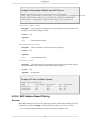
2.2. System Applications
2.2.1. Making a Simple Wireless Bridge
The simplest example of using a LibraPlus Radio is a point-to-point wireless bridge that connects two
wired network segments or LANs. Two LibraPlus units are required: a Master (AP) and Slave (Station).
Fig. 2.14. Point-to-Point Wireless Bridge
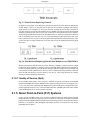
2.2.2. Creating a Simple Wireless Network
You can create a point-to-multipoint wireless network by adding several CPEs to a single AP.
20
Description
Fig. 2.15. Point-to-Multipoint Wireless Network
21
Chapter 3. Field Installation
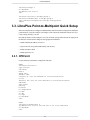
3.1. Introduction
The information in this chapter is intended for qualified installers only.
Warning
All antennas and equipment must be installed by a knowledgeable and professional installer. NOTE: EION RECOMMENDS THE USE OF LIGHTNING SUPRESSORS IN
ALL INSTALLATION.
The information in this chapter is intended for qualified installers only. Before you begin to install
equipment in the field, you should develop a network plan, prepare the customer site, and configure
the equipment. The network plan describes the proposed system, including a link budget, detailed list
of all required hardware, LibraPlus units (RD and ER for P-P links; LCPE, CPE and Access Point for
P-MP), antenna locations, cable routing, equipment configuration settings, and other network requirements. (EION, Inc. offers Network Planning and Site Preparation support. For more information on
services and fees contact your Sales Representative or visit http://www.eionwireless.com/). Network
planning should include visits to proposed sites to verify the feasibility of the network plan and work
out the details. Installers will use the network plan document to guide them through final site preparation,
installation, configuration and field testing of each unit. You can see that a large amount of planning
and preparation work is required before equipment is ready to install. The better the preparation work,
the more problem-free the field installation will be.
Fig. 3.1. Installation Process
3.2. LibraPlus Point-to-Point Quick Setup
This section explains how to configure a pair of LibraPlus radios for simple point to point communication. Using this example will configure a link without any additional features such as security, routing,
filtering, or VLAN
Note that the distance in this example is set to 300 for bench testing. When the units are deployed in
the field, this value should be changed to the appropriate link distance.
• Default LibraPlus IP address 192.168.0.5
• Login to the unit using a SSH enabled utility such as Putty
• Default username: admin
• Default password: 123
Note
For quick configuration, copy and paste the commands listed below directly into the SSH or
serial interface of the radio.
22
Field Installation
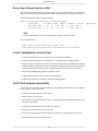
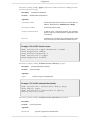
3.2.1. Slave (RD or ER) Unit
Use the following commands to configure the Slave (RD or ER) side of the point to point link.
interface wireless 0
type station
no shutdown
mode a
channel 5805
tx-power 26
speed auto
wds-mode
distance 300
ssid papasam
exit
interface FastEthernet 0
ip address 192.168.0.5 255.255.255.0
no shutdown
exit
interface bridge 0
no shutdown
ip address 192.168.0.5
exit
interface wireless 0 bridge-group 0
interface FastEthernet 0 bridge-group 0
copy running-configuration startup-configuration
reboot
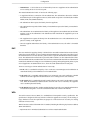
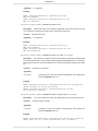
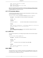
3.2.2. Master (RD or ER) Unit
Use the following commands to configure the Master (RD or ER) side of the point to point link.
interface wireless 0
type ap
no shutdown
mode a
channel 5805
tx-power 26
speed auto
wds-mode
distance 300
ssid papasam
exit
interface FastEthernet 0
ip address 192.168.0.1 255.255.255.0
no shutdown
exit
23
Field Installation
interface bridge 0
no shutdown
ip address 192.168.0.1
exit
interface wireless 0 bridge-group 0
interface FastEthernet 0 bridge-group 0
copy running-configuration startup-configuration
reboot
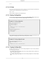
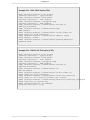
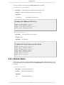
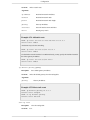
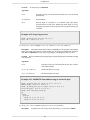
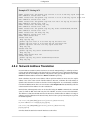
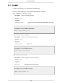
3.3. LibraPlus Point-to-Multipoint Quick Setup
This section explains how to configure a LibraPlus Master and Client radio for simple point to multipoint
communication. Using this example will configure a link without any additional features such as security, routing, filtering, or VLAN
Note that the distance in this example is set to 300 for bench testing. When the units are deployed in
the field, this value should be changed to the appropriate link distance.
• Default LibraPlus IP address 192.168.0.5
• Login to the unit using a SSH enabled utility such as Putty
• Default username: admin
• Default password: 123
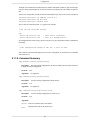
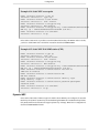
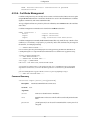
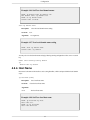
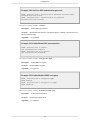
3.3.1. CPE Unit
Use the following commands to configure the CPE side.
EION:
interface wireless 0
type station
ssid Eion
mode a
speed auto
channel 5805
tx-power 26 (use the maximum if field installation)
no rts
distance 300 (use the real distance if field installation)
wds-mode
fast-frame
polling
no burst
no compression
no wmm
no dfs
no atpc
no shutdown
exit
EION:
interface FastEthernet 0
ip address 192.168.0.5 255.255.255.0 (IP to be modified)
no shutdown
exit
24
Field Installation
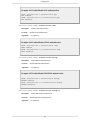
EION:
interface bridge 0 (create the bridge)
interface bridge 0 (enter the bridge interface)
no shutdown
ip address 192.168.0.5 255.255.255.0 (IP to be modified)
exit
EION:
interface wireless 0 bridge-group 0
interface FastEthernet 0 bridge-group 0
copy running-config startup-config
reboot
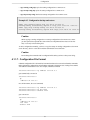
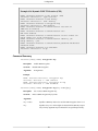
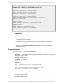
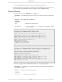
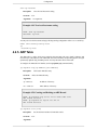
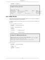
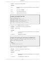
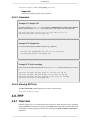
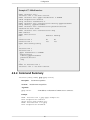
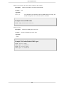
3.3.2. AP Unit
Use the following commands to configure the AP Unit.
EION:
interface wireless 0
type ap
ssid Eion
mode a
speed 54 (put speed ‘auto’ for variable signal strength)
channel 5805
tx-power 5 (use the maximum if field installation)
no rts
distance 3000 (use the real distance if field installation)
wds-mode
fast-frame
no burst
no compression
no wmm
no dfs
no atpc
polling (enable the polling mechanism)
polling-max-station 3 (the number of CPEs to be associated with the AP)
polling-txtimeslot 40
polling-rxtimeslot 40
no shutdown
exit
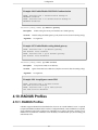
EION:
interface FastEthernet 0
ip address 192.168.0.1 255.255.255.0 (IP to be Modified)
no shutdown
exit
EION:
interface bridge 0 (create the bridge)
interface bridge 0 (enter the bridge interface)
no shutdown
ip address 192.168.0.1 255.255.255.0 (IP to be modified)
exit
EION:
interface wireless 0 bridge-group 0
interface FastEthernet 0 bridge-group 0
25
Field Installation
copy running-config startup-config
reboot
3.4. LibraPlus Field Installation
This section discusses how to install, configure and test a LibraPlus in the field.
Before you can install LibraPlus equipment in the field:
• All units should be configured as described in the Configuration section
• Site preparation work must be complete
• Ensure all necessary tools and equipment are available
3.4.1. Site Preparation
Site preparation involves checking actual customer site conditions and ensuring that the site is ready
for LibraPlus installation. Each site is unique, however the following guidelines are provided.
1. Obtain a customer site plan or make a site plan. This document should describe where to place the
LibraPlus unit, what kind of equipment to use, and the required configuration settings of the unit.
2. Cables should always be connected without exceeding their recommended bend radius.
3. Ensure that there is enough room for ventilation.
4. Confirm that AC power and Ethernet access are available.
5. Inspect the recommended LibraPlus location to determine the following:
• the mounting structure is suitable;
• LOS and Fresnel Zone clearances can be met, because of OFDMs superior Non Line of Sight
performance these requirements will not be as stringent as for other systems;
• location of the LibraPlus is acceptable.
6. Check cable routes and entry and exit points to ensure that they are practical.
3.4.2. Tools and equipment
You will require the following tools and equipment
• Standard tool kit
• Test equipment
• Drill and bits
• LibraPlus Unit
• Weatherproofing materials
• LibraPlus mounting hardware
• Ladder
• Cables: Outdoor CAT-5 Cable, AC power cable.
26
Field Installation
• Compass or GPS
• Customer acceptance form and Installation record, if required
• Binoculars
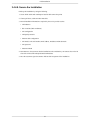
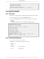
3.4.3. LibraPlus Package Checklist
• 1x LibraPlus Unit (with Integrated Antenna (CPE, RD units) or without (AP, LCPE, ER))
• 1x Power Cord
• 1x Power Inserter
• 2x Round Ferrite Bead
• 1x Mounting Kit
• 1x Mounting base
• 1x Wall Mount Clamp
• 1x Clamp
• 1x Arm
• 4x Washer Flat M5
• 4x Washer Spring M5
• 4x Nut M5
• 4x Screw Hex Cap M5x0.8 16mm
• 6x Washer Flat M8
• 4x Washer Spring M8
• 2x Nut M8
• 4x Screw Hex Cap M8x40 (for 1 3/4" dia pole)
• 4x Screw Hex Cap M8x70 (for greater than 1 3/4" dia pole)
• 1x Weather Proof Kit
• 1x O Ring
• 1x Insert
• 1x Coupling Nut
• 1x LibraPlus Documentation CD
Caution
Do not "hot plug" the power inserter into the LibraPlus to power up the unit – the LibraPlus
CAT-5/Power connector should first be plugged into the unit at the DIN connector, and into
the "TO RADIO" jack of the power inserter. Next, the power supply cord should be plugged
into the AC outlet to power up the unit.
27
Field Installation
Warning
Do NOT plug the LAN RJ45 cable into the power inserter marked "TO RADIO", as this port
has power and may damage external equipment.
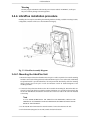
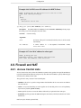
3.4.4. LibraPlus installation procedure
Installing the CPE requires assembling the mounting hardware, finding a suitable mounting location,
configuration, and then a link test to check the RF link integrity.
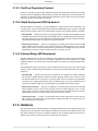
Fig. 3.2. LibraPlus Assembly Diagram
3.4.4.1. Mounting the LibraPlus Unit
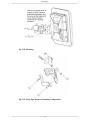
1. Mount the clamps without the LibraPlus unit to the pole or wall as required. The versatile mounting
hardware can be used with large diameter and small diameter poles or as a wall mount. Additionally
an optional knuckle is provided that allows for both pan and tilt functionality while the mounting
clamp is firmly fixed to the pole or wall. See Hardware section for detailed diagrams of the
mounting hardware.
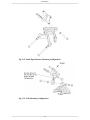
2. Connect the four pointed star bracket to the unit. Assemble the mounting kit. Ensure that this connection is in the right direction so that the antenna polarization is as specified in the network plan
for the CPE and RD units and that the connectors are on the lower side of the unit when mounted
to the clamp.
Note
IF YOU NEED HORIZONTAL OR VERTICAL POLARIZATION. MOUNT THE
LIBRAPLUS ACCORDING TO THE POLARIZATION STICKER LOCATED ON THE
BACK OF THE ANTENNA.
3. For the AP, ER and LCPE mount the external antenna. Connect the antenna to the unit.
4. Point the antenna (Integrated or external) towards the desired location.
28
Field Installation
5. For the CPE or RD, if Up or Down tilt is required, adjust the unit accordingly such that the face of
the antenna is pointed as directly to the Access Point or the other unit in the P-P link as possible.
6. Lightly tighten the bracket bolts to hold the unit in place.
3.4.4.2. Connecting the LibraPlus
1. Insert the end of the CAT-5/Power cable into the provided weatherproofing attachment.
2. Connect the CAT-5 / Power cable to the connector located on the back panel of the LibraPlus Unit
and screw in the weatherproofing attachment.
3. Install two round ferrite cable beads over the Ethernet cable at the PoE side. The ferrite beads slide
onto the Ethernet cable over the RJ-45 connector. For adequate suppression two cable beads are
required.
4. Plug the RJ-45 end of the LibraPlus CAT-5 cable into the power inserter in the "TO RADIO" jack.
When this connection is made, the LibraPlus will produce an audible tone for approximately 30
seconds.
5. Connect the "TO LAN" side of the power inserter to the PC or network.
6. Locate the AC power cord for the power inserter and plug AC power cord in, and to the AC wall
socket.
3.4.4.3. SSH Connection
In order to connect to LibraPlus radio using SSH you will need:
1. The Ethernet interface where the radio is connected should be on the same subnet as the radio
192.168.0.x (For example it must have an IP address like 192.168.0.100)
2. Use an SSH program to login to the radio (like Putty) the default IP address on the radio is
192.168.0.5.
3. Type the IP address of the radio and connect
4. You will be prompt to login: Default login: admin default password: 123
3.4.4.4. Serial Connection
The serial port settings for LibraPlus are as follows:
• Bits/second: 115200
• Data bits: 8
• Parity: None
• Stop bits: 1
• Flow control: None
29
Field Installation
Fig. 3.3. COM 1 Propertries
You will be prompt to login:
Default login: admin default password: 123
3.4.4.5. Antenna Alignment
The LibraPlus has an audible tone (beeper) and an integrated signal strength indicator (watch) to aid
in antenna alignment.
Audible Tone (Beeper)
The procedure for using the audible tone is the same for the AP and CPE. Use the ‘beeper’ command
to activate the audible tone. The LibraPlus unit will produce a series of beeps when it detects a signal.
As the signal strength increases, the frequency of the beeping will increase. Use the ‘beeper’ command
as shown below to activate the audible tone for a chosen interface.
EION: interface Wireless 0 beeper
Beeper is turned on.
Use the no-form of the ‘beeper’ command to deactivate the audible tone:
EION: interface Wireless 0 no beeper
Beeper is turned off
30
Field Installation
Receive Signal Strength Indicatior (RSSI)
The 'associated' command shows the signal strength and noise levels for radios in the same bridge
group. To see close to real time RSSI, add the "watch" command after the "associated" command.
AP antenna alignment using the ‘watch’ command:
EION: show interface Wireless 0 associated watch
Client MAC
Id Speed RSSI Signal Inactive TX
0015.6d63.4df8 1 54
60
-35 120
2 56576 Ecs
0015.6d63.641a 2 54
59
-36 120
2 37456 Ecs
RX
F
F
Note
The Client MAC address refers to the wireless MAC address of the CPE or slave
CPE, LCPE, RD or ER:
EION: show interface Wireless 0 signal watch
Link Quality=54/94 Signal level=-41 dBm Noise level=-95 dBm
3.4.4.6. Configuration and Link Test
1. Connect a laptop to the "TO LAN" side of the power inserter the LibraPlus.
2. Configure unit to the proper center frequencies, etc. if you have not done that previously
3. If the link results are satisfactory, proceed to Step 6 below. If the link is unsatisfactory first turn the
antenna in different directions to benefit from beneficial multi-paths. If still unsuccessful look for
another antenna location with better line-of-sight until you find a location that is satisfactory.
4. Refer to the troubleshooting guidelines if problems persist.
5. Adjust antenna position to achieve the best Link performance.
6. When Link performance is satisfactory, tighten mounting hardware.
3.4.4.7. Test network connectivity
The next step is to verify that a computer attached to the LibraPlus can communicate with a computer
on the other side of the wireless link.
1. Call up the Network Operations Center (NOC).
2. "Ping" the NOC from the CPE.
3. Have the NOC "ping" the CPE from the NOC. A successful ping test means that the network "sees"
the CPE on the network.
4. Connect the CPE Ethernet Port to the customer LAN or PC.
5. Ping from the Customer LAN or PC to the NOC.
6. Use ftp to send some larger test files from the NOC to the PC or other IP device on the LAN.
7. Measure file transfer rates in both directions.
31
Caps Flags
Field Installation
3.4.4.8. Secure the Installation
Finish up the installation by doing the following.
1. Secure all the cables and weatherproof outside cable connection points
2. Clean up all boxes, cables and other materials.
3. Record installation information as required by the service provider such as
• Link Distance
• Site Locations (GPS coordinates)
• Unit configuration
• Link quality statistics
• Antenna cable configuration
• Unit model, Unit serial number, MAC address, IP address and IP submasks
• Unit password
• Antenna azimuth
4. Demonstrate to the customers that the installation works and that they can contact sites on the far
side of the wireless link and upload and download data.
5. Have the customers sign a document to indicate their acceptance of the installation.
32
Chapter 4. Configuration
4.1. Getting Started
4.1.1. LibraPlus Configuration Management
4.1.1.1. Configuration types
The primary method for configuring LibraPlus system is through a command line interface (CLI). The
LibraPlus system configuration file is a set of commands that sets the system to the desired state right
after the startup.
There are three types of configuration available with the LibraPlus :
1. Default configuration is supplied by the manufacturer. It is used to reset the system to factory
defaults.
2. Running configuration is a command set that has to be executed to turn the system to the current
state. Running configuration is stored in RAM and reflects every change of the system settings.
However, the contents of RAM are lost when the system is powered down. In order to save the
current state of the system, copy the running configuration to the startup file, see below.
3. Startup configuration is used by the system to configure itself during initialization. Startup configuration is stored in non-volatile flash memory.
4.1.1.2. Default Login
1. Access the unit using an SSH client (or HyperTerminal over serial connection).
2. Login to the unit with the administrator username and password.
Factory defaults
• username: admin
• password: 123
4.1.1.3. CLI Auto Complete
The command interpreter in the LibraPlus 5845 is designed to accommodate both a novice as well as
an expert operator. All commands and parameters have descriptive names so that they are easily remembered and their meaning is clear. In order to be descriptive however, those commands are sometimes
long. As the operator becomes familiar with the command language, typing the complete words could
become cumbersome. The LibraPlus command interpreter recognizes any abbreviations to commands
and parameter names, as long as they are unambiguous. If an ambiguous command is entered, the radio
will not take any action.
To verify that a command is unambiguous, enter the abbreviated form and press the tab key. The
command interpreter will immediately display the closest matching command. If this is not the command
you are looking for, then you have not typed enough of the command to make it unambiguous. Press
the tab key to cycle through all of the matching commands.
Using these auto complete rules, the command
show interfaces
can be abbreviated as
33
Configuration
sh in
.
4.1.1.4. CLI Help
The CLI has a built in help function with each command. To access the help topic associated with a
command, type the command followed by a question mark e.g.
EION: show?
and the LibraPlus will display the associated help topic.
4.1.1.5. Viewing Configuration
To view the current running configuration of the system, the show running-config command is used.
To view the startup configuration, the show startup-config command is used.
Example 4.1. Viewing configuration
EION: show running-config
interface Bridge 0
interface Bridge 0
ip
address 192.168.1.1 255.255.255.0
no shutdown
!
interface FastEthernet 0
bridge-group 0
no shutdown
!
These commands can take an optional search key, which allows for viewing only desired parts of the
configuration. The Displayed part contains matched strings and their value(s).
Example 4.2. Viewing configuration part
EION: show running-config ip
interface Bridge 0
ip
address 192.168.1.1 255.255.255.0
4.1.1.6. Copying Configuration
The copy command branch is used to save the running configuration or reset it to factory defaults. It
has the following subcommands:
• copy default-config startup-config resets the device to factory defaults. After the command is executed, a soft reboot is required.
• copy running-config startup-config saves the current running configuration as a startup configuration.
34
Configuration
• copy running-config tftp copies the running configuration to a TFTP server.
• copy startup-config tftp copies the startup configuration to a TFTP server.
• copy tftp startup-config downloads a startup configuration from a TFTP server.
Example 4.3. Configuration backup and restore
EION: copy running-config tftp 192.168.0.10 eion.rc
Running-config successfully copied to tftp://192.168.0.10 'eion.rc'.
EION: copy tftp startup-config 192.168.0.10 eion.rc
Startup-config successfully copied from tftp://192.168.0.10 'eion.rc'.
Caution
While copying a running configuration or a startup configuration to the TFTP server, ensure
you have permission to upload files. Some TFTP server implementations refuse to create new
files, or can only refresh existing ones.
To edit a configuration manually, you have to copy the startup or running configuration to the TFTP
server directory, edit it in a text editor and then download the revised file back.
Caution
Do not change the command order in configuration files unless you know what you are doing.
4.1.1.7. Configuration File Format
LibraPlus configuration file is a hierarchical command set that can be converted to LibraPlus commands.
Before generating a configuration, each LibraPlus command is divided into a set of strings in accordance
with different command tree levels. For example, LibraPlus command
interface Wireless 0 ip address 192.168.0.3
gets automatically converted to
interface Wireless 0
ip
address 192.168.0.3
In a similar manner, the set of commands
interface Wireless 0 ip address 192.168.0.3
interface Wireless 0 ip mtu 1400
interface Wireless 0 channel 2442
gets converted to
interface Wireless 0
ip
address 192.168.0.3
mtu 1400
channel 2442
35
Configuration
The depth of a command level is indicated by the number of tabulation symbols or spaces in the beginning of a string. Command parts at the same level must be preceded by the same number of spaces or
tabs.
Afterall, it is still possible to put the mentioned commands directly, they will be correctly interpreted:
interface Wireless 0 ip address 192.168.0.3
interface Wireless 0 ip mtu 1400
interface Wireless 0 channel 2442
The text after an exclamation mark "!" is ignored. For example:
!
! Use our own local NTP servers.
!
ntp
server ntp-server-1.lan
! This server is primary.
server ntp-server-2.lan
! This is a backup server.
All configuration files, before being copied to a TFTP server, get a header that contains a modification
timestamp:
!
! Last configuration change at Thu Jan
!
4 10:16:10 2007
This comment is automatically updated every time the configuration is passed between a LibraPlus
and a TFTP server.
4.1.1.8. Command Summary
copy default-config startup-config
Description. Reset the startup configuration to the factory default. You must restart the device
to apply the default configuration.
N/A.
No-Form.
Arguments.
No arguments.
copy running-config startup-config
Description.
Save the running configuration to flash memory.
N/A.
No-Form.
Arguments.
No arguments.
copy running-config tftp {server} {file}
Description.
Save the running configuration to a TFTP server.
N/A.
No-Form.
Arguments.
server
TFTP server domain name or IP address.
file
Destination file name on the TFTP server.
36
Configuration
copy startup-config tftp {server} {file}
Backup the startup configuration to a TFTP server.
Description.
No-Form.
N/A.
Arguments.
server
TFTP server domain name or IP address.
file
Destination file name on the TFTP server.
copy tftp startup-config {server} {file}
Restore the startup configuration from a TFTP server.
Description.
No-Form.
N/A.
Arguments.
server
TFTP server domain name or IP address.
file
Configuration file name on the TFTP server.
show running-config [search-key]
Show the running configuration.
Description.
No-Form.
N/A.
Arguments.
Search pattern to display matched strings from the configuration.
search-key
show startup-config [search-key]
Show the startup configuration.
Description.
No-Form.
N/A.
Arguments.
search-key
Search pattern to display matched strings from the configuration.
4.1.2. Running a TFTP server
In order to backup/restore configuration files, upgrade firmware or import digital certificates; install
a TFTP server on a host or PC on the network. In Windows OS, TFTP Daemon is advised. In Linux,
You may use the TFTP server from the tftp-hpa package (OpenBSD port), as follows:
in.tftpd -L -c -u root -s {certificate_directory}
This command requires root privileges.
37
Configuration
4.2. Wireless Settings
4.2.1. Configuring Physical Layer Options
4.2.1.1. Setting Radio Mode
interface {name} {index} mode {a | auto | sturboa}
Description.
No-Form.
Specifies the IEEE 802.11 mode, which can be set to 802.1a only.
N/A.
Arguments.
mode
The mode: one of a, or auto. If the mode is set to auto, the device driver automatically
calculates the optimal mode for a given frequency and data transfer rate. Setting the radio
to "auto" is also known as dynamic modulation, or dynamic speed selection. the case
where the mode in set to sturboa, the channel size of the radio will change from 20 to 40
MHz; a static channel should be chosen for the sturboa mode to be operational (see more
detail in the channel size section).
Example 4.4. Specify IEEE 802.11 mode
EION: interface Wireless 0 mode a
The mode is set to 'a'.
4.2.1.2. Available Frequencies
show interface {name} {index} channel-list
Description.
No-Form.
Arguments.
Displays a list of supported channels.
N/A.
No arguments.
Note: Frequency availability is subject to local regulatory approval. Because of this, some of the
channels listed in this example may not be availableNote: When a frequency change is required
on the radios that are associated to the main AP the user needs to change the frequency only on
the AP side. All the associated radios will automatically adapt their frequency to the one updated
on the AP. There is no need to change the frequency on every associated radio, as all of the CPEs
frequencies will change automatically.
38
Configuration
Example 4.5. List supported channels
EION: show interface Wireless 0 channel-list
Channel:
36 : 5.180 GHz
Channel:
40 : 5.200 GHz Dynamic
Channel:
42 : 5.210 GHz Static
Channel:
44 : 5.220 GHz
Channel:
48 : 5.240 GHz Dynamic
Channel:
50 : 5.250 GHz Static
Channel:
52 : 5.260 GHz
Channel:
56 : 5.280 GHz Dynamic
Channel:
58 : 5.290 GHz Static
Channel:
60 : 5.300 GHz
Channel:
64 : 5.320 GHz
Channel:
95 : 5.475 GHz
Channel:
99 : 5.495 GHz
Channel: 103 : 5.515 GHz
Channel: 107 : 5.535 GHz
Channel: 111 : 5.555 GHz
Channel: 115 : 5.575 GHz
Channel: 119 : 5.595 GHz
Channel: 123 : 5.615 GHz
Channel: 127 : 5.635 GHz
Channel: 131 : 5.655 GHz
Channel: 135 : 5.675 GHz
Channel: 139 : 5.695 GHz
Channel: 143 : 5.715 GHz
Channel: 149 : 5.745 GHz
Channel: 152 : 5.760 GHz Static
Channel: 153 : 5.765 GHz Dynamic
Channel: 157 : 5.785 GHz
Channel: 160 : 5.800 GHz Static
Channel: 161 : 5.805 GHz Dynamic
Channel: 165 : 5.825 GHz
4.2.1.3. Setting a Specific Carrirer Frequency
interface {name} {index} channel {frequency | auto}
Description.
No-Form.
Specifies the channel carrier frequency.
N/A.
Arguments.
frequency
Specifies the carrier frequency value in megahertz. The auto keyword
is applicable to the station mode only. If the station channel is set to
auto, it scans all the supported channels for a particular SSID.
Example 4.6. Set Carrier Frequency
EION: interface wireless 0 channel 5805
Channel is set to '5805'.
39
Configuration
4.2.1.4. Setting Data Transmission Rate
interface {name} {index} speed {rate | auto}
Description.
No-Form.
Specifies the wireless data transmission rate.
N/A.
Arguments.
rate
The data transfer rate in megabits per second. IEEE 802.11a supports 6, 9, 12,
18, 24, 36, 48 and 54 Mbit/s. If you set rate parameter to auto, the chipset will
choose the best rate possible.
Example 4.7. Set data rate
EION: interface wireless 0 speed 54
Speed is set to 54 Mb/s.
4.2.2. Configuring SSID
SSID stands for Service Set Identifier. SSID is a basic parameter for IEEE 802.11 wireless network
interface. Non-empty SSID is required for AP, station and ad-hoc interface to establish wireless associations with remote devices.
interface {name} {index} ssid {ssid}
Description. In the access point mode: specifies an identifier of the service set the access point
provides. In the station mode: specifies a service set to connect to.
No-Form.
Clears the SSID setting.
Arguments.
ssid
The service set identifier.
Example 4.8. Specify Service Set
EION: interface Wireless 0 ssid ache
Interface 'Wireless 0': SSID 'ache'.
4.2.3. Configuring multiple SSID
The current LibraPlus implementation supports multiple access points (AP) and concurrent AP/station
mode operation on the same wireless network interface. The interfaces named Wireless {index}.{something} with the same {index} use the same underlying hardware, thus are limited to coexisting on the
same channel and using the same physical layer features. Each instance of an AP or station is implemented as a subinterface. Subinterfaces are identified using "." followed by a numerical subinterface
ID, so that subinterface ".0" is an alias for the master interface and non-zero IDs denote additional
subinterfaces. Each subinterface can be in either AP or station mode.
40
Configuration
Example 4.9. Configuring Multiple SSID
For example, if a master device "Wireless 0" has two subinterfaces, show interfaces output will look
like this:
Wireless 0 is up
Hardware address:
Internet address:
0015.6d54.32bb
0.0.0.0 mask 0.0.0.0
broadcast: 0.0.0.0, MTU: 1500
Type: ap, SSID: "test", Mode: 802.11a
Speed: 54 Mb/s, Access point: N/A
Channel: 2, Frequency: 2417 MHz, Tx-power: 27 dBm
RTS: off, Distance: 3000, WDS: on, FastFrame: on
Burst: on, Compression: off, WMM: on, Beacon: 100
Antenna: auto, IEEE 802.11a Protection: off
Wireless 0.2 is down
Hardware address: 0a15.6d54.32bb
Internet address: 0.0.0.0 mask 0.0.0.0
broadcast: 0.0.0.0, MTU: 1500
Type: ap, SSID: "test3", Mode: 802.11a (auto)
Speed: 0 Mb/s (auto), Access point: N/A
Channel: 0, Frequency: 0 MHz, Tx-power: 27 dBm
RTS: off, Distance: 3000, WDS: off, FastFrame: on
Burst: on, Compression: off, WMM: on, Beacon: 0
Antenna: auto, IEEE 802.11a Protection: off
Wireless 0.1 is down
Hardware address: 0615.6d54.32bb
Internet address: 0.0.0.0 mask 0.0.0.0
broadcast: 0.0.0.0, MTU: 1500
Type: ap, SSID: "test2", Mode: 802.11a (auto)
Speed: 0 Mb/s (auto), Access point: N/A
Channel: 0, Frequency: 0 MHz, Tx-power: 27 dBm
RTS: off, Distance: 3000, WDS: off, FastFrame: on
Burst: on, Compression: off, WMM: on, Beacon: 0
Antenna: auto, IEEE 802.11a Protection: off
New wireless subinterface can be created only using interface ssid command. It's possible to pick any
free ID for a new subinterface. If interface ssid is called for an existing interface or subinterface, it
just sets ssid. Before a subinterface is created, it cannot be configured:
EION: interface Wireless 0.2 type ap
No such interface 'Wireless 0.2'.
EION: interface Wireless 0.2 ssid gate12
Interface 'Wireless 0.2' created; SSID 'gate12' registered.
EION: interface Wireless 0.2 type ap
Interface 'Wireless 0.2': type 'ap'.
Each new subinterface takes AP type after creation. The type may be changed, however not all subinterface types are possible in multiple SSID mode. You can create up to 3 subinterfaces per interface.
However, only one station can be there. If the master interface has a station type, then no other subinterfaces are allowed to be created. If the master device is in AP mode, then it's possible to create one
station subinterface, and other AP subinterfaces can also be created after the station.
41
Configuration
When AP and station coexist, hardware beacon timers are disabled for the station mode. This is necessary
because concurrent AP and station operation implies the station should not modify the TSF clock for
the APs.
4.2.4. Advanced Wireless Settings
4.2.4.1. Setting Transmit Power
The LibraPlus 5845 hardware is available in two different power configurations. It is important to
verify the specific LibraPlus model you are working with before setting the power level in the firmware.
Higher transmit (TX) power essentially translates into a higher signal power at the receiver. Having a
higher signal-to-noise ratio (SNR) at the receiver reduces the bit error rate of a digital communication
link. A higher SNR can also allow a system that uses link adaptation to transmit at a higher data rate,
resulting in a system with greater spectral efficiency.
The greater the TX power, the higher the supported data rate or the more reliable the link at a given
data rate. However, transmitting at unnecessarily high power may introduce excessive interference.
The maximum transmit power is limited according to regulatory region.
interface {name} {index} tx-power {power}
Description.
No-Form.
Set the transmit power.
Reset to default.
Arguments.
power
Peak power value in dBm, integer.
Example 4.10. Setting Transmit Power
EION: interface Wireless 0 tx-power 26
The tx-power value is set to 26 dBm.
4.2.4.2. Setting Distance Parameter
The link distance parameter allows the user to tune ACK timeout which optimizes performance for a
particular distance.
The Link Distance parameter is expressed in metres. This number must be divisible by 300.
interface {name} {index} distance {distance}
Description.
No-Form.
Set the distance.
Reset to default.
Arguments.
distance
Power value in meters. The value must be divisible by 300. Valid range
is 0 to 100200.
42
Configuration
Example 4.11. Setting the Distance Parameter
EION: interface Wireless 0 distance 3000
The distance value is set to '3000 meters'.
4.2.4.3. Setting Dynamic Frequency Selection (DFS)
Dynamic Frequency Selection (DFS) is the process of detecting radar signals that must be protected
against 802.11a interference, and upon detection switching the 802.11a operating frequency to one
that is not interfering with the radar systems.
interface wireless {index} dfs
Description.
No-Form.
Arguments.
Enable DFS on the radio.
Disable DFS on the radio.
None.
Example 4.12. Enable DFS
EION: interface Wireless 0 dfs
DFS is turned on.
4.2.4.4. Setting Automatic Transmit Power Control (ATPC)
Automatic Transmit Power Control is a technical mechanism used within some networking devices
in order to prevent unwanted interference between different wireless networks. The network devices
supporting this feature are IEEE 802.11h Wireless LAN devices in the 5 GHz band compliant to the
IEEE 802.11a. The idea of the ATPC mechanism is to automatically reduce the used transmission
output power when other networks are within range. Reduced power means reduced interference
problems and increased battery capacity. The power level of a single device can be reduced by 6 dB
which should result in an accumulated power level reduction (the sum of radiated power of all devices
currently transmitting) of at least 3 dB (which is half of the power).
interface wireless {index} atpc
Description.
No-Form.
Arguments.
Enable ATPC on the radio.
Disable ATPC on the radio.
None.
43
Configuration
Example 4.13. Enable DFS
EION: interface Wireless 0 atpc
ATPC is turned on.
4.2.5. Wireless Security Settings
4.2.5.1. Wireless Security Overview
Wireless networks are insecure, because they are vulnerable to attacks which are more difficult to
launch in the wired domain. Many wired networks benefit from their inherent physical security properties. For example, it is unlikely that an adversary will dig up the cable and splice into the line.
However, wireless communications are difficult to protect; they are by nature a broadcast medium. In
a broadcast medium, adversaries can easily eavesdrop on, intercept, inject, and alter transmitted data.
In addition, adversaries can interact with the network from a distance by using expensive radio transceivers and powerful workstations.
The wireless industry has created a wide range of security technologies to provide confidentiality
comparable to that of a traditional wired network.
WEP
WEP was the first attempt of IEEE 802.11 developers to protect wireless communication from eavesdropping (confidentiality), prevent unauthorized access to a wireless network (access control) and
prevent tampering with transmitted messages (data integrity). WEP uses the RC4 stream cipher,
combining a 40 bit WEP key with a 24 bit random number known as an Initialization Vector (IV) to
encrypt the data. The sender XORs the stream cipher with the actual data to produce ciphertext. The
packet, combined with the IV with the ciphertext, is sent to the receiver. The receiver decrypts the
packet using the stored WEP key and the attached IV.
Unfortunately, the encryption protocol had not been subjected to a significant amount of peer review
before release. Serious security flaws were present in the protocol. Although the application of WEP
may stop casual sniffers, experienced hackers can crack the WEP keys in a busy network within
15 minutes. In general, WEP was considered as a broken protocol.
WEP is still supported in LibraPlus for compatibility reasons.
IEEE 802.1x
Simple authentication is one of the weaknesses of WEP. Authentication reinforcement is the first step
to prevent malicious WEP network access. The IEEE 802.1x standard was found as the most suitable
additional authentication barrier.
802.1x was initially designed for wired networks but is also applicable to wireless networks. The
standard provides port-based access control and mutual authentication between clients and access
points via an authentication server.
The 802.1x standard is comprised of three elements:
• Supplicant – a user or a client being authenticated. It can be the client software on a laptop, PDA
or other wireless device.
• Authentication server – an authentication system, such as a RADIUS server that handles actual
authentications by checking logins and passwords, digital certificates, etc.
44
Configuration
• Authenticator – a device that acts as an intermediary between a supplicant and an authentication
server. Usually, the device is an access point.
The mutual authentication in 802.1x involves the following steps:
• A supplicant initiates a connection with an authenticator. The authenticator detects the initiation
and enables the port of the supplicant. However, all the traffic except 802.1x is blocked (this includes
DHCP, HTTP, FTP, SMTP and POP3).
• The authenticator then requests the identity from the supplicant.
• The supplicant then responds with the identity. The authenticator passes the identity to an authentication server.
• The authenticator server authenticates the identity of the supplicant. Once authenticated, an ACCEPT
message is sent to the authenticator. The authenticator then transitions the supplicant's port to an
authorized state.
• The supplicant then requests the identity from the authentication server. The authentication server
passes its identity to the supplicant
• Once the suppliant authenticates the identity of the authentication server, all traffic is forwarded
thereafter.
EAP
The exact method of supplying identity is defined in the Extensible Authentication Protocol (EAP).
EAP is the protocol that 802.1x uses to manage mutual authentication. The protocol provides a generalized framework for a wireless network system to choose a specific authentication method to authenticate. The authentication method can be passwords, PKI certificates or other authentication tokens.
With a standardized EAP, an authenticator does not need to understand the details about authentication
methods. The authenticator simply acts as a middleman to package and repackage EAP packets to pass
from a supplicant to an authentication server, where the actual authentication will take place.
There are several types of EAP methods that are in use today.
1. LEAP. This is a standard developed by Cisco. LEAP uses a username/password combination to
transmit the identity to the RADIUS server for authentication.
2. EAP-TLS. This is a standard outlined in RFC 2716. EAP-TLS uses X.509 certificates to handle
authentication. Both supplicant and authentication server exchange their X.509 certificates.
3. EAP-TTLS. This is a standard developed by Funk Software. EAP-TTLS is an alternative to EAPTLS. While the authenticator identifies itself to the client with a server certificate, the supplicant
uses a username/password identity.
4. EAP-PEAP (Protected EAP). Another standard designed to provide secure mutual authentication.
The standard is designed to overcome vulnerabilities that exist in other EAP methods.
WPA
The Wi-Fi Protected Access (WPA) is a standards-based interoperable security specification. The
specification is designed so that only software or firmware upgrades are necessary for the existing or
legacy hardware to meet the requirements. Its purpose is to increase the level of security for existing
and future wireless LANs.
WPA is based on a subset of the IEEE 802.11i standard, including the following key features to address
WEP vulnerabilities:
• Implements 802.1x EAP based authentication to enforce mutual authentication.
45
Configuration
• Applies Temporal Key Integrity Protocol (TKIP) on existing RC4 WEP to impose strong data encryption.
• Uses Michael Message Integrity Check for message integrity. MIC is based on a 128-bit temporal
key that is shared by both clients and access points, a MAC address of a client device and a 48-bit
initialization vector describes a packet sequence number.
Temporal Key Integrity Protocol (TKIP) is aimed to address WEP's known vulnerabilities in the area
of data encryption. Specifically, TKIP fixes the security flaw of key reuse in WEP.
In order to be compatible with existing hardware, TKIP uses the same encryption algorithm (RC4) as
WEP. As such, only a software or firmware upgrade is required to implement TKIP. Compared with
WEP, TKIP changes the temporal keys every 10000 packets. This dynamic distribution leaves potential
attackers little room to crack the TKIP key. In general, most security experts believe that TKIP is a
stronger encryption than WEP. However, they also agree that TKIP is an interim solution because of
its use of RC4 algorithm.
Finally, Message Integrity Check (MIC) is a 64-bit message calculated using "Michael" algorithm. Its
aim is to detect potential packet content alteration due to transmission error or deliberate manipulation.
The MIC is much more reliable than generic CRC32 checksum of IEEE 802.11.
WPA PSK
WPA can also be used in a less secure pre-shared key (PSK) mode, where every supplicant is given
the same pass-phrase. WPA-PSK is suitable for small sites, when authentication server deployment is
unreasonable.
IEEE 802.11i WPA2
The 802.11i specification is a solution that the IEEE 802.11 committee designed to target security
problems created by the WEP. 802.11i has all the advantages provided by WPA as mentioned above.
In addition, 802.11i offers:
• stronger encryption through the implementation of AES;
• roaming support.
IEEE 802.11i uses CCMP (Counter Mode with Cipher Block Chaining Message Authentication Code
Protocol). Advanced Encryption Standard (AES) is a core algorithm of CCMP. In the CCMP, unlike
TKIP, key management and message integrity is handled by a single component built around AES.
LibraPlus implements both WPA and WPA2 support.
4.2.5.2. Configuring Wired Equivalent Privacy (WEP)
LibraPlus supports 40 and 104 bit WEP encryption. One can configure up to four WEP keys per interface. Each key is identified by index from 1 to 4. The keys are static. Only one key is used at a time,
the keys can be selected manually using the interface encryption key command.
46
Configuration
Example 4.14. Static WEP access point
EION: interface Wireless 1 type ap
Interface 'Wireless 0': type 'ap'.
EION: interface Wireless 0 ssid FooBar
Interface 'Wireless 0': SSID 'FooBar'.
EION: interface Wireless 0 encryption wep
Interface 'Wireless 0': WEP enabled.
EION: interface Wireless 0 encryption key 1 AB33948AB430298CD229830DEE
WEP key [1] = 0xAB33948AB430298CD229830DEE (104-bit).
EION: interface Wireless 0 no shutdown
Interface 'Wireless 0' is up.
In the station (CPE) mode, it's possible to use EAP authentication along with WEP. In order to do this,
you have to enable IEEE 802.1x and follow instructions described in WPA section.
Example 4.15. Static WEP EAP-MD5 station (CPE)
EION: interface Wireless 0 type ap
Interface 'Wireless 0': type 'ap'.
EION: interface Wireless 0 ssid FooBar
Interface 'Wireless 0': SSID 'FooBar'.
EION: interface Wireless 0 encryption wep
Interface 'Wireless 0': WEP enabled.
EION: interface Wireless 0 encryption key 1 AB33948AB430298CD229830DDD
WEP key [1] = 0xAB33948AB430298CD229830DDD (104-bit).
EION: interface Wireless 0 authentication ieee-802.1x
IEEE 802.1x enabled.
EION: interface Wireless 0 authentication md5
EAP MD5 enabled.
EION: interface Wireless 0 authentication identity roger
Using identity 'roger'.
EION: interface Wireless 0 authentication password wpLsoeqkdf
Password saved.
EION: interface Wireless 0 no shutdown
Interface 'Wireless 0' is up.
Dynamic WEP
In the station (CPE) mode, if WEP encryption is enabled, but no WEP keys are configured, it's assumed
that the keys are dynamic. Dynamic keys are obtained through the IEEE 802.1x authentication procedure.
Only PEAP, EAP-TTLS and EAP-TLS support dynamic key exchange. IEEE 802.1x configuration is
described in WPA section in detail.
47
Configuration
Example 4.16. Dynamic WEP TTLS station (CPE)
EION: interface Wireless 0 type station (CPE)
Interface 'Wireless 0': type 'station'.
EION: interface Wireless 0 ssid Barney
Interface 'Wireless 0': SSID 'Barney'.
EION: interface Wireless 0 encryption wep
Interface 'Wireless 0': WEP enabled.
EION: interface Wireless 0 authentication ieee-802.1x
IEEE 802.1x enabled.
EION: interface Wireless 0 authentication ttls
EAP TTLS enabled.
EION: interface Wireless 0 authentication ca-cert thawte.crt
Using thawte.crt as CA certificate.
EION: interface Wireless 0 authentication identity jim
Using identity 'jim'.
EION: interface Wireless 0 authentication password wPldvork98
Password saved.
EION: interface Wireless 0 no shutdown
Interface 'Wireless 0' is up.
Command Summary
interface {name} {index} encryption wep
Description.
No-Form.
Arguments.
Enable WEP encryption.
Disable WEP encryption.
No arguments.
Example.
EION: interface Wireless 1 encryption wep
Interface 'Wireless 1': WEP enabled.
EION: interface Wireless 1 encryption no wep
Interface 'Wireless 1': WEP disabled.
interface {name} {index} encryption key [key-index] [key]
Description.
No-Form.
Set or select a WEP encryption key.
Delete a WEP encryption key by index.
Arguments.
key-index
Specifies a WEP key index to be used for WEP encryption: from 1 to 4.
key
Specifies a key: 10 or 26 hex digits for 40 and 104 bit WEP key respectively. The key argument may be omitted if it was specified previously.
48
Configuration
Example 4.17. Set/Delete WEP key by index
EION: interface Wireless 1 encryption key ?
{index: 1-4} {789ABC...}
EION: interface Wireless 1 encryption key 1 113AAB3325
WEP key [1] = 0x113AAB3325 (40-bit).
EION: interface Wireless 1 encryption key 2 AB33948AB430298CD229830DEE
WEP key [2] = 0xAB33948AB430298CD229830DEE (104-bit).
EION: interface Wireless 1 encryption key 2
Selected key [2]: 0xAB33948AB430298CD229830DEE.
EION: interface Wireless 1 encryption no key 1
Cleared WEP key [1].
4.2.5.3. Setting Wi-Fi Protected Access
LibraPlus supports TKIP (WPA) and CCMP (WPA2) key management and the following authentication
modes: EAP-MD5, EAP-MSCHAPv2, PEAP, EAP-TLS, EAP-TTLS and PSK. TKIP and CCMP can
be enabled at the same time to provide mixed WPA and WPA2 mode. Different authentication protocols
can also be used together, but this is mostly for testing and not recommended for normal use.
EAP-MD5 and EAP-MSCHAPv2 do not support dynamic key exchange, therefore they can be used
only in combination with PEAP, EAP-TLS and EAP-TTLS as phase 2 authentication algorithms.
The wireless interface can operate in station (CPE) or access point mode using supplicant or authenticator mode respectively.
In the access point mode, the system needs only a pre-shared key for WPA-PSK mode and RADIUS
profile for IEEE 802.1x EAP. There is no need to specify exact EAP authentication type for access
point mode, because it relays authentication session to the RADIUS server.
Example 4.18. Access point WPA+WPA2 PSK example
EION: interface Wireless 1 type ap
Interface 'Wireless 1': type 'ap'.
EION: interface Wireless 1 ssid Acid
Interface 'Wireless 1': SSID 'Acid'.
EION: interface Wireless 1 encryption tkip
Interface 'Wireless 1': TKIP enabled.
EION: interface Wireless 1 encryption ccmp
Interface 'Wireless 1': CCMP enabled.
EION: interface Wireless 1 authentication wpa-psk qqKdoeeiUS2
WPA PSK enabled.
49
Configuration
Example 4.19. Access point WPA+WPA2 EAP example
EION: interface Wireless 1 type ap
Interface 'Wireless 1': type 'ap'.
EION: interface Wireless 1 ssid Acid
Interface 'Wireless 1': SSID 'Acid'.
EION: interface Wireless 1 encryption tkip
Interface 'Wireless 1': TKIP enabled.
EION: interface Wireless 1 encryption ccmp
Interface 'Wireless 1': CCMP enabled.
EION: interface Wireless 1 authentication ieee-802.1x
IEEE 802.1x enabled.
EION: interface Wireless 1 authentication radius-profile rad1
Profile 'rad1' not found.
EION: radius-profile rad1 ?
server
- Add/remove RADIUS server.
EION: radius-profile rad1 server 192.168.2.100
Added RADIUS server 192.168.2.100 to profile 'rad1'.
EION: interface Wireless 1 authentication radius-profile rad1
RADIUS profile 'rad1' mapped.
In the station (CPE) mode, EAP authentication modes require different parameter sets, which are
listed in the table below. It's possible to enable any authentication mode before setting the required
parameters. However, the authentication mode will start functioning as soon as all the required parameters are obtained.
50
Configuration
Authentication mode
Configuration commands
PSK
interface authentication wpa-psk
*
EAP-MD5
interface authentication ieee-802.1x
interface authentication md5
interface authentication identity
interface authentication password
EAP-MSCHAPv2*
interface authentication ieee-802.1x
interface authentication mschap-v2
interface authentication identity
interface authentication password
EAP-TTLS
interface authentication ieee-802.1x
interface authentication ttls
interface authentication identity
interface authentication password
interface authentication ca-cert
PEAP
interface authentication ieee-802.1x
interface authentication peap
interface authentication identity
interface authentication password
interface authentication ca-cert
EAP-TLS
interface authentication ieee-802.1x
interface authentication tls
interface authentication ca-cert
interface authentication client-cert
interface authentication identity **
Table 4.1. WPA Configuration Table
*
EAP-MD5 and EAP-MSCHAPv2 can be used with disabled or static WEP encryption, or in conjunction with other authentication
methods like EAP-TTLS, EAP-TLS and PEAP.
**
In EAP-TLS mode, supplicant identity is taken from CN attribute of the client certificate, if it's not explicitly overridden by the in-
terface authentication identity command.
Warning
Note that system time is important to validate CA and client certificates. If the device doesn't
have nonvolatile system clock and some critical connection is certificate based, use date and
time setting command to set initial time after reboot. The system can then calibrate the time
using NTP client.
Example 4.20. WPA2 PSK station (CPE)
EION: interface Wireless 1 type station
Interface 'Wireless 1': type 'station'.
EION: interface Wireless 1 ssid Acid
Interface 'Wireless 1': SSID 'Acid'.
EION: interface Wireless 1 encryption ccmp
Interface 'Wireless 1': CCMP enabled.
EION: interface Wireless 1 authentication wpa-psk qqKdoeeiUS2
WPA PSK enabled.
51
Configuration
Example 4.21. WPA PEAP station (CPE)
EION: interface Wireless 1 type station
Interface 'Wireless 1': type 'station'.
EION: interface Wireless 1 ssid Barney
Interface 'Wireless 1': SSID 'Barney'.
EION: interface Wireless 1 encryption tkip
Interface 'Wireless 1': TKIP enabled.
EION: interface Wireless 1 authentication ieee-802.1x
IEEE 802.1x enabled.
EION: interface Wireless 1 authentication peap
PEAP enabled.
EION: interface Wireless 1 authentication ca-cert thawte.crt
Using thawte.crt as CA certificate.
EION: interface Wireless 1 authentication identity ivanov
Using identity 'ivanov'.
EION: interface Wireless 1 authentication password pWosIoffis
Password saved.
Example 4.22. WPA2 EAP-TLS station (CPE)
EION: interface Wireless 1 type station
Interface 'Wireless 1': type 'station'.
EION: interface Wireless 1 ssid Candle
Interface 'Wireless 1': SSID 'Candle'.
EION: interface Wireless 1 encryption ccmp
Interface 'Wireless 1': CCMP enabled.
EION: interface Wireless 1 authentication ieee-802.1x
IEEE 802.1x enabled.
EION: interface Wireless 1 authentication tls
EAP TLS enabled.
EION: interface Wireless 1 authentication ca-cert thawte.crt
Using thawte.crt as CA certificate.
EION: interface Wireless 1 authentication client-cert ivanov.crt
Using ivanov.crt as a client certificate (CN = ivanov).
EION: interface Wireless 1 authentication private-key ivanov.key s9*kffjUe8
Using ivanov.key as a private key.
EION: interface Wireless 1 no shutdown
Interface 'Wireless 1' is up.
52
Configuration
Example 4.23. WPA2 EAP-TTLS+MD5 station (CPE)
EION: interface Wireless 1 type station
Interface 'Wireless 1': type 'station'.
EION: interface Wireless 1 ssid Desert
Interface 'Wireless 1': SSID 'Desert'.
EION: interface Wireless 1 encryption ccmp
Interface 'Wireless 1': CCMP enabled.
EION: interface Wireless 1 authentication ieee-802.1x
IEEE 802.1x enabled.
EION: interface Wireless 1 authentication tls
EAP TLS enabled.
EION: interface Wireless 1 authentication md5
EAP MD5 enabled.
EION: interface Wireless 1 authentication ca-cert thawte.crt
Using thawte.crt as CA certificate.
EION: interface Wireless 1 no shutdown
Interface 'Wireless 1' is up.
Important
1. All the mentioned certificates must be uploaded beforehand.
2. In the example above different files are used for client certificate and private key, although
one single file may be used for both.
3. Common Name (CN) from the client certificate is used as a client identity. It's possible to
override this setting using the interface authentication identity command.
4. IEEE 802.1x option (interface authentication ieee-802.1x) is required for all EAP based
authentication modes.
Command Summary
interface {name} {index} encryption tkip
Description.
Enable TKIP (WPA) encryption. The command is applicable to both station
(CPE) and access point modes.
No-Form.
Arguments.
Disable TKIP.
No arguments.
Example.
EION: interface Wireless 1 encryption tkip
Interface 'Wireless 1': TKIP enabled.
EION: interface Wireless 1 encryption no tkip
Interface 'Wireless 1': TKIP disabled.
interface {name} {index} encryption ccmp
Description.
Enable CCMP (WPA2) encryption. The command is applicable to both station
(CPE) and access point modes.
No-Form.
Disable CCMP.
53
Configuration
Arguments.
No arguments.
Example.
EION: interface Wireless 1 encryption ccmp
Interface 'Wireless 1': CCMP enabled.
EION: interface Wireless 1 encryption no ccmp
Interface 'Wireless 1': CCMP disabled.
interface {name} {index} authentication wpa-psk {pre-shared-key}
Description.
Set pre-shared key for WPA and WPA2 and enable WPA-PSK mode. The command is applicable to both station (CPE) and access point modes.
No-Form.
Clear the pre-shared key and disable WPA-PSK mode.
Arguments.
Specifies a pre-shared key.
pre-shared-key
Example.
EION: interface Wireless 1 authentication wpa-psk deo3Icodfer34
WPA PSK enabled.
EION: interface Wireless 1 authentication no wpa-psk
WPA PSK disabled.
interface {name} {index} authentication radius-profile {profile-name}
Description.
Set RADIUS profile for WPA EAP authentication. RADIUS profile has to be
not empty. The command is applicable to the access point mode only. Set pre-shared key for WPA
and WPA2 and enable WPA-PSK mode. The command is applicable to both station (CPE) and
access point modes.
No-Form.
Unmap RADIUS profile.
Arguments.
profile-name
Specifies a RADIUS profile name.
Example.
EION: interface Wireless 1 authentication radius-profile rad1
RADIUS profile 'rad1' mapped.
EION: interface Wireless 1 authentication no radius-profile
RADIUS profile unmapped.
interface {name} {index} authentication ieee-802.1x
Description.
point modes.
No-Form.
Arguments.
Enable IEEE 802.1x. The command is applicable to both station (CPE) and access
Disable IEEE 802.1x.
No arguments.
Example.
EION: interface Wireless 1 authentication ieee-802.1x
IEEE 802.1x enabled.
54
Configuration
EION: interface Wireless 1 authentication no ieee-802.1x
IEEE 802.1x disabled.
interface {name} {index} authentication peap
Description.
modes.
No-Form.
Arguments.
Enable PEAP. The command is applicable to both station (CPE) and access point
Disable PEAP.
No arguments.
Example.
EION: interface Wireless 1 authentication peap
PEAP enabled.
EION: interface Wireless 1 authentication no peap
PEAP disabled.
interface {name} {index} authentication md5
Description.
Enable EAP-MD5. The command is applicable to the station (CPE) mode only.
EAP-MD5 can't be used as a stand-alone authentication with dynamic WEP, because it doesn't
support dynamic key exchange. However, it can be used as a phase 2 authentication method along
with PEAP, EAP-TLS and EAP-TTLS.
No-Form.
Arguments.
Disable EAP-MD5.
No arguments.
Example.
EION: interface Wireless 1 authentication md5
EAP MD5 enabled.
EION: interface Wireless 1 authentication no md5
EAP MD5 disabled.
interface {name} {index} authentication mschap-v2
Description. Enable EAP-MSCHAPv2. The command is applicable to the station (CPE) mode
only. EAP-MSCHAPv2 can't be used as a stand-alone authentication with dynamic WEP, because
it doesn't support dynamic key exchange. However, it can be used as a phase 2 authentication
method along with PEAP, EAP-TLS and EAP-TTLS.
No-Form.
Arguments.
Disable EAP-MSCHAPv2
No arguments.
Example.
EION: interface Wireless 1 authentication mschap-v2
EAP MSCHAPv2 enabled.
EION: interface Wireless 1 authentication no mschap-v2
EAP MSCHAPv2 disabled.
interface {name} {index} authentication tls
Description.
Enable EAP-TLS. The command is applicable to the station (CPE) mode only.
A CA certificate, a client certificate and a private key are required for EAP-TLS.
No-Form.
Disable EAP-TLS.
55
Configuration
Arguments.
No arguments.
Example.
EION: interface Wireless 1 authentication tls
EAP TLS enabled.
EION: interface Wireless 1 authentication no tls
EAP TLS disabled.
interface {name} {index} authentication ttls
Description. Enable EAP-TTLS. The command is applicable to the station (CPE) mode only.
A CA certificate, an identity and a password are required for EAP-TTLS.
No-Form.
Arguments.
Disable EAP-TTLS.
No arguments.
Example.
EION: interface Wireless 1 authentication ttls
EAP TTLS enabled.
EION: interface Wireless 1 authentication no ttls
EAP TTLS disabled.
interface {name} {index} authentication ca-cert {filename}
Description. Set a trusted CA certificate for EAP-TLS, EAP-TTLS and PEAP authentication
in the station (CPE) mode. CA is a certificate authority that had signed RADIUS server certificates.
EAP supplicant will trust only those RADIUS servers which send certificates signed by the trusted
CA.
No-Form.
Unmap the CA certificate.
Arguments.
filename
A filename of an X.509 CA certificate in PEM format. The certificate file
should be uploaded before use.
Example.
EION: interface Wireless 1 authentication ca-cert verisign.crt
Using verisign.crt as CA certificate.
EION: interface Wireless 1 authentication no ca-cert
CA certificate cleared.
interface {name} {index} authentication client-cert {filename}
Description.
No-Form.
Set a client certificate for EAP-TLS authentication in the station (CPE) mode.
Unmap the client certificate.
Arguments.
filename
A filename of an X.509 certificate in PEM format. The certificate file
should be uploaded before use.
Example.
EION: interface Wireless 1 authentication client-cert carol.crt
Using carol.crt as a client certificate (CN = caroline).
56
Configuration
EION: interface Wireless 1 authentication no client-cert
Client certificate cleared.
interface {name} {index} authentication private-key {filename} [password]
Description.
No-Form.
Set a client private key for EAP-TLS authentication in the station (CPE) mode.
Unmap the client private key.
Arguments.
filename
RSA or DSA private key in PEM format. The key file should be uploaded
before use. A client certificate and a private key may be held in the same
file.
password
Decipher password. The password is required if the key is encrypted.
Example.
EION: interface Wireless 1 authentication
{private-key.pem} [password]
EION: interface Wireless 1 authentication
Bad PEM key: bad password read.
EION: interface Wireless 1 authentication
Using rogers.key as a private key.
EION: interface Wireless 1 authentication
Private key cleared.
private-key ?
private-key rogers.key
private-key rogers.key q1w2e3r4
no private-key
interface {name} {index} authentication identity {login}
Description. Set client identity for EAP-TLS, EAP-TTLS, EAP-MD5, EAP-MSCHAPv2 and
PEAP authentication modes. The command is applicable to the station (CPE) mode only.
No-Form.
Clear the identity value.
Arguments.
login
Specifies a login for authentication.
Example.
EION: interface Wireless 1 authentication identity 22dfvlkjlk4
Using identity '22dfvlkjlk4'.
EION: interface Wireless 1 authentication no identity
Identity cleared.
interface {name} {index} authentication password {password}
Description.
Set client password for EAP-TTLS, EAP-MD5, EAP-MSCHAPv2 and PEAP
authentication modes. The command is applicable to the station (CPE) mode only.
No-Form.
Clear the password value.
Arguments.
password
Specifies a password for authentication.
Example.
EION: interface Wireless 1 authentication password frfoiu223098f
Password saved.
57
Configuration
EION: interface Wireless 1 authentication no password
Password cleared.
4.2.5.4. Certificate Management
Certificates and private keys are currently used to connect a wireless station (CPE) to an access point
using EAP-TLS authentication. Certificates should also be used to check authenticator's certificate
signature in EAP-TLS, EAP-TTLS and PEAP modes.
To copy a digital certificate or a private key file to the LibraPlus, start a TFTP server at the certificate
source host.
Certificate management commands can be found in the certificate subsection:
EION: certificate ?
delete
export
import
- Delete certificate.
- Export certificate.
- Copy certificate from TFTP server.
Certificate management commands handle PEM-formatted files only. Each file may contain a client
certificate, a CA certificate, or a private key. A private key and a client certificate may be merged in
the same file, for example [truncated]:
-----BEGIN CERTIFICATE----MIICrTCCAhagAwIBAgIBFTANBgkqhkiG9w0BAQQFADCBgjELMAkGA1UEBhMCUlUx
DzANBgNVBAgTBlJ1c3NpYTEPMA0GA1UEBxMGTW9zY293MREwDwYDVQQKEwhJSVRQ
...
ly7Ts5+5+O3M+aoRsOX07yA=
-----END CERTIFICATE---------BEGIN RSA PRIVATE KEY----Proc-Type: 4,ENCRYPTED
DEK-Info: DES-EDE3-CBC,F5A0234F4ED60C0B
sV7rnnqd/u297NbniT08l7rIWv+Wzhnu4JYNI/YV7/4QOOMqn2OiqQajJOlK5qRS
XKy8Kb6+h87H1UzVsn/tDnTZf7dPodW29q6WS3a47ezromYsT46yeC7YbXUEdFr5
...
pT6uvP3vMCBgK6GLuiqjG9irEnZDe+PxTicc7yS2IPyRqTKUqt3lBQ==
-----END RSA PRIVATE KEY-----
Command Summary
certificate import {server} {file} [password]
Description.
No-Form.
Download a PEM file from a TFTP server.
N/A.
Arguments.
server
TFTP server domain name or IP address.
file
PEM file name on the server. The file will be saved locally under the same
name.
password
ptional password, it can be used if a transmitted file or some part of it is
encrypted.
58
Configuration
Example 4.24. Download a PEM file from a TFTP server
EION: certificate import 192.168.201.20 ivanov.pem
Can't copy certificate 'ivanov.pem' to the repository: bad password read
EION: certificate import 192.168.201.20 ivanov.pem aQsWde15r
Certificate 'ivanov.pem' copied from tftp://192.168.201.20.
certificate import {file}
Description. View a certificate or a private key. You may copy the file contents from the screen
and paste it to the local file using a text editor.
No-Form.
N/A.
Arguments.
file
Local certificate file name.
certificate delete {file}
Description.
No-Form.
Delete a certificate or a private key from the repository.
N/A.
Arguments.
file
Local certificate file name.
certificate show
Description.
Show the contents of the certificate repository. Each entry has a name and may
contain a certificate and/or a private key. Both of them may be encrypted.
No-Form.
Arguments.
N/A.
No arguments.
Example 4.25. Show Certificate Contents
EION: show certificates
Name
Certificate
ivanov.crt
Yes
ivanov.key
No
ivanov.pem
Yes
Encrypted
Off
N/A
Off
Key
No
Yes
Yes
Encrypted
N/A
On
On
4.2.5.5. MAC Address Based Filtering
Overview
MAC address filtering is based on access control lists. Each list contains MAC addresses, lists have
unique names. They can be mapped to wireless interfaces in either black or white mode:
• white means that all MAC addresses are allowed except those included in a list.
59
Configuration
• black means that all MAC addresses are denied except those included in a list.
Denied MAC addresses are not allowed to associate with a coresponding interface. If an address from
a deny list had been associated before the list was applied, you have to kick it manually.
Command Summary
mac-access-list {name} address {mac-address}
Description.
it.
No-Form.
Add a MAC address to the list. If the list name doesn't exist, this command creates
Delete a MAC address from the list.
Arguments.
name
MAC access control list name.
mac-address
A MAC address in
xxxx.xxxx.xxxx.
a
dot-separated
hexadecimal
format:
Example 4.26. Add/Delete MAC address to list
EION: mac-access-list test address 1111.2222.3333
MAC address '1111.2222.3333' has been added to 'test'.
EION: mac-access-list test address 2222.3333.4444
MAC address '2222.3333.4444' has been added to 'test'.
EION: show running-config mac-ac
mac-access-list test
address 1111.2222.3333
address 2222.3333.4444
Example 4.27. Add/Delete MAC address using short command form
The same thing can be done using the short command form:
EION: mac-access-list test
mac-access-list: address 1111.2222.3333
MAC address '1111.2222.3333' has been added to 'test'.
mac-access-list: address 2222.3333.4444
MAC address '2222.3333.4444' has been added to 'test'.
mac-access-list: exit
interface {name} {index} mac-access-list {acl-name} {black | white}
Description. Assign a MAC ACL to an interface in black or white mode. Only one MAC ACL
can be assigned at a time.
No-Form.
Unmap a MAC ACL from an interface.
Arguments.
acl-name
MAC access control list name.
60
Configuration
Either black or white mode, as explained above.
mode
Example 4.28. MAC Address White/Black list
EION: interface Wireless 0 mac-access-list test black
MAC access list has been assigned to the interface 'Wireless 0'.
EION: mac-access-list test address 13e4.c034.1122
MAC address '13e4.c034.1122' has been added to 'test'.
EION: show running-config mac-ac
mac-access-list test
address 13e4.c034.1122
interface Wireless 0
mac-access-list test black
EION: interface Wireless 0 no mac-access-list
MAC access list has been removed from the interface 'Wireless 0'.
EION: no mac-access-list test
MAC access list 'test' has been deleted.
interface {name} {index} kick-mac {mac-address}
Description.
Immediately disconnect a remote station from the interface, which is operating
as an access point. If a disconnected MAC address is not banned using a MAC ACL, it may connect
back.
No-Form.
N/A.
Arguments.
mac-address
A MAC address in
xxxx.xxxx.xxxx.
a
dot-separated
hexadecimal
format:
Example 4.29. Disconnect remote station
EION: mac-access-list 1
mac-access-list: address 0011.95df.8870
MAC address '0011.95df.8870' has been added to '1'.
mac-access-list: address 0090.27af.7840
MAC address '0090.27af.7840' has been added to '1'.
mac-access-list: exit
EION: interface Wireless 0 mac-access-list 1 black
MAC access list has been assigned to the interface 'Wireless 0'.
EION: interface Wireless 0 kick-mac 0090.27af.7840
Client with MAC address '0090.27af.7840' was disconnected.
EION: interface Wireless 0 kick-mac 0011.95df.8870
Client with MAC address '0011.95df.8870' was disconnected.
4.2.5.6. Client Bridging
For a PtMP Setup, an Access Point (AP) connects multiple CPEs on a wireless interface to each other
and to other networks. The administrator has the option of limiting which CPEs can connect to each
other by enabling/disabling the client bridge on the CPE side.
61
Configuration
interface wireless {index}clientbridge
Enable client bridging between CPEs.
Description.
No-Form.
Disable client bridging between CPEs.
Arguments.
None
Example 4.30. Enable client bridging between CPEs
EION: interface Wireless 0 clientbridge
Client bridge mode is on
4.2.6. Wireless Interface Monitoring
4.2.6.1. Scan Procedure
A wireless chipset collects beacons received from various infrastructure access points. Beacon frames
contain information about SSID, frequency, signal quality, security modes etc. This information can
be displayed using the show interface scan command:
show interface {name} {index} scan
Example 4.31. Interface Scan.
EION: interface Wireless 0 type station
Interface 'Wireless 0': type 'station'.
EION: interface Wireless 0 no shutdown
Interface 'Wireless 0' is up.
EION: show interface Wireless 0 scan
Cell 01 - Address: 60B.6B37.4DC3 (MAC address of AP)
ESSID: "axe"
Type: ap
Freq: 2.412 GHz (Channel 1)
Quality=8/70 Signal level=87 dBm Noise level=95 dBm
Bit Rate: 1.0 Mb/s
Bit Rate: 2.0 Mb/s
Bit Rate: 5.5 Mb/s
Bit Rate: 11.0 Mb/s
Bit Rate: 6.0 Mb/s
Bit Rate: 9.0 Mb/s
Bit Rate: 12.0 Mb/s
Bit Rate: 18.0 Mb/s
Bit Rate: 24.0 Mb/s
Bit Rate: 36.0 Mb/s
Bit Rate: 48.0 Mb/s
Bit Rate: 54.0 Mb/s
Important
A wireless interface must have a station (CPE) type to enable scanning.
62
Configuration
Important
A wireless interface must be up to enable scanning.
4.3. MAC Address Settings
4.3.1. MAC Address Setting
To change MAC address of an interface the interface mac-address command is used. It takes one
mandatory argument:
interface {name} {index} mac-address {mac-address}
Set an interface MAC address.
Description.
No-Form.
N/A.
Arguments.
mac-address
Specifies a MAC address in a dot-separated hexadecimal format:
xxxx.xxxx.xxxx.
Example 4.32. Set an interface MAC Address
EION: interface FastEthernet 0 mac-address 1234.5678.90ab
MAC address is set to '1234.5678.90ab'.
Important
The command can be applied to the Ethernet based interfaces such as FastEthernet, Wireless
or Bridge interface only.
Important
After changing a MAC address, the interface can get a different IP address if it is configured
as a DHCP client.
To view a current interface address, use the show interfaces command.
4.4. Bridging
4.4.1. Configuring transparent bridge
4.4.1.1. Creating a bridge
Four steps are required to configure transparent bridge.
1. Create a Bridge interface. Pick a free bridge interface ID, starting from 0, and type:
EION: interface Bridge 0
Bridge 0 is created.
2. Enable the bridge:
63
Configuration
EION: interface Bridge 0 no shutdown
Interface 'Bridge 0' is up.
3. Configure IP address and mask:
EION: interface Bridge 0 ip address 192.168.1.1
Device 'Bridge 0' address 192.168.1.1 netmask 255.255.255.0
4. Add any number of Ethernet based interfaces in a bridge group:
EION: interface Wireless 0 bridge-group 0
Interface 'Wireless 0' was added to the bridge group 0.
EION: interface FastEthernet 0 bridge-group 0
Interface 'FastEthernet 0' was added to the bridge group 0.
Important
After adding the wireless interface and the fast Ethernet interface as part of the bridge group,
the bridge interface picks up the IP address and MAC address of the fast Ethernet interface.
Make sure that the IP address assigned to the bridge is the same as the fast Ethernet IP address,
otherwise you will lose control of the device.
You may check a bridge status after configuration:
EION:
show interfaces
Wireless 0 is up, link state is up
Hardware address: 0015.6d54.9d3c VLAN: none
Internet address: 0.0.0.0 mask 0.0.0.0
broadcast: 0.0.0.0, MTU: 1500
Type: ap, SSID: "", Mode: 802.11a (auto)
Speed: 0 Mb/s (auto), Access point: N/A
Channel: , Frequency: MHz, Tx-power:
RTS: off, Distance: 0, WDS: off, FastFrame: off
Burst: off, Compression: off, WMM: off, Beacon: 0, DFS: off
Antenna: auto, ATPC: off
FastEthernet 0 is up, link state is up
Hardware address: 0001.0000.12ec VLAN: none
Internet address: 192.168.0.5 mask 255.255.255.0
broadcast: 192.168.0.255, MTU: 1500
FastEthernet 1 is up, link state is down
Hardware address: 0003.47df.32ab VLAN: none
Internet address: 0.0.0.0 mask 0.0.0.0
broadcast: 0.0.0.0, MTU: 1500
EION: show bridge-groups
bridge name
bridge id
Bridge 0
8000.000347df32a8
STP
no
interfaces
FastEthernet 0
4.4.1.2. Wireless interface configuration
If a Wireless interface is a member of a bridge group, and it has an AP or station type, the WDS flag
should be set to enable transparent relaying of ethernet frames:
64
Configuration
Example 4.33. Enable WDS Mode
EION: interface Wireless 0 wds-mode
WDS mode is turned on.
4.4.1.3. Deleting a bridge
In order to delete a bridge, you have to specify a so-called IP legatee interface. The IP legatee will
get the bridge IP address after deleting a bridge. A bridge can have only one legatee. It's not possible
to destroy a bridge if it doesn't have a legatee. Usually, a bridge legatee interface is the interface that
is used to configure the device.
Example 4.34. Deleting a Bridge
EION: interface Bridge 0 ip legatee FastEthernet 0
Bridge legatee assigned.
EION: no interface Bridge 0
Bridge 0 is removed.
Warning
It's not possible to remove separate interfaces one-by-one from a bridge group. It's only possible
to destroy bridges and release all interfaces.
4.4.1.4. Viewing Bridge Status
You can view bridge group status and MAC address table using the show bridge-group and show
interface mac-table commands:
EION: show bridge-group 0
Bridge name
Bridge ID
Bridge 0
8000.06026f23138c
EION: show interface Bridge 0 mac-table
Interface
MAC address
Local
FastEthernet 0 0003.475f.4a5c
No
Wireless 0
0011.95df.8870
Yes
FastEthernet 0 000e.a61b.cef6
No
FastEthernet 0 0018.f3bc.dded
Yes
FastEthernet 0 001b.6394.51b0
No
FastEthernet 0 0050.8b01.7b35
No
FastEthernet 0 0014.c2d8.8b3e
No
FastEthernet 0 000d.293d.9e81
No
FastEthernet 0 0001.6cd2.f27a
No
STP
no
Interfaces
Wireless 0
FastEthernet 0
Ageing timer
0.75
0.00
77.30
0.00
47.89
28.82
126.81
11.10
59.11
Note
"Yes" means that the entry is for the local Fast Ethernet and MAC address. No means that
the remote MAC address was either learned through Fast Ethernet or the wireless air interface.
65
Configuration
4.4.1.5. Bridge Command Summary
interface {name} {index} bridge-group {bridge-group-index}
Description.
No-Form.
Add an interface to a bridge group.
N/A.
Arguments.
An index of a Bridge interface, which should be created
enabled and configured before adding members.
bridge-group-index
Example 4.35. Add Interface to Bridge Group
EION: interface Bridge 0
Bridge 0 has been created.
EION: interface Wireless 0 bridge-group 0
'Bridge 0' is down.
EION: interface Bridge 0 ip address 192.168.0.1
Device 'Bridge 0' address 192.168.0.1 netmask 255.255.255.0.
EION: interface Bridge 0 no shutdown
Interface 'Bridge 0' is up.
EION: interface Wireless 0 bridge-group 0
Interface 'Wireless 0' was added to the bridge group '0'.
interface {name} {index} ip legatee {legatee-name} {legatee-index}
Description. Assign a bridge IP legatee. The legatee interface obtains an IP address and a mask
of a bridge when it gets deleted. The command is applicable to Bridge interfaces only.
No-Form.
Unmap the IP legatee.
Arguments.
legatee-name
Legatee interface name. The legatee must be one of the bridge
group members. You can't delete a Bridge interface if it contains
members and doesn't have a legatee.
legatee-index
Legatee interface index.
Example 4.36. Assign a bridge IP legatee
EION: no interface Bridge 0
Bridge 'Bridge 0' doesn't have a legatee.
EION: interface Bridge 0 ip legatee Wireless 0
Bridge legatee assigned.
EION: no interface Bridge 0
Bridge 0 has been removed.
show bridge-group [bridge-group-index]
Description.
View members of a bridge group.
66
Configuration
No-Form.
N/A.
Arguments.
bridge-group-index
An index of a bridge group to view. If the argument is
omitted, all bridge groups are displayed.
Example 4.37. View Members of Bridge Group
EION: show bridge-group 0
Bridge name
Bridge ID
Bridge 0
8000.06026f23138c
STP
no
Interfaces
Wireless 0
FastEthernet 0
show interface {name} {index} mac-address-table
View the MAC address table of a Bridge interface.
Description.
No-Form.
N/A.
Arguments.
No arguments.
Example 4.38. View MAC Address of a Bridge Interface
EION: show interface Bridge 0 mac-table
Interface
MAC address
Local
FastEthernet 0 0003.475f.4a5c
No
Wireless 0
0011.95df.8870
Yes
FastEthernet 0 000e.a61b.cef6
No
FastEthernet 0 0018.f3bc.dded
Yes
FastEthernet 0 001b.6394.51b0
No
FastEthernet 0 0050.8b01.7b35
No
FastEthernet 0 0014.c2d8.8b3e
No
FastEthernet 0 000d.293d.9e81
No
FastEthernet 0 0001.6cd2.f27a
No
Ageing timer
0.75
0.00
77.30
0.00
47.89
28.82
126.81
11.10
59.11
4.5. VLAN
4.5.1. Overview
By using VLAN, one can logically group networks. Virtual LANs are essentially Layer 2 constructs,
whereas IP subnets are Layer 3 constructs. VLANs are created to provide the segmentation services
traditionally provided by routers in LAN configurations.
Each VLAN is a logical network, and packets destined for stations that do not belong to the same
VLAN must be forwarded through a routing device like the LibraPlus.
The protocol used in configuring virtual LANs is IEEE 802.1Q. IEEE 802.1Q adds explicit tagging
to ethernet frames. The IEEE 802.1Q header contains a 4-byte tag header containing a 2-byte tag protocol
identifier (TPID) and a 2-byte tag control information (TCI). The TPID has a fixed value of 0x8100
that indicates that the frame carries the 802.1Q/802.1p tag information. The TCI contains the following
elements:
67
Configuration
• Three-bit user priority
• One-bit canonical format indicator (CFI)
• Twelve-bit VLAN identifier (VID) – Uniquely identifies the VLAN to which the frame belongs
LibraPlus VLAN interfaces always transmit and receive tagged frames. Virtual LANs operate at Layer 2
(the data link layer) of the OSI model. Each VLAN maps directly to an IP network, or subnet, which
gives the appearance of involving Layer 3 (the network layer). LibraPlus supports up to 32 virtual
LAN interfaces.
4.5.1.1. Point-to-Point VLAN System
For Point-to-Point applications VLAN subinterfaces are not required, the bridge is completely transparent to VLAN tags.
4.5.1.2. Point-to-Multipoint VLAN System
In this example we would like to transfer the engineering data behind the access point to a remote site
where station 1 is located.
Fig. 4.1. Multipoint VLAN Configuration
68
Configuration
Example 4.39. Bridging a wireless VLAN to an untagged wired link
EION: interface Wireless 0.1 vlan 101
Interface 'Wireless 0.1' created.
VLAN ID: 101.
EION: interface Bridge 0
Bridge 0 has been created.
EION: interface Bridge 0 no shutdown
Interface 'Bridge 0' is up.
EION: interface Bridge 0 ip address 172.16.0.10/26
Device 'Bridge 0' address 172.16.0.10 netmask 255.255.255.192.
EION: interface FastEthernet 0 bridge-group 1
Interface 'FastEthernet 0' was added to the bridge group '1'.
EION: interface Wireless 0.1 bridge-group 1
Interface 'Wireless 0.1' was added to the bridge group '1'.
EION: show bridge-group
Bridge name
Bridge id
STP
Interfaces
Bridge 1
8000.000347df32a8
0
FastEthernet 0
Wireless 0.1
4.5.2. Command Summary
interface {name} {index} vlan {vlan-id}
Create a VLAN subinterface. Change a VLAN tag, if the subinterface already
Description.
exists.
No-Form.
N/A
Arguments.
A VLAN identifier. Valid range is from 1 to 4094.
vlan-id
4.6. IP Settings
4.6.1. Interface Parameters
Every network interface in LibraPlus has the following IP parameters:
1. IP address and netmask;
2. IP broadcast address;
3. MTU, the maximum transfer unit size.
4.6.1.1. IP address
interface {name} {index} ip address {ip-address | ip-address/prefix | ipaddress netmask} [secondary]
Description.
No-Form.
Set an interface IP address and network mask.
Delete an interface IP address.
69
Configuration
Arguments.
ip-address
An interface IP address in a dotted-decimal notation.
prefix
An optional network mask length.
netmask
An optional network mask in a dotted-decimal notation. If a prefix or
a netmask argument is omitted, the network mask defaults to the usual
class A, B or C, as derived from the IP address.
secondary
An optional keyword indicating that a specified IP address should be
added as an alias. LibraPlus supports up to 16 secondary addresses per
interface.
Example 4.40. Setting an IP address
You can set a new address 192.168.0.1 with a netmask 255.255.255.0 using any of the three
following commands:
EION: interface FastEthernet 1 ip address 192.168.0.1
Device 'FastEthernet 1' address 192.168.0.1 netmask 255.255.255.0.
EION: interface FastEthernet 1 ip address 192.168.0.1/24
Device 'FastEthernet 1' address 192.168.0.1 netmask 255.255.255.0.
EION: interface FastEthernet 1 ip address 192.168.0.1 255.255.255.0
Device 'FastEthernet 1' address 192.168.0.1 netmask 255.255.255.0.
Example 4.41. Adding secondary IP addresses
EION: interface Wireless 0 ip address 10.0.0.1
Device 'Wireless 0' address 10.0.0.1 netmask 255.0.0.0.
EION: interface Wireless 0 ip address 192.168.1.0/24 secondary
Secondary IP 192.168.1.0 netmask 255.255.255.0 was added.
EION: show interfaces
Wireless 0 is up
Hardware address: 0002.6f23.138c
Internet address: 10.0.0.1 mask 255.0.0.0
broadcast: 10.255.255.255, MTU: 1500
Secondary address: 192.168.1.0 255.255.255.0
Type: station, SSID: "test", Mode: 802.11a
Speed: 0 Mb/s (auto), Access point: Not associated
Channel: 56, Frequency: 5280 MHz, Tx-power: 27 dBm
RTS: off, Distance: 300, WDS: off, FastFrame: on
Burst: on, Compression: off, WMM: on, Beacon: 0
Antenna: auto, IEEE 802.11a Protection: none
FastEthernet 0 is up
Hardware address: 0003.42df.32ac
Internet address: 192.168.0.5 mask 255.255.255.0
broadcast: 192.168.0.255, MTU: 1500
70
Configuration
Example 4.42. Deleting an IP address
To delete a specific IP address from the secondaries, pass it as an argument:
EION: interface Wireless 0 ip address 10.0.0.1
Device 'Wireless 0' address 10.0.0.1 netmask 255.0.0.0.
EION: interface Wireless 0 ip address 192.168.1.10 secondary
Secondary IP 192.168.1.10 with netmask 255.255.255.0 was added.
EION: interface Wireless 0 ip address 192.168.2.10 secondary
Secondary IP 192.168.2.10 with netmask 255.255.255.0 was added.
EION: interface Wireless 0 no ip address 192.168.1.10
Secondary IP '192.168.1.10' was removed.
EION: show interfaces
Wireless 0 is up
Hardware address: 0002.6f23.138c
Internet address: 10.0.0.1 mask 255.0.0.0
broadcast: 10.255.255.255, MTU: 1500
Secondary address: 192.168.2.10 255.255.255.0
Type: station, SSID: "test", Mode: 802.11a
Speed: 0 Mb/s (auto), Access point: Not associated
Channel: 16, Frequency: 5080 MHz, Tx-power: 27 dBm
RTS: off, Distance: 300, WDS: off, FastFrame: on
Burst: on, Compression: off, WMM: on, Beacon: 0
Antenna: auto, IEEE 802.11a Protection: none
FastEthernet 0 is up
Hardware address: 0003.42df.32ac
Internet address: 192.168.0.5 mask 255.255.255.0
broadcast: 192.168.0.255, MTU: 1500
Example 4.43. Deleting all IP addresses
All secondary addresses get erased if the main address is gone:
EION: interface Wireless 0 no ip address 10.0.0.1
All IP addresses of 'Wireless 0' were cleared.
4.6.1.2. Dynamic (DHCP) IP address
LibraPlus supports dynamic IP addresses on network interfaces. It uses a DHCP protocol for this purpose. The DHCP client can be started or stopped using the following command:
interface {name} {index} ip dhcp
Description.
Start a DHCP client on a network interface. It's not allowed to have a DHCP
client on a subinterface.
No-Form.
Arguments.
Stop a DHCP client.
No arguments.
Example.
71
Configuration
EION: interface Wireless 0 ip dhcp
DHCP client enabled.
EION: interface Wireless 0 ip no dhcp
DHCP client disabled.
DHCP client automatically obtains an IP address, a default route and DNS server addresses from the
DHCP server. All these dynamic parameters can be viewed using the show interfaces, show ip route
and show ip name-server commands respectively.
4.6.1.3. IP broadcast address
The interface ip broadcast-address command sets an IP broadcast address on an interface. You may
specify any IP address to be used as a broadcast.
interface {name} {index} ip broadcast-address {broadcast-address}
Description.
No-Form.
Set an IP address to be used as a destination in broadcast packets.
N/A.
Arguments.
broadcast-address
An interface broadcast address in a dotted-decimal notation.
Example.
EION: interface FastEthernet 1 ip broadcast-address 192.168.255.255
Broadcast address is set to 192.168.255.255.
Warning
Once you change an interface IP address, the system automatically changes the broadcast
address to the default for a new subnetwork.
4.6.1.4. MTU size
To fine tune network parameters, you can change the IP protocol MTU value of an interface using the
command:
interface {name} {index} ip mtu {mtu}
Description.
No-Form.
Set an MTU size on a network interface.
N/A.
Arguments.
mtu
The MTU size in bytes. The valid MTU range is 60 to 1500.
Example.
EION: interface FastEthernet 1 ip mtu 1400
MTU is set to 1400.
4.6.2. DNS
The Domain name server list in LibraPlus is maintained using the ip name-server command. It has
one argument, which is a DNS server IP address. The command adds new entries in the DNS server
list. The No-Form of the command removes entries.
72
Configuration
You may view the list contents using the show ip name-server command.
ip name-server {ip-address}
Add a DNS server IP address in the name server list.
Description.
No-Form.
Remove an IP address from the name server list.
Arguments.
An IP address of a DNS server.
ip-address
Example 4.44. Add/Remove DNS Server
EION: ip name-server 10.0.0.2
Name server address added.
EION: no ip name-server 10.0.0.2
Name server address deleted.
show ip name-server
Description.
No-Form.
Arguments.
View the name server list contents.
N/A.
No arguments.
Example 4.45. View the name server list contents
EION: ip name-server 10.0.0.1
Name server address added.
EION: ip name-server 10.0.0.2
Name server address added.
EION: show ip name-server
Name server: 10.0.0.1
Name server: 10.0.0.2
4.6.3. Domain Name
Domain name is the name of the local domain. Most queries for names within this domain can use
relative short names. To set the domain name use the ip domain-name command. The No-Form clears
the setting.
ip domain-name {name}
Description.
No-Form.
Set a local domain name.
Clear the local domain name.
Arguments.
name
The local domain name.
73
Configuration
Example 4.46. Set/Clear local domain name
EION: ip domain-name my-domain.lan
New domain name: my-domain.lan
EION: no ip domain-name
Domain name cleared.
show ip domain-name
Description.
No-Form.
Arguments.
View the local domain name setting.
N/A.
No arguments.
Example 4.47. View local domain name setting
EION: show ip domain-name
Domain name: my-domain
You may also view the domain name setting by filtering running configuration with a domain search
key:
EION: show running-config domain
ip
domain-name my-domain
4.6.4. Host Name
Host name is the name of the local host. It is a string identifier, which is unique within the local domain
scope.
ip hostname {name}
Description.
No-Form.
Set a local host name.
Clear the local host name.
Arguments.
name
The local host name.
Example 4.48. Set/Clear local host name
EION: ip hostname my-host
Host name set.
EION: no ip hostname
Host name deleted.
74
Configuration
show ip hostname
View the local host name setting.
Description.
No-Form.
N/A.
No arguments.
Arguments.
Example 4.49. View local host name setting
EION: show ip hostname
Hostname: my-host
You may also view the host name setting by filtering running configuration with a hostn search key:
EION: show running-config hostn
ip
hostname my-host
4.6.5. ARP Table
The ARP table is a cache which stores mappings between Data Link Layer (MAC) addresses and
Network Layer (IP) addresses. The ARP cache is stored in RAM by the Operating System, and gets
dynamically updated using the ARP protocol. You may add static entries in the table.
To configure the ARP table in LibraPlus, use the ip arptable [75] command family.
ip arptable arp {ip-address} {mac-address}
Add a static ARP table entry.
Description.
No-Form.
Delete an ARP table entry.
Arguments.
ip-address
IP address of the entry.
mac-address
MAC address of the entry.
Example 4.50. Creating and Deleting an ARP Record
EION: ip arptable arp 83.166.121.12 000e.34b8.3345
ARP record created.
EION: ip arptable no arp 83.166.121.12
ARP record deleted.
ip arptable size {size}
Description.
No-Form.
Set the maximum number of ARP table entries.
N/A.
Arguments.
75
Configuration
size
The size, valid range is 128 to 8192.
Example 4.51. Create ARP Table
EION: ip arptable size 4096
New table size: 4096.
show ip arptable arp
Description.
No-Form.
Arguments.
View the ARP cache.
N/A.
No arguments.
Example 4.52. View ARP Cache
EION: show ip arptable arp
Address
HWaddress
83.166.121.7
000e.a61b.cef6
83.166.121.8
0001.6cd0.d7ea
83.166.121.1
000d.293d.9e81
Device
FastEthernet 0
FastEthernet 0
FastEthernet 0
show ip arptable size
Description.
No-Form.
Arguments.
View the ARP cache size.
N/A.
No arguments.
Example 4.53. Show ARP Cache Size
EION: show ip arptable arp
ARP table sise: 128
4.6.6. Static Routing and Default Gateway
To modify a static IP routing table there are two commands: ip route and ip default-gateway. The
first one is used to manage routing table entries and the second one is used to set the default gateway.
To add a new routing table record you should specify a destination network and a gateway or an interface. You can also specify an optional metric. To add a route to a network, use a network IP address
with a netmask or a wildcard.
ip route {ip-address netmask | ip-address/prefix} {gateway | interface} [metric]
Description.
Add a static route.
76
Configuration
No-Form.
Delete a static route.
Arguments.
ip-address
Destination network IP address.
netmask
Destination network mask.
prefix
Destination network mask length.
gateway
Gateway IP address.
interface
Network interface name and index.
metric
Routing entry metric.
Example 4.54. Add static route
EION: ip route 192.168.0.0 255.255.255.0 10.0.0.1
Static route added.
An alternate way to do the same thing:
EION: ip route 192.168.0.0/24 10.0.0.1
Static route added.
If a destination network interface is not Ethernet based, you may specify the interface instead of
the remote gateway IP address:
EION: ip route 192.168.0.0/24 PPP 0
Static route added.
ip default-gateway {gateway}
Set a default gateway IP address.
Description.
No-Form.
Delete the default gateway from the routing table.
Arguments.
Gateway IP address.
gateway
Example 4.55. Delete static route
EION: ip default-gateway 10.0.0.1
Default route changed.
EION: no ip default-gateway
Default route deleted.
show ip route
Description.
No-Form.
View the routing table.
N/A.
77
Configuration
No arguments.
Arguments.
Example 4.56. Show static route
EION: show ip route
Destination
Mask
83.166.121.0
255.255.255.240
192.168.0.0
255.255.255.0
default
0.0.0.0
Gateway
*
*
83.166.121.1
Metric
0
0
1
Iface
FastEthernet 0
Wireless 0
FastEthernet 0
4.6.7. Static Hosts
A static host lookup table can be used as a supplement to DNS to resolve domain names. Unlike DNS,
this table is under control of the device administrator.
The ip host command is used to manage the static host table. Use this command to add and delete
table entries.
ip host {ip-address} {hostname}
Add a static host table entry.
Description.
No-Form.
Delete a host table entry.
Arguments.
ip-address
IP address of the host.
hostname
Associated hostname.
Example 4.57. Add/Delete host table entry
EION: ip host 192.168.0.3 my-static-host.lan
Static host record '192.168.0.3 my-static-host.lan' was added.
EION: no ip host my-static-host.lan
Static host record 'my-static-host.lan' was deleted.
show ip hosts
Description.
No-Form.
Arguments.
View the static host table.
N/A.
No arguments.
78
Configuration
Example 4.58. View static host table
EION: show ip hosts
IP address
Host
192.168.0.1
my-static-host.lan
10.0.0.1
second-static-host.lan
4.7. DHCP Server
4.7.1. DHCP Server
Dynamic Host Control Protocol (DHCP) allows to a server automatically assign reusable IP addresses
to DHCP clients.
In LibraPlus the DHCP server database is represented as a set of pools. Each pool has a unique name,
an IP address, a network mask and a type, which can be one of the two: network or host. Pools are
organized as a tree, so that pools with longer network masks are nested in pools with shorter masks if
they share the same network address. For example, the network pool "p1" = 10.0.0.0/16 is a
parent of the network pool "p2" = 10.0.0.0/24, and "p2" is a child of "p1". Network pools
"p3" = 192.168.1.0/24 and "p4" = 192.168.2.0/24 are siblings.
Host pools are always the leaves of the tree. By default, host pools have the mask 255.255.255.255,
which makes them to be the leaves of the most narrow network pools. A host pool can be placed to
upper parent networks by setting its network mask. For example, if we have two network pools
"pp" = 192.168.0.0/16 and "p3" = 192.168.1.0/24, the host pool
"h1" = 192.168.1.101 is a child of "p3" and the host pool "h2" = 192.168.1.102/16 is
a child of "pp" because of the netmask.
The pool tree example (indents and braces indicate nesting):
network "pp" 192.168.0.0 255.255.0.0 {
network "p3" 192.168.1.0 255.255.255.0 {
host "h1" 192.168.1.101 255.255.255.255
}
network "p4" 192.168.2.0 255.255.255.0
host "h2" 192.168.1.102 255.255.0.0
}
network "pp" 10.0.0.0 255.255.0.0 {
network "p2" 10.0.0.0 255.255.255.0
}
Child pools inherit their parent parameters. Therefore, common parameters, say, the domain name,
should be configured at higher levels of the tree. Inherited parameters can be overridden. For example,
if a parameter is defined in both the parent network and a subnetwork, the definition of the subnetwork
is used for subnetwork hosts.
Pool parameters:
79
Configuration
• lease – DHCP lease time, up to 8 days;
• default-router – default gateway IP address, accepts up to 8 addresses;
• dns-server – DNS server IP address, accepts up to 8 addresses;
• range – address range of a network dhcp pool, supports multiple instances (range is a required
parameter for a network pool);
• mac-address – MAC address of a host dhcp pool (mac-address is a required parameter for a host
pool).
After the DHCP server is enabled, network pools and ranges are bound to the real network interfaces.
The binding procedure selects suitable network pools from the pool tree and truncates the address
ranges according to the interface subnet boundaries. Although the pool binding procedure performs a
range sanity check automatically, it is recommended to set valid ranges before enabling the DHCP
server.
Example 4.59. Network pool configuration
EION: ip dhcp pool p1
EION(dhcp-config): network 10.0.0.0 255.255.0.0
Pool "p1": network 10.0.0.0 255.255.0.0
EION(dhcp-config): default-router 10.0.0.1
EION(dhcp-config): default-router 10.0.0.3
EION(dhcp-config): dns-server 10.0.0.1
EION(dhcp-config): dns-server 94.66.78.1
EION(dhcp-config): range 10.0.1.10 10.0.1.120
Added range: 10.0.1.10 10.0.1.120.
EION(dhcp-config): range 10.0.1.140 10.0.1.160
Added range: 10.0.1.140 10.0.1.160.
EION(dhcp-config): exit
EION(config): show running-config p1
ip
dhcp
pool p1
network 10.0.0.0 255.255.0.0
range 10.0.1.10 10.0.1.120
range 10.0.1.140 10.0.1.160
default-router 10.0.0.1
default-router 10.0.0.3
dns-server 10.0.0.1
dns-server 94.66.78.1
80
Configuration
Example 4.60. Host pool configuration
EION: ip dhcp pool sue
EION(dhcp-config): host 10.0.1.121
Pool "sue": host 10.0.1.121
EION(dhcp-config): mac-address 00c5.45e3.112a
Pool "sue" mac-address: 00c5.45e3.112a
EION(dhcp-config): exit
EION: show running-config sue
ip
dhcp
pool sue
host 10.0.1.121 255.255.255.255
mac-address 00c5.45e3.112a
The host pool "sue" is used for static binding of the IP address 10.0.1.121 to the MAC address
00c5.45e3.112a. All other parameters, like default gateway and DNS server addresses, are inherited
from the network pool "p1".
4.7.2. Command summary
ip dhcp pool {name} network {ip-address} [mask]
Set the pool type to network, specify an IP address and a netmask.
Description.
No-Form.
Set the pool type to undefined.
Arguments.
name
Pool name. If the pool is mentioned for the first time, it will be created
automatically.
ip-address
Network pool IP address.
mask
Network mask. It is possible to set a netmask using either dotteddecimal notation or slash form.
Example 4.61. Set and Disable Pool Type
(the first two commands do the same thing):
EION: ip dhcp pool p1 network 10.0.0.0 255.255.0.0
Pool "p1": network 10.0.0.0 255.255.0.0
EION: ip dhcp pool p1 network 10.0.0.0/16
Pool "p1": network 10.0.0.0 255.255.0.0
EION: ip dhcp pool p1 no network
Pool "p1": disabled.
ip dhcp pool {name} host {ip-address} [mask]
Description.
Set the pool type to host, specify an IP address and a netmask.
81
Configuration
No-Form.
Set the pool type to undefined.
Arguments.
name
Pool name. If the pool is mentioned for the first time, it will be created
automatically.
ip-address
Host IP address.
mask
Network mask. It is possible to set a netmask using either dotteddecimal notation or slash form. Default host mask length is 32 bits.
Changing a host mask can move the host from one parent network pool
to another.
Example 4.62. Set pool type to host
EION: ip dhcp pool h1 host 10.0.0.4
Pool "h1": host 10.0.0.4
ip dhcp pool {name} range {first-ip-address} {last-ip-address}
Description. Add a DHCP client address range to a network pool. It's possible to add multiple
ranges. If an input range intersects with an existing one, the ranges are automatically combined.
Note: host or undefined pools may accept range settings, even though they have no effect.
No-Form. Remove a DHCP range. Existing ranges are automatically split or truncated according
to the argument.
Arguments.
name
Pool name. If the pool is mentioned for the first time, it will be
created automatically.
first-ip-address
The first IP address of a range.
last-ip-address
The last IP address of a range.
Example 4.63. Add DHCP client address range to a network pool
EION: ip dhcp pool p1 range 10.0.0.1 10.0.0.6
Added range: 10.0.0.1 10.0.0.6.
EION: ip dhcp pool p1 no range 10.0.0.3 10.0.0.4
Deleted range: 10.0.0.3 10.0.0.4.
EION: show running-config p1
ip
dhcp
pool p1
range 10.0.0.1 10.0.0.2
range 10.0.0.5 10.0.0.6
ip dhcp pool {name} lease {days [hours [minutes]] | infinite}
Description.
Set DHCP lease time in days, hours and minutes, or set the lease to infinite.
82
Configuration
No-Form.
Reset lease time to default (infinite).
Arguments.
name
Pool name. If the pool is mentioned for the first time, it will be created automatically.
days
Days, up to 7, or infinite.
hours
Hours (optional), from 0 to 23.
minutes
Minutes (optional), from 0 to 59.
Example 4.64. Set DHCP Lease Time
EION: ip dhcp pool p1
EION(dhcp-config): lease
Pool "p1": lease time is
EION(dhcp-config): lease
Pool "p1": lease time is
0 12 0
set to 43200 sec
infinite
set to infinite
ip dhcp pool {name} default-router {ip-address}
Set default gateway IP addresses for DHCP clients.
Description.
No-Form.
Clear the setting.
Arguments.
name
Pool name. If the pool is mentioned for the first time, it will be created
automatically.
ip-address
Default gateway IP address.
Example 4.65. Set default gateway IP addresses for DHCP clients
EION: ip dhcp pool p1 default-router 10.0.0.10 10.0.0.11
EION: show running-config p1
ip
dhcp
pool p1
default-router 10.0.0.10
ip dhcp pool {name} dns-server {ip-address}
Set DNS server IP addresses for DHCP clients.
Description.
No-Form.
Clear the setting.
Arguments.
name
Pool name. If the pool is mentioned for the first time, it will be created
automatically.
ip-address
Up to 8 IP addresses of DNS servers.
83
Configuration
Example 4.66. Set DNS server IP addresses for DHCP clients
EION: ip dhcp pool p1 dns-server 10.0.0.100 10.0.0.101
EION: show running-config p1
ip
dhcp
pool p1
dns-server 10.0.0.100
ip dhcp pool {name} mac-address {mac-address}
Description. Set a MAC address for a host pool. Note: network or undefined pools may accept
the setting, even if the setting does not make sense.
No-Form.
Clear the setting.
Arguments.
name
Pool name. If the pool is mentioned for the first time, it will be created
automatically.
mac-address
A MAC address in
xxxx.xxxx.xxxx.
a
dot-separated
hexadecimal
format:
Example 4.67. Set a MAC address for a host pool
EION: ip dhcp pool sue
EION(dhcp-config): mac-address 00c5.45e3.112a
Pool "sue" mac-address: 00c5.45e3.112a
4.8. Firewall and NAT
4.8.1. Access Control Lists
Access Control Lists (ACLs) allow the LibraPlus to permit or deny packets from specific IP addresses
to specific destination IP addresses and ports. They also allow the LibraPlus to specify different types
of traffic such as ICMP, TCP or UDP.
The typical ACL entry consists of four essential parts:
• identifier of the ACL is a positive integer number that identifies the list. New entries are added to
the end of the list.
• action is a keyword describing an action applied to the matched packet. Two self-explanatory
keywords are possible: permit and deny.
• source specifier is a host or a network address followed by an optional TCP or UDP port.
• destination specifier goes after the source having the same format, which is described more in more
detail below.
Entries may also include optional fields:
84
Configuration
• protocol type, which can be one of icmp, tcp or udp.
• state of the connection, which can be new, established or related. LibraPlus implements stateful
packet inspection, i.e. it tracks packets in the context of preceding communication between the same
source and destination. State keywords may be combined in the same ACL entry using "," as a
separator.
On this basis, the ACL command has the following format:
access-list {id} {permit | deny} [protocol] {source} {destination} [state state]
Passing packets are compared to ACL entries based on the order that the entries occur in the list. New
statements are added to the end. When a matching entry is found, the permit or deny action is immediately applied to the packet. For this reason, you should have frequently hit entries at the top of the
list. In addition, the last ACL entry should be the default policy that blocks or transmits all the previously
unmatched packets.
4.8.1.1. Source and Destination Specifiers
Each ACL entry can match a single host address, or a group of addresses. In the case of a single host,
use the host keyword followed by an IP address. A group of addresses can be described using an IP
address and a wildcard, where wildcard is an inverse network mask.
After that, source and destination can be described more precisely using a TCP/UDP port number with
a comparison operator:
• eq for "equal",
• neq for "not equal",
• lt for "less than" and
• gt for "greater than".
Finally, the keyword any is used to match any IP address and port.
Type
Format
Single address
host {ip-address} [eq | neq | lt | gt port]
Address group
{ip-address} {wildcard} [{eq | neq | lt | gt} port]
Any address and port
any
Table 4.2. Source and Destination Specifiers
4.8.1.2. Access list binding
ACL should be associated with a network interface in order to take effect. The interface accessgroup [85] binds the ACL to the incoming or outgoing direction of a network interface:
interface {name} {index} access-group {acl-id} {in | out}
Example 4.68. Deny everything
access-list 100 deny any any
interface FastEthernet 0 access-group 100 in
interface Wireless 0 access-group 100 in
85
Configuration
Example 4.69. Permit TCP
access-list 100 permit tcp any any
access-list 100 deny any any
interface FastEthernet 0 access-group 100 in
interface Wireless 0 access-group 100 in
Example 4.70. Permit TCP for a subnetwork
access-list 100 permit tcp 192.168.1.0 0.0.0.255 any
access-list 100 deny any any
access-list 101 permit tcp any any state established,related
access-list 101 deny any any
interface FastEthernet 0 access-group 100 in
interface Wireless 0 access-group 101 in
Example 4.71. Open various TCP and UDP ports
access-list 100 permit tcp 192.168.1.0 0.0.0.255 any eq 80 state new
access-list 100 permit tcp 192.168.1.0 0.0.0.255 any eq 110 state new
access-list 100 permit tcp host 192.168.1.25 any eq 25 state new
access-list 100 deny any any
access-list 101 permit tcp any any state established,related
access-list 101 deny any any
interface FastEthernet 0 access-group 100 in
interface Wireless 0 access-group 101 in
Note
TCP rules are usually closed by the rule that permits all established and related packets, which
is necessary for handling TCP connections in most cases.
4.8.1.3. Viewing ACL settings
The show access-list [86] command displays the contents of access control lists.
show access-list [list-id]
86
Configuration
Example 4.72. Viewing ACL
EION: access-list 100 permit tcp 192.168.1.0 0.0.0.255 any eq 80 state new
Rule added to access list '100'.
EION: access-list 100 permit tcp 192.168.1.0 0.0.0.255 any eq 110 state new
Rule added to access list '100'.
EION: access-list 100 permit tcp host 192.168.1.25 any eq 25 state new
Rule added to access list '100'.
EION: access-list 100 deny any any
Rule added to access list '100'.
EION: access-list 101 permit tcp any any state established,related
Rule added to access list '101'.
EION: access-list 101 deny any any
Rule added to access list '101'.
EION: show access-list
access-list 100
deny tcp any any
permit tcp 192.168.1.0 0.0.0.255 any eq 80 state new
permit tcp 192.168.1.0 0.0.0.255 any eq 110 state new
permit tcp host 192.168.1.25 any eq 25 state new
deny any any
access-list 101
permit tcp any any state established,related
deny any any
EION: show access-list 101
access-list 101
permit tcp any any state established,related
deny any any
4.8.2. Network Address Translation
Network Address Translation (NAT, also known as Network Masquerading) is a technique of transceiving network traffic through a router that involves re-writing the source or destination IP addresses
and usually also the TCP/UDP port numbers of IP packets as they pass through. EION refers to destination and source address translation as DNAT and SNAT respectively.
SNAT substitutes the packet source address with an explicit IP address. In most cases, the explicit
address is one of the router network interface addresses. However, sometimes the router address is
dynamic and is therefore not known at the time of NAT configuration. As a workaround, in addition
to SNAT and DNAT, EION offers one extra feature called Masquerade that automatically takes the
current network interface address for source substitution.
DNAT, SNAT, and Masquerade rules can be described using the nat-list command. The command
syntax is similar to ACL. Each NAT entry has a list identifier, an action, a source and a destination.
The difference is that snat and dnat rules have the to section, which describes an address or a range of
addresses used for substitution. The to section may also be used to specify TCP/UDP ports to put into
the translated packets.
nat-list {id} {snat | dnat} [protocol] {source} {destination}
to {new-address-or-range} [eq | lt | gt port]
nat-list {id} {masquerade} [protocol] {source} {destination}
[eq | lt | gt port]
NAT lists should be attached to network interfaces to take effect:
87
Configuration
interface {name} {index} nat-group {list-id}
Important
Each network interface supports only one NAT list.
4.8.2.1. Examples
Example 4.73. Simple NAT
If a private network 192.168.1.0/24 is connected to FastEthernet 0, and WAN interface Wireless
0 has an external address 10.0.0.1, then simple many-to-one SNAT can be enabled like this:
nat-list 110 snat 192.168.1.0 0.0.0.255 any to 10.0.0.1
interface Wireless 0 nat-group 110
Example 4.74. Masquerade
In case the external interface address is unknown (e.g. dynamic):
nat-list 120 masquerade 192.168.1.0 0.0.0.255 any
interface Wireless 0 nat-group 120
Example 4.75. Port forwarding
If the private network has an internal web server 192.168.1.10 and it's needed to give access to
it:
nat-list 120 dnat any any eq 80 to 192.168.1.10 eq 80
nat-list 120 dnat any any eq 443 to 192.168.1.10 eq 443
nat-list 120 dnat any any eq 8080 to 192.168.1.10 eq 8080
interface Wireless 0 nat-group 120
4.8.2.2. Viewing NAT lists
The show nat-list [88] command displays the contents of NAT rule lists:
show nat-list [list-id]
4.9. PPP
4.9.1. Overview
LibraPlus supports up to 10 concurrent PPP client connections. Each connection can be configured
using the interface command section followed by the PPP interface type and an interface index. PPP
in LibraPlus is used as a transport for the IP protocol and supports PPTP and PPP over Ethernet encapsulation.
88
Configuration
Each PPP interface has three minimum required settings to establish a PPP connection to a remote
access concentrator. These are encapsulation, authentication and the set of credentials to be used
for authentication. Encapsulation can be set using interface pptp or interface pppoe commands, followed by encapsulation specific parameters. The authentication can be one of the PAP, CHAP,
MSCHAP or MSCHAPv2. Some PPP concentrators may require MPPE as well. Finally, the set of
credentials include an identity and a password.
After the required settings are specified, the PPP interface automatically starts to send connection attempts to the remote PPP concentrator. You may prevent the autoconnection using the no connect
command (or force it using connect).
After a PPP connection is successfully established, the local PPP process starts using the remote IP
address as a default route and accepts the dynamic remote DNS server addresses. However, you may
change the default behavior using the interface ip no default-gateway and interface ip no nameservers.
Example 4.76. PPTP interface
EION: interface PPP 3
Interface 'PPP 3' has been created.
EION: interface PPP 3 no connect
PPP autoconnection disabled.
EION: interface PPP 3 pptp pptp.example.net
PPTP encapsulation enabled.
Using server pptp.example.net.
EION: interface PPP 3 authentication identity DOMAIN\00334
Using identity 'DOMAIN\00334'.
EION: interface PPP 3 authentication password eeoiu3098
Password has been saved.
EION: interface PPP 3 authentication mschap-v2
MSCHAPv2 enabled.
EION: interface PPP 3 encryption mppe
MPPE enabled.
EION: interface PPP 3 ip no default-gateway
PPP default route disabled.
EION: show running-config
...
!
interface PPP 3
interface PPP 3
no connect
pptp pptp.example.net
authentication
identity DOMAIN\00334
password eeoiu3098
mschap-v2
encryption
mppe
ip
no default-gateway
!
...
89
Configuration
Example 4.77. PPPoE interface
EION: interface PPP 3
Interface 'PPP 3' has been created.
EION: interface PPP 3 pppoe FastEthernet 0 STREAM
PPPoE encapsulation enabled.
Using interface FastEthernet 0.
EION: interface PPP 3 authentication identity ppp0989330@mtu
Using identity 'ppp0989330@mtu'.
EION: interface PPP 3 authentication password 9OI39foi
Password has been saved.
EION: interface PPP 3 authentication chap
CHAP enabled.
EION: show services
Name
Enabled Running
...
Connector PPP 2
No
No
Connector PPP 3
Yes
Yes
EION: show running-config
...
!
interface PPP 3
interface PPP 3
pppoe FastEthernet 0 STREAM
authentication
identity ppp0989330@mtu
password 9OI39foi
chap
!
...
EION: no interface PPP 3
Interface 'PPP 3' has been removed.
4.9.2. Command Summary
interface {name} {index} pptp {pptp-server}
Set PPTP encapsulation.
Description.
No-Form.
Disable PPTP encapsulation.
Arguments.
pptp-server
An IP address or a hostname of a PPTP server to connect to.
Example.
EION: interface PPP 1 pptp pptp.example.net
PPTP encapsulation enabled.
Using server pptp.example.net.
EION: interface PPP 1 no pptp
PPTP encapsulation disabled.
90
Configuration
interface {name} {index} pppoe {interface-name interface-index} [accessconcentrator [service]]
Description.
No-Form.
Set PPPoE encapsulation.
Disable PPPoE encapsulation.
Arguments.
interface-name
An Ethernet based interface name to be used for PPP over
Ethernet. Valid interfaces: FastEthernet and Bridge.
interface-index
An Ethernet interface index.
access-concentrator
A PPPoE access concentrator identifier. This parameter
shall be used if the selected Ethernet segment has many
concentrators.
service
A PPPoE service identifier. This parameter shall be used
if the selected access concentrator has multiple services.
Example 4.78. Set PPP interface name
EION:
PPPoE
Using
EION:
PPPoE
interface PPP 1 pppoe FastEthernet 0 STREAM
encapsulation enabled.
interface FastEthernet 0.
interface PPP 1 no pppoe
encapsulation disabled.
interface {name} {index} authentication identity {login}
Description.
No-Form.
Set PPP authentication identity.
Clear the identity.
Arguments.
Specifies a login for authentication.
login
Example 4.79. Set PPP authentication identity
EION: interface PPP 1 authentication identity pango
Using identity 'pango'.
EION: interface PPP 1 authentication no identity
Identity has been cleared.
interface {name} {index} authentication password {password}
Description.
No-Form.
.
Clear the password.
Arguments.
password
Specifies a password for authentication.
91
Configuration
Example 4.80. Set/Clear PPP authentication password
EION: interface PPP 1 authentication password 508.drill?door
Password has been saved.
EION: interface PPP 1 authentication no password
Password has been cleared.
interface {name} {index} connect
Description.
Enable PPP autoconnection.
No-Form. Disable PPP autoconnection. The default setting is "enabled", only the No-Form is
shown in running config.
Arguments.
No arguments.
Example 4.81. Enable/Disable PPP autoconnection
EION: interface PPP 0 connect
PPP autoconnection enabled.
EION: interface PPP 0 no connect
PPP autoconnection disabled.
interface {name} {index} encryption mppe
Description.
No-Form.
Arguments.
Enable MPPE encryption.
Disable MPPE encryption.
No arguments.
Example 4.82. Enable/Disable MPPE encryption
EION: interface PPP 2 encryption mppe
MPPE enabled.
EION: interface PPP 2 encryption no mppe
MPPE disabled.
interface {name} {index} authentication pap
Description.
No-Form.
Arguments.
Enable PAP authentication.
Disable PAP authentication.
No arguments.
92
Configuration
Example 4.83. Enable/Disable PAP authentication
EION: interface PPP 1 authentication pap
PAP enabled.
EION: interface PPP 1 no authentication pap
PAP disabled.
interface {name} {index} authentication chap
Description.
No-Form.
Arguments.
Enable CHAP authentication.
Disable CHAP authentication.
No arguments.
Example 4.84. Enable/Disable CHAP authentication
EION: interface PPP 1 authentication chap
CHAP enabled.
EION: interface PPP 1 no authentication chap
CHAP disabled.
interface {name} {index} authentication mschap
Description.
No-Form.
Arguments.
Enable MSCHAP authentication.
Disable MSCHAP authentication.
No arguments.
Example 4.85. Enable/Disable MSCHAP authentication
EION: interface PPP 1 authentication mschap
MSCHAP enabled.
EION: interface PPP 1 no authentication mschap
MSCHAP disabled.
interface {name} {index} authentication mschap-v2
Description.
No-Form.
Arguments.
Enable MSCHAPv2 authentication.
Disable MSCHAPv2 authentication.
No arguments.
93
Configuration
Example 4.86. Enable/Disable MSCHAPv2 authentication
EION: interface PPP 1 authentication mschap-v2
MSCHAPv2 enabled.
EION: interface PPP 1 no authentication mschap-v2
MSCHAPv2 disabled.
interface {name} {index} ip default-gateway
Description.
No-Form.
Arguments.
Enable setting the remote peer IP address as a default gateway.
Disable setting the default gateway. (Only the No-Form is shown in running config.)
No arguments.
Example 4.87. Enable/Disable setting defualt gateway
EION: interface PPP 1 ip default-gateway
PPP default route enabled.
EION: interface PPP 1 ip no default-gateway
PPP default route disabled.
interface {name} {index} ip name-servers
Description.
No-Form.
Arguments.
Accept remote DNS server addresses.
Ignore remote DNS server addresses. (Only the No-Form is shown in running config.)
No arguments.
Example 4.88. Accept/Ignore remote DNS
EION: interface PPP 1 ip name-servers
PPP name servers enabled.
EION: interface PPP 1 ip no name-servers
PPP name servers disabled.
4.10. RADIUS Profiles
4.10.1. RADIUS Profiles
LibraPlus supports RADIUS based authentication, however an external RADIUS server is required
to implement RADIUS authentication. In order to configure RADIUS, create a RADIUS server profile
for the LibraPlus. Each profile contains a list of RADIUS server entries. Each entry contains a set of
RADIUS server parameters: a RADIUS server IP address, an authentication port, an accounting port
and a shared secret.
94
Configuration
If authentication and accounting port settings are omitted, the entry is used as an authentication server
with the port 1812. If both authentication and accounting ports are set, the entry is used for both purposes.
At the moment of writing, RADIUS profiles are used for WPA authentication only.
4.10.2. Command summary
radius-profile {name}
Create a RADIUS profile or configure an existing profile.
Description.
No-Form.
Delete a profile.
Arguments.
RADIUS profile name.
name
radius-profile {name}
server {ip-address} [auth-port auth-port] [acct-port acct-port] [key secret]
Add a RADIUS server entry to the profile.
Description.
No-Form.
Delete an entry.
Arguments.
name
RADIUS profile name.
ip-address
RADIUS server IP address.
auth-port
Authentication port (optional), defaults to 1812.
acct-port
Accounting port (optional), not used by default.
secret
Shared secret.
95
Configuration
Example 4.89. RADUIS profile settings
EION: radius-profile r1
Created profile 'r1'.
EION(config-rad-profile): server auth-port 8012 key eRFiduKdjfr55
Missing arguments.
EION(config-rad-profile): server <tab>
{address} [auth-port {port}] [acct-port {port}] [key {string}]
EION(config-rad-profile): server 10.0.1.40 auth-port 8012 key eRFiduKdjfr55
Added RADIUS server 10.0.1.40 to profile 'r1'.
EION(config-rad-profile): server 10.0.1.41 acct-port 8013 key fkdIjehffidJ24
Added RADIUS server 10.0.1.41 to profile 'r1'.
EION(config-rad-profile): server 10.0.1.42
Added RADIUS server 10.0.1.42 to profile 'r1'.
EION(config-rad-profile): no server 10.0.1.42
Server '10.0.1.42' deleted.
EION(config-rad-profile): exit
EION: show running-config rad
radius-profile r1
server 10.0.1.40 auth-port 8012 key eRFiduKdjfr55
server 10.0.1.41 acct-port 8013 key fkdIjehffidJ24
96
Chapter 5. System Maintenance
5.1. Date and Time
System date and time can be set using an NTP service or using the date command. The show date
command displays the current local date and time.
system date {hours:minutes:seconds} [day [month [year]]]
Description.
No-Form.
Set system date and time.
N/A.
Arguments.
hours
Hours, from 0 to 23
minutes
Minutes, from 0 to 59
seconds
Seconds, from 0 to 59
day
Day of the month. If omitted, the current date doesn't get changed.
month
Month, one of 3-letter month abbreviations: "jan", "feb", "mar",
"apr", "may", "jun", "jul", "aug", "sep", "oct", "nov" or
"dec". If omitted, the current month is used.
year
Year, from 1970 to 2068. If omitted, the current year is used.
show date
Description.
No-Form.
Arguments.
Display system date and time.
N/A.
No arguments.
Example 5.1. Set System Date and Time
EION: system date 10:26:00 5 mar
Date and time adjusted.
EION: show date
Mon Mar 5 10:26:00 2007
5.2. NTP
The Network Time Protocol (NTP) is a protocol for synchronizing the clocks of computer systems
over the Internet. LibraPlus system implements an NTP client service for time synchronization. This
service has the following parameters:
97
System Maintenance
Parameter
Description
Default Value
NTP server list
The list of NTP server addresses. empty
Server timeout
A time period of waiting for an 5 sec
NTP server response before
making a conclusion of its unavailability.
Synchronization period
A time period between successive 28*24*60*60 sec
clock synchronizations.
Timezone offset
An offset from the Coordinated 0 min
Universal Time (UTC).
Retry count
The maximum number of at- 3
tempts to connect to each NTP
server.
Retry period
A time interval between the at- 5 sec
tempts.
Table 5.1. NTP client parameters
If the default values are changed, they appear in the running configuration. The NTP section can be
viewed using the show running-config command with a search key like "ntp" for convenience.
Example 5.2. NTP client configuration
EION: ntp server ntp.ufes.br
Server 'ntp.ufes.br' has been added.
EION: no ntp server ntp.ufes.br
Server 'ntp.ufes.br' has been removed.
EION: ntp server ntp.host.bg
Server 'ntp.host.bg' has been added.
EION: ntp server ntp.karpo.cz
Server 'ntp.karpo.cz' has been added.
EION: ntp retry-period 15
NTP retry period is set to 15 second(s).
EION: service ntp
NTP client has been started.
EION: show running-config ntp
ntp retry-period 15
server ntp.host.bg
server ntp.karpo.cz
5.3. Command Summary
service ntp
Description.
No-Form.
Arguments.
Start the NTP client service.
Stop the service.
No arguments.
98
System Maintenance
Example 5.3. Start/Stop NTP client service
EION: service ntp
NTP client has started.
EION: no service ntp
NTP client has stopped.
ntp server {server}
Description.
Add an NTP server to the server list. The maximum NTP server count is 8. If
NTP server is not set, the service uses a default server list.
No-Form.
Remove a selected NTP server from the list.
Arguments.
server
A domain name or an IP address of an NTP server.
Example 5.4. Add/Remove NTP server
EION: ntp server ntp.ufes.br
Server 'ntp.ufes.br' has been added.
EION: no ntp server ntp.ufes.br
Server 'ntp.ufes.br' has been removed.
ntp retries {count}
Description.
No-Form.
Set the maximum number of attempts to connect to each NTP server.
Reset to default.
Arguments.
count
Retry count. The valid range is 1 to 10. The default is 3.
Example 5.5. Set NTP Retry count
EION: ntp retries 5
NTP retry count is set to 5.
ntp retry-period {period}
Description.
No-Form.
Set a time interval between unsuccessful connection attempts.
Reset to default.
Arguments.
period
Retry period in seconds, signed integer. The valid range is 5 to 3600. The
default is 5.
99
System Maintenance
Example 5.6. Set NTP retry period
EION: ntp retry-period 10
NTP retry period is set to 10 second(s).
ntp sync-period {period}
Description.
No-Form.
Set a time period between successive clock synchronizations.
Reset to default.
Arguments.
period
Synchronization period in seconds, integer. The valid range is 60 to (28 * 24
* 60 * 60). The default is (28 * 24 * 60 * 60), which is about one month.
Example 5.7. Set a time period between successive clock synchronizations
EION: ntp sync-period 3600
NTP synchronization period is set to 3600 second(s).
ntp timeout {timeout}
Description.
No-Form.
Set an NTP connection timeout.
Reset to default.
Arguments.
timeout
Timeout value in seconds, integer. Tha valid range is 1 to 60. The default
is 5.
Example 5.8. Set NTP timeout
EION: ntp timeout 15
NTP timeout is set to 15 second(s).
ntp timezone-offset {offset}
Description.
No-Form.
Set an offset from the Coordinated Universal Time (UTC).
Reset to default.
Arguments.
offset
The offset in minutes, integer. The valid range is from -720 to +720. The
default it is 0.
100
System Maintenance
Example 5.9. Set NTP offset
EION: ntp timezone-offset +240
NTP region timezone offset is set to +240 minute(s).
5.4. System Update
5.4.1. Overview
The LibraPlus system contains a built-in system update function. To update firmware, do the following:
1. Copy a new firmware to the system using the copy tftp flash command.
2. Execute the system update command. To confirm the system update, please answer Yes twice.
Caution
It is strongly discouraged to reboot the system while firmware update is in progress.
Example 5.10. Firmware update
EION: copy tftp flash 192.168.0.1 EION.img
392659 bytes copied.
780755 bytes copied.
...
14376358 bytes copied.
14768038 bytes copied.
New system update downloaded.
EION: system update
WARNING. Do you want to upgrade system ? (Yes/No) : Yes
WARNING. Are you sure? (Yes/No) : Yes
5.4.2. Command Summary
copy tftp flash {ip-address} {filename}
Download firmware image from the TFTP server.
Description.
No-Form.
N/A.
Arguments.
ip-address
TFTP server IP address.
filename
Firmware filename.
101
System Maintenance
Example 5.11. Download firmware image
EION: copy tftp flash 192.168.0.1 EION.img
392659 bytes copied.
780755 bytes copied.
...
14376358 bytes copied.
14768038 bytes copied.
New system update downloaded.
system update
Description.
No-Form.
Arguments.
Update the system firmware using a previously downloaded image.
N/A.
No arguments.
Example 5.12. System update
EION: system update
WARNING. Do you want to upgrade system ? (Yes/No) : Yes
WARNING. Are you sure? (Yes/No) : Yes
5.5. Reboot
You can reboot the LibraPlus system using the reboot command. You may want to schedule delayed
reboot using an optional argument to the command. The delayed reboot is useful if you don't really
know the effect of the commands you are going to try. Do the following:
1. Set the reboot timer to a reasonable interval.
2. Try the commands you doubt. If they lock the system, the reboot will load previous configuration.
3. If they work fine, cancel the deferred reboot using the no reboot command. You may watch the
current state of the reboot timer using the show reboot command.
reboot [seconds]
Description.
No-Form.
Reboot the system immediately, or set the reboot timer.
Cancel deferred reboot.
Arguments.
seconds
Optional delay that can be used for deferred rebooting. If the argument is
omitted, the system will reboot immediately.
102
System Maintenance
Example 5.13. Reboot
EION: reboot 60
Rebooting after 60 second(s).
EION: no reboot
Reboot timer stopped.
show reboot
Description.
No-Form.
Arguments.
Show the current reboot timer value.
N/A.
No arguments.
Example 5.14. Show reboot timer
EION: reboot 100
Rebooting after 100 second(s).
EION: show reboot
Reboot after 97 second(s).
EION: no reboot
Reboot timer stopped.
EION: show reboot
Reboot timer disabled.
5.6. Password Reset
To change or reset a system password use the system password command. It requires you to specify
both old and new passwords.
system password {old-password} {new-password}
Description.
No-Form.
Change the password.
N/A.
Arguments.
old-password
The old password.
new-password
A new password.
Example 5.15. Change Password
EION: password old-password new-password
Password changed.
103
System Maintenance
5.7. SNMP
LibraPlus is has the ability to run the SNMP and send SNMP traps.
In order to start the SNMP service on the radios the following steps are required:
snmp community {community-name}
Description.
No-Form.
Defines the SNMP community
N/A.
Arguments.
A name given to the community that SNMP manager will connect
to.
community-name
Example 5.16. Set SNMP Community
EION: snmp community 123
snmp contact {contact-name}
Description.
No-Form.
Defines the contact point for the SNMP
N/A.
Arguments.
contact-name
Radio’s name.
Example 5.17. Set SNMP Contact
EION: snmp contact Radio1
snmp location {location}
Description.
No-Form.
Defines geographical location of the Radio
N/A.
Arguments.
location
Geographical location of the radio.
Example 5.18. Set SNMP Location
EION: snmp location CA
104
System Maintenance
snmp allow {Host-ip} {ip} {mask-length} {ip} {mask}
Description.
No-Form.
Defines the IP address associated with the SNMP
N/A.
Arguments.
Host-ip
Is the IP address of the machine where the SNMP manager is running. The
SNMP manager has to be on the same subnet as the radios.
Example 5.19. Set SNMP Allow
EION: snmp allow 192.168.0.10
snmp service
Description.
No-Form.
Enables the SNMP agent on the radio
Disables the SNMP agent on the radio
Arguments.
None.
Example 5.20. Enable/Disable SNMP Agent
EION: service snmp
SNMP agent is enabled.
EION: no service snmp
SNMP agent is disabled
105
Chapter 6. Monitoring and Statistics
6.1. Host Echo Test
An ICMP echo test can be performed using the utilities ping command.
utilities ping {host}
Description.
No-Form.
The command starts to ping the given host. To stop the process press Enter.
N/A.
Arguments.
host
An IP address or a hostname.
Example 6.1. Ping a host
EION: utilities ping google.com
PING google.com (64.233.187.99) 56(84) bytes of data.
64 bytes from jc-in-f99.google.com (64.233.187.99): icmp_seq=1 ttl=242 time=1
64 bytes from jc-in-f99.google.com (64.233.187.99): icmp_seq=2 ttl=242 time=1
64 bytes from jc-in-f99.google.com (64.233.187.99): icmp_seq=3 ttl=242 time=1
6.2. Packet Capturing
LibraPlus allows to view contents of network packets passing through the system. Since the traffic
can be very intensive, you may use specific filters to reduce it. The utilities tcpdump command is
used for packet capturing and parsing. It has the following synapsis:
utilities tcpdump [interface] [protocol] [node | [src node] [dst node]] [syslog]
Description. The command shows the packets passing through. The system proceeds to capture
packets until Enter is pressed.
No-Form.
N/A.
Arguments.
interface
Specifies a network interface to be used for packet capturing, including
interface name and index.
proto
One of the protocol types: tcp, udp, icmp or ip, where ip is a conjunction of the tcp, udp and icmp.
node
Specifies either a destination, or source, or both IP addresses in captured
packet headers and a TCP/UDP port (or a port range):
{ip-address | hostname} [port | from-port to-port]
syslog
is a keyword that enables sending all captured content to the remote
syslog service.
106
Monitoring and Statistics
Example 6.2. Capture TCP packets
In order to capture TCP packets on the Wireless 0 interface originated from 192.168.0.1 with
port range [0–1023] having the destination address 10.0.0.1 with port range [1024–65535]
and send all captured packet content to the remote syslog, do the following:
EION: utilities tcpdump wireless 0 src 192.168.0.1 0 1023 dst 10.0.0.1 1024 6
Logging to syslog...
6.3. Route Tracing
The utilities traceroute command is used to trace IP routes. It has one mandatory argument.
utilities traceroute {host}
The command starts to trace route to the given host. To stop the process press
Description.
Enter.
No-Form.
N/A.
Arguments.
An IP address or a hostname.
host
Example 6.3. Traceroute.
EION: utilities traceroute google.com
1 tp-noc.ru (183.16.21.1) 1.652 ms 1.095 ms 1.326 ms
2 cs-main.ru (183.16.96.41) 2.204 ms 1.454 ms 1.495 ms
3 msk-m9-b1-ge1-3-0-vlan2.fiord.ru (62.140.239.25) 3.716 ms 2.868 ms 3.5
4 mow-b2-link.telia.net (213.248.97.237) 3.875 ms 3.768 ms 3.076 ms
5 s-bb2-link.telia.net (80.91.249.98) 27.668 ms 28.077 ms 27.602 ms
6 kbn-bb2-link.telia.net (213.248.65.166) 38.792 ms 37.341 ms 38.076 ms
6.4. System Logging
LibraPlus implements event logging on a remote host. The service syslog command is used to start
or stop (using the no prefix) the system logging service. The command has two arguments:
service syslog {ip-address} [port]
Start a syslog service that sends log messages to the specified host.
Description.
No-Form.
Stop the syslog service.
Arguments.
ip-address
An IP address of a host to send log messages to.
port
A UDP port of a remote syslog service, which defaults to 512.
107
Monitoring and Statistics
Example 6.4. Start syslog service
EION: service syslog 192.168.0.9
Syslog has started using the remote log server 192.168.0.9:514.
EION: no service syslog
Syslog has stopped.
6.5. General System Info
The LibraPlus system provides several commands to view the current system state. All these commands
can be found in the show branch.
show cpu
Description.
No-Form.
Show the CPU load average.
N/A.
Arguments.
Specifies a network interface to be used for packet capturing, including
interface name and index.
interface
Example 6.5. Show CPU load
EION: show cpu
4.95%
show uptime
Description.
No-Form.
Arguments.
Show how long the system has been running.
N/A.
No arguments.
Example 6.6. Show uptime
EION: show uptime
Up 0 days, 10:18:20
show interfaces [interface]
Description.
No-Form.
Arguments.
Show detailed information about available network interfaces.
N/A.
No arguments.
108
Monitoring and Statistics
Example 6.7. Show interfaces
EION: show interfaces
FastEthernet 0 is up
Hardware address: 0014.c2d8.8b3e
Internet address: 10.0.128.5 mask 255.255.0.0
broadcast: 10.0.255.255, MTU: 1500
Wireless 0 is up
Hardware address: 0015.0034.4b9d
Internet address: 0.0.0.0 mask 0.0.0.0
broadcast: 0.0.0.0, MTU: 1500
Type: station, SSID: "test", Mode: 802.11a
Speed: 0 Mb/s (auto), Access point: Not associated
Channel: 0, Frequency: 0 MHz, Tx-power: 20 dBm
RTS: 2304, Distance: 300, WDS: on, FastFrame: on
Burst: on, Compression: off, WMM: on, Beacon: off
Antenna: auto, IEEE 802.11a Protection: on
109
Chapter 7. Troubleshooting
7.1. Troublshooting the LibraPlus
7.1.1. Preventative maintenance
Administering and maintaining your system properly can prevent many problems and alert you to
minor problems before they become serious. Some recommendations follow.
• Measure and document system performance at the time of the original installation.
• Change menu passwords so that only authorized people can reconfigure the system.
• Maintain the integrity of the system design when adding to or changing a system. The introduction
of new elements to a system can cause problems unless you revise the network plan to take into
account the changes. For example, improper installation of a colocated antenna can add unwanted
system interference.
• Keep records of all changes. Especially document the addition of units, hardware and software
changes, and changes to configuration settings. Configuration errors often cause other problems.
Current records can be compared with original installation records and function as benchmarks to
help in troubleshooting.
• Keep a log of past and present problems and solutions. Store the log on-site for easy reference, if
possible. The log identifies common failure points and fixes.
• Before contacting EION’s Technical Assistance Center, document the symptoms of the fault and
the steps taken to diagnose and fix the problem. Record the current configuration of the system.
• Perform preventive maintenance at a regular interval, for example every six months.
• Perform link monitor tests to verify the system after periods of extreme weather, and inspect towers,
antennas, ODUs, cables, and connectors for damage.
• Monitor system performance regularly. Environmental change as well as normal wear and tear on
components can affect system performance.
• In some cases a bench test is a useful tool in diagnosing problems.
7.1.2. Troubleshooting Areas
There are five areas to keep in mind when troubleshooting:
1. Network integrity: The continued performance and reliability of a network depend upon maintaining
the integrity of the network. If you change a network’s design, you will affect its operation. Be
aware of recent changes to your network.
2. Quality of RF links: Data communication depends first on good RF links. If you establish and
maintain high-quality RF links, then you can be sure the links will carry high-speed data. If the
quality of the RF links degrades for some reason, the quality of the data and the associated performance will also degrade.
3. Radio Hardware: This consists of three parts: Main unit, antenna, and mounting hardware.. (To
verify the radio performance, you can run diagnostic tests, such as RSSI and link monitor test.)
110
Troubleshooting
4. Correct Unit Configuration: Units must be configured properly, according to the network plan.
Configuration errors can cause an inability to communicate or poor performance. The addition of
units or other changes to your system may require you to change configuration settings.
5. Embedded Software: Operate with a proven software image. Download new software if you suspect
that a unit’s software is corrupted. Software images are available from the EION, Inc. website: http://www.eionwireless.com/support.
111
Troubleshooting
7.1.3. Troubleshooting Chart
112
Troubleshooting
Indication
Possible Cause
Corrective Action
High BER
Signal strength is too low
• Perform an RSSI test to determine fade margin
• Check for RF absorbent obstacles in the antenna
path
• Search for indirect RF paths between antennas
(i.e. ones that use beneficial reflections or multipaths)
• Check and replace cables
• Reposition LibraPlus unit or if possible remove
obstruction
Signal strength is too high
• Adjust antennas
• Increase distance between units to add attenuation
• Adjust Tx Power level
Interference
• Change center frequency
• Increase RF power
• Change polarization of antennas
• Increase separation or change location of antenna
• Increase separation between co-located antennas
Radio Performance(Tx/Rx)
No Ethernet connec- Bad CAT-5 cable
tion
• Contact EION, Inc. technical support
• Visually inspect cable
• Change cable
Bad connectors
• Visually inspect connectors
• Change cable/connectors
Temperature
• Determine if ambient operating temperature is
too high or low
• Change ambient temperature to specified range
Low signal strength Bad radio
or fade margin
• Bench test system
• Change LibraPlus unit
Poor antenna alignment
113
• Use RF diagnostics to realign antenna
Troubleshooting
Indication
Possible Cause
Corrective Action
Bad cable
• Visually inspect cables/connectors
• Sweep cable
• Change cable/connectors
Incorrect radio configuration • Bench test the radio to confirm configuration
• Reconfigure radio
No Fresnel zone clearance or • Check LOS for obstacles such as trees
severe NLOS
• Change alignement of antenna to take advantage
of beneficial multipath signals
• Increase antenna height to obtain clearance
• Move antenna to better location or remove
obstacle if possible
High packet loss
Signal strength too low
• Perform RSSI test to determine fade margin
• Check for obstacles in RF path
• Check for interference
• Point antenna in different directions to take advantage of beneficial multipaths
• Reposition LibraPlus or antenna to establish
better LOS
• Replace LibraPlus and perform bench test
• Change center frequency
Interference
• Increase RF power
• Change polarization of antennas
• Get separation or change physical location of
antenna
• Determine if ambient operating temperature is
too high or low
Temperature
• Increase or reduce ambient temperature
114
Troubleshooting
Indication
Possible Cause
Corrective Action
No communication Configuration problems
between units
Check the following configuration settings:
• Station ID–Each unit must have a unique RF
Station ID
• Sector ID-CPE must have the same as the AP
in their sector
• Synch ID-CPE must have the same as the AP
• Center frequency–Units must have the same
center frequency to communicate
• IP address/subnet mask–Incorrectly configured
IP addresses result in units being unable to
communicate. Check that IP addresses are
unique for each unit within a subnet and that the
correct subnet mask is being used.
Poor Link Perform- Distance
ance
• Check the maximum remote distance configuration setting
Excessive Bit errors and pro- • Excessive Bit errors and processing errors
cessing errors
• Check LOS for obstacles such as trees
Signal absorption
• Change alignement of antenna to take advantage
of beneficial multipath signals
• Move antenna to better location or remove
obstacle if possible
Set units from different systems in the same geographical area to different center frequencies –
overlapping wavelengths from other systems will
degrade performance
Interference
Overpowering Colocated Unit Output power from one unit can overpower another, colocated, radio, even if units operate on different channels
SNMP can’t be ac- IP filtering configured incor- • Change IP filtering to enable SNMP
tivated
rectly for SNMP
New configuration Incorrectly upgraded software • Reload the software image using ftp
will not take
Unable to access Invalid Passwords
main configuration
menu
Contact EION, Inc. for information about how to
re-enter your system. Units will need to be reset
Unit will not oper- Faulty unit
ate
Bench test unit
Corrupt unit software
• Reload unit software
Table 7.1. Troubleshooting Chart
115
Chapter 8. Appendices
8.1. Appendix A: Glossary
Glossary
A
Absorption
Antennas mounted too close to “soft” objects, such as trees, may
experience a reduction in signal strength due to absorption. Absorption is most often encountered in antennas installed during
fall or winter. The problem does not start until the spring, when
leaves appear.
Access Hub
A group of APs, each serving a group of CPEs. Also called a cell
site.
Access Point
The base station of the network. AP refers to the machinery –
ODU, and antenna – that comprises the link with the wired network. Sometimes AP means the point where the wireless network
touches the wired network.
Agent
An agent runs on each unit in a Simple Network Management
Protocol (SNMP) context. An agent accepts configuration commands from the manager and collects network and terminal information specified in the Management Information Base (MIB).
Antenna
A device which takes electromagnetic energy from a circuit or
wire and radiates it.
Antenna Gain
Gain of the antenna over a dipole antenna (dBd) or isotropic radiator (dBi). Gain measures of the ability of an antenna to amplify
signals in its tuned band. Antenna gain comes from focusing the
signal. A higher-gain antenna has a more tightly directed signal.
ARP
Address Resolution Protocol. This is low-level protocol that maps
IP addresses to Ethernet addresses. An ARP request goes out to
the network along with an IP address. The node with the address
responds to the request with a hardware address so the transmission
can take place.
ASCII
American Standard Code for Information Interchange. A system
used by personal computers to convert letters, numbers and symbols into binary notation.
Automatic Frequency Control
A method by which the CPEs stayed tuned to the correct frequency
for communicating with the AP, despite frequency variations
caused by the hardware.
Attenuation
Any loss in signal strength, due to resistance, absorption, capacitance, or any characteristic of the medium or design of the system.
116
Appendices
B
Bandwidth
The size of a communications channel, measured in cycles per
second. "Bandwidth" is often used as a synonym for data rate.
Base Station
The central control unit of the wireless network. A base station
polls remote units and routes traffic to them. The base usually
connects to a major access point of main network.
Beamwidth
The beamwidth of an antenna describes how a signal spreads out
from the antenna, as well as the range of the reception area.
Beamwidth is measured between the points on the beam pattern
at which the power density is half of the maximum power. These
are often called the -3 dB points. A high-gain antenna has a narrow
beamwidth and may be more difficult to align.
BER
Bit Error Rate.
The proportion of bits received with errors. The default measurement is per million sent.
Cable Loss
The loss a signal experiences as it passes through a cable. Expressed in dB.
CAM
Content Addressable Memory.
Channel
The width of the spectrum band taken by a radio signal, usually
measured in kilohertz (kHz).
Chip Rate
Chip rate signifies the time occupied by a single frequency. Also
the period of a code clock, or the output of a code generator during
one clock interval.
CPE
Customer Premise Equipment – the remote or subscriber unit in
the EION Broadband Wireless Access System.
Co-Location
Placing antennas in the same place. One rooftop may host up to
six antennas, each attached to a different AP ODU and IDU.
Coaxial Cable
A type of wire that has an inner conductor surrounded by an outer
conductor. The outer conductor also serves as an electrical shield.
Collision
A collision occurs when two devices send signals over the same
medium at the same frequency at the same time.
Community Names
A kind of password. The Public Community Name offers readonly SNMP access to the AP and CPE IDUs. The Private Community name grants write access.
Configuration Menus
The menus in the user interface on the Access Points that allows
the operator to view and configure their parameters.
Cross-Polarization Discrimination
This specifies the signal isolation achieved when the receiving
element of an antenna is perpendicular to the radiating element.
This is important when co-locating Access Points.
C
117
Appendices
D
dB
Decibel. A relative measure used to specify power gains and losses.
The difference between power P1 and power P2 expressed in dB
is: 10log10(P1/P2)
DB-9
A D-shaped connector to the serial port on EION equipment, with
nine pins. Used to connect the IDU and PC.
dBd
dBd is antenna gain referenced over a half-wave dipole. This is
an antenna with a doughnut-shaped radiation pattern. Gain of a
Standard Dipole = 2.14 dBi.
dBi
dBi is antenna gain referenced to an isotropic radiator. This a
theoretical antenna that radiates equally in all directions, like the
sun. EION references antenna gain in dBi. The conversion factor
is 0 dBd = 2.14 dBi
dBm
A power measurement with respect to one milliwatt. This is an
absolute measure of power rather than a relative measure such as
a gain or a loss.
Default Gateway IP Address
This is the address of the gateway from the wireless network to
the wired one. All packets bound for a destination on the wireless
network must go here first. All packets meant for the next network
must leave from here.
Diffraction
Diffraction occurs when a radio signal bounces off a solid object.
The level of diffraction could lead to connectivity problems if the
remaining signal level is too low. Two types of diffraction are
shadowing and multipath.
Dipole
An antenna fed from the center. Antenna gains are often measured
in relation to a standard dipole.
Downtilt
Some antennas have a downtilt or an uptilt. The tilt further focuses
the signal either downward or upward with respect to the horizon.
A tilt may be either electrically built into the antenna or achieved
mechanically with the mounting gear. A downtilt or uptilt may be
required when there is a significant deviation between the elevation
of the remote sites and the base site.
Dynamic
(DTA)
Time
Allocation
A process for determining how active a CPE is. A poll allows a
unit a brief time to respond before considering that remote an idle
one.
E
EEPROM
Electrically Erasable, Programmable Read Only Memory: Nonvolatile memory, it must be removed from board to be erased.
EIRP
Effective Isotropically Radiated Power. EIRP is the amount of
power transmitted to the air by the antenna. EIRP levels depend
on the power of the radio transmitter, the type of antenna, and the
losses incurred in the antenna cable.
ERP
Effective Radiated Power. The power radiating from an antenna
taking into account the output power from the transmitter plus the
antenna gain, less connector and cable losses.
118
Appendices
ESD
Electrostatic Discharge. Caused by static electricity. ESD Protection should be used to protect electronic components from damage.
Fade Margin
The amount by which the system gain plus the total antenna gain
exceed the path loss is called the fade margin. The fade margin is
the number of dB that the received signal strength exceeds the
minimum receiver sensitivity.
FEC
Forward Error Correction. A method of correcting data errors
without retransmission.
Filtering
Filtering in remote stations limits certain data packets.
Flash
A type of electrically erasable non-volatile memory that can easily
be erased without removal from a unit. Using Flash, the Access
Point can be upgraded in the field.
Fresnel Zone
The line of sight between two antennas. It consists of one of a
theoretically infinite number of a concentric ellipsoids of revolution
that define volumes in the radiation pattern of a usually circular
aperture. The cross glossdiv of the first Fresnel zone is circular.
Subsequent Fresnel zones are annular in cross-glossdiv, and concentric with the first. Odd-numbered Fresnel zones have relatively
intense field strengths and even-numbered Fresnel zones are nulls.
Fresnel zones result from diffraction by the circular aperture.
Front to Back Ratio (F/B)
Directional antennas focus the signal in a forward path, reducing
the signal in the opposite direction. The proportion between the
two is called the front-to-back ratio. A higher gain antenna typically has a greater F/B ratio.
Frost Loading
A concern of antenna operation affected by low temperatures.
FTP
File Transfer Protocol. A method of copying files from one site
to another. An operator of EION equipment might use ftp to
download software upgrades.
Gain
The ability of a device to amplify a signal. Gain is the ratio of
output power divided by input power, usually expressed in decibels
(dB). Gain can also be measured as an absolute value, referenced
to an input signal of one milliwatt (dBm). For antennas, gain
measures the ability of an antenna to focus a signal and is expressed
in dBd (half-wave dipole reference) or dBi (isotropic radiator reference).
GPS
Global Positioning System. EION Broadband Wireless Access
Systems installers may use GPS devices instead of maps and
compasses to locate their unit and orient it toward another station.
Ice loading
A problem of antenna operation in cold countries. Ice collects on
the antenna and degrades its performance.
F
G
I
119
Appendices
IEEE
Institute of Electrical and Electronics Engineers.
IFIB
Intermediate Frequency Interface Board.
Image
An image is a collection of configurations or settings for a particular device. The System Image File in the Access Point contains
a collection of configurations used when the unit is rebooted.
Interference
Any signal that tends to hamper the reception of a desired signal.
This is equivalent to jamming, except that interference is not hostile.
IP Address
A number assigned to a network node, domain, or subdivision.
An IP Address consists of four numbers in the form
nnn.nnn.nnn.nnn. The first two identify the network and subnetwork, and the last two identify unique nodes within the network.
No two units may possess the same IP within a LAN.
IP Filter
Internet Protocol filtering allows the system administrator to permit
only certain IP addresses to receive or send data using a CPE. This
keeps non-subscribers from using the network.
ISM
Industrial, Scientific, and Medical. This is the family of licenseexempt radio bands in North America and some European countries. These are described in part 15.247 of the FCC regulation
that defines the parameters for use of the ISM band in the U.S.,
including power outputs, spread spectrum, and noninterference.
LAN
A localized network linking computers, servers, printers and other
peripheral devices. Typical configuration is within buildings or
between closely situated buildings.
Line of Sight (LOS): Free Space
An unobstructed straight line between two transmitting devices.
The transmission path is not established by nor dependent upon
reflection, refraction or diffraction. As long as 60 per cent of the
first Fresnel zone is clear, then it may be considered almost equivalent to LOS transmission.
Link budget
The amount of power, expressed in decibels, needed for a radio
link to work.
Linktest
A method of proving a new radio link or troubleshooting an existing one. Linktest sends data packets in both directions and accumulates statistics on the data that indicate how well the link works.
MAC address
Media Access Control address. Alphanumeric characters that
uniquely identify a network-connected device.
Management Information Base
See Also MIB.
Management Port
The DB-9 port on the IDU to which a PC may be attached.
Manager
This element is installed on the network’s host computer and is
controlled by the network administrator when used in SNMP.
L
M
120
Appendices
From the host, the manager configures agents, or polls agents for
information.
MIB
Management Information Base. A set of commands that you can
execute using the SNMP Manager to access the MIB database. A
standard MIB and a EION-customized MIB store information
relevant to the operation of a wireless network.
Multipath Interference
As a radio signal travels, it may reflect off objects in the environment and take various paths to the receiver. As a result, the signal
arrives at the receiver at different times, confuses the receiver, and
causes bit errors and processing delays. A related type of interference is multipath fading, in which a reflected signal shifts out of
phase with the original signal and cancels it.
Near Line of Sight (NrLOS):
Suburban
NrLOS is a visually-obstructed line of sight between two transmitting devices but a straight line can still be drawn between them.
Any combination of reflection, refraction and diffraction on a
direct ray between the transmitter and receiver may have occurred.
Non Line of Sight (NLOS):
Dense Urban
No line can be drawn between two transmitting devices. Total
visual blockage has occurred between the transmitting and receiving devices. Extremely large amounts of reflection, refraction and
diffraction can occur on a direct ray between the transmitter and
receiver.
Null
An RF signal component with a smaller amplitude than the rest
of the RF signal in multipath interference. Nulls are caused by
subtractive combination as a result of multipath fading.
Null Depth
The ratio in dB between the strongest OFDM carrier and the
weakest carrier in multipath interference. A null depth of zero indicates that there is no multipath reception.
N
O
Obstructed Line
(OLOS): Urban
of
Sight
OLOS is a partially blocked elliptical cylinder, whose diameter
depends on frequency and distance, that can be drawn between
two transmitting devices. An object is infringing or cutting into
the cylinder. OLOS can occur in various degrees of severity. Large
amounts of reflection, refraction and/or diffraction occur on a
direct ray between the transmitter and receiver.
ODU
Outdoor Unit. This device sits between the Indoor Unit and the
antenna. It converts signals from one into the form needed by the
other.
OFDM
Orthogonal Frequency Division Multiplexing. A method of splitting the data stream into a number of channels, each transmitted
simultaneously on a different frequency. Allows greater range
with less power, higher data rates, less distortion and greater immunity to interference.
OFDM Station Type
Configuration setting where the base and remote are defined. The
APs are base stations. The CPEs are remote stations.
121
Appendices
OID nodes
Object Identifier Nodes. These are the individual nodes in an MIB.
See SNMP and MIB.
Orthogonal
An adjective that refers to the way the many carrier waves in a
OFDM system affect each other. The carriers are spaced in such
a way that the center frequency of each signal lies in the null spot
of its neighbors. This minimizes interference.
Overhead
Anything that reduces the payload capacity of a system is overhead,
even if it is useful. Link monitor data determines transmission
statistics, but it reduces the message-carrying capacity of the system and is considered overhead.
Path Loss
The total loss from one end of the path to the other. This includes
propagation losses, cable losses, and any other losses that affect
the system performance.
Ping
A method of testing a link. Executing the ping command sends a
signal to the remote station. The station returns the signal. If the
signal comes back on time and intact, the link works.
See Also FTP.
Polarization
The orientation of the radiating element of an antenna with respect
to Earth. The polarization of antennas is usually described as vertical, horizontal, or circular.
PN
Pseudo-random noise. A code used to change a narrowband signal
into a spread spectrum signal.
Point-to-Multipoint
A wireless system with one base unit communicating with many
remote units. In the BWS system, the AP is the base and the CPEs
the remotes.
Point-to-Point
The simplest wireless system, consisting of a base and a remote.
Polling
The AP unit handles multiple CPEs by contacting them in the order
they appear in the polling list. When an AP polls a CPE, they exchange data. The CPE cannot exchange information with the AP
until it is polled again.
Polling List
The order in which the AP contacts the CPEs in its sector.
Propagation Loss
The weakening of a signal as it travels through the air. Expressed
in dB.
QAM
Quadrature Amplitude Modulation. A kind of modulation that
varies signal amplitude.
Reed-Solomon
A way of accomplishing Forward Error Correction. Reed-Solomon
describes a data block in such a way that errors in the data block
can be detected and repaired without retransmission.
P
Q
R
122
Appendices
Remote Unit
A unit that can communicate with a base station or other remote
units. A remote unit forms a wireless link between a network
segment and a base station. CPEs are the remote units in the BWS
system.
RF
Radio Frequency. RF communication uses electromagnetic waves
propagated through space. Because of varying characteristics, radio
waves of different lengths are used for different purposes and are
usually identified by their frequency.
RF Center Frequencies
EION Broadband Wireless Access Systems sometimes use two
center frequencies. The AP transmits on one and the CPEs transmit
on another.
RF Station ID
This is a configurable number, from one to 2.048, that identifies
an AP or CPE to the network.
RSSI
Received Signal Strength Indicator. Strength of received signal
expressed in dB. The Access Point measures RSSI as a fade margin
value.
Sensitivity
The minimum signal strength required for usable performance,
expressed in dBm.
Shadowing
Shadowing is a form of diffraction typically caused by antennas
being mounted too close to a structure, where they lose a portion
of the signal lobe due to reflection. The receiving antenna is in a
shadowed area. To minimize shadowing, mount the antenna
higher.
SNMP
Simple Network Management Protocol. A protocol used to remotely manage a network element by polling, setting terminal
values, and monitoring network statistics and events. It is the de
facto internet work management standard, designed to provide a
mechanism for exchanging management information in a TCP/IPbased Internet environment.
SNMP NMS Trap IP Address
This is the address to which all the alarms and event messages are
sent.
Spectrum Analyzer
An instrument that captures RF energy and displays its amplitude
and frequency on a screen.
Spread Spectrum (SS)
Any of a group of modulation formats in which an RF bandwidth
much wider than the signal bandwidth is used to transmit data,
resulting in a greater immunity to noise interference.
Straight-Through Cable
A straight-through cable is wired the same at both ends. That is,
pin one connects to pin one, pin two to pin two, and so on. Straightthrough cables are used to connect an IDU to a PC.
System Gain
The maximum path loss that the system can support and produce
usable data transmission.
System Image File
The Access Point uses system image files to store system configuration settings. The default system image file is called the factory
image and is used when the units are first powered up.
S
123
Appendices
T
Telnet
An Internet communications protocol that enables a computer to
function as a terminal working on a remote computer. A computer
with a network connection to an Access Point can telnet to any of
the units and access their configuration menus.
Uptilt
See Also Downtilt.
VSWR (Voltage Standing Wave
Ratio)
VSWR is the voltage ratio of minimum to maximum across a
transmission line. A VSWR of 2.0:1 or less in an antenna is considered effective. Most antennas have a VSWR of 1.5:1. For example, when using a radio with a four-watt output with an antenna
VSWR of 1.5:1, the reflected power will be 160 milliwatts.
VT 100
A terminal emulation system.
WAN
Wide Area Network. A network covering a larger area than a
Metropolitan Area Network which covers a city.
Wind loading
A problem of antenna installation and operation.
U
V
W
Numbers
10/100 BaseT
The Ethernet cable that connects the LibraPlus Unit to the wired
network. 10- or 100-BaseT cable uses category three or five twisted
pair wiring. Maximum length is 100 meters.
8.2. LibraPlus 5845 Integrated Antenna Specifications
The specifications below apply to the integrated antenna that is included with the LibraPlus RD and
LibraPlus CPE.
124
Appendices
Electrical
Regulatory Compliance
ETSI EN 302 085 V.1.1.2 (2001-02)
Frequency Range
5.15 – 5.875 GHz
Gain
23 dBi (min)
VSWR
1.7 : 1 (max)
3 dB Beamwidth
9°(typ)
Polarization
Linear Vertical or Horizontal
Sidelobes Level
ETSI EN 302 085 V.1.2.2 Range 1, TS1-TS3
Cross Polarization
-28dB (max)
F/B Ratio
-32 dB (max)
Input Impedence
50 (ohm)
Input Power
6W (max)
Lightning Protection
DC Grounded
Table 8.1. Integrated Antenna Specifications - Electrical
125
Appendices
Electrical
Antenna Dimensions (LxWxD)
305x305x25mm (max)
Weight
1.2 kg (max)
Connector
N-Type Female
Radome
Plastic
Base Plate
Aluminum with chemical conversion coating
Table 8.2. Integrated Antenna Specifications - Mechanical
126
Appendices
Environmental
Low Temperature (IEC 68-2-1)
-55 C for 72h
High Temperature (IEC 68-2-2)
+71 C for 72h
Temperature Cycling (IEC 68-2-14)
-45°C to +70°C, 3 cycles, 1h
Vibration (IEC 60721-3-4)
30 min/axis, Random 4M3
Shock Mechanical (IEC 60721-3-4)
4M3
Humidity (ETSI EN300-2-4 T4.1E)
95%, 144 h
Water Tightness (IEC 529)
IP67
Solar Radiation (ASTAM G53)
1000 h
Flamability (UL 94)
Class HB
Salt Spray (IEC 68-2-11 Ka)
500 h
Ice and Snow
25mm Radial
Wind Speed Operation (Survival)
160 km/h (220 km/h)
Wind Load Suvival Front TH (Side
TH)
26.8 kg (2.2 kg)
Table 8.3. Integrated Antenna Specifications - Envorinmental
127
Appendices
Fig. 8.1. Azimuth Radiation Pattern Midband Freq. 5.45 GHz
Fig. 8.2. Azimuth Radiation Pattern Midband Freq. 5.35 GHz
128
© 2009 EION Inc.