1
GE
Sensing
Druck Air Data Test Systems
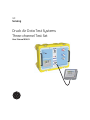
Three-channel Test Set
User Manual K0451
XX
© General Electric Company. All rights reserved.
i
Druck ADTS 2XX User Manual
Introduction
• This technical manual provides operating instructions for the Air Data Test System compatible with the
requirements of first line operation.
Scope
• This technical manual contains the description, identification data and operating procedures
for the user of this equipment.
Safety
• The manufacturer has designed this equipment to be safe when operated using the procedures detailed
in this manual. Do not use this equipment for any other purpose than that stated.
• This publication contains operating and safety instructions that must be followed to ensure safe
operation and to maintain the equipment in a safe condition. The safety instructions are either warnings
or cautions issued to protect the user and the equipment from injury or damage.
Use qualified* technicians and good engineering practice for all procedures in this publication.
Pressure
• Do not apply pressure greater than the maximum safe working pressure to the equipment.
Toxic Materials
• There are no known toxic materials used in this equipment.
Maintenance
• The equipment must be maintained using the manufacturer’s procedures and should be carried out by
authorized service agents or the manufacturer’s service departments.
Technical Advice
• For technical advice contact the manufacturer or subsidiary.
*
A qualified technician must have the necessary technical knowledge, documentation, special test
equipment and tools to carry out the required work on this equipment.
K0451 Issue No. 1
Druck ADTS 2XX User Manual
ii
This equipment meets the requirements of all relevant European safety directives. The
equipment carries the CE mark.
This symbol, on the instrument, indicates that the user should refer to the user manual. This
symbol, in this manual, indicates a hazardous operation.
Do not dispose of this product as household waste. Use an approved organisation that
collects and/or recycles waste electrical and electronic equipment. For more information,
contact one of these:
•
our customer service department (contact us at www.gesensing.com)
•
your local government office
Approved Service Agents
For a list of approved service agents, visit our website: www.gesensing.com
K0451 Issue No. 1
iii
Druck ADTS 2XX User Manual
TABLE OF CONTENTS
Preliminary pages
Introduction .......................................................................................................................................................................................................................... i
Scope
.......................................................................................................................................................................................................................... i
Approved Service Agents....................................................................................................................................................................................................ii
Table of contents (this table) ............................................................................................................................................................................................iii
Table of Illustrations.............................................................................................................................................................................................................iv
List of Tables ........................................................................................................................................................................................................................iv
ATEX Certified Advanced Hand Terminal ....................................................................................................................................................................v
Abbreviations ........................................................................................................................................................................................................................vi
Glossary
..................................................................................................................................................................................................................... viii
Pressure units and conversion factors.........................................................................................................................................................................x
Section
Title
page
1
2
INTRODUCTION AND DESCRIPTION
INSTALLATION
2.1
2.2
2.3
2.4
2.5
2.6
2.7
2.8
2.9
Packaging ................................................................................................................................................................................................................ 3
Packaging for Storage and Transportation .............................................................................................................................................. 3
Return Goods Procedure.................................................................................................................................................................................... 4
Electrical Connection........................................................................................................................................................................................... 5
Pneumatic Pressure Connection.................................................................................................................................................................... 6
Positioning of the ADTS 2XX ............................................................................................................................................................................. 7
Parts and Accessories......................................................................................................................................................................................... 8
Interconnection and Configuration ............................................................................................................................................................10
Software Programs Supplied on CD ...........................................................................................................................................................10
3
OPERATION
3.1
3.2
3.3
3.4
3.5
3.6
3.7
Preparation.............................................................................................................................................................................................................11
Power-up routine.................................................................................................................................................................................................12
Main Menu ..............................................................................................................................................................................................................13
Creating Custom Test Sequences for the ADTS 2XX ...........................................................................................................................22
Software Settings ................................................................................................................................................................................................25
SCPI Commands for the ADTS 2XX..............................................................................................................................................................27
Manual Venting of the Aircraft Pitot and Static Systems .................................................................................................................40
4
MAINTENANCE
4.1
4.2
4.3
4.4
Introduction............................................................................................................................................................................................................41
Materials and Tools ............................................................................................................................................................................................41
Maintenance Tasks.............................................................................................................................................................................................42
Routine Maintenance ........................................................................................................................................................................................43
5
TESTING AND FAULT FINDING
5.1
5.2
5.3
5.4
5.5
Standard Serviceability Test...........................................................................................................................................................................45
ADTS 2XX Leak Check........................................................................................................................................................................................46
Fault Diagnosis .....................................................................................................................................................................................................47
Error Messages.....................................................................................................................................................................................................47
Fault Finding ..........................................................................................................................................................................................................49
6
REFERENCE AND SPECIFICATION
6.1
6.2
6.3
General Specification ........................................................................................................................................................................................55
Air Data Specifications .....................................................................................................................................................................................56
Operating Limits...................................................................................................................................................................................................57
K0451 Issue No. 1
Druck ADTS 2XX User Manual
iv
TABLE OF ILLUSTRATIONS
Figure
1-1
1-2
2-1
2-2
2-3
2-4
3-1
3-2
3-3
3-4
3-5
3-6
5-1
5-2
Title
page
ADTS 2XX General Arrangement .................................................................................................................................................................... 1
ADTS 2XX General View...................................................................................................................................................................................... 2
ADTS 2XX Lid-mounted Expansion Connections .................................................................................................................................... 6
ADTS 2XX Altitude Correction ......................................................................................................................................................................... 7
ADTS 2XX Parts ....................................................................................................................................................................................................... 8
ADTS 2XX Interconnection...............................................................................................................................................................................10
Power-up Displays..............................................................................................................................................................................................12
Main Menu Screen ..............................................................................................................................................................................................13
Main Menu Selections .......................................................................................................................................................................................14
Manual Control Selections ..............................................................................................................................................................................15
Set-up Menu Selections....................................................................................................................................................................................18
Customer Test Sequence File Selections..................................................................................................................................................22
System Status.......................................................................................................................................................................................................48
Example Error Screen ........................................................................................................................................................................................49
LIST OF TABLES
Table
2-1
4-1
4-2
5-1
5-2
5-3
Title
page
Parts List .................................................................................................................................................................................................................... 9
Maintenance Chart.............................................................................................................................................................................................41
Materials List..........................................................................................................................................................................................................41
Error Messages.....................................................................................................................................................................................................50
Error Messages (continued) ............................................................................................................................................................................51
Error Messages (continued) ............................................................................................................................................................................52
K0451 Issue No. 1
v
Druck ADTS 2XX User Manual
ATEX CERTIFIED ADVANCED HAND TERMINAL
CONDITIONS OF USE
The ATEX certified Advanced Hand Terminal can be used in zone 2* hazardous areas in accordance with the
ATEX certification document and schedule.
Marking detail:
Refer to Advanced Hand Terminal User Manual K0418 and the label on the Advanced Hand Terminal.
SPECIAL CONDITION OF USE
•
The power supplies must be isolated when connecting the advanced hand terminal in the hazardous
area.
•
The advanced hand terminal must not be disconnected when energized in the hazardous area.
•
The advanced hand terminal is a non-serviceable component. If the advanced hand terminal
becomes unserviceable it can only be replaced by another ATEX compliant hand terminal.
Note:
The advanced hand terminal must only be used with the cable assembly supplied and marked “DO NOT
SEPARATE WHILST ENERGISED IN HAZARDOUS AREA”
* Zone 2 hazardous area definition, see page 53.
K0451 Issue No. 1
Druck ADTS 2XX User Manual
vi
Abbreviations
The following abbreviations are used in this manual; the abbreviations are the same in the singular and
plural.
A
abs
a.c.
ADTS
AHT
ALT
Alt1
Alt2
ARINC
ASI
ATE
CAS
COSHH
cm
d.c.
Def
e.g.
etc.
°C
°F
Fig.
ft
g
h
HBC
Hg
hm
Hz
IAS
i.e.
IEC
in
inHg
kg
km
kts
LCD
m
mA
max
mbar
min
mm
mph
mV
No.
PIN
Ps
Ps1
K0451 Issue No. 1
Ampere
Absolute
Alternating current
Air Data Test System
Advanced hand terminal
Altitude
Altitude static channel 1
Altitude static channel 2
Air Radio Incorporated
Airspeed indicator
Automatic Test Equipment
Calibrated airspeed
Control of Substances Hazardous to Health Regulations
Centimetre
Direct current
Define
For example
And so on
Degrees Celsius
Degrees Fahrenheit
Figure
Foot
Gauge
Hour
High breaking capacity
Mercury
Hecto metre
Hertz
Indicated airspeed
That is
International Electrotechnical Commission
Inch
Inches of mercury
Kilogram
Kilometre
Knots
Liquid crystal display
Metre
Milliampere
Maximum
Millibar
Minute or minimum
Millimetre
Miles per hour
Millivolts
Number
Personal identification number
Static pressure
Static channel 1
vii
Druck ADTS 2XX User Manual
Abbreviations (contd)
Ps
psi
PC
Pt
Qc
QFE
QNH
REF
RGA
RMS
ROC
RS232
Rt
RTC
SCPI
SST
ST
V
VA
+ve
-ve
Static channel 2
Pounds per square inch
Personnal computer
Total pressure (Pitot)
Differential pressure Ps1-Pt
Local atmospheric pressure
Barometric pressure at sea level
Reference
Return Goods Authorization (Druck procedure)
Root mean square
Rate of climb
Serial communications protocol
Rate
Real time clock
Standard commands for programmable instruments
Standard Serviceability Test
Stainless steel
Volts
Volt Ampere
Positive
Negative
K0451 Issue No. 1
Druck ADTS 2XX User Manual
viii
Glossary
Terminology
The terminology used in this manual is specific and individual interpretation must not be introduced. The
terms are defined as follows:
Adjust
To bring to a more satisfactory state; to manipulate controls, levers, linkages, etc. to return
equipment from an out-of-tolerance condition to an in-tolerance condition.
Align
To bring into line; to line up; to bring into precise adjustment, correct relative position or
coincidence.
Assemble:
To fit and secure together the several parts of; to make or form by combining parts.
Calibrate:
To determine accuracy, deviation or variation by special measurement or by comparison with
a standard.
Check:
Make a comparison of a measure of time, pressure, temperature, resistance, dimension or
other quality with a known figure for that measurement.
Disconnect: To detach the connection between; to separate keyed or matched equipment parts.
Dismantle:
To take apart to the level of the next smaller unit or down to all removable parts.
Examine:
To perform a critical visual observation or check for specific conditions; to test the condition of.
Fit:
Correctly attach one item to another.
Inspect:
Review the work carried out by Specialists to ensure it has been performed satisfactorily.
Install:
To perform operations necessary to properly fit an equipment unit into the next larger
assembly or system.
Maintain:
To hold or keep in any particular state or condition especially in a state of efficiency or validity.
Operate:
Make sure that an item or system functions correctly as far as possible without the use of test
equipment or reference to measurement.
Readjust:
To adjust again; to move back to a specified condition; to bring back to an in-tolerance
condition.
K0451 Issue No. 1
ix
Druck ADTS 2XX User Manual
Glossary (contd)
Reconnect:
To rejoin or refasten that which has been separated.
Refit:
Fit an item which has previously been removed.
Remove:
To perform operations necessary to take an equipment unit out of the next larger assembly or
system. To take off or eliminate. To take or move away.
Repair:
To restore damaged, worn out or malfunctioning equipment to a serviceable, usable or
operable condition.
Replace:
Remove an item and fit a new or a serviced item.
Reset:
To put back into a desired position, adjustment or condition.
Service:
To perform such operations as cleaning, lubricating and replenishing to prepare for use.
Test:
Ascertain by using the appropriate test equipment that a component or system functions
correctly.
K0451 Issue No. 1
Druck ADTS 2XX User Manual
x
Pressure Units and Conversion Factors
Pressure unit
Factor (Pascals)
Pressure unit
Factor (Pascals)
bar
100000
lbf/ft2
47.8803
lbf/in2 (psi)
6894.76
inHg
3386.39
mH2O
9806.65
inH2O [1]
249.089
mbar
100
ftH2O [1]
2989.07
kgf/cm2
98066.5
atm
101325.0
kgf/m2
9.80665
pdl/ft2
1.48816
mmHg
133.322
dyn/cm2
0.1
cmHg
1333.22
hbar
10000000
mHg
133322.0
tonf/ft2 (UK)
107252.0
mm/H2O [1]
9.80665
tonf/in2 (UK)
15444300
cm/H2O [1]
98.0665
inH2O (USA) [2]
248.64135
N/m2
1
ftH2O (USA) [2]
2983.6983
hPa
100
kp/mm2
9806650
kPa
1000
kp/cm2
98066.5
MPa
1000000
kp/m2
9.80665
torr
133.322
TABLE OF PRESSURE UNITS AND CONVERSION FACTORS
Unit Conversion
To convert FROM pressure VALUE 1 in pressure UNITS 1
TO pressure VALUE 2 in pressure UNITS 2, calculate as follows:
VALUE 2 = VALUE 1 x FACTOR 1
FACTOR 2
Note:
The conversion factor for pressure units referenced [1] are calculated for a water temperature of 4°C. Pressure
units referenced [2] are calculated for a water temperature of 68°F these units are normally used in the USA.
K0451 Issue No. 1
1
1
Druck ADTS 2XX User Manual
INTRODUCTION AND DESCRIPTION
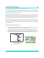
This three channel air data test system provides accurate air data to test a three port, pitot-static
Smart Probe ™ and other three-channel systems. To control the system, a touch screen on the
front panel enables the user, using a stylus (supplied), to send commands to each control channel
and to control test pressures either manually or from a stored test sequence. An advanced hand
terminal connected to the front panel can perform the same functions as the touch screen.
User-written test sequences, produced on a spreadsheet program can be uploaded from a pc to
the ADTS 2XX. Once stored in the system, the test sequence uses tables of pressure data to
simultaneously generate pressure aims for all three channels.
Smart Probe ™
The probe uses three pressure measurement channels identified as Ps1, Ps2 and Pt. The aircraft
air data computer system receives these three parameters and calculates altitude, airspeed and
angle of attack.
where:
Ps1 =
static pressure
Pt
=
pitot pressure
Ps2 =
static pressure
Ps1
=
altitude
Ps1 - Pt
=
Qc (airspeed)
Ps1 - Ps2
=
differential pressure, calculated with Qc, to produce angle of attack.
XX
Ps1
Pt
Ps2
FIGURE 1-1 ADTS 2XX GENERAL ARRANGEMENT
K0451 Issue No. 1
Druck ADTS 2XX User Manual
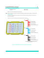
2
Power supply
connector
Static 1 (Ps1)
channel
connector
Power supply
switch
Power supply
indicator
Pitot (Pt)
channel
connector
Static 2 (Ps2)
channel
connector
Touch screen
and display
Hand terminal
connector
Earth/ground
connection stud
Water filter
drain vent
Calibration
enable switch
Do not obstruct
this vent
FIGURE 1-2 ADTS 2XX GENERAL V IEW
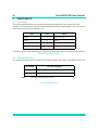
Operating Environment
K0451 Issue No. 1
Usage
Indoor and outdoor
Altitude range
-1500ft to 7500ft
Temperature range
0°C to 50°C
Humidity range
0 to 95% non-condensing
Rated pollution degree
II
3
2
Druck ADTS 2XX User Manual
INSTALLATION
2.1
Packaging
• On receipt of the ADTS 2XX check the contents of the packaging against the following lists:
SPECIAL REQUEST
Please keep the special packing box so that the ADTS 2XX can be safely shipped for calibration or repair.
Packaging List - ADTS 2XX
i)
Air Data Test System ADTS 2XX
ii)
Power supply cable 5m
iii)
Accessory bag
a)
Hose, 1m, blue, AN4 - AN4
b)
Hose, 1m, red, AN6 - AN6
c)
Hose, 1m, black, AN6 - AN6
d)
Cable, communications
e)
Spare fuses (4 off)
f)
O-ring 5 i/d x 1 (20 off)
g)
O-ring 8 i/d x 1 (20 off)
h)
User Manual (this publication), Calibration Manual K0425 and Quick Reference Guide
K0448
iv)
Advanced Hand Terminal
a)
CD containing file transfer and sample scripts
b)
Power supply adaptor and cables
c)
Cable external communications
d)
AHT User Manual K0418
2.2
Packing for Storage or Transportation
To store the tester or to return the tester for calibration or repair carry out the following procedures:
1.
Pack the tester as detailed in the following procedure.
2.
To return the tester for calibration or repair complete the return goods procedure.
Procedure
•
•
•
•
The tester should be at zero/ambient pressure. Disconnect the hose assemblies and stow in
the accessory bag.
Switch OFF and disconnect from the electrical power supply.
Close and latch the lid to the tester.
The power supply cable, should be placed in the original packing material.
• Place the tester in the original special packing box or appropriate transport container.
• Mark carton “FRAGILE” on all sides, top, and bottom of the container.
• To return the tester for calibration or repair complete the return goods procedure as detailed in 2.3.
K0451 Issue No. 1
Druck ADTS 2XX User Manual
4
Environment
• The following conditions apply for both shipping and storage:
•
•
•
Store in a cool dry place.
Temperature Range
-20 to +70 °C (-4 to +158 °F)
Altitude
up to 15,000 feet (4,570 metres)
Should the tester become exposed to moisture or very high humidity, dry as soon as possible and
temporarily store in a dehumidified area. The ADTS 2XX Test Set has one-year re-certification
requirement.
Note: It is important that the customer be sure the tester is in compliance with the OEM re-certification.
2.3
Returned Goods Procedure
• Should the unit require calibration or become unserviceable it can be returned to the Druck Service
Department.
• Please contact our Service Department, either by 'phone, fax or E-mail, to obtain a Returned Goods
Authorization (RGA) number or (Return Material Authorization [RMA] in USA), providing the following
information:
Product (i.e. ADTS 2XX)
Serial number
Details of defect/work to be undertaken
Calibration traceability requirements
Operating conditions
SAFETY PRECAUTIONS
• You must also tell us if the product has been in contact with anything hazardous or toxic and, the
relevant COSHH (MSDS in USA) references and precautions to be taken when handling.
IMPORTANT NOTICE
Service or calibration by unauthorized sources will affect the warranty and may not guarantee
further performance.
K0451 Issue No. 1
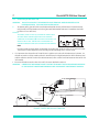
5
2.4
Druck ADTS 2XX User Manual
Electrical Connection
WARNINGS:
1
2
VOLTAGES IN EXCESS OF 30 VOLTS (RMS) AC OR 50 VOLTS DC, IN
CERTAIN CIRCUMSTANCES, CAN BE LETHAL. CARE MUST BE
TAKEN WHEN WORKING ON LIVE, EXPOSED CONDUCTORS.
DO NOT DISCONNECT THE ADVANCED HAND TERMINAL WHEN
ENERGIZED IN THE HAZARDOUS AREA.
USE IN A HAZARDOUS AREA
SPECIAL CONDITIONS APPLY TO THE ATEX CERTIFIED ADVANCED HAND TERMINAL REFER TO PAGE V.
Power Supply
Single phase, 90 to 132 VAC, 47 to 400Hz, 200 VA.
180 to 260 VAC, 47 to 66Hz, 300 VA.
Power Supply Connection
The unit must be connected to the correct electrical power supply as stated, adjacent to the
power connector.
A qualified technician (see page i) must carry out the following procedure.
CAUTIONS:
1
THE SUPPLY MUST PROVIDE CONNECTION TO A PROTECTIVE GROUND TERMINAL. THE UNIT MUST , AT ALL
TIMES, BE CONNECTED TO THE SUPPLY EARTH (GROUND).
2
THE POWER SUPPLY CABLE AND CONNECTOR MUST BE CORRECTLY RATED FOR THE POWER SUPPLY.
EUROPEAN
COLOUR
U.S.
COLOR
FUNCTION
Brown
Black
Live
Blue
White
Neutral
Green/Yellow
Green
Protective Earth
(Ground)
• Make sure that the power supply is off before connecting the power cable.
Fuses
The two fuses, located in the holders and mounted on the front panel, protect the unit. The fuses
are connected in the live and neutral supply circuit and are rated at:
5A anti-surge HBC 250V
z
z
External earth/ground connection
An external earth (ground) cable may be connected to the stud on the front panel of the unit
providing integrity of the earth (ground) connection.
Advanced Hand Terminal Power Pack (Figure 2-3)
Four interchangeable adaptors, supplied with the power pack, can be used to connect to the local
power supply. To change the power pin adaptor, push the adaptor from the power pack body,
align the replacement adaptor and push into the power pack body.
K0451 Issue No. 1
Druck ADTS 2XX User Manual
2.5
6
Pneumatic Pressure Connections
Ps1 and Ps2 (static)
Pt (pitot)
-
AN6 37° flare
AN4 37° flare
When not in use, a blanking cap must be fitted.
Note: When carrying out a leak test, a leak of this blanking cap affects the performance of the ADTS 2XX.
z
Expansion ports
Four sets of five expansion ports locate in the lid of the test set to provide hose connections for
pitot-static adaptors.
z
When not in use, a blanking cap must be fitted to each connector.
Exp1
Ps1
S1 system (left)
S1 system (right)
Ps1 smart probe
not used - fit blanking cap
Exp2
Pt
P1 system (left)
P1 system (right)
Pt smart probe
not used - fit blanking cap
Exp3
Ps2
S2 system (left)
S2 system (right)
Ps2 smart probe
not used - fit blanking cap
Example Using Lid-mounted Expansion
Connection Ports
FIGURE 2-1 ADTS 2XX LID-MOUNTED EXPANSION CONNECTIONS
K0451 Issue No. 1
7
2.6
Druck ADTS 2XX User Manual
Positioning of the ADTS 2XX
WARNING:
DO NOT DISCONNECT THE ADVANCED HAND TERMINAL WHEN ENERGIZED IN THE
HAZARDOUS AREA. THIS CAN CAUSE AN EXPLOSION.
z
To operate safely, the ADTS 2XX must be placed outside the user defined zone 2 hazardous area.
Only the ATEX certified hand terminal may be used inside the defined zone 2 hazardous area (refer
to section 5 for a definition).
CAUTION:
TO OPERATE, PLACE THE UNIT ON A HORIZONTAL SURFACE WITH
B
THE FRONT PANEL UPPERMOST (A) OR WITH THE PNEUMATIC
A
CONNECTOR PS1 UPPERMOST (B) THIS ALLOWS THE WATER IN THE
WATER FILTER TO VENT . WATER COULD CONTAMINATE THE
ref
CONTROLLER MANIFOLD AND AFFECT CONTROLLER PERFORMANCE.
vent
ref
Note:
In control mode, the water drain, located near the cooling vent, produces a flow of air and some water.
The amount of water depends on the humidity and the operating time in control mode.
• It is important that the position of the ADTS 2XX in relation to the aircraft altitude sensors is known. An
altitude correction must be made to allow for the difference in height between the ADTS reference level
and the reference level of the aircraft's altitude sensors (refer to the Aircraft Maintenance Manual for this
information).
• Enter the altitude correction value in the SET-UP menu detailed in section 3.
WARNING:
OBSERVE THE APPROPRIATE SAFETY INSTRUCTIONS AND TESTING PROCEDURES DETAILED
IN THE AIRCRAFT MAINTENANCE MANUALS AND COMPONENT MAINTENANCE MANUALS.
inst
reference level
AIR DATA
COMPUTER
positive
altitude
correction
value
reference level
FIGURE 2-2 ADTS 2XX ALTITUDE CORRECTION
K0451 Issue No. 1
Druck ADTS 2XX User Manual
2.7
8
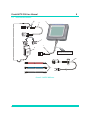
Parts and Accessories
³
3
5
7
1
6
191-
³
DO NOT SEPARATE WHILST
ENERGISED IN HAZARDOUS AREA
198
2C
4
FIGURE 2-3 ADTS 2XX PARTS
K0451 Issue No. 1
9
Druck ADTS 2XX User Manual
Description
Part Number
No.
Qty per
assy
1
ADTS204-3435-01-M2
Cable, Communications, 18m
1
2A*
ADTS505-3124-41-M0
Cable, AC Power, 5m (115V US plug)
1
Alternative
2B*
ADTS505-3124-40-M0
Cable, AC Power, 5m (250V UK plug)
1
Alternative
2C
ADTS405-1891-28-M0
Cable, AC Power, 5m (250V EU plug)
1
3
ADTS204-3435-05-M2
Hand terminal, advanced
1
4
ADTS204-3435-09-M0
Hose kit, comprising:
Hose, red, ST/STN, AN6
1
Hose, blue, ST/ST, AN4
1
Hose, black, ST/ST, AN6
1
5
ADTS204-3435-06-M0
Cable, communications, PC
1
6
ADTS204-3435-07-M0
Power pack
1
7
-
8*
ADTS204-3435-10-M0
part of item 6
Adaptor, power supply,
pack (comprising: 4)
Stylus, pack (comprising: 3)
1
1
*not illustrated
TABLE 2-1 PARTS LIST
K0451 Issue No. 1
Druck ADTS 2XX User Manual
10
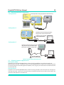
2.8 Interconnection and Configuration
Configuration 1
Normal operation using the Advanced Hand Terminal
REMOTE
HAND
TERMINAL
OPERATING
XX
or
(see set-up to change)
Configuration 2
XX
Uploading and downloading operations
using the PC communications cable
!
POWER PACK NOT REQUIRED
IN THIS CONFIGURATION
Configuration 3
Uploading and downloading operations
using the PC communications cable,
power pack and power supply cable
191-19
8
!
USE THE POWER PACK
IN THIS CONFIGURATION
FIGURE 2-4 ADTS 2XX INTERCONNECTION
2.9 Software Programs supplied on CD
File Transfer Utility
Installed on a PC with Windows® 98/2000 or above this utility establishes communications with the
Advanced Hand Terminal. It enables the user to use Windows® Explorer to copy files to the Advanced Hand
Terminal and perform file handling operations (delete, move, copy etc.) on files stored on the Advanced Hand
Terminal hard disk.
ADTS 2XX Remote
Installed on a PC with Windows® 98/2000 or above this utility provides a trial environment (or simulator) for
checking test scripts. It performs in the same way as the Advanced Hand Terminal without the need for the
connection and operation of the ADTS 2XX.
K0451 Issue No. 1
11
3
Druck ADTS 2XX User Manual
OPERATION
3.1 Preparation
WARNINGS:
1
OBSERVE SAFETY PRECAUTIONS STATED IN LOCAL ORDERS AND
THE AIRCRAFT OR EQUIPMENT SERVICING PROCEDURES.
2
DO NOT DISCONNECT THE ADVANCED HAND TERMINAL WHEN
ENERGIZED IN THE HAZARDOUS AREA.
USE IN A HAZARDOUS AREA
SPECIAL CONDITIONS APPLY TO THE ATEX CERTIFIED ADVANCED HAND TERMINAL REFER TO PAGE V.
CAUTION:
{
Make sure the electrical and pneumatic connectors, electrical cables and pipes and positioning of the
ADTS 2XX comply with the instructions and requirements in Section 2 Installation.
CAUTION:
{
IT IS THE RESPONSIBILITY OF THE USER TO MAKE SURE THAT THE PNEUMATIC CONTROL RANGE LIMITS ARE
SET BELOW THE MAXIMUM OPERATING LIMITS OF THE EQUIPMENT UNDER TEST REFER TO PAGE 19.
DO NOT USE SHARP OBJECTS ON THE TOUCH SCREEN; USE THE STYLUS (SUPPLIED AND RECOMMENDED). A
SHARP OBJECT WILL PERMANENTLY DAMAGE THE TOUCH SCREEN, IT CANNOT BE REPAIRED.
Carry out the following before use:
If necessary, carry out the maintenance task detailed in Section 4.
{
Make sure the air data test system power supply switch on the front panel is set to OFF.
Connect the air data test system to the electrical supply, make sure the supply includes a
connection to a protective earth.
Inspect the pneumatic hoses for damage, ingress of dirt and moisture. Make sure the aircraft
adaptors are serviceable.
Make sure the air vents do not become obstructed.
Make sure that the power supply switch can be accessed at all times.
Connect, to the air data test system, the hoses necessary for the test procedures to be carried out:
STATIC outputs (Ps1 and Ps2), PITOT output (Pt). Fit the necessary adaptors for aircraft testing to the
hoses.
Note: When connected, take care not to kink or stand on the hoses.
{
{
Before use, the ADTS 2XX should be tested by carrying out a leak test.
1.
Fit blanks to all the adaptor test points.
2.
Carry out a leak test, detailed in Section 5.2, or the system leak test procedure.
3.
If necessary carry out an altitude correction, see Figure 2.2.
Read the whole procedure before starting the test process on an aircraft or component.
K0451 Issue No. 1
Druck ADTS 2XX User Manual
12
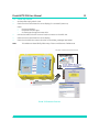
3-2 Power-up routine
{
Set the power supply switch to ON.
{
Check that the screen shows the correct display for a successful power-up.
Check:
{
the pump operates.
the power indicator lights
{
air discharges through the water drain.
Connect the cable to the AHT communication connector on the ADTS 2XX.
{
Check that the screen shows the correct display.
{
Check that the ADTS 2XX screens show the correct display messages (see below).
{
{
Note:
This Windows£ based facility hides many of the normal features of Windows£.
Front panel or advanced hand terminal screen
DRUCK ADTS 2XX
Three Channel
Air Data Test System
Main Menu Screen
FIGURE 3-1 POWER-UP DISPLAYS
K0451 Issue No. 1
13
Druck ADTS 2XX User Manual
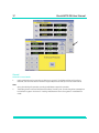
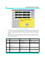
3-3 Main Menu
Selected
standard
function
Touch
screen
keys
Full Test Sequence - automatically starts and stops each test in turn (listed in the menu).
FIGURE 3-2 MAIN MENU SCREEN
Screen Displayed Key Selections
Touch screen keys (Figure 3-3)
Function and comments
UP/DOWN
Moves the screen highlight bar up/down.
Select
Selects the test or set of values highlighted by the up/down function.
Back
Returns to the previous screen.
Control
Leak Measure
Ground
Switches all channels between measure and control modes.
Restore Default Values
Restores the last set of stored data values or unit selection saved as a
default.
Save Settings
Data Values or unit selection saved as a default.
Select
Activates the highlighted function.
Exit Program
Exits Program - required for downloading of new test files.
Enter
Confirms data entry to a numeric field.
Starts the Go-to-Ground procedure for all channels.
K0451 Issue No. 1
Druck ADTS 2XX User Manual
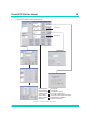
14
Select Customer Test Sequence
File Screen
System Set-up
Set-up menu selections
see Figure 3-5
Customer test sequence
file selections
see Figure 3-6
Manual Control Screen
Manual control selections
see Figure 3-4
FIGURE 3-3 MAIN MENU SELECTIONS
K0451 Issue No. 1
15
Druck ADTS 2XX User Manual
Manual Mode
FIGURE 3-4 MANUAL CONTROL SELECTIONS
Selecting Control and Leak/Measure Modes
Manual test control always starts in leak measure mode displaying pressures in the last selected units of
measurement. The system can be switched between aero units and pressure units, these units can only be
changed in set-up mode.
Selecting control/leak measure switches between leak measure mode and control mode. In control mode the
set of limits provide protection for the aircraft system and can only be changed in set-up mode.
K0451 Issue No. 1
Druck ADTS 2XX User Manual
Ps1, Ps2 and Pt
readings/results
16
Wait time
Measure
time
EXAMPLE RATE T IMER SCREEN
Rate Timer
Selected in Leak/Measure Mode
1.
Use the touch screen keys to select wait and measure times and use the numeric keys to enter the
values.
Note:
Times entered as whole numbers are interpreted as seconds. Numbers higher than 60 are interpreted
and displayed as minutes and seconds (i.e. 90 = 1 minute 30 seconds = 1:30).
2.
After selecting the timer values and with the required the Ps1, Ps2 and Pt readings, press the START
key. The time counter shows the progress of the test: wait time, then test time. The results, at the end
of the test, shows the timed rates for each channel indicated by “T” after the digits.
3.
Press BACK to return to Leak Measure Mode.
K0451 Issue No. 1
17
Druck ADTS 2XX User Manual
Ground
Selected in Control Mode
1.
Use the GROUND touch screen key to select go-to-ground. The displayed channel aims show
GROUND, the controller takes all channels to ground pressures and Qc to zero as shown above.
Note:
At any time during this operation, pressing Leak/Measure stops the operation.
2.
The display shows At Ground Pressures (see above). Pressing “OK” cancels the yellow message box
but leaves the system “At Ground”. Pressing Leak/Measure returns the system to Leak/Measure
mode.
K0451 Issue No. 1
Druck ADTS 2XX User Manual
18
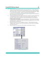
Select Set-up
1.
From the main menu, select system set-up.
see page 20
see page 20
Terminal Monitor
RS232 Settings
Calibrate Sensors
Calibrate Valves
Service Data
System Status
Restore Defaults
Main Menu
see page 20
see page 20
see Calibration Manual
see section 4 Maintenance
see section 5 Testing and Fault Finding
see section 5 Testing and Fault Finding
Restores factory set defaults
Returns to Main Menu
FIGURE 3-5 SET-UP MENU SELECTIONS
K0451 Issue No. 1
19
Druck ADTS 2XX User Manual
2.
Select Ps1 to Ps2 differential pressure limit and, using the numeric keys, enter the necessary value for
the testing to be carried out.
3.
Use the Up and Down keys to highlight the required aeronautical and pressure units.
4.
Press SAVE SETTINGS to store in nonvolatile memory or press MAIN MENU to store in volatile memory
and return to the Main Menu Screen. Press RESTORE DEFAULTS to restore the last set of stored values
and unit selection saved as a default.
Default limits
This first set of user defined limits, identified as:
USER 1, are enabled when the ADTS 2XX is
switched on. Refer to Section 6 for the details of
the preset limits.
Select limits
Enter the PIN to access the SETUP LIMITS
display. Select one of the preset limits of MAX,
STANDARD and CIVIL or define and enable USER
1 limits. An eight character name/code can
replace USER 2 title.
K0451 Issue No. 1
Druck ADTS 2XX User Manual
20
Altitude Correction
An altitude correction must be made to allow for the
difference in height between the reference level of the
ADTS 2XX and the reference level of the aircraft’s
altitude sensors. Select the Instrument Altitude
Correction and, using the numeric keys, enter the
correction value (see Fig 2-2).
RS232 Settings
The RS232 interface enables the unit to communicate
with a PC. The parameters for RS232
communications are applied through the set-up
menu.
Baud rate
600, 1200, 2400, 9600
Data bits
8
Stop bits
1,2
Parity
none, even, odd
Auto leak
Auto leak automatically regains control if the leak rate becomes too high for any of the control channels. Auto
leak operates at preset rates of 3000ft/min and 300knots/min. This facility can be switched off and on in setup menu.
Pressure Monitor
Set-up selection can be made between the display
showing the “REMOTE HAND TERMINAL OPERATING”
and the pressure monitor screen. The pressure monitor
shows the current pressures of all three channels in the
selected units of pressure measurement.
K0451 Issue No. 1
21
Druck ADTS 2XX User Manual
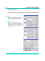
Select Test Sequence File
Files stored in the computer
1.
From the main menu, select Custom Test
Sequence File.
2.
Use the Up and Down keys to highlight the test
file.
3.
Use the SELECT key to load the file.
4.
Press MAIN MENU to return to the Main Menu
Screen.
Title
Actual
channel
readings
Test
procedure
step
Measure/
Control
Actual rate of
pressure
Set of aim
values to be
used in control
mode
Only available
in Control Mode
changes to Rate Timer
in Leak/Measure Mode
Rate aim to be
used in this TP
step.
Selecting a Test Sequence
1.
From the main menu, select the Custom Test Sequence File. The screen changes to the selected test
screen with the data table from the file.
2.
Use the touch screen keys to select each test procedure value.
3.
After selecting the test procedure value use the Control/Leak Measure key to select CONTROL.
4.
The screen changes to CONTROL MODE and shows the actual measurement and rate.
K0451 Issue No. 1
Druck ADTS 2XX User Manual
22
3-4 Creating Custom Test Sequences for the ADTS 2XX
Instructions for generating or editing source data for test table values
The data shown on each screen or table of the test sequence comes from a single data source file. This .CSV
format file uses numeric data fields separated by commas. Files of this type may be viewed and edited using
a spread sheet program such as Excel. Files would normally be saved with an applicable name for easy
identification and selection.
A template file (TEMPLATE.CSV), provided on the software distribution with this product, may be used as the
basis for creating new aircraft test sequences. An example, below, shows how the data fields of the file can
be used in the test screens.
Rate Units
Test Table Title
Header 2
Header 1
Ref
Aim Units
Test Descriptor
Ps1, Ps2, Pt Aims
Ps1, Ps2, Pt Rates
Message
FIGURE 3-6 CUSTOMER TEST SEQUENCE FILE SELECTIONS
K0451 Issue No. 1
<TEST DESCRIPTOR (d)> <MESSAGE (d)>
<TEST DESCRIPTOR (e)> <MESSAGE (e)>
<REF (c)>
<REF (d)>
<REF (e)>
<TEST DESCRIPTOR (e)> <MESSAGE (e)>
<REF (d)>
<REF (e)>
<RATE UNIT>
Ps1 Rate
<RATE UNIT>
Ps2 Rate
<RATE UNIT>
Pt Rate
<Pt Aim (a)> <Ps1 Rate (a)> <Ps2 Rate (a)> <Pt Rate (a)>
<AIM UNIT>
Pt Aim
<Ps2 Aim (c)>
<Pt Aim (c)> <Ps1 Rate (c)> <Ps2 Rate (c)> <Pt Rate (c)>
<Ps2 Aim (a)>
<AIM UNIT>
<Ps2 Aim (e)>
<RATE UNIT>
<RATE UNIT>
<RATE UNIT>
<Pt Rate (e)>
<Pt Aim (a)> <Ps1 Rate (a)> <Ps2 Rate (a)> <Pt Rate (a)>
<AIM UNIT>
<Pt Aim (e)> <Ps1 Rate (e)> <Ps2Rate (e)>
<Ps2 Aim (c)>
<Pt Aim (c)> <Ps1 Rate (c)> <Ps2 Rate (c)> <Pt Rate (c)>
<Ps1 Aim (e)>
<Ps2 Aim (e)>
<Pt Aim (e)> <Ps1 Rate (e)> <Ps2Rate (e)>
<Pt Rate (e)>
<Ps1 Aim (d)> <Ps2 Aim (d)> <Pt Aim (d)> <Ps1 Rate (d)> <Ps2 Rate (d)> <Pt Rate (d)>
<Ps1 Aim (c)>
<Ps1 Aim (b)> <Ps2 Aim (b)> <Pt Aim (b)> <Ps1 Rate (b)> <Ps2 Rate (b)> <Pt Rate (b)>
<Ps1 Aim (a)>
<AIM UNIT>
<Ps1 Aim (e)>
<Ps1 Aim (d)> <Ps2 Aim (d)> <Pt Aim (d)> <Ps1 Rate (d)> <Ps2 Rate (d)> <Pt Rate (d)>
<Ps1 Aim (c)>
Control keywords - delimits the start of a test table data set.
Control keywords - delimits the end of a test table data set.
Free text field (34 characters maximum) - title for a page of test aims.
Free text field column title (3 characters maximum).
Free text field (29 characters maximum) - describes test.
Control field - sets the units for entry of channel pressure aims, pressure or aeronautical, as per the units screen.
Control field - sets the units for entry of channel pressure rates, pressure or aeronautical, as per the units screen.
Free text field per test row (3 characters maximum) - refers to a section of a test document etc.
Free text field per test row (29 characters maximum) - describes test conditions at that point etc.
Free text field per test row (70 characters maximum) - gives instructions to the user etc.
Numeric entry fields (3 per test row) - must contain a pressure aim for each channel in units <AIM UNIT>.
Numeric entry fields (3 per test row) - must contain a pressure rate for each channel in units <RATE UNIT>.
<TEST DESCRIPTOR (d)> <MESSAGE (d)>
<REF (c)>
<Ps2 Aim (a)>
<AIM UNIT>
Ps2 Aim
<Ps1 Aim (b)> <Ps2 Aim (b)> <Pt Aim (b)> <Ps1 Rate (b)> <Ps2 Rate (b)> <Pt Rate (b)>
<Ps1 Aim (a)>
<AIM UNIT>
Ps1 Aim
Note: The example template file (.XLS, format, with coloured fields as above) may be used for creation, edit or archive of new test sequence
files. A copy of the data sheet MUST be saved in .CSV file format for direct use by the ADTS 2XXuser interface program (.CSV files do not use
the colour and column width of the .XLS).
Begin Test Table End Test Table <TEST TABLE TITLE n><HEADER 1>
<HEADER 2>
<AIM UNIT>
<RATE UNIT>
<REF (a) to (e)> <TEST DESCRIPTOR (a)>
<MESSAGE (a)> <P[s1]Aim(a) to (e)><P[s1]Rate(a) to (e)>-
Field Descriptions
End Test Table
<TEST DESCRIPTOR (b)> <MESSAGE (b)>
<TEST DESCRIPTOR (c)> <MESSAGE (c)>
<REF (b)>
<TEST DESCRIPTOR (a)> <MESSAGE (a)>
<REF (a)>
<HEADER 2>
<TEST DESCRIPTOR (b)> <MESSAGE (b)>
<TEST DESCRIPTOR (c)> <MESSAGE (c)>
<REF (b)>
<HEADER 2>
<TEST DESCRIPTOR (a)> <MESSAGE (a)>
Prompt Message
<REF (a)>
Parameter Label
<HEADER 1>
Test Identifier
<TEST TABLE TITLE 2> <HEADER 1>
Begin Test Table
End Test Table
<TEST TABLE TITLE 1>
Begin Test Table
(files to be created using EXCEL and saved as <FILENAME.CSV> (comma separated variables)
TEMPLATE FORMAT DESCRIPTION FOR CREATION OF ADTS 2XX TEST SEQUENCE FILES
23
Druck ADTS 2XX User Manual
K0451 Issue No. 1
Druck ADTS 2XX User Manual
24
Transferring <NEW AIRCRAFT.CSV> files from a PC to:
the ADTS 2XX Advanced Hand Terminal or ADTS 2XX
New .csv file test scripts can be tested for general syntax and screen formatting using the desktop PC utility
“ADTS 2XX Remote” (DK250). This utility requires no external equipment connections to operate, available for
installation from the distributor.
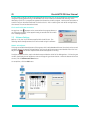
Transferring Files using GE FileTransfer Utility
CAUTION:
DO NOT CONNECT THE POWER PACK (Table 2-1, item 6) TO THE PC COMMUNICATIONS CABLE (Table 2-1, item
5) WHEN IT IS CONNECTED BETWEEN THE ADTS 2XX AND PC.
Connect the PC communications cable (Table 2-1, item 5)
into an available 9-way ‘D‘ COM port on the PC and the
connector of the Advanced Hand Terminal.
Use the icon on the windows CE desk top to start the File
Transfer Utility.
To start the File Transfer Utility on the PC, double click the
icon, set the File Transfer Utility, click the + to
expand the Advanced Hand Terminal drive as shown:
+
Notes:
1. Check which serial communications has been connected,
use the RS232 drop-down menu to set the PC
communications port (COM1 to COM 4). The system stores
this setting and automatically selects this port on the next
power-up.
2. Only files directly loaded to the AHT will be accessible in the
AHT menus. To be accessible from the ADTS 2XX the files
must be also loaded in the ADTS 2XX. This requires a
different connection configuration see Figure 2-4.
K0451 Issue No. 1
25
Druck ADTS 2XX User Manual
To copy a new script file (.csv file) to the Advanced Hand Terminal click-on and highlight the required file and,
using the File/Copy/Paste facility in Windows®, click on the Hand terminal/Hard Disk directory as the
destination of the file. A progress bar appears and shows the transfer progress. Use the same procedure to
transfer files from the Advanced Hand Terminal to the PC. After re-starting the main ADTS 2XX application,
the new test file can be selected and used.
File Transfer Utility NO Connection
An egg-timer icon
appears on the screen when the program detects a
no connection condition. After approximately 20 seconds this file transfer
error message appears.
3.5
Software Settings
Refer to 2.7 for the list of software supplied with the ADTS 2XX. The
following details the adjustments that can be made using this software
DK285 – RTC Adjuster
This program enables the adjustment of the system clock in Windows® and the real-time clock on the control
computer board. To execute this application, exit from the ADTS 2XX program and double click on the icon
Adjust Clock
. The screen capture below shows the application running.
To adjust the date and time, use the window boxes provided on the left of the dialogue box. Click on the year
number, the display shows up/down arrows to change the year shown below. When the date and time are
correct, click the Set Date And Time button.
On completion, click the Exit button.
K0451 Issue No. 1
Druck ADTS 2XX User Manual
26
DK286 – Touch Screen Calibrator
This program enables the calibration of the touch screen. To execute this application, exit from the ADTS 2XX
program and double click on the Calibrate Touch icon
. The Stylus application, stored as part of the
system application, executes first. Select the calibration option and click the Recalibrate button. Follow the
on-screen instructions, after obtaining all the calibration points, touch the screen once and the Stylus
program returns to the previous screen. Close down the Stylus application, the screen shows the following:
This screen gives the opportunity to save the calibration by clicking the Save Screen Calibration button, or
restoring the default screen calibration stored by clicking the Restore Default Calibration Data button. The
system stores the calibration data.
On completion, click the Exit button.
DK287 – Display Backlight Brightness Setting Program
This program enables the user to adjust the brightness of the display backlight. To execute this program, exit
the ADTS205 program and double click on the icon Set BkLight Brightness
. The screen shows the
following:
The slide bar Brightness Level starts in the position of the current backlight brightness. Adjust the brightness
level by moving the slide bar left for darker and right for brighter. The backlight changes as the slide bar
moves. To save the setting, click the Save Brightness Setting button, this stores the current brightness
setting.
On completion, click the Exit button.
K0451 Issue No. 1
27
3.6
Druck ADTS 2XX User Manual
SCPI Commands for the ADTS 2XX
Through the RS232 serial interface the ADTS 2XX can be remotely controlled from a PC. The ADTS 2XX receives
commands and queries, it responds by changing operating modes and conditions and by sending
information on status and pressure readings. The communications parameters for the RS232 interface can
be configured in the set-up menu and are based on typical SCPI syntax. The PC communications cable (item
5, Table 2-1) should be used for connection between the PC and the ADTS 2XX (see Figure 2-4).
External Control using RS232 Communications
SCPI Commands
This section describes each command and query in detail including parameters used and response data
returned. The general short form command is shown at the top of each page. The following information
given:
Command Syntax
Parameter Type
Parameter Range
-
Units
Password
Function
-
Conditions
-
Query Syntax
-
Parameter Type
Parameter Range
Returned Data
Returned Data Type
Returned Data Range
Units
Function
Conditions
-
The upper case represents the short form command.
REAL, INTEGER, DISCRETE or STRING
Either the range of INTEGER/REAL numbers or the choice of DISCRETE or
maximum STRING length.
The units used for some specified parameters.
Password protects some commands; software version 4.30 onwards.
Basic function of the command, see user manual for full description of the
function.
Any condition that limits the use of a command.
Syntax of query command includes parameters passed as part of the
query.
As for command (above).
As for command (above).
Data returned by the ADTS following a query command.
As parameter type.
As parameter range.
Units of returned data.
Basic function of query command.
As for command.
Commands to ADTS 205
All SCPI commands must be terminated with 0A Hex
Command Responses from ADTS 2XX
All responses from the ADTS 2XX terminate with 0A Hex.
K0451 Issue No. 1
Druck ADTS 2XX User Manual
28
MEAS
This group of query commands returns the measured values.
MEAS:PRES
Command Syntax
N/A
Parameter Type:
Parameter Range:
Function:
Conditions:
Query Syntax
MEASure:PRESsure? <parameter>
Parameter Type:
Parameter Range:
Returned Data Static Channels:
Returned Data Pitot Channel:
DISCRETE
ALT | CAS | MACH | PS | PT | QC
<value>,<value>
<value>,*
Function:
Conditions:
To query measured pressure.
None
K0451 Issue No. 1
29
Druck ADTS 2XX User Manual
MEAS:RATE
Command Syntax
N/A
Parameter Type:
Parameter Range:
Function:
Conditions:
Query Syntax
MEASure:RATE? <parameter>
Parameter Type:
Parameter Range:
Returned Data Static Channels:
Returned Data Pitot Channel:
DISCRETE
ALT | CAS | PS | PT | QC
<value>,<value>
<value>,*
Function:
To query measured instant rate of change for specified parameter.
Conditions:
Rate timer must not be operating.
K0451 Issue No. 1
Druck ADTS 2XX User Manual
30
STAT
This group of commands monitor and control the status bytes that show the status of the ADTS 2XX.
STAT:OPER:CON
Command Syntax
N/A
Parameter Type:
Parameter Range:
Function:
Conditions:
Query Syntax
STATus:OPERation:CONdition?
Parameter Type:
Parameter Range:
Returned Data:
Returned Data Type:
Returned Data Range:
None
<status>
INTEGER
0-32767
Function:
To query the status of the ADTS. The table shows the function of each bit.
Conditions:
None
Bit
0
1
2
3
4
5
6
7
8
9
10
11
12
13
14
15
K0451 Issue No. 1
Data
Reserved – returns 0
Ps1 controlling and at set-point
At ground
Ps2 controlling and at set-point
Pt controlling and at set-point
Reserved – returns 0
Reserved – returns 0
Reserved – returns 0
Reserved – returns 0
Reserved – returns 0
Reserved – returns 0
Reserved – returns 0
Reserved – returns 0
Reserved – returns 0
Reserved – returns 0
Reserved – returns 0
31
Druck ADTS 2XX User Manual
SOUR
This group of commands control the controller states, aim and limit values.
SOUR:GTGR
Command Syntax
SOURce:GTGRound
Parameter Type:
Parameter Range:
Function:
Conditions:
None
To return the ADTS 2XX to ground pressure.
Rates to be set first.
Must be in control mode.
Query Syntax
SOURce:GTGRound?
Parameter Type:
Parameter Range:
Returned Data Static Channels:
Returned Data Pitot Channel:
Returned Data Type:
Returned Data Range:
None
<state>,<state>
<state>
Boolean
0|1
Function:
Returns:
1 - only when the ADTS 2XX is safe at ground
0 - for all other conditions
Conditions:
None
K0451 Issue No. 1
Druck ADTS 2XX User Manual
32
SOUR:PRES
Command Syntax
SOURce:PRESsure <parameter>, <aim>, <aim>
Parameter Type:
DISCRETE, REAL
Parameter Range:
ALT | CAS | MACH | PS | PT | QC
Static Channels:
SOUR:PRES <parameter>,<Ps1 Aim>,<Ps2 Aim>
Pitot Channel:
SOUR:PRES <parameter>,<Pt Aim>
Function:
To command the selected parameter to a new aim value.
Conditions:
Controllers must be ON before using this command.
Query Syntax
SOURce:PRESsure? <parameter>
Parameter Type:
DISCRETE
Parameter Range:
ALT | CAS | MACH | PS | PT | QC
Units:
As set UNIT command
Returned Static Channels:
<Ps1 Aim>,<Ps2 Aim>
Returned Pitot Channel:
<Pt Aim>, *
Function:
To query the last commanded aim values
Conditions:
See current limit settings
K0451 Issue No. 1
33
Druck ADTS 2XX User Manual
SOUR:RATE
Command Syntax
SOURce:RATE<parameter> <aim>
Parameter Type
DISCRETE, REAL
Static Channels:
SOUR:RATE <parameter>,<Ps1 Rate Aim>,<Ps2 Rate Aim>
Pitot Channel:
SOUR:RATE <parameter>,<Pt Rate Aim>
Parameter Range:
ALT | CAS | MACH | PS | PT | QC
Function:
To command the rate of change of the selected parameter to a new aim
value.
Conditions:
Must be in control mode.
Query Syntax
SOURce:RATE? <parameter>
Parameter Type
Parameter Range:
Returned Static Channels:
Returned Pitot Channel
DISCRETE
ALT | CAS | MACH | PS | PT | QC
<Ps1 Aim>,<Ps2 Aim>
<Pt Aim>, *
Function:
To query last rate command.
Conditions:
None.
K0451 Issue No. 1
Druck ADTS 2XX User Manual
34
SOUR:STAT
Command Syntax
SOURce:STATe <state>
Parameter Type
Parameter Range:
DISCRETE
CONTROL | MEASURE | ON | OFF
Function:
To change the mode of the pressure controllers.
CONTROL or ON to go to control mode.
MEASURE or OFF to go to measure mode.
Conditions:
Must be in control mode.
Query Syntax
SOURce:STATe?
Parameter Type
Parameter Range:
Returned Data:
Returned Data Type:
Returned Data Range:
<state>
DISCRETE
ON | OFF
Function:
To query state of pressure controllers.
Conditions:
None
K0451 Issue No. 1
None
35
Druck ADTS 2XX User Manual
SYST
This group of commands controls system functions such as data, time and errors.
SYST:ERR
Command Syntax
N/A
Parameter Type:
Parameter Range:
Function:
Conditions:
None
Query Syntax
SYSTem:ERRor?
Parameter Type:
Parameter Range:
Returned Data:
Returned Data Type:
Returned Data Range:
None
<err number>,<err text>
INTEGER, STRING
Function:
Returns oldest SCPI error and then deletes that error. Use the query
repeatedly to get all errors until 0, “No error” is returned.
Note; <err text> is returned in “double quotes”.
Conditions:
None
K0451 Issue No. 1
Druck ADTS 2XX User Manual
36
UNITS
This group of commands is used for setting the units of measurement.
UNITS:AER
Command Syntax
UNITS:AERonautical <units>
Parameter Type:
Parameter Range:
DISCRETE
FTKNTS | FTMPH | MKPH(M/S) | MKPH(M/MIN)
Function:
Sets the aeronautical units used for SCPI commands and queries.
Conditions:
None
Query Syntax
UNITS:AERonautical?
Parameter Type:
Parameter Range:
Returned Data
Returned Data Type:
Returned Data Range:
<units>
DISCRETE
FTKNTS | FTMPH | MKPH(M/S) | MKPH(M/MIN)
Function:
To query the SCPI aeronautical units.
Conditions:
None
K0451 Issue No. 1
None
37
Druck ADTS 2XX User Manual
UNITS:PRES
Command Syntax
UNITs:PRESsure <units>
Parameter Type:
Parameter Range:
Function:
Conditions:
DISCRETE
MBAR, INHG, PSI, MMHG, KPA, HPA
To set the pressure units used for SCPI commands and queries. The display
only shows these units when SOUR:PRES or SOUR:RATE is sent.
None
Query Syntax
UNITs:PRESsure?
Parameter Type:
Parameter Range:
Returned Data
Returned Data Type
Returned Data Range:
None
<units>
DISCRETE
MBAR, INHG, PSI, MMHG, KPA, HPA
Function:
To query the SCPI pressure units.
Conditions:
None
K0451 Issue No. 1
Druck ADTS 2XX User Manual
38
Standard Commands
The commands starting with * are standard SCPI commands.
*IDN
Command Syntax
N/A
Parameter Type
Parameter Range:
Function:
Conditions:
Query Syntax
*IDN?
Parameter Type:
Parameter Range:
Returned Data:
Returned Data Type:
Function:
None
DRUCK,ADTS Three Channel System V1.0.28 <Cal Date>
<Cal Date> is NO CALIBRATION DATE or [dd,mm,yyyy]
STRING
Conditions:
*GTL
Command Syntax
*GTL
Parameter Type
Parameter Range:
Function:
Conditions:
Query Syntax
N/A
Parameter Type:
Parameter Range:
Returned Data:
Returned Data Type:
Function:
Conditions:
K0451 Issue No. 1
Gets the ADTS out of Remote Mode.
39
Druck ADTS 2XX User Manual
*REM
Command Syntax
*REM
Parameter Type
Parameter Range:
Function:
Puts the ADTS into Remote Mode ready to receive SCPI Commands.
This is the first command the user must use before sending any other
commands.
Conditions:
None
Query Syntax
N/A
Parameter Type:
Parameter Range:
Returned Data:
Returned Data Type:
Function:
Conditions:
K0451 Issue No. 1
Druck ADTS 2XX User Manual
3.7
40
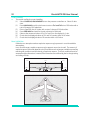
Manual Venting of the Aircraft Pitot and Static Systems
Instrument Status on Power Failure
On removal of power, the main output valve linking external ports Ps1, Ps2 and Pt to the internal pressure
controllers will automatically close. The aircraft pitot and static systems remain safe but with the last applied
pressures now isolated and maintained in the hoses.
Instrument Status on Restoration of Power
When power is restored to the instrument the normal self test routine for the controllers will be performed and
at the end of this the controller will exactly equalize the internal manifold pressures to match those of the
external aircraft hoses and then the output valves will be reopened. This process will at all times protect the
aircraft pitot and static systems from adverse pressure transients, differentials or excessive rates.
When the output valves are fully opened, the normal parameter measurement screens become available
from the main menu and full control is again available. The testing may then either continue from the same
point (when the power failure occurred) or the aircraft pitot and static systems may be safely controlled back
to ground pressures.
Actions if power cannot be quickly restored
Two courses of action are possible at this point:
1
Leave the ADTS 2XX connected to the aircraft pitot and static systems with pipes safely isolated but
maintaining trapped pressures until such time as power can be restored.
2
Use the manual let-down valves on the instrument front panel to safely bleed the trapped hose
pressures back to ambient ground. This must be carried out in a way that ensures the Ps1 to Pt and
Ps1 to Ps2 differential pressures remain at zero while the whole connected system is brought to
ground pressure. The order of valve opening should be A then B to equalize, then C to vent to ground.
Atmosphere
Ps1
C
B
Pt
XX
A
Ps2
Let-down valves are precision
multi-turn, operated by small
slotted adjusters
K0451 Issue No. 1
41
Druck ADTS 2XX User Manual
4
MAINTENANCE
4.1
Introduction
This section details the before-use tasks and the weekly inspection to be carried out by the
operator. The maintenance chart shows the maintenance tasks, the periodicity of each task and a
code referenced to the task detailed in 4.3.
Task
Code
Period
Inspect
A
Daily, before use
Inspect
B
Weekly
Test
C
Before use
Test
D
Daily, before use
* Periodicity may change depending on usage and environment, refer to the Engineering Authority.
TABLE 4-1 MAINTENANCE CHART
4.2
Materials and Tools
This section provides lists of the materials and tools required for the user to maintain the ADTS 2XX.
Item Number
Note:
Item name, Description
1
Cloth, Cotton, Lint-Free
2
Detergent, Mild Liquid
Equivalent substitutes can be used.
TABLE 4-2 MATERIALS LIST
K0451 Issue No. 1
Druck ADTS 2XX User Manual
4.3
42
Maintenance Tasks
A
B
C
D
Check that all the equipment is present; record any deficiencies. Visually inspect the
external of the ADTS 2XX, and its associated equipment, for obvious signs of damage,
dirt, and the ingress of moisture. If necessary, use mild liquid detergent (item 2, Table
4-2) and a lint-free cloth (item 1, Table 4-2) to clean the external surfaces.
Inspect the pressure outlet ports and expansion ports for ingress of dirt and moisture,
clean if necessary with a lint-free cloth.
Visually inspect the pneumatic output connectors for damage. Inspect the small o-ring
on each pneumatic output connector for cuts and any signs of wear; replace as
necessary. Visually inspect pneumatic hoses, electrical cables for cuts, splits and
damage; replace as necessary.
Check, by entering the system set-up, service data (figure 4-1 below) the unit and pump
operational hours. At 1000 hours (filters) and 3000 hours (pump) return the unit to the
servicing depot for maintenance.
Before use, power-up the unit as detailed in Section 3. Check the date of the last
calibration and, if necessary, refer to the manufacturer. Record any error messages
and refer to Section 5.
Daily and before use, carry out the SST and leak check detailed in Section 5.
FIGURE 4-1 SERVICE DATA
K0451 Issue No. 1
43
4.4
Druck ADTS 2XX User Manual
Routine Maintenance
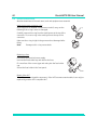
Absolute cleanliness of the work area, tools and equipment are essential.
Replacing the output connector o-ring
After inspection as detailed in maintenance task B, carry out the
following if the o-ring is worn or damaged:
o-ring
Carefully remove the o-ring from the small groove at the top of the
connector. Fit a new o-ring in the small groove at the top of the
connector.
Make sure the o-ring is tight in the groove and not damaged after
fitting.
Note:
Damage to this o-ring causes leaks.
Replacing a fuse
Disconnect the electrical power supply.
Unscrew the fuse holder cap and remove the fuse.
Fit a new fuse of the correct type and rating into the fuse holder
cap.
Secure the fuse holder in the front panel.
fuse
Repair of the AHT
The AHT is a non-serviceable component. If the AHT becomes unserviceable, it can only be
replaced by another ATEX compliant AHT.
K0451 Issue No. 1
Druck ADTS 2XX User Manual
INTENTIONALLY LEFT BLANK
K0451 Issue No. 1
44
45
5
Druck ADTS 2XX User Manual
TESTING AND FAULT FINDING
Limited fault finding and rectification can be carried out by the operator. Units can be returned
to the nearest GE Sensing Service Department (www.gesensing.com) for fault finding and
rectification.
Procedures
Any defect arising must be rectified before proceeding to the next operation.
Limits
The Control PC screen displays operational faults caused by leaks in the aircraft systems or
equipment. If the defined differential limit is exceeded the system goes to ground and the
screen displays the following message:
5.1
Standard Serviceability Test
|
The following procedure shows if the unit is serviceable and checks functions and facilities of
the ADTS 2XX. In this procedure:
Procedure
|
Connection and power-on checks.
Connect power to the unit.
Make sure the blanking caps are fitted to the Ps1, Ps2 and Pt front panel outputs.
Set the power supply switch to ON.
Check power indicator is on.
Check the display shows the first power-up message.
|
Check the display shows the system starting message.
|
The ADTS 2XX displays any detected errors, refer to fault finding.
Check that the display then changes to show the leak measure mode menu.
K0451 Issue No. 1
Druck ADTS 2XX User Manual
46
If necessary, select aero units and set aeronautical units of ft, kts and ft/min (see 3.3 to
change).
Press HOLD AIMS, to set the required parameters for Alt1, Alt2 and CAS.
Press CONTROL/LEAK MEASURE to go to control mode.
Set the Alt1 and Alt2 rate to 5000 ft/min.
Enter an altitude aim of 500 ft and an airspeed aim of 400 knots.
Press SENDS AIMS.
Check that these aim values are achieved, the rate of change are within the selected
rates and that the achieved aim values are stable.
Completion
|
Press GROUND, wait until the display shows `At Ground Pressures'. On successful completion
of this test procedure, switch off and disconnect the power supply.
5.2
ADTS 2XX Leak Check
|
Allow at least 15 minutes for the unit to warm-up.
Pressure leak check
|
This procedure verifies that the unit is leak tight under positive pressure conditions.
Select manual control from the main operation menu. Set the units of measurement to inHg.
Select RATE TIMER and set the WAIT time to 5min.00secs and the TIME to 1min.00secs.
2.
Press LEAK MEASURE/CONTROL to enter control mode. Press HOLD AIMS, to set the
required parameters Ps1, Ps2 and Qc. Enter a Ps aim of 31.00 inHg and a Qc aim of 8.00
inHg. Press SEND AIMS.
3.
Check that the system acheives the aim values.
4.
Press LEAK MEASURE/CONTROL to return to Leak Measure mode.
5.
Select RATE TIMER and press start. The display shows the waiting time counting down then
the timing countdown. Finally the display shows timed rates with a ‘T’ after each value.
6.
Check that the Ps1, Ps2 and Qc rates are less than or equal to ±0.015 inHg/min. If the rates
are greater than this value, allow further thermal stabilization time and re-test.
Vacuum leak check
1.
|
1.
2.
3.
4.
This procedure verifies that the unit is leak tight under vacuum conditions.
Press LEAK MEASURE/CONTROL to enter control mode. Press HOLD AIMS, to set the
required parameters Ps1, Ps2 and Qc. Enter a Ps aim of 25.00 inHg and a Qc aim of 0.00
inHg. Press SEND AIMS.
Check that the system acheives the aim values.
Press LEAK MEASURE/CONTROL to return to Leak Measure mode.
Select RATE TIMER and press start. The display shows the waiting time counting down then
the timing countdown. Finally the display shows timed rates with a ‘T’ after each value.
K0451 Issue No. 1
47
5.
6.
Druck ADTS 2XX User Manual
Check that the Ps1, Ps2 and Qc rates are less than or equal to ±0.015 inHg/min. If the rates
are greater than this value, allow further thermal stabilization time and re-test.
If a rate remains greater than the allowed value an internal leak is present. Return the unit
to the repair depot.
System status
|
To check the general condition of the controller system go to system set-up, system status
(Figure 5-1).
5.3
Fault Diagnosis
|
If the display shows a warning or error message, refer to the section below (Tables 5-1, 5-2
and 5-3).
|
If a controller is suspect refer to the controller stability check, page 53.
5.4
Error Messages
|
At power-up, the ADTS 2XX indicates if there is a fault by displaying an error code and message.
|
See paragaph 5.4 (Tables 5-1, 5-2 and 5-3) for the listings of the error codes, check that the
error code is complete and listed in the table before returning the unit to the repair depot.
K0451 Issue No. 1
Druck ADTS 2XX User Manual
valves
open
48
valves
open
valves
closed
valves
closed
p
u
m
p
s
p
u
m
p
s
o
f
f
o
n
Control Mode
Leak Measure Mode
valves
open
valves
open
p
u
m
p
s
o
f
f
At ground
FIGURE 5-1 SYSTEM STATUS
K0451 Issue No. 1
49
Druck ADTS 2XX User Manual
5.5 Fault Finding
FIGURE 5-2 EXAMPLE ERROR SCREEN
|
In the event of a malfunction, the built-in, self-test and diagnostic system displays a message
and a code. The message heading Error indicates a fault or condition that interrupts normal
operation. The following tables list the error messages with the probable cause and action to
be taken.
If the display shows a message not listed in the tables the unit must be switched off. If the
display shows the same non-operational message after switching on, the unit should be
returned to the repair depot.
|
No.
Message
Probable Cause
Action
7
Autoleak recovery activated
Excessive leak rate detected in
Ps/Qc pressures
Check hoses and aircraft systems
for leaks
31
Test set must be at ground
Invalid user request
Select Go to Ground first
32
Pressure leak in Ps1.
Leak rate =
or
Pressure leak in Ps2.
Leak rate =
Leaking Ps1 channel pressure
control valve
or
Leaking Ps2 channel pressure
control valve
Return unit to repair depot
33
Pressure leak in Pt.
Leak rate =
Leaking Pt channel pressure
control valve
Return unit to repair depot
36
Ps1 Aim Overshoot
or
Ps2 Aim Overshoot
Leak rate on Ps1 too high to control Check Ps1 or Ps2 hoses and
or
aircraft systems for leaks
Leak rate on Ps2 too high to control
K0451 Issue No. 1
Druck ADTS 2XX User Manual
50
37
"Ps1 aim value unobtainable"
or
"Ps2 aim value unobtainable"
Connected system (Ps1 or Ps2)
leak rate changing
Check Ps1 or Ps2 port caps, hoses
and connectors for leaks
40
Pt Aim Overshoot
Connected system leak rate
changing
Check hoses and aircraft systems
for leaks
41
"Pt aim value unobtainable"
Leak rate on Pt too high to control Check port caps, hoses and
connectors for leaks
45
Vacuum leak in Ps1 or Ps2.
Leak rate =
Leaking Ps1 or Ps2 channel
vacuum control valve
Return unit to repair depot
46
Vacuum leak in Pt.
Leak rate =
Leaking Pt channel vacuum
control valve
Return unit to repair depot
48
Ps1 or Ps2 pressure control valve
cannot be calibrated
Valve fault
Return unit to repair depot
56
Stabilising Qc to Zero
Negative airspeed detected,
possible sudden leak
System zero valve opened to stop
condition. Check for leak.
57
Current Pressure Limits Exceeded
Limits for Ps or Qc exceeded.
Make sure pressures are within
limits, check leak rates
|
TABLE 5-1 ERROR MESSAGES
The temperature sensor in the pressure measurement system measures the
temperature of the pressure manifold. At a temperature greater than 60°C the sensor
triggers an overheat fault. In measure mode, the display flashes between the normal
aim/measure screen and "Ps1 (or Ps2) Sensor Outside Calibrated Range". In control
mode, the display shows "CONTROL HALTED" the system stops controlling and switches
off the pumps. When the sensor detects a temperature of 55°C the display stops flashing.
|
Before re-entering control mode check the air vents for obstructions.
|
If this overheat fault happens. To re-enter control mode press LEAK MEASURE/CONTROL
twice.
No.
Message
Probable Cause
Action
221
"Changed Aim to ARINC Limit"
Value out of ARINC limit range
Re-enter value within allowed
range
222
Calibration data failed
Incorrect pressure value entered
during calibration
Check and enter correct pressure
value for reference pressure point
227
"Changed Aim to Current Limit"
Value out of limit range
Re-enter value within allowed
range
228
"Limit Overlap"
Value conflicts with limit ranges
Re-enter value within allowed
range
229
"Limit Saved"
Value out of acceptable range
Re-enter value within allowed
range
241
"Ground Request in Leak Mode"
System must be in control mode
Select control mode
243
"LDK has an invalid EEPROM
archive"
Invalid/corrupted data - recovery Check custom limit sets not lost
in progress
K0451 Issue No. 1
51
Druck ADTS 2XX User Manual
245
"Controller has an invalid EEPROM
archive"
Invalid/corrupted data - recovery Check/correct calibration
in progress
247
"Handset has an invalid EEPROM
archive"
Invalid/corrupted data - recovery
in progress
250
"Vacuum pump processor has
failed"
Internal fault
Return unit to repair depot
251
"Vacuum pump lead is
disconnected"
-
Return unit to repair depot
252
"Vacuum pump transistor is faulty Internal fault
or drive inhibited"
Return unit to repair depot
TABLE 5-2 ERROR MESSAGES (CONTINUED)
No.
Message
Probable Cause
Action
253
"Vacuum pump has stalled"
Internal mechanical fault
Restart system, if fault repeats return unit to repair depot
254
"Pressure pump processor has
failed"
Internal fault
Return unit to repair depot
255
"Pressure pump lead is
disconnected"
-
Return unit to repair depot
256
Pressure pump transistor is faulty
or drive inhibited"
Internal fault
Return unit to repair depot
257
Pressure pump has stalled"
Internal mechanical fault
Restart system, if fault repeats return unit to repair depot
260
Connected handset has failed to
respond. Disconnecting power."
Handset bad connection or
comms/power supply fault
Check connections and restart, if
fault repeats - return unit to
repair depot
K0451 Issue No. 1
Druck ADTS 2XX User Manual
52
261
"Calibration switch has not
enabled."
Switch not selected
Set calibration switch
262
"Valve characterisation data is
invalid. Restoring from FLASH."
Invalid/corrupted data, recovery
in progress
Allow for complete recovery
before continuing
Essential system data failure
Return unit to repair depot
263 to 290 "Valve constant out of range"
293
"Limit entry changed to MAX limit
set"
User tried to enter limit out of
range of the ADTS 2XX
Re-enter within maximum range
of the ADTS 2XX
295
"CAS is outside MAX limits"
Differential pressure applied at
Ps1/Pt ports over-range
Check/reduce Ps1/Pt pressures
applied to ADTS 2XX
296
"Alt1 is outside MAX limits"
or
"Alt2 is outside MAX limits
Pressure applied at Ps1 port or
Ps2 port over-range
Check/reduce Ps1 or Ps2 pressure
applied to ADTS 2XX
297
"ROC is outside MAX limits"
Rate of pressure change at Ps1
port too high
Check/correct hose or aircraft
system Ps1 or Ps2 leak
298
"Qc is outside MAX limits"
Differential pressure applied at
Ps1/Pt ports over-range
Check/reduce Ps1/Pt pressures
applied to ADTS 2XX
299
"Ps1 is outside MAX limits"
or
"Ps2 is outside MAX limits
Pressure applied at Ps1 port or
Ps2 port over-range
Check/reduce Ps1 or Ps2 pressure
applied to ADTS 2XX
300
"RtPs1 is outside MAX limits"
or
"RtPs2 is outside MAX limits"
Rate of pressure change at Ps1
port or Ps2 port too high
Check/correct hose or aircraft
system Ps1 or Ps2 leak
309
"Hand terminal short circuit"
Faulty cable or hand terminal
Check cable, if necessary, replace
hand terminal
313
Calibration data not entered. Enter Date entry step missed in
calibration date"
calibration procedure
TABLE 5-3 ERROR MESSAGES (CONTINUED)
K0451 Issue No. 1
Enter date field requested
53
Druck ADTS 2XX User Manual
Control Stability
|
This section verifies the control stability.
(1)
Select CONTROL/LEAK MEASURE to turn the pressure controllers on. Select Pt data
view.
(2)
Press HOLD AIMS touch the aim boxes to enter a Ps1 and Ps2 aim of 500 mbar with a
rate of change of 200 mbar/min.
(3)
Enter a Speed/Pt Aim of 0 mbar with a rate of change of 200 mbar/min.
(4)
Press SEND AIMS and wait for the aim values to be achieved.
(5)
Observe the measured values of Ps1, Ps2 and Pt on the display for 1 min.
(6)
Check that the displayed values of Ps1 and Ps2 remain within ±0.05 mbar.
(7)
Check that the displayed value of Pt remains within ±0.05 mbar.
Zone 2 definition
Defined as an atmosphere where explosive vapours may be present in an air breathable
atmosphere.
In an aircraft hangar, explosive vapour may be present around an aircraft. The amount of
explosive vapour varies and depends on local conditions such as hangar ventilation, prevailing
metrological conditions and the density of explosive vapours. The local conditions must be
assessed and the dimensions (x metre) of the hazardous area defined by the local engineering
and safety officials.
x metre
x metre
x metre
x metre
x metre
K0451 Issue No. 1
Druck ADTS 2XX User Manual
INTENTIONALLY LEFT BLANK
K0451 Issue No. 1
54
55
Druck ADTS 2XX User Manual
6
REFERENCE AND SPECIFICATION
6.1
General Specification
Weight
................................................................................................................................................ 22 kg [48.4 lb]
Hand Terminal .................................................................................................................................
2 kg [4.8 lb]
Power Supply
Auto-selection between:
...............................................................................................................
Single phase AC 90 to 260 V
..........................................................................................................
frequency range 47 to 440 Hz
Power ................................................................................................................................................................ 240 VA
EMC emmisions/immunity.........................................................................................................................
EN61326-1
Safety performance
Electrical/mechanical......................................................................................................................................BS EN61010
Pressure equipment directive (PED), Class SEP, CE marked, ATEX Hand Terminal only, Zone 2
compliant
Shock and vibration
......................................................................................................... BS EN61010 MIL-T-28800 Class 2
Display
640 x 480 pixel, high contrast, backlit, colour LCD, resistive touch screen user interface
Environment
Temperature
The ADTS 505 has the following temperature ranges:
Calibrated .............................................................................................................
+5° to +35°C (+41° to +95°F)
Operating .............................................................................................................
0° to +50°C (+32° to +122°F)
Storage
.............................................................................................................
-20° to +70°C (-4° to +158°F)
Humidity
......................................................................................................................... 0 to 95% non condensing
Connections
Pressure connections
Ps1 and Ps2...................................................................................................................................................
AN-6
Pt
...............................................................................................................................................................
AN-4
Data communications
CANbus (hand terminal), RS232 (ext PC). All terminate on rugged 13-way circular MS38999 series
connector.
K0451 Issue No. 1
Druck ADTS 2XX User Manual
6.2
56
Air Data Specifications
Note: All range values at maximum limits.
Ps 1 Port
Pressure Mode
Control Range: ................................................................................................................... 35(1) to 1355 mbar a
Measure Range: .................................................................................................................. 27.6 to 1355 mbar a
Resolution: ....................................................................................................................................................0.01mbar
Accuracy: .....................................................................................................................................................±0.1 mbar
Rate Range:............................................................................................................................0 to 1000 mbar/min
Rate Accuracy: .................................................................................................................. ±1% of aim (average)
Aeronautical Mode
Control Range: ........................................................................................................................ -2000 to 60,000 ft.
Measure Range: ..................................................................................................................... -3000 to 100,000ft.
Resolution: ................................................................................................................................................................ 1 ft.
Accuracy: ......................................................................................................................................±3 ft. (@sea level)
..............................................................................................................................................±7 ft. (@30,000 ft)
...........................................................................................................................................±23 ft. (@55,000 ft)
Rate Range:.................................................................................................................................0 to 40,000 ft/min
Rate Accuracy: .................................................................................................................. ±1% of aim (average)
Ps 2 Port
Pressure Mode
Control Range: ................................................................................................................... 35(1) to 1355 mbar a
Measure Range: .................................................................................................................. 27.6 to 1355 mbar a
Resolution: ....................................................................................................................................................0.01mbar
Accuracy: .....................................................................................................................................................±0.1 mbar
Rate Range:............................................................................................................................0 to 1000 mbar/min
Rate Accuracy: .................................................................................................................. ±1% of aim (average)
Aeronautical Mode
Control Range: ........................................................................................................................ -2000 to 60,000 ft.
Measure Range: ..................................................................................................................... -3000 to 100,000ft.
Resolution: ................................................................................................................................................................ 1 ft.
Accuracy: ......................................................................................................................................±3 ft. (@sea level)
..............................................................................................................................................±7 ft. (@30,000 ft)
...........................................................................................................................................±23 ft. (@55,000 ft)
Rate Range:.................................................................................................................................0 to 40,000 ft/min
Rate Accuracy: .................................................................................................................. ±1% of aim (average)
(1)
limited only by vacuum pump/system leaks
K0451 Issue No. 1
57
Druck ADTS 2XX User Manual
Pt Port
Pressure Mode
Control Range: ................................................................................................................... 35(1) to 2767 mbar a
Measure Range: .................................................................................................................. 27.6 to 3500 mbar a
Resolution: ....................................................................................................................................................0.01mbar
Accuracy: .................................................................................................................................................. ±0.35 mbar
Aeronautical Mode
Control Range: .................................................................................................... 20 to 650 kts (0 to 2.8 Mach)
Measure Range: .................................................................................................. 0 to 1000 kts (0 to 10 Mach)
Resolution: ...........................................................................................................................................................0.1 kts
Accuracy: .......................................................................................................................................................... ±0.5 kts
6.3
Operating Limits
Default limits
This first set of user defined limits, identified as: USER 1, are enabled when the ADTS 2XX is switched
on.
Alternative Limits
Enter the PIN to access the SETUP LIMITS display. Select one of the preset limits of MAX, STANDARD
and CIVIL or define and enable USER 2 limits. An eight character name/code can replace the USER
2 title.
Preset limits
Name: “MAX”
MIN ALT
-2000 ft
MAX ALT
60,000 ft
MAX ROC
40,000 ft/min
MIN CAS
0.0 knots
MAX CAS
650 knots
MAX MACH
2.7 Mach
MIN Ps1/Ps2
10.90 mbar (0.3219 inHg)
MAX Ps1/Ps2
1355.00 mbar (40.0131 inHg)
MIN Qc
-1355.00 mbar (-40.0131 inHg)
MAX Qc
2490.00 mbar (73.5296 inHg)
MAX Rate Ps1/Ps1
1000.00 mbar/min (29.5300 inHg/min)
MAX Rate Qc
1000.00 mbar/min (29.5300 inHg/min)
ALT CORRECTION
100 ft
ARINC LIMITS
OFF
MAX Ps1 to Ps2 Diff.
84.66 mbar (2.5 inHg)
K0451 Issue No. 1
Druck ADTS 2XX User Manual
Name: “STANDARD”
MIN ALT
-2000 ft
MAX ALT
60,000 ft
MAX ROC
10,000 ft/min
MIN CAS
0.0 knots
MAX CAS
650 knots
MAX MACH
1.732 Mach
MIN Ps1/Ps2
65.00 mbar (1.9194 inHg)
MAX Ps1/Ps2
1088.60 mbar (32.1463 inHg)
MIN Qc
0.00 mbar (0.0000 inHg)
MAX Qc
866.00 mbar (25.5730 inHg)
MAX Rate Ps1/Ps1
200.00 mbar/min (5.9060 inHg/min)
MAX Rate Qc
200.00 mbar/min (5.9060 inHg/min)
ALT CORRECTION
100 ft
ARINC LIMITS
OFF
MAX Ps1 to Ps2 Diff.
84.66 mbar (2.5 inHg)
Name: “CIVIL”
MIN ALT
-1000 ft
MAX ALT
50,000 ft
MAX ROC
6,000 ft/min
MIN CAS
0.0 knots
MAX CAS
450 knots
MAX MACH
1.0 Mach
MIN Ps1/Ps2
115.97 mbar (3.4246 inHg)
MAX Ps1/Ps2
1050.41 mbar (31.0185 inHg)
MIN Qc
0.00 mbar (0.0000 inHg)
MAX Qc
368.01 mbar (10.8673 inHg)
MAX Rate Ps1/Ps1
109.85 mbar/min (3.2439 inHg/min)
MAX Rate Qc
109.85 mbar/min (3.2439 inHg/min)
ALT CORRECTION
100 ft
ARINC LIMITS
OFF
MAX Ps1 to Ps2 Diff.
84.66 mbar (2.5 inHg)
K0451 Issue No. 1
58