1
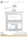
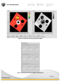
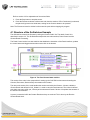
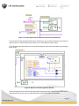
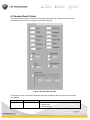
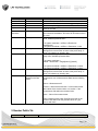
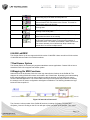
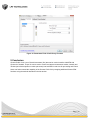
Title:
Revision:
Interfacing Gocator 4.x firmware to LabVIEW
1.1
Table of Contents
1 Overview ................................................................................................................................................................. 2
2 Installing the LabVIEW VIs ..................................................................................................................................... 3
2.1 GoSdk.dll and kApi.dll ...................................................................................................................................... 3
3 Setting up the Gocator to Communicate with LabVIEW ......................................................................................... 3
4 Go2Labview Example ............................................................................................................................................. 4
4.1 Structure of the Go2Labview Example ............................................................................................................. 7
4.2 Gocator Result Cluster ..................................................................................................................................... 9
5 Gocator Public VIs ................................................................................................................................................ 10
6 64-Bit LabVIEW ..................................................................................................................................................... 11
7 Dual-Sensor System ............................................................................................................................................. 11
8 Wrapping Go SDK Functions ................................................................................................................................ 11
9 Conclusion ............................................................................................................................................................ 14
Page | 1
1 Overview
LabVIEW is a comprehensive software package for controlling measurement and control systems. LMI
provides a set of Virtual Instruments (VIs) that can be used to interface LabVIEW with Gocator 2x00
sensors. These VIs can be used to control and stream measurement results, intensity and 3D data (as
individual profiles or whole part scans) into LabVIEW in real-time for processing and control.
This document assumes that LabVIEW is already installed. Users are assumed to be already familiar with
LabVIEW and the Gocator must already be setup to generate profile or whole part data.
Gocator Firmware Release 4.0.0 or later and LabVIEW Version 2010 (32-bit) or later are required.
Page | 2
2 Installing the LabVIEW VIs
The LabView VIs are included in the Gocator Integration Tool package (e.g. 144054.x.x.x_SOFTWARE_Go2_Integration_Tools.zip), under the directory Labview. The VIs are structured
into four directories
Directory
\Labview
\Labview\Examples
\Labview\Private
\Labview\Public
Contents
Labview library project files
Example code that illustrate how to use the public VIs to control the Gocators.
Private files, wrapper VIs of Gocator SDK functions.
Gocator Public VIs. Users use these VIs to control and acquire data from the
Gocator
To open the project, click Go2Labview.lvlb. LabVIEW may prompt you for missing GoSdk.dll the first time
you open the project. When prompted, choose the GoSdk.dll in the \Labview\Private folder and continue.
You should see the following screen. To get the file paths to show up, click Project->Show Item Path.
The 32-bit version of the GoSdk.dll is included in the\Labview\Private area.
2.1 GoSdk.dll and kApi.dll
The VIs in the private folders are building blocks of the Gocator LabVIEW interface. These VIs call
functions exposed in the Gocator SDK DLL (GoSdk.dll). By default, the GoSdk.dll is located in the
\Labview\Private folder.
Each tools package contains the GoSdk.dll that matches with the tool package version. Put the matching
GoSdk.dll and kApi.dll in the Private folder to use the same LabVIEW project for a different Gocator
firmware version.
3 Setting up the Gocator to Communicate with LabVIEW
To communicate with LabVIEW, the Gocator needs to send Profile or Whole Part output over Ethernet
using the Gocator Protocol. The Gocator LabVIEW VIs can receive profile, profile intensity, part, part
intensity and measurement data.
Page | 3
Figure 1. Enabling Output over Ethernet in the Output Page (Surface scan mode shown)
4 Go2Labview Example
Go2Labview is an example of how the Gocator Public VIs can be used. It is also a tool that can be used
to verify the Gocator and the environment is setup correctly. To run the Go2Labview example, expand the
Examples node in the project file, and then double click on Go2Labview_Main.vi.
With the LabVIEW example running, the panel controls the Gocator and displays data generated by the
Gocator in real-time.
Figure 2. Gocator LabVIEW Main Panel
To confirm the GoSdk.dll is installed properly:
1. Run the Go2Labview_Main
2. Check the reported GoSdk.dll version is correct
Page | 4
To connect to the Gocator and acquire data:
1. Press Connect.
Note: IP address is no longer needed as the GoSystem_Connect call will connect to all available sensors on the network.
2. Press Start. The laser line of the sensor should turn on (if the Gocator is in time triggered mode)
and data should start appearing in the displays. If the Gocator is configured to be encoder
triggered, move the encoder in order to trigger data capture.
Figure 3. Go2Labview Running in Profile Mode
Page | 5
Figure 4. Go2Labview Running in Whole Part Mode
Figure 5. Go2LabView displaying Measurement Results
Page | 6
Refer to section 4.2 for explanations of the various fields.
3. Press the Stop button to stop the sensor.
4. Press the Disconnect button to disconnect and close the session. If Run Continuously is selected,
the panel will go back to its initial state, waiting for the Connect button to be pressed.
Note: The Disconnect must be clicked to disconnect the ports before stopping the program.
4.1 Structure of the Go2Labview Example
The Go2Labview controls the Gocator by calling the Gocator Public VIs. The detail of each VI is
described in section 4.2. The Go2Labview example has two main sections; Panel Control and the
Gocator Result Processing.
The Panel Control section is a state machine that handles the interaction of the Panel interface, updates
the control states and triggers actions when users click on the buttons.
Figure 6: The Panel Control state machine
This section of the code is also responsible for setting up the Go2 SDK environment and sending the
Connect, Disconnect, Start and Stop commands to the Gocator.
The other main section of the code handles the results received by the Gocator. A cluster, called the
Gocator Result and defined in Go2_Global.vi, is used to carry the results around. The cluster is defined
such that it can carry profile, par, intensity and measurement results. Section 4.2 explains the structure of
the Gocator Result cluster.
A queue is created to buffer the Gocator Results as they are received. This is done by the Receive
Gocator Result block.
Page | 7
Figure 7. Gocator Result Queue and Block for Receiving the Results
The case structure that encloses the Receive VI queues up a copy of Gocator Result for every frame of
data it receives. A Gocator Result could contain one or more output from the Gocator.
The Process Gocator Result takes the Gocator Result data out of the queue periodically and processes
these results.
Figure 8. Block for Processing Gocator Results
Finally, the last part of the code frees the queue when the program exits. To avoid race conditions, the
code that frees the queue only runs when the Receive and Process loops are terminated.
Page | 8
4.2 Gocator Result Cluster
The Gocator Result cluster is the data structure that carries profile, par, intensity and measurement
results between the user block diagrams and Gocator Public VIs.
Figure 9. Gocator Result Cluster
The structure mirrors the Gocator Data Result defined in the Ethernet Protocol section in the Gocator
User Manual.
Field
Source
Type
U32
Definitions
Profile Source of the data.
0 – Main sensor
1 – Buddy sensor
Page | 9
Timestamp
Encoder
Encoder Index
Frame Count
Exposure
U64
I64
I64
U64
U64
X/Y/Z Offset and
Resolution
Double
Profile
1D array of I16
Profile Intensity
1D array of U8
Part
2D array of I16
100 – Combined data
Timestamp of the frame (us)
Encoder value (ticks)
Encoder value when the last index is triggered. (ticks)
Frame count (frames).
Exposure value (us). This value is only available when
profile is received.
Scale and translation factors for converting pixel coordinates
into real-world coordinates. See below for how these values
are used.
Array of z resampled profile data. Each element is a range
value, 0x8000 represents NULL.
Z in system coordinate = zOffset + zResolution *
ranges[index]
X in system coordinate = xOffset + xResolution * index
Array of profile intensity values. Items in the array are
arranged in the same order as items in the profile array. A
value of 0 indicates no intensity data.
2D Array of z resampled profile data. Each element is a
range value, 0x8000 represents NULL.
Z in system coordinate =
zOffset + zResolution * ranges[indexY] [indexX]
Part Intensity
2D array of U8
Measurements
1D array of
Measurement Data
cluster
X in system coordinate = xOffset + xResolution * indexX.
X in system coordinate = yOffset + yResolution * indexY.
Array of profile intensity values. Items in the array are
arranged in the same order as items in the profile array. A
value of 0 indicates no intensity data.
Each Measurement Data carries the result of one
measurement tool. A Measurement Data has the following
fields:
Source – Measurement ID
Decision – Measurement decision. 0 if the measurement
falls outside of the decision limits or is invalid, 1 if the
measurement falls within the decision limits.
Value – Value of the measurement.
Refer to Measurement under Data Result section in the
Gocator User Manual for the possible values of Type,
Source and Value.
5 Gocator Public VIs
VI
Icons
Explanation
Page | 10
Initialize.vi
Initializes the Go2 SDK environment. Users must call this function
before using any of the other Gocator public VIs
Connect.vi
Constructs the global system handle and establishes the control,
data and health TCP connections to the Gocator. This must be
called before starting the Gocator.
Start the Gocator. The Gocator changes from the Ready to the
Running state.
Start.vi
Stop.vi
Stop the Gocator from running. The Gocator changes from the
Running to the Ready state.
Disconect.vi
Disconnect the TCP connections to the Gocator. This can only be
called when the sensor is not running.
Receive
This VI accepts a queue as the input. On every invocation it polls
the Gocator for the latest result. If a new result is available, it
queues the result. If no results are available, it waits until the next
one comes. Internally it is an infinite loop. Wrap a while loop
around this VI to receive multiple results.
6 64-Bit LabVIEW
The Gocator Public VIs do not support the 64-bit version of LabVIEW. Users can still run 32-bit versions
of LabVIEW with the Public VIs on 64-bit machines.
7 Dual-Sensor System
The Gocator Public VIs currently only supports standalone sensor applications. Contact LMI on how to
extend the Public VIs to support dual-sensor system.
8 Wrapping Go SDK Functions
Under the hood of the Gocator Public VIs is the logic that calls the functions in the GoSdk.dll. The
wrappers for calling GoSdk.dll functions are located in the Private folder. By studying and understanding
these example wrappers, users can then extend or modify the program to create their own custom
Gocator LabVIEW application. The Gocator SDK has many more functions beyond what is covered by
the example, such as sensor configuration and alignment calibration. The following illustrates the logic
inside the Connect public VI.
Figure 10. Internals of Connect VI
The Connect.vi calls a number of the GoSdk.dll functions, including GoSystem_Construct and
GoSystem_Connect. Clicking on the Go icon will open up the front panel of the wrapper. Then select
Page | 11
Window->Show Block Diagram to reveal the internals of the wrapper. Below is the block for calling the
GoSystem_Construct function.
Figure 11. GoSystem_Construct wrapper
The Call Library Function Node wraps the function call to the GoSdk.dll. The Go2Labview_ErrorHandler
is a common block that accepts a kStatus error code and logs an error message if the result is not okay.
Figure 12. Call Library Function Node
To set it up a Call Library Function Node for a new GoSdk.dll function:
1. Open/create the Call Library Function node
2. In the Library name or path field, set the path of the GoSdk.dll to “./Private/GoSdk.dll”. The path is
relative to the location of the VI file.
3. Choose the function from the Function name field.
Page | 12
Figure 13. Function field in Call Library Function Node
4. Switch to the Parameters tab and setup the parameters accordingly.
Page | 13
Figure 14. Parameters Field of Call Library Function
9 Conclusion
Gocator Public VIs is a set of Virtual Instruments (VIs) that can be used to interface LabVIEW with
Gocator 4.x firmware. These VIs can be used to control and stream measurement results, intensity and
3D data (as individual profiles or whole part scans) into LabVIEW in real-time for processing and control.
Users can further extend the capability of the Gocator Public VIs by wrapping additional Gocator SDK
functions using the method described in the last section.
Page | 14